EP1565765B1 - Implementierung einer netzwerkinfrastruktur in ein seismisches aufnahmesystem - Google Patents
Implementierung einer netzwerkinfrastruktur in ein seismisches aufnahmesystem Download PDFInfo
- Publication number
- EP1565765B1 EP1565765B1 EP03796041A EP03796041A EP1565765B1 EP 1565765 B1 EP1565765 B1 EP 1565765B1 EP 03796041 A EP03796041 A EP 03796041A EP 03796041 A EP03796041 A EP 03796041A EP 1565765 B1 EP1565765 B1 EP 1565765B1
- Authority
- EP
- European Patent Office
- Prior art keywords
- seismic
- data
- network
- data collection
- data sources
- Prior art date
- Legal status (The legal status is an assumption and is not a legal conclusion. Google has not performed a legal analysis and makes no representation as to the accuracy of the status listed.)
- Expired - Lifetime
Links
Images


Classifications
-
- G—PHYSICS
- G01—MEASURING; TESTING
- G01V—GEOPHYSICS; GRAVITATIONAL MEASUREMENTS; DETECTING MASSES OR OBJECTS; TAGS
- G01V1/00—Seismology; Seismic or acoustic prospecting or detecting
- G01V1/22—Transmitting seismic signals to recording or processing apparatus
-
- H—ELECTRICITY
- H04—ELECTRIC COMMUNICATION TECHNIQUE
- H04J—MULTIPLEX COMMUNICATION
- H04J3/00—Time-division multiplex systems
- H04J3/02—Details
- H04J3/06—Synchronising arrangements
- H04J3/0635—Clock or time synchronisation in a network
- H04J3/0638—Clock or time synchronisation among nodes; Internode synchronisation
- H04J3/0658—Clock or time synchronisation among packet nodes
- H04J3/0661—Clock or time synchronisation among packet nodes using timestamps
- H04J3/0667—Bidirectional timestamps, e.g. NTP or PTP for compensation of clock drift and for compensation of propagation delays
-
- H—ELECTRICITY
- H04—ELECTRIC COMMUNICATION TECHNIQUE
- H04L—TRANSMISSION OF DIGITAL INFORMATION, e.g. TELEGRAPHIC COMMUNICATION
- H04L12/00—Data switching networks
- H04L12/28—Data switching networks characterised by path configuration, e.g. LAN [Local Area Networks] or WAN [Wide Area Networks]
-
- H—ELECTRICITY
- H04—ELECTRIC COMMUNICATION TECHNIQUE
- H04L—TRANSMISSION OF DIGITAL INFORMATION, e.g. TELEGRAPHIC COMMUNICATION
- H04L61/00—Network arrangements, protocols or services for addressing or naming
Definitions
- the present invention pertains to seismic surveys, and, more particularly, implementing a network infrastructure in a seismic acquisition system.
- Seismic acquisition systems typically are used in seismic surveys.
- an array of seismic receivers is deployed in a selected area.
- One, and usually more, seismic sources are also deployed.
- the sources impart acoustic signals into the ground that are reflected and refracted by subterranean formations back to the receivers.
- the receivers then transmit data indicative of selected characteristics of the reflections to a data collection system.
- the data collection system then collects the data, processes and/or pre-processes it, and, typically, transmits to another location for further processing.
- Seismic surveys can be generally categorized as land-based and water-based (or, "marine"), i.e., by whether they are conducted on land or in the water. Each implicates challenges unique from the other. For instance, in a marine survey, the seismic sources are usually towed at or near the surface of the water. The acoustic signals must therefore propagate through the water before they are imparted into the ground, or sea floor. In contrast, sources in a land-based survey can impart the acoustic signals directly into the ground.
- the present invention is directed to resolving, or at least reducing, one or all of the problems mentioned above.
- US Patent No. 6 459 654 discloses a transmission method for connecting together a central control and seismic recording station, local intermediate control and concentration stations, and local seismic data acquisition, processing and transmission units.
- the method use a transmission network that works according to a defined transmission protocol to connect the central station and the intermediate stations.
- US Patent No. 6 337 636 discloses a data acquisition system having a central station connected to a plurality of nodes over a network. Each node is configured to receive signals from one or more sensors. The central station is configured to notify all nodes of an event time at which a data event, such as a seismic shot, occurred.
- a first aspect of the present invention provides a seismic acquisition system, comprising: a plurality of seismic data sources capable of generating data; at least one data collection system utilizing an open network protocol; and at least one line network connecting the data sources to the data collection system and utilizing an open network protocol, the line network including: a plurality of data source nodes at which a portion of the plurality of seismic data sources are respectively attached to the line network; and a router for routing data generated by the seismic data sources to the data collection system through the data source nodes in accordance with the open network protocol; wherein at least two respective network addresses are assigned to each one of the plurality of seismic data sources, the plurality of data source nodes, the router, and the data collection system.
- a second aspect of the present invention provides a method for use in a seismic survey, the method comprising: assigning at least two respective network addresses to each one of a plurality of seismic data sources, a plurality of data source nodes, a plurality of routers, and a data collection system; routing data generated by the data sources through the data source nodes and the routers to the data collection system; correlating the network addresses of the seismic data sources to the physical location of the respective seismic data sources; and correlating the physical locations of the respective seismic data sources to the data generated by the respective seismic data sources.
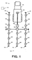
- FIG. 1 depicts the conduct of a seismic survey system 100 in accordance with one aspect of the present invention.
- the seismic survey system 100 is a land-based survey system.
- the seismic survey system 100 accordingly, includes a recording truck 105 connected to a seismic array 110, which is a recording array in the illustrated embodiment.
- the recording array 110 includes a plurality of seismic data sources 120, such as, for example, seismic sources (e.g ., air guns, vibrators, explosive charges), positioning sensors ( G lobal P ositioning S ystem (“GPS”) sensors), seismic receivers ( e.g ., hydrophones, geophones), etc., on a plurality of lines 125. More typically, however, seismic sources, e.g ., the seismic source 115, are not a part of the recording array 110.
- the recording array 110 also includes a plurality of nodes 130 and at least one router 135, whose function will be discussed further below.
- the seismic survey system 100 includes at least one data collection system 140. Note that some alternative embodiments may employ multiple data collection systems 140.
- the recording truck 105 is equipped with a rack-mounted computing apparatus 200, illustrated in FIG. 2A and FIG. 2B, with which at least a portion of data collection system 140 is implemented.
- the computing apparatus 200 includes a processor 205 communicating with some storage 210 over a bus system 215.
- the storage 210 may include a hard disk and/or random access memory ("RAM") and/or removable storage such as a floppy magnetic disk 217 and an optical disk 220.
- the storage 210 is encoded with a data structure 225 storing the data set acquired as discussed above, an operating system 230, user interface software 235, and an application 265.
- the user interface software 235 in conjunction with a display 240, implements a user interface 245.
- the user interface 245 may include peripheral I/O devices such as a key pad or keyboard 250, a mouse 255, or a joystick 260.
- the processor 205 runs under the control of the operating system 230, which may be practically any operating system known to the art.
- the application 265 is invoked by the operating system 230 upon power up, reset, or both, depending on the implementation of the operating system 230, to administer an open network protocol on the recording array 110.
- the administration of this open network protocol imposes a network infrastructure on the seismic acquisition system 100 with which the seismic survey is being conducted.
- a network in a general sense, is a plurality of functionally interconnected computing systems. Note that a computing system may be as simple as a single computing device (e.g. , a controller or processor) or as complex as many individual computers.
- a network protocol (or, more simply, a "protocol") is an agreed upon format for transmitting information between computing devices.
- a protocol typically specifies transmission characteristics such as error checking, data compression, end of message indicators, and return receipts.
- IP Internet Protocol
- "Open” standards are simply standards promulgated by industry groups that are available to the public.
- the IP protocol suite in particular, specifies a format for "packets," or datagrams, that may be addressed to a recipient and then dropped into the network for delivery.
- a single IP-based network i.e., the recording array 110, data collection system 140
- the recording array 110, data collection system 140 is deployed between the different data sources 120 and data collection system(s) 140, allowing communication between data sources 120 and data collection system(s) 140 over any protocol supported on top of IP, which includes most modem, open protocols.
- the node-to-node nature of such a spread network allows communication between the plurality of data sources 120 and, separately, between the plurality of data collection system(s) 140, thereby opening a broad range of possible applications.
- IP protocol suite are particularly useful as applied to the seismic acquisition scenario.
- the generic and wide-spread nature of IP simplifies adapting new services and applications to the seismic acquisition system.
- the protocols comprising the IP protocol suite support dynamically update routing information, which is important in supporting fault tolerance and high availability.
- FIG. 3 illustrates a single line network 300, the elemental building block of the recording array 110 in FIG. 1, connected to the data collection system 140.
- the line network 300 comprises a single router 135 connected between the data collection system 140 and a plurality of nodes 130.
- the nodes 130 are connected to the line 125.
- Each node 130 is, in turn, connected to a string 305 of data sources 120.
- the data sources 120 may be any mix and match of the typical types of equipment used in seismic surveys, e.g ., sources, position sensors, seismic sensors, etc.
- Each of the data collection system 140, the router 135, the nodes 130, and the data sources 120 is assigned two or more, network addresses in accordance with the network protocol administered by the data collection system 140.
- the data source nodes 130 themselves are connected by means of a medium-bandwidth, IP-based network.
- the data source nodes 130 will typically be intelligent units, capable of both initiating and participating in communications sessions with other data source nodes 130 and with the data collection system(s) 140.
- the data source nodes 130 are connected in-line, each data source node 130 connected to at most two neighbouring data source nodes 130 in the illustrated embodiment.
- a number of data source nodes 130 will typically be connected together, forming a string of data source nodes 130, as will be discussed further below. Terminating such a string will be a network router 135.
- the router 135 is a computing device that connects multiple, relatively small networks-such as the line network 300-together. Multiple line networks 300, other routers 135, or data collection systems 140 may be connected to a single router 135.
- the seismic data sources 120 package data into packets (not shown), each of which contains not only data, but a variety of other information. Some of this information is in what is known as the "header" of the packet.
- the header typically contains the network address of the destination for the packet, e.g ., the data collection system(s) 140.
- the router 135 uses this information in the headers of the packets from the seismic data sources 120 and a lookup table (not shown) stored on router 135 to determine the packet's destination. The router 135 then communicates with other routers 135 to determine the best path to that destination through the larger network as a whole.
- the routers 135 communicate among each other using a second open protocol called Open Shortest Pass First ("OSPF"), although alternatives might include Internet Control Message Protocol (“ICMP”), which is a well known extension to the IP protocol suite. Still other open protocols may be used in alternative embodiments.
- OSPF Open Shortest Pass First
- ICMP Internet Control Message Protocol
- the router 135 behaves in the illustrated embodiment as a standard IP network router, routing traffic to and from the data source nodes 120 on the line networks 300 connected to the router 135, as well as traffic to and from the other routers 135 connected to it.
- the connections among the seismic data sensors 120, seismic source nodes 130, the router 135, and the data collection system 140 are all designed to accommodate the amount of network traffic expected to be travelling thereon.
- the line 125 implements, in the illustrated embodiment, a medium-bandwidth data path.
- the connection 310 is a high-bandwidth data path, sometimes referred to in networking parlance as the "backbone.”
- the connection 310 and the line 125 are both electrical, and may be implemented using any suitable electrical technology known to the art. For instance, twisted wire pairs and shielded coaxial cables might be employed in various embodiments. However, this is not required for the practice of the invention.
- the connection 310 and line 125 may alternatively be optical fibres, for instance, or a wireless system.
- the precise parameters regarding the bandwidth of the line 125 and connection 310 will be implementation specific, depending on the number of components (e.g ., seismic data sources 120, data source nodes 130, routers 135, and data collection systems 140), the particular protocol implemented, and the structure of the recording array 110. However, those in the art having the benefit of this disclosure will be able to readily determine these parameters based on standard networking principles and the specifications of the applicable protocols. Furthermore, whether the line 125 or the connection 310 is "high" bandwidth or "medium” bandwidth is not material to the practice of the invention so long as they have the capacity to handle the traffic thereon for the given implementation.
- FIG. 3 illustrates one particular implementation 400 of the recording array 110 in FIG. 1 in which multiple line networks, such as the line network 300 in FIG. 3, are employed to facilitate fault tolerance and spread coverage.
- the degree of fault tolerance and/or spread coverage will be highly implementation specific, depending on the number and arrangement of the line networks 300 therein. Note, however, that various alternative embodiments may employ the invention without necessarily using this "modular" approach.
- the survey apparatus 400 includes multiple data collection units 140 (i.e., DC 0 -DC 3 ), multiple routers 135 ( i.e, R 0 -R 11 ), multiple data source nodes 130 ( i.e ., N 0 -N 15 ), and multiple seismic data sources 120 ( i.e. , S 0 -S 31 ).
- multiple data collection units 140 i.e., DC 0 -DC 3
- multiple routers 135 i.e, R 0 -R 11
- multiple data source nodes 130 i.e ., N 0 -N 15
- multiple seismic data sources 120 i.e. , S 0 -S 31 .
- each router 135 is connected to a data collection system 140 by a backbone 310.
- a break in more than one line or backbone will be survivable as long as more than one backbone and line are available, and they do not affect the same line; not all backbones are broken at the same link 'latilude'; and not all lines are broken. For instance:
- Additional data collection systems 140 can be added to the spread network at any router 135. There may be more than one data collection system 140 connected, and the data collection systems 140 (e.g ., DC 2 , DC 3 ) may be connected at separate routers 135.
- the data collection systems 140 e.g ., DC 1 , DC 2 , DC 3
- the physical area that may be covered by a spread network e.g ., the spread network 400
- the routers 135 may be connected to more than one line network (e.g., R 1 , R 4 , R 7 , R 10 ), thus it will be possible to extend the spread network beyond the limitations of one line network by adding a multiple line networks in the in-line direction. To utilize such a topology one might either add multiple high bandwidth network links to one data collection system 140 as in FIG.1, or add multiple, parallel, data collection systems 140 that collect data from separate parts of the spread network as in FIG. 4.
- line network e.g., R 1 , R 4 , R 7 , R 10
- Another advantage of the spread network of the present invention is that dynamic routing and load balancing techniques can be used to determine which data collection system 140 a given seismic data source 120 should communicate with.
- different channels, routers 135, or data collection systems 140 might receive different levels of traffic. At different times, some routers 135 or data collection systems 140 may be busy while others may be idle. Some might even be borderline overwhelmed by the level of traffic.
- the traffic load on various components such as routers 135 and data collection systems 140 might also vary over time from very busy to very idle. For instance, traffic levels may change over time as new seismic data sources 120 are added, old ones removed, or network failures impact the performance of the spread network.
- Dynamic routing and load balancing techniques have been developed for computing networks to accommodate these types of concerns. These techniques monitor network traffic patterns and adjust network operation to ameliorate the burdens on individual components. These techniques can be applied to the spread network of the present invention to help order traffic therein, adapt to unforeseen exigencies such as equipment failures. Dynamic routing and auto configuration of the network will also facilitate varying the layout and topology of the spread network. This will be particularly useful in "rolling" the spread during seismic operations.
- the open standard-based IP network of the illustrated embodiment is extended with three features adapted to the seismic acquisition environment.
- One is a synchronization service allowing different data source nodes 130 on the spread network (e.g ., 100 or 400) to have real-time clocks that are closely synchronized.
- Seismic surveying in general, employ tighter synchronization than do the computing networks for which the open-protocols have been developed. Hence, the use of the synchronization service.
- the second is a location mapping service enabling the spread network to easily convert a network address to a logical location and vice versa. Seismic surveying also "peg maps" the logical location of the seismic data sources 120 to their location in the network.
- the spread network will support auto-configuration of the network infrastructure itself, e.g. not only will it be possible to dynamically add and remove clients (end-points) from the active network, but also routers. This is useful not only when performing maintenance and repair of malfunctioning components, but also when 'rolling' the seismic spread during normal seismic surveying operations.
- FIG. 5A illustrates timing domains employed in one particular implementation of the recording array 110 in FIG. 1.
- This particular embodiment employs the Network Time Protocol ("NTP") of the Internet Protocol (“IP”) suite of protocols.
- NTP assures accurate synchronization to the millisecond of computer clock times in a network of computers.
- NTP synchronizes client workstation clocks to the U.S. Naval Observatory Master Clocks in Washington, D.C. and Colorado Springs, Colorado.
- NTP sends periodic time requests to servers, obtaining server time stamps and using them to adjust the client's clock.
- the present invention employs NTP in the same fashion.
- the IP protocol NTP is extended with propagation delay measurement to provide sub microsecond accuracy.
- One data collection system 140 is assigned to be the active synchronization master at any one time.
- the active synchronization master is referred to as "Stratum 1" in NTP parlance.
- Synch masters will have access to an external accurate time source (e.g ., a G lobal P ositioning System, or "GPS,” receiver) referred to as "Stratum 0."
- G lobal P ositioning System or "GPS”
- Alternate synch masters can be defined, and they can use the mechanism for time distribution described below to verify the integrity of their respective time sources.
- the underlying network implementation supplies accurate time distribution and clock synchronization features.
- These primitives are used to recursively distribute the real-time as supplied by an "active synchronization master.”
- the primitives transmitted iteratively from the active synchronization master (stratum 1) to the router on the backbone connected to the master.
- This router will then be a backbone network synch master (stratum 2) and will synchronize all routers on the backbone (stratum 3).
- each router will synchronize all line nodes connected to it (stratum 3 or 4). Only the backbone to which the synch master of the moment is connected will be synchronized directly from the active synchronization master.
- Other backbone networks will have their own network synch masters.
- Data collection systems connected to the spread network can be configured to be synchronization clients, e.g ., they can be accurately synchronized with the line nodes, and with other data collection systems without having their own time reference systems.
- the spread network 500 comprises multiple data collections systems DC, routers R, data source nodes N, and seismic data sources S as discussed above.
- the spread network 500 also includes a GPS receiver 502 that provides a clock CLK for the spread network 500.
- the spread network 500 comprises a plurality of synchronization strata 504 defined as described above in accordance with the NTP IP protocol.
- the strata 504 are designated STRATUM 0 - STRATUM 5 .
- the GPS receiver 502 is STRATUM 0 .
- the data collection system 506, connected to the GPS receiver 502, is the designated synchronization master and constitutes STRATUM 1 .
- the data collection system 508 and router 510 connected between the data collection system 506 and the rest of the spread network 500, constitutes STRATUM 2 .
- the line network 512 of the routers 514, 516, 518 are connected between STRATUM 2 and the rest of the spread 500. They consequently constitute STRATUM 3 .
- the line networks 520, 522, 524 of the routers 514, 516, 518, respectively, constitute STRATUM 4 .
- the routers 526, 528, 530 are also a part of STRATUM 4 .
- the line networks 532 and 534 of the routers 528, 530, respectively, and the routers 536, 538 constitute STRATUM 5 .
- the synchronization begins as the data collection system 506, acting as the active synchronization master, passing the primitives to STRATUM 2 .
- the data collection system 508 and router 510 are then synchronized to the clock of the data collection system 506.
- the router 510 then assumes the role of "backbone network synch master" for the backbone 540 and the routers 516 and 518 on the backbone 540.
- the router 510 is also the synch master for the router 514 on the line network 512.
- each router R synchronizes the lines nodes, including both data source nodes N and routers R, on the lines to which it is connected.
- the router 510 passes the primitives to each of the routers 514, 516, 518 in STRATUM 3 .
- Each of the routers 514, 516, 518 passes the primitives to the line nodes on the lines connected thereto.
- the router 514 therefore passes the primitives to the nodes N and routers R on the line network 520, the router 516 does the same on the line network 522, and the router 518 for the line network 524.
- the routers 526, 528, 530 in STRATUM 4 are synched to the routers 514, 516, 518, respectively, in STRATUM 3 .
- the routers 528, 530 then pass the primitives to the routers 536, 538, respectively, in STRATUM 5 . If additional line networks and/or routers and/or data collection systems are added, they can be synchronized to the rest of the spread network 500 in the same iterative fashion across additional strata defined in accordance with the NTP protocol.
- n hops is the number of discrete network link hops from stratum 0.
- a "network link hop” occurs with the regeneration of network time stamps using local real-time clocks.
- the hierarchical scheme imposed by the NTP protocol keeps n hops small relative to the total size of the spread network 500. Note that alternate routing for synchronization is possible using exactly the same fail over and rerouting protocols as for data traffic. That is, in FIG.
- a node N (e.g ., the node 542) will by default be synchronized by a router R (e.g ., the router 514). But, another router R (e.g., the router 510) is also available and able to supply synchronization to the node N, albeit in a higher stratum.
- the ability to supply synchronization along multiple paths also allows time and synchronization verification in the spread network 500. This may be done, e.g ., by comparing multiple synchronization sources against each other.
- FIG. 5B An alternative synchronization technique is illustrated in FIG. 5B.
- the underlying principle of this spread synchronization technique is "local Real Time Clock" ("RTC'') adjustment using:
- RTC synchronization with (sub) micro second accuracy is desirable for seismic acquisition. This level of accuracy generally cannot be achieved if propagation delays, timestamp generation and RTC sampling are not sufficiently deterministic, as is the case with NTP. Fault tolerance and auto configurability generally cannot be achieved if timestamps are distributed by a single source along fixed routes whose delays are measured during system boot. Similarly, bit synchronous networks, where local transmission clocks are derived from those recovered from incoming signals, couple spread synchronization to the initial spread topology.
- FIG. 5B illustrates the flow of timing information in a fragment 550 of a spread having two backbones 552, 554 connected to the same synchronization master 556.
- the synchronization master 556 may be, for instance, a data collection system with access to a GPS receiver to provide a clock in the manner of the data collection system 506 and GPS receiver 502 in the embodiment of FIG. 5A.
- each of the synchronization master 556, and slaves 558, 560, 562, 564, 566 each have a RTC 568. Note that each of the slaves 562, 564, 566 are slaved to the RTC 568 of their neighbour, i.e. , the slaves 558, 562, and 564, respectively.
- the slaves 562, 564, 566 may be seismic data sources, data source nodes, routers, or data collection systems.
- the slaves 558, 560 are slaved to their neighbours, the slave 558 and the synchronization master 556, respectively.
- the slaves 558, 560 in the illustrated embodiment, are routers.
- This "domino synchronization" scheme illustrated in FIG. 5B only measures propagation delay between immediate neighbours, as the timestamps used by a node to adjust its RTC will be generated by one of its neighbours. Because nodes synchronize themselves using only information from their immediate neighbours, the spread topology can change without seriously disrupting spread synchronization.
- the basic elements of the scheme are thus:
- the order and orientations (e.g ., 180° rotations) of data source nodes N are determined to perform "peg mapping.” That is, this information is determined to generate a mapping between seismic survey topology (e.g ., lines and receiver points) and network topology.
- the peg mapping is performed because the absence of true geographical positioning information for data source nodes N and their seismic data sources S.
- Peg mapping is not typically a part of open networking standards, although it is performed in conventional, proprietary protocols. Therefore an additional protocol-mapping node order, node orientation, and defining topology events-is used in conjunction with the open protocol. Topology events include: link up, link down (or node failure) plus node address change.
- Local location information is collected by the routers R and made available, as a service, to interested applications. Peg mapping techniques used on conventional proprietary networks may be employed for this purpose.
- auto configuration of the network infrastructure simplifies flexible deployment and helps automate reconfiguration, e.g ., for spread roll and line fault recovery.
- the core of the auto configuration scheme employed in this particular embodiment is hierarchical addressing coupled with a hierarchy of configurable configuration servers that use contention to resolve conflicts. Note, however, that alternative addressing and contention approaches may be used in alternative embodiments.
- Network addresses in the illustrated embodiment consist of a network number part and a node part in accordance with the open protocol applied as discussed above.
- Network numbers at a particular level in the hierarchy are generated by combining network and nodes numbers from the next higher level using what is basically a left shift (or promotion) of the node part. This addressing may be performed in conventional fashion.
- the illustrated embodiment couples this hierarchical addressing with a hierarchy of configurable "configuration servers.”
- the configuration servers also operate in a hierarchical fashion. Three levels of configuration servers are defined in the illustrated embodiment:
- the data collection unit DC 1 configures itself and passes configuration information to the backbone servers.
- the backbone servers would be the routers R 0 , R 1 , and R 2 .
- the backbone routers configure themselves and then pass configuration information on to the line network servers.
- the routers R 1 , R 2 , R 4 , R 5 , R 7 , R 8 , R 10 , and R 11 may be line network servers.
- the line network servers then configure themselves. Note that the redundancy of the configuration in FIG. 4 provides an alternative configuration, as well.
- the data collection unit DC 2 may be the unique root server
- the routers R 2 , R 5 , R 8 , and R 11 may be the backbone servers
- the routers R 0 , R 1 , R 3 , R 4 , R 6 , R 7 , R 9 , and R 10 may be the line network servers.
- the unique identifiers can either be box serial numbers or some other unique identifier having the same format but which has been set by software.
- the source of the unique identifier is not material to the practice of the invention so long as each potential server's identifier is unique relative to the others.
- the network addresses do not necessarily have anything to do with the unique identifiers used for resolving contention.
- the ability to set an arbitrary value by software can be used by a data collection system wishing to prevent complete reconfiguration of the spread as new nodes are added.
- a configuration server keeps track of its immediate children. When, and if, a configuration server loses contention, it notifies its immediate children that they must restart before it terminates its services. The restarted children thus obtain new configuration information from the winning server. When a child server is asked to restart, it sends further notification to its children before doing so. In order to facilitate node tracking when contention results in reconfiguration, the location services will be notified, so that address updates can be published to interested applications.
- a respective network address is assigned (at 605) to each one of the seismic data sources, data sources data source nodes, routers, and data collection systems.
- at least two respective network addresses are assigned to each one of the seismic data sources, the data source nodes, the routers, and the data collection system.
- this is performed by the line or backbone server 135 (R 0 , R 1 , or R 20 ), although this is not necessary to the practice of the invention. Should two different pieces of equipment attempt to assign addresses, the conflict is, in the illustrated embodiment, resolved through contention as described above.
- the addresses are assigned (at 605) each time the network infrastructure is configured.
- the addresses may be assigned (at 605) either upon power-up as the recording array is deployed, or upon reset, i.e., when the network infrastructure is automatically reconfigured for, e.g., a link going down or coming up.
- data generated by the data sources is routed (at 610) through the data source nodes and the routers to a data collection system.
- the manner in which the data is packaged by the seismic data sources and routed will be implementation specific, depending on the particular open protocol in use. Again, the illustrated embodiment employs the IP protocol as its open protocol, but others may be used in alternative embodiments. Operation of the network infrastructure is synchronized as was described above using, in the illustrated embodiment, the NTP protocol.
- the collected data is then processed.
- the processing involves first correlating the network addresses of the seismic data sources to the logical location of the respective seismic data sources (at 615). This involves first peg mapping the network addresses of the seismic data sources to their logical location in the recording array, as was discussed above.
- the logical locations of the respective seismic data sources to the data generated by the respective seismic data sources is correlated (at 620).
- the data is transmitted from the seismic data sources to the data collection system in packets.
- Each packet typically includes not only data, but a header that includes information such as the source and destination network addresses of the packet.
- the source network address can be extracted from the header of the packet and, having already been correlated to the logical location (at 615), the logical location can then readily be correlated to the data (at 620).
- FIG. 7A and FIG. 7B illustrate the use of the present invention in a land-based seismic survey.
- FIG. 7A shows the seismic recording array 110, first shown in FIG. 1, connected to the recording truck 105.
- the seismic source 115 is also shown.
- the data collection system 140 is shown centrally located on the recording truck 105. However, as will be appreciated by those skilled in the art, various portions of the data collection system 140 may be distributed, e.g ., across the recording array 110, in alternative embodiments.
- a network address is assigned (at 710, FIG. 7B) in accordance with an open network protocol to each one of a plurality of seismic data sources 120, data source nodes 130, and routers 135 (all shown in FIG. 1 ).
- at least two respective network addresses are assigned to each one of the seismic data sources, the data source nodes, the routers, and the data collection system.
- the seismic source 115 generates a plurality of seismic survey signals 715 (at 718, in FIG. 7B) in accordance with conventional practice.
- the seismic survey signals 715 propagate and are reflected by the subterranean geological formation 725.
- the seismic data sources 120 receive (at 730, FIG. 7B) the reflected signals 735 of the generated signals 715.
- some of the seismic data sources 120 are also receiving positioning signals, e.g ., GPS signals, in accordance with conventional practice.
- the seismic data sources 120 then generate (at 738, in FIG. 7B) data representative of the reflections 735.
- the seismic data sources 120 receiving positioning signals also generate data representative of the received positioning signals.
- the generated data is then routed (at 740, in FIG. 7B) from the seismic data sources 120 through the data source nodes 130 and the routers 135 to the data collection system 140 in accordance with the open network protocol.
- the data collection system 140 collects the data for processing.
- the data collection system 140 may process the data itself, store the data for processing at a later time, or transmit the data to a remote location for processing.
- the data collection system 140 processes the data itself.
- the data collection system 140 correlates the network addresses (at 745, in FIG. 7B) of the seismic data sources 120 to the physical location of the respective seismic data sources 120. This involves first determining the logical location of the network address in the recording array 110 using the peg mapping service as was described above. The actual position of the logical location is then determined. The determination of the actual position may be performed using any technique known to the art suitable to the seismic data sources being implemented and the data they generate.
- the physical locations of the respective seismic data sources 120 are then correlated (at 750, in FIG. 7B) to the data generated by the respective seismic data sources 120.
- the data is then used to develop (at 755, in FIG. 7B) a representation of the subterranean formation 725 from the data.
- the software implemented aspects of the invention are typically encoded on some form of program storage medium or implemented over some type of transmission medium.
- the program storage medium may be magnetic (e.g,, a floppy disk or a hard drive) or optical (e.g., a compact disk read only memory, or "CD ROM"), and may be read only or random access.
- the transmission medium may be twisted wire pairs, coaxial cable, optical fibre, or some other suitable transmission medium known to the art. The invention is not limited by these aspects of any given implementation.
Landscapes
- Engineering & Computer Science (AREA)
- Remote Sensing (AREA)
- Physics & Mathematics (AREA)
- Life Sciences & Earth Sciences (AREA)
- Acoustics & Sound (AREA)
- Environmental & Geological Engineering (AREA)
- Geology (AREA)
- General Life Sciences & Earth Sciences (AREA)
- General Physics & Mathematics (AREA)
- Geophysics (AREA)
- Data Exchanges In Wide-Area Networks (AREA)
- Computer And Data Communications (AREA)
Claims (22)
- Seismisches Aufnahmesystem (100), umfassend:eine Vielzahl von seismischen Datenquellen (120, S), die imstande sind, Daten zu erzeugen;mindestens ein Datensammelsystem (140, 506, 508), das ein offenes Netzwerkprotokoll nutzt; undmindestens ein Leitungsnetzwerk (300, 512, 520, 522, 524, 532, 534), das die Datenquellen mit dem Datensammelsystem verbindet und ein offenes Netzwerkprotokoll nutzt, wobei das Leitungsnetzwerk aufweist:dadurch gekennzeichnet, daß jedem aus der Vielzahl von seismischen Datenquellen (120, S), der Vielzahl von Datenquellenknoten (130, N), dem Router und dem Datensammelsystem (140) mindestens zwei jeweilige Netzwerkadressen zugewiesen werden.eine Vielzahl von Datenquellenknoten (130, N), bei denen dem Leitungsnetzwerk jeweils ein Teil der Vielzahl von seismischen Datenquellen (120, S) zugeteilt werden; undeinen Router (135, 510, 514, 516, 518, 526, 528, 530, 536, 538) zum Weiterleiten von Daten, die von den seismischen Datenquellen (120, S) erzeugt werden, über die Datenquellenknoten (130, N) an das Datensammelsystem (140) entsprechend dem offenen Netzwerkprotokoll;
- Seismisches Aufnahmesystem nach Anspruch 1, wobei der Router (135, 510, 514, 516, 518, 526, 528, 530, 536, 538) Daten zu den seismischen Datenquellen (120, S) weiterleitet.
- Seismisches Aufnahmesystem nach Anspruch 1 oder 2, ferner umfassend: mindestens einen zusätzlichen Router zum Weiterleiten von Daten, die von den seismischen Datenquellen (120, S) erzeugt werden, über die Datenquellenknoten (130, N) an das Datensammelsystem (140) entsprechend dem offenen Netzwerkprotokoll.
- Seismisches Aufnahmesystem nach Anspruch 1, 2 oder 3, wobei die seismischen Datenquellen (120, S) mindestens eines von seismischen Quellen (115), seismischen Empfängern und Positionierungsinstrumenten aufweisen.
- Seismisches Aufnahmesystem nach Anspruch 4, wobei die seismischen Quellen (115) mindestens eines von einer Luftkanone, einem Vibrator und einer Explosionsladung aufweisen.
- Seismisches Aufnahmesystem nach Anspruch 4, wobei die seismischen Empfänger mindestens eines von einem Mikrofon und einem Geofon aufweisen.
- Seismisches Aufnahmesystem nach Anspruch 1 bis 6, wobei das offene Netzwerkprotokoll das Internetprotokoll aufweist.
- Seismisches Aufnahmesystem nach einem der Ansprüche 1 bis 7, ferner umfassend: einen Synchronisationsdienst.
- Seismisches Aufnahmesystem nach Anspruch 8, wobei der Synchronisationsdienst das Netzwerkzeitprotokoll umfaßt.
- Seismisches Aufnahmesystem nach einem der Ansprüche 1 bis 7, wobei das mindestens eine Datensammelsystem (506) ferner mindestens eines von folgendem verwaltet:einen Synchronisationsdienst, der eine Vielzahl von Taktgebern für das Datensammelsystem, den Router, die Datenquellenknoten (130, N) und die seismischen Datenquellen (120, S) synchronisiert;einen Standortzuordnungsdienst zur Herstellung von Zuordnungen zwischen Netzwerkadressen und logischen Standorten des Datensammelsystems, des Routers, des Datenquellenknotens (130, N) und der seismischen Datenquellen (120, S); undeine Eigenkonfigurationsfähigkeit zur automatischen Rekonfiguration des Netzwerks bei Entnahme irgendeines von dem Router, den Datenquellenknoten (130, N) oder den seismischen Datenquellen (120, S) oder bei Hinzufügung eines zusätzlichen seismischen Ausrüstungsstückes.
- Seismisches Aufnahmesystem nach Anspruch 10, wobei der Synchronisationsdienst das Netzwerkzeitprotokoll umfaßt.
- Seismisches Aufnahmesystem nach Anspruch 10 oder 11, wobei der Synchronisationsdienst Änderungen der Topologie toleriert.
- Seismisches Aufnahmesystem nach Anspruch 10, 11 oder 12, wobei der Synchronisationsdienst die Taktgeber hierarchisch synchronisiert.
- Seismisches Aufnahmesystem nach einem der Ansprüche 10 bis 13, wobei der Synchronisationsdienst Unterbrechungen bei der Zuteilung zwischen mindestens einer seismischen Datenquelle und dem Leitungsnetzwerk toleriert.
- Seismisches Aufnahmesystem nach einem der Ansprüche 10 bis 14, wobei der Standortzuordnungsdienst Zuordnungen für folgendes herstellt:eine Reihenfolge für das Datensammelsystem, den Router, die Datenquellenknoten und die seismischen Datenquellen;eine Orientierung für jedes von dem Datensammelsystem, dem Router, den Datenquellenknoten und den seismischen Datenquellen; undeine Vielzahl von Topologieereignissen.
- Seismisches Aufnahmesystem nach Anspruch 15, wobei die Topologieereignisse mindestens eines von einer Verbindung, die nach oben führt, einer Verbindung, die nach unten führt, und einer Knotenadressänderung aufweisen.
- Seismisches Aufnahmesystem nach einem der Ansprüche 10 bis 16, wobei das mindestens eine Datensammeisystem eine Vielzahl von Datensammelsystemen umfaßt und der Synchronisationsdienst, der Standortzuordnungsdienst und die Eigenkonfigurationsfähigkeit von mehr als einem aus der Vielzahl von Datensammelsystemen verwaltet werden.
- Verfahren zur Verwendung bei einer seismischen Vermessung, wobei das Verfahren die folgenden Schritte umfaßt:Zuweisen von mindestens zwei jeweiligen Netzwerkadressen an jedes aus einer Vielzahl von seismischen Datenquellen (120, S), einer Vielzahl von Datenquellenknoten (130, N), einer Vielzahl von Routern (135, 510, 514, 516, 518, 526, 528, 530, 536, 538) und einem Datensammelsystem (140, 506, 508);Weiterleiten von Daten, die von den Datenquellen (120, S) erzeugt werden, über die Datenquellenknoten (130, N) und die Router an das Datensammelsystem (140, 506, 508);Korrelieren der Netzwerkadressen der seismischen Datenquellen (120, S) mit dem physischen Standort der jeweiligen seismischen Datenquellen (120, S); undKorrelieren der physischen Standorte der jeweiligen seismischen Datenquellen (120, S) mit den Daten, die von den jeweiligen seismischen Datenquellen (120, S) erzeugt werden.
- Verfahren nach Anspruch 18, wobei das Zuweisen der mindestens zwei jeweiligen Netzwerkadressen an jede aus der Vielzahl von seismischen Datenquellen (120, S) den folgenden Schritt aufweist: Zuweisen von mindestens zwei jeweiligen Netzwerkadressen an jede aus einer Vielzahl von seismischen Datenquellen, einschließlich mindestens eines von einer seismischen Quelle (115), einem seismischen Empfänger und einem Positionierungsinstrument.
- Verfahren nach Anspruch 18 oder 19, ferner mit mindestens einem der folgenden Schritte:Synchronisieren einer Vielzahl von Taktgebern für das Datensammelsystem (140, 506, 508), den Router, die Datenquellenknoten (130, N) und die seismischen Datenquellen (120, S);Herstellen von Zuordnungen zwischen Netzwerkadressen und logischen Standorten des Datensammelsystems (140, 506, 508), des Routers, der Datenquellenknoten (130, N) und der seismischen Datenquellen (120, S); undautomatische Rekonfiguration des Netzwerks bei Entnahme irgendeines von dem Router, den Datenquellenknoten (130, N) oder den seismischen Datenquellen (120, S) oder bei Hinzufügung eines zusätzlichen seismischen Ausrüstungsstückes.
- Verfahren nach Anspruch 20, wobei das Synchronisieren der Vielzahl von Taktgebern den folgenden Schritt aufweist: hierarchisches Synchronisieren der Taktgeber.
- Verfahren nach Anspruch 20, wobei die Herstellung von Zuordnungen zwischen Netzwerkadressen und logischen Standorten des Datensammelsystems die folgenden Schritte aufweist:Zuordnen einer Reihenfolge für das Datensammelsystem (140, 506, 508), den Router, die Datenquellenknoten (130, N) und die seismischen Datenquellen (120, S);Zuordnen einer Orientierung für jedes von dem Datensammelsystem (140, 506, 508), dem Router, den Datenquellenknoten (130, N) und den seismischen Datenquellen (120, S); undZuordnen einer Vielzahl von Topologieereignissen.
Applications Claiming Priority (3)
| Application Number | Priority Date | Filing Date | Title |
|---|---|---|---|
| GB0227292A GB2395640B (en) | 2002-11-22 | 2002-11-22 | Implementing a network infrastructure in a seismic acquisition system |
| GB0227292 | 2002-11-22 | ||
| PCT/EP2003/050871 WO2004049006A1 (en) | 2002-11-22 | 2003-11-21 | Implementing a network infrastructure in a seismic acquisition system |
Publications (2)
| Publication Number | Publication Date |
|---|---|
| EP1565765A1 EP1565765A1 (de) | 2005-08-24 |
| EP1565765B1 true EP1565765B1 (de) | 2006-10-11 |
Family
ID=9948342
Family Applications (1)
| Application Number | Title | Priority Date | Filing Date |
|---|---|---|---|
| EP03796041A Expired - Lifetime EP1565765B1 (de) | 2002-11-22 | 2003-11-21 | Implementierung einer netzwerkinfrastruktur in ein seismisches aufnahmesystem |
Country Status (7)
| Country | Link |
|---|---|
| US (1) | US7898904B2 (de) |
| EP (1) | EP1565765B1 (de) |
| AU (1) | AU2003298309A1 (de) |
| GB (1) | GB2395640B (de) |
| MX (1) | MXPA05005441A (de) |
| RU (1) | RU2328018C2 (de) |
| WO (1) | WO2004049006A1 (de) |
Families Citing this family (38)
| Publication number | Priority date | Publication date | Assignee | Title |
|---|---|---|---|---|
| US7269095B2 (en) * | 2002-10-04 | 2007-09-11 | Aram Systems, Ltd. | Synchronization of seismic data acquisition systems |
| RU2267122C1 (ru) * | 2004-12-15 | 2005-12-27 | Общество с ограниченной ответственностью "ИНТЕРЮНИС" | Многоканальная акустико-эмиссионная система для диагностики промышленных объектов и устройство регистрации и обработки акустико- эмиссионных сигналов |
| US7447238B2 (en) | 2005-04-26 | 2008-11-04 | Westerngeco L.L.C. | Method for compensating for internal delays within each node and transmission delays between the nodes |
| CN100554998C (zh) * | 2006-05-11 | 2009-10-28 | 侯树麒 | 地震勘探数据采集系统 |
| US8898019B2 (en) * | 2007-09-21 | 2014-11-25 | Geospace Technologies, Lp | Low-power satellite-timed seismic data acquisition system |
| GB0725276D0 (en) | 2007-12-28 | 2008-02-06 | Vibration Technology Ltd | Seismic data recording |
| US8181057B2 (en) * | 2008-02-22 | 2012-05-15 | Schlumberger Technology Corporation | Time synchronization in units at different locations |
| US8014677B2 (en) * | 2008-06-30 | 2011-09-06 | Westerngeco L.L.C. | Optical activation of one or more communication units in a survey system |
| US20120106296A1 (en) * | 2008-11-25 | 2012-05-03 | Sercel | Seismic data acquisition system comprising modules associated with units connected to sensors, the modules being autonomous with respect to power supply, synchronisation and storage |
| US9304220B2 (en) * | 2008-12-23 | 2016-04-05 | Westerngeco L.L.C. | Handling equipment failure in a subterranean survey data acquisition network |
| US8594962B2 (en) * | 2009-05-28 | 2013-11-26 | Westerngeco L.L.C. | Distributing a clock in a subterranean survey data acquisition system |
| US20100313252A1 (en) | 2009-06-08 | 2010-12-09 | Erie Trouw | System, method and apparatus for creating and using a virtual layer within a web browsing environment |
| US8635041B2 (en) | 2009-06-11 | 2014-01-21 | WesternGeo L.L.C. | Synchronizing a seismic data acquisition network |
| GB2474882B (en) * | 2009-10-29 | 2014-04-09 | Tgs Geophysical Company Uk Ltd | Signal processing |
| US8483010B2 (en) * | 2010-01-27 | 2013-07-09 | Westerngeco L.L.C. | Providing communications redundancy using one or more loop connections in a subterranean survey system |
| US8400873B2 (en) * | 2010-02-22 | 2013-03-19 | Westerngeco L.L.C. | Vibroseis seismic acquisition technique |
| US20110305114A1 (en) * | 2010-06-11 | 2011-12-15 | Daniel Golparian | Seismic survey communication systems and methods |
| US20120170407A1 (en) * | 2010-12-30 | 2012-07-05 | Wireless Seismic, Inc. | Systems and methods for improving bandwidth of wireless networks |
| JP5120473B2 (ja) * | 2011-03-15 | 2013-01-16 | オムロン株式会社 | ネットワークシステムの設計支援装置 |
| WO2013015795A1 (en) * | 2011-07-26 | 2013-01-31 | Hewlett-Packard Development Company, L.P. | Data exchange with a mobile docking station |
| WO2013076572A2 (en) * | 2011-11-25 | 2013-05-30 | Geco Technology B.V. | Seismic receivers as seismic sources |
| CN103226208B (zh) * | 2012-01-25 | 2018-02-02 | 英洛瓦(天津)物探装备有限责任公司 | 通过光纤的时钟同步 |
| RU2486548C1 (ru) * | 2012-02-10 | 2013-06-27 | Федеральное Государственное Унитарное Предприятие "Сибирский Научно-Исследовательский Институт Геологии, Геофизики И Минерального Сырья" | Многоканальная телеметрическая система сбора и регистрации сейсмических данных |
| CA2866255C (en) | 2012-03-08 | 2021-07-06 | Shell Internationale Research Maatschappij B.V. | Integrated seismic monitoring system and method |
| FR2990028B1 (fr) * | 2012-04-25 | 2014-05-16 | Kietta | Acquisition de donnees sismiques |
| US10069707B2 (en) * | 2012-05-29 | 2018-09-04 | Openet Telecom Ltd. | System and method for seamless horizontal scaling using logical scalable units |
| US10063443B2 (en) | 2012-05-29 | 2018-08-28 | Openet Telecom Ltd. | System and method for managing VoLTE session continuity information using logical scalable units |
| US10097642B2 (en) | 2012-05-29 | 2018-10-09 | Openet Telecom Ltd. | System and method for using VoLTE session continuity information using logical scalable units |
| US20140056103A1 (en) * | 2012-08-22 | 2014-02-27 | Westerngeco L.L.C. | Seismic survey communication systems and methods |
| US20140086008A1 (en) * | 2012-09-24 | 2014-03-27 | Fairfield Industries Incorporated | Inverse timing method, apparatus, and applications |
| US9007231B2 (en) | 2013-01-17 | 2015-04-14 | Baker Hughes Incorporated | Synchronization of distributed measurements in a borehole |
| US9513388B2 (en) * | 2014-03-12 | 2016-12-06 | Sercel | Method for providing synchronization in a data acquisition system |
| US20160011324A1 (en) * | 2014-07-11 | 2016-01-14 | Sercel | Method For Harvesting Seismic Data And Generating Seismic Output Files |
| CN104199083A (zh) * | 2014-08-29 | 2014-12-10 | 中国石油天然气集团公司 | 一种确定宽线地震观测系统的方法和装置 |
| FR3054890B1 (fr) | 2016-08-02 | 2019-07-05 | Kietta | Controle de la position horizontale d’un cable sismique |
| CN106772568A (zh) * | 2017-01-22 | 2017-05-31 | 中国石油天然气集团公司 | 获取采集节点数据的方法、装置、系统及飞行设备 |
| CN116068620A (zh) * | 2022-12-29 | 2023-05-05 | 中国煤炭地质总局地球物理勘探研究院 | 一种具有实时传输功能的节点地震数据采集系统及其方法 |
| CN117544697A (zh) * | 2023-12-05 | 2024-02-09 | 中电信数智科技有限公司 | 一种地震行业协议适配和调度的大数据接入方法 |
Family Cites Families (23)
| Publication number | Priority date | Publication date | Assignee | Title |
|---|---|---|---|---|
| US3881166A (en) * | 1973-05-07 | 1975-04-29 | Geophysical Systems Corp | Data array network systems |
| CA1170756A (en) * | 1980-11-17 | 1984-07-10 | Donald W. Harvey | Remote seismic data system |
| US4885724A (en) * | 1986-03-04 | 1989-12-05 | Amoco Corporation | Cableless seismic digital field recorder having on-site seismic data processing capabilities |
| ES2121860T3 (es) * | 1991-07-19 | 1998-12-16 | Itron Inc | Red de comunicaciones de area amplia para estaciones generadoras de datos remotos. |
| US5627798A (en) * | 1995-05-05 | 1997-05-06 | I/O Exploration Products (U.S.A.), Inc. | Hierarchical telemetry system for seismic acquisition |
| AU4066197A (en) * | 1996-08-12 | 1998-03-06 | Eivind Fromyr | Reservoir acquisition system with concentrator |
| WO1998018022A1 (en) * | 1996-10-23 | 1998-04-30 | Vibration Technology Limited | Seismic acquisition system using wireless telemetry |
| US6131119A (en) * | 1997-04-01 | 2000-10-10 | Sony Corporation | Automatic configuration system for mapping node addresses within a bus structure to their physical location |
| US6205122B1 (en) * | 1998-07-21 | 2001-03-20 | Mercury Interactive Corporation | Automatic network topology analysis |
| US6041283A (en) | 1998-08-07 | 2000-03-21 | Input/Output, Inc. | Remote control system for seismic acquisition |
| US6337636B1 (en) * | 1998-09-16 | 2002-01-08 | Cirrus Logic, Inc. | System and techniques for seismic data acquisition |
| US7107329B1 (en) * | 1999-05-21 | 2006-09-12 | Lucent Technologies Inc. | In networks of interconnected router nodes for routing data traffic, a method of and system for imperceptibly upgrading router node software and the like without traffic interruption |
| US6430547B1 (en) * | 1999-09-22 | 2002-08-06 | International Business Machines Corporation | Method and system for integrating spatial analysis and data mining analysis to ascertain relationships between collected samples and geology with remotely sensed data |
| FR2799004B1 (fr) * | 1999-09-27 | 2001-10-19 | Inst Francais Du Petrole | Methode et systeme de transmission utilisant un reseau de transmission standard, pour relier entre eux des elements d'un dispositif sismique |
| GB0000919D0 (en) * | 2000-01-14 | 2000-03-08 | Geco As | Seismic data acquisition |
| US7002924B2 (en) * | 2000-02-04 | 2006-02-21 | Matsushita Electric Industrial Co., Ltd. | Zero configuration networking |
| AU2001247576A1 (en) * | 2000-03-17 | 2001-10-03 | Optim, L.L.C. | Optimization apparatus, system, and method of use doing business |
| US7237113B2 (en) * | 2000-12-11 | 2007-06-26 | Intel Corporation | Keyed authentication rollover for routers |
| US7047435B2 (en) * | 2000-12-19 | 2006-05-16 | Siemens Corporate Research, Inc. | System and method for clock-synchronization in distributed systems |
| US6980929B2 (en) * | 2001-04-18 | 2005-12-27 | Baker Hughes Incorporated | Well data collection system and method |
| CA2459897C (en) * | 2001-09-07 | 2013-10-29 | Input/Output, Inc. | Seismic data acquisition apparatus and method |
| US20040252585A1 (en) * | 2001-10-10 | 2004-12-16 | Smith Dexter G. | Digital geophone system |
| WO2004034677A2 (en) * | 2002-10-04 | 2004-04-22 | Input/Output, Inc. | Wireless communication method, system and apparatus |
-
2002
- 2002-11-22 GB GB0227292A patent/GB2395640B/en not_active Expired - Fee Related
-
2003
- 2003-11-21 US US10/532,647 patent/US7898904B2/en not_active Expired - Lifetime
- 2003-11-21 RU RU2005119647/28A patent/RU2328018C2/ru not_active IP Right Cessation
- 2003-11-21 MX MXPA05005441A patent/MXPA05005441A/es active IP Right Grant
- 2003-11-21 WO PCT/EP2003/050871 patent/WO2004049006A1/en not_active Ceased
- 2003-11-21 EP EP03796041A patent/EP1565765B1/de not_active Expired - Lifetime
- 2003-11-21 AU AU2003298309A patent/AU2003298309A1/en not_active Abandoned
Also Published As
| Publication number | Publication date |
|---|---|
| EP1565765A1 (de) | 2005-08-24 |
| US7898904B2 (en) | 2011-03-01 |
| MXPA05005441A (es) | 2005-08-03 |
| AU2003298309A1 (en) | 2004-06-18 |
| GB2395640B (en) | 2006-06-07 |
| GB0227292D0 (en) | 2002-12-31 |
| GB2395640A (en) | 2004-05-26 |
| RU2005119647A (ru) | 2006-01-20 |
| WO2004049006A1 (en) | 2004-06-10 |
| US20060155758A1 (en) | 2006-07-13 |
| RU2328018C2 (ru) | 2008-06-27 |
Similar Documents
| Publication | Publication Date | Title |
|---|---|---|
| EP1565765B1 (de) | Implementierung einer netzwerkinfrastruktur in ein seismisches aufnahmesystem | |
| Teixeira et al. | Dynamics of hot-potato routing in IP networks | |
| US20100318299A1 (en) | Synchronizing a seismic data acquisition network | |
| Lai et al. | Measuring bandwidth | |
| EP3326074B1 (de) | Verfahren, systeme und vorrichtung für geografische positionsbestimmung mit spurrouten | |
| Gurewitz et al. | One-way delay estimation using network-wide measurements | |
| US6665316B1 (en) | Organization of time synchronization in a distributed system | |
| Rabbat et al. | Multiple-source Internet tomography | |
| CN106067854B (zh) | 一种网络质量检测方法及设备 | |
| CN101485175A (zh) | 用于散播网络基础设备的地理定位信息的方法 | |
| EP1953962A1 (de) | Grundursachenkorrelation in verbindungslosen Netzen | |
| KR20020089400A (ko) | 가상 존재점을 이용한 서버 모니터링 | |
| US7542537B2 (en) | Method for temporal synchronisation of at least two measuring computers cooperating over a telecommunication network such as internet, intranet or similar | |
| Gopal et al. | Selfish node detection based on evidence by trust authority and selfish replica allocation in DANET | |
| Wood et al. | Fremont: A System for Discovering Network Characteristics and Problems. | |
| Seth et al. | Energy efficient timing-sync protocol for sensor network | |
| Ghafar et al. | Satellite IoT services using multichord peer to peer networking | |
| Laki et al. | A detailed path-latency model for router geolocation | |
| CN1905505B (zh) | 用于地震应用的无线数据采集网络及其方法 | |
| JP5225473B2 (ja) | 通信装置及び通信システム | |
| Arzani et al. | Closing the network diagnostics gap with vigil | |
| US10171337B2 (en) | Method for managing a network, and node for implementing said method | |
| CN105933153A (zh) | 集群故障监测方法及装置 | |
| US7475160B1 (en) | Method and apparatus for a rumor based protocol for distributed state synchronization between request routing servers | |
| US10287875B2 (en) | Scalable borehole acquisition system |
Legal Events
| Date | Code | Title | Description |
|---|---|---|---|
| PUAI | Public reference made under article 153(3) epc to a published international application that has entered the european phase |
Free format text: ORIGINAL CODE: 0009012 |
|
| 17P | Request for examination filed |
Effective date: 20050620 |
|
| AK | Designated contracting states |
Kind code of ref document: A1 Designated state(s): AT BE BG CH CY CZ DE DK EE ES FI FR GB GR HU IE IT LI LU MC NL PT RO SE SI SK TR |
|
| AX | Request for extension of the european patent |
Extension state: AL LT LV MK |
|
| DAX | Request for extension of the european patent (deleted) | ||
| RBV | Designated contracting states (corrected) |
Designated state(s): FR |
|
| GRAP | Despatch of communication of intention to grant a patent |
Free format text: ORIGINAL CODE: EPIDOSNIGR1 |
|
| REG | Reference to a national code |
Ref country code: DE Ref legal event code: 8566 |
|
| RAP1 | Party data changed (applicant data changed or rights of an application transferred) |
Owner name: WESTERNGECO SEISMIC HOLDINGS LIMITED Owner name: SERVICES PETROLIERS SCHLUMBERGER |
|
| GRAS | Grant fee paid |
Free format text: ORIGINAL CODE: EPIDOSNIGR3 |
|
| GRAA | (expected) grant |
Free format text: ORIGINAL CODE: 0009210 |
|
| RAP1 | Party data changed (applicant data changed or rights of an application transferred) |
Owner name: SERVICES PETROLIERS SCHLUMBERGER |
|
| AK | Designated contracting states |
Kind code of ref document: B1 Designated state(s): FR |
|
| ET | Fr: translation filed | ||
| PLBE | No opposition filed within time limit |
Free format text: ORIGINAL CODE: 0009261 |
|
| STAA | Information on the status of an ep patent application or granted ep patent |
Free format text: STATUS: NO OPPOSITION FILED WITHIN TIME LIMIT |
|
| 26N | No opposition filed |
Effective date: 20070712 |
|
| PGFP | Annual fee paid to national office [announced via postgrant information from national office to epo] |
Ref country code: FR Payment date: 20121130 Year of fee payment: 10 |
|
| REG | Reference to a national code |
Ref country code: FR Ref legal event code: ST Effective date: 20140731 |
|
| PG25 | Lapsed in a contracting state [announced via postgrant information from national office to epo] |
Ref country code: FR Free format text: LAPSE BECAUSE OF NON-PAYMENT OF DUE FEES Effective date: 20131202 |
|
| P01 | Opt-out of the competence of the unified patent court (upc) registered |
Effective date: 20231208 |