EP1565674B1 - Method for reducing the power assistance for a gearshifting unit of a vehicle transmission - Google Patents
Method for reducing the power assistance for a gearshifting unit of a vehicle transmission Download PDFInfo
- Publication number
- EP1565674B1 EP1565674B1 EP03767614A EP03767614A EP1565674B1 EP 1565674 B1 EP1565674 B1 EP 1565674B1 EP 03767614 A EP03767614 A EP 03767614A EP 03767614 A EP03767614 A EP 03767614A EP 1565674 B1 EP1565674 B1 EP 1565674B1
- Authority
- EP
- European Patent Office
- Prior art keywords
- gear
- transmission
- power assistance
- range group
- shifting
- Prior art date
- Legal status (The legal status is an assumption and is not a legal conclusion. Google has not performed a legal analysis and makes no representation as to the accuracy of the status listed.)
- Expired - Fee Related
Links
Images


Classifications
-
- F—MECHANICAL ENGINEERING; LIGHTING; HEATING; WEAPONS; BLASTING
- F16—ENGINEERING ELEMENTS AND UNITS; GENERAL MEASURES FOR PRODUCING AND MAINTAINING EFFECTIVE FUNCTIONING OF MACHINES OR INSTALLATIONS; THERMAL INSULATION IN GENERAL
- F16H—GEARING
- F16H61/00—Control functions within control units of change-speed- or reversing-gearings for conveying rotary motion ; Control of exclusively fluid gearing, friction gearing, gearings with endless flexible members or other particular types of gearing
- F16H61/70—Control functions within control units of change-speed- or reversing-gearings for conveying rotary motion ; Control of exclusively fluid gearing, friction gearing, gearings with endless flexible members or other particular types of gearing specially adapted for change-speed gearing in group arrangement, i.e. with separate change-speed gear trains arranged in series, e.g. range or overdrive-type gearing arrangements
- F16H61/702—Control functions within control units of change-speed- or reversing-gearings for conveying rotary motion ; Control of exclusively fluid gearing, friction gearing, gearings with endless flexible members or other particular types of gearing specially adapted for change-speed gearing in group arrangement, i.e. with separate change-speed gear trains arranged in series, e.g. range or overdrive-type gearing arrangements using electric or electrohydraulic control means
-
- F—MECHANICAL ENGINEERING; LIGHTING; HEATING; WEAPONS; BLASTING
- F16—ENGINEERING ELEMENTS AND UNITS; GENERAL MEASURES FOR PRODUCING AND MAINTAINING EFFECTIVE FUNCTIONING OF MACHINES OR INSTALLATIONS; THERMAL INSULATION IN GENERAL
- F16H—GEARING
- F16H61/00—Control functions within control units of change-speed- or reversing-gearings for conveying rotary motion ; Control of exclusively fluid gearing, friction gearing, gearings with endless flexible members or other particular types of gearing
- F16H61/04—Smoothing ratio shift
- F16H61/08—Timing control
-
- F—MECHANICAL ENGINEERING; LIGHTING; HEATING; WEAPONS; BLASTING
- F16—ENGINEERING ELEMENTS AND UNITS; GENERAL MEASURES FOR PRODUCING AND MAINTAINING EFFECTIVE FUNCTIONING OF MACHINES OR INSTALLATIONS; THERMAL INSULATION IN GENERAL
- F16H—GEARING
- F16H59/00—Control inputs to control units of change-speed-, or reversing-gearings for conveying rotary motion
- F16H59/02—Selector apparatus
- F16H59/0278—Constructional features of the selector lever, e.g. grip parts, mounting or manufacturing
- F16H2059/0286—Constructional features of the selector lever, e.g. grip parts, mounting or manufacturing with range or splitter selector on selector lever
-
- F—MECHANICAL ENGINEERING; LIGHTING; HEATING; WEAPONS; BLASTING
- F16—ENGINEERING ELEMENTS AND UNITS; GENERAL MEASURES FOR PRODUCING AND MAINTAINING EFFECTIVE FUNCTIONING OF MACHINES OR INSTALLATIONS; THERMAL INSULATION IN GENERAL
- F16H—GEARING
- F16H61/00—Control functions within control units of change-speed- or reversing-gearings for conveying rotary motion ; Control of exclusively fluid gearing, friction gearing, gearings with endless flexible members or other particular types of gearing
- F16H61/04—Smoothing ratio shift
- F16H61/08—Timing control
- F16H2061/085—Timing of auxiliary gear shifts
-
- F—MECHANICAL ENGINEERING; LIGHTING; HEATING; WEAPONS; BLASTING
- F16—ENGINEERING ELEMENTS AND UNITS; GENERAL MEASURES FOR PRODUCING AND MAINTAINING EFFECTIVE FUNCTIONING OF MACHINES OR INSTALLATIONS; THERMAL INSULATION IN GENERAL
- F16H—GEARING
- F16H59/00—Control inputs to control units of change-speed-, or reversing-gearings for conveying rotary motion
- F16H59/36—Inputs being a function of speed
- F16H59/38—Inputs being a function of speed of gearing elements
- F16H59/40—Output shaft speed
-
- F—MECHANICAL ENGINEERING; LIGHTING; HEATING; WEAPONS; BLASTING
- F16—ENGINEERING ELEMENTS AND UNITS; GENERAL MEASURES FOR PRODUCING AND MAINTAINING EFFECTIVE FUNCTIONING OF MACHINES OR INSTALLATIONS; THERMAL INSULATION IN GENERAL
- F16H—GEARING
- F16H59/00—Control inputs to control units of change-speed-, or reversing-gearings for conveying rotary motion
- F16H59/68—Inputs being a function of gearing status
- F16H59/72—Inputs being a function of gearing status dependent on oil characteristics, e.g. temperature, viscosity
-
- F—MECHANICAL ENGINEERING; LIGHTING; HEATING; WEAPONS; BLASTING
- F16—ENGINEERING ELEMENTS AND UNITS; GENERAL MEASURES FOR PRODUCING AND MAINTAINING EFFECTIVE FUNCTIONING OF MACHINES OR INSTALLATIONS; THERMAL INSULATION IN GENERAL
- F16H—GEARING
- F16H61/00—Control functions within control units of change-speed- or reversing-gearings for conveying rotary motion ; Control of exclusively fluid gearing, friction gearing, gearings with endless flexible members or other particular types of gearing
- F16H61/26—Generation or transmission of movements for final actuating mechanisms
- F16H61/28—Generation or transmission of movements for final actuating mechanisms with at least one movement of the final actuating mechanism being caused by a non-mechanical force, e.g. power-assisted
- F16H61/2807—Generation or transmission of movements for final actuating mechanisms with at least one movement of the final actuating mechanism being caused by a non-mechanical force, e.g. power-assisted using electric control signals for shift actuators, e.g. electro-hydraulic control therefor
-
- Y—GENERAL TAGGING OF NEW TECHNOLOGICAL DEVELOPMENTS; GENERAL TAGGING OF CROSS-SECTIONAL TECHNOLOGIES SPANNING OVER SEVERAL SECTIONS OF THE IPC; TECHNICAL SUBJECTS COVERED BY FORMER USPC CROSS-REFERENCE ART COLLECTIONS [XRACs] AND DIGESTS
- Y10—TECHNICAL SUBJECTS COVERED BY FORMER USPC
- Y10T—TECHNICAL SUBJECTS COVERED BY FORMER US CLASSIFICATION
- Y10T74/00—Machine element or mechanism
- Y10T74/19—Gearing
- Y10T74/19219—Interchangeably locked
- Y10T74/19251—Control mechanism
-
- Y—GENERAL TAGGING OF NEW TECHNOLOGICAL DEVELOPMENTS; GENERAL TAGGING OF CROSS-SECTIONAL TECHNOLOGIES SPANNING OVER SEVERAL SECTIONS OF THE IPC; TECHNICAL SUBJECTS COVERED BY FORMER USPC CROSS-REFERENCE ART COLLECTIONS [XRACs] AND DIGESTS
- Y10—TECHNICAL SUBJECTS COVERED BY FORMER USPC
- Y10T—TECHNICAL SUBJECTS COVERED BY FORMER US CLASSIFICATION
- Y10T74/00—Machine element or mechanism
- Y10T74/19—Gearing
- Y10T74/19219—Interchangeably locked
- Y10T74/19284—Meshing assisters
-
- Y—GENERAL TAGGING OF NEW TECHNOLOGICAL DEVELOPMENTS; GENERAL TAGGING OF CROSS-SECTIONAL TECHNOLOGIES SPANNING OVER SEVERAL SECTIONS OF THE IPC; TECHNICAL SUBJECTS COVERED BY FORMER USPC CROSS-REFERENCE ART COLLECTIONS [XRACs] AND DIGESTS
- Y10—TECHNICAL SUBJECTS COVERED BY FORMER USPC
- Y10T—TECHNICAL SUBJECTS COVERED BY FORMER US CLASSIFICATION
- Y10T74/00—Machine element or mechanism
- Y10T74/20—Control lever and linkage systems
- Y10T74/20012—Multiple controlled elements
- Y10T74/20018—Transmission control
Definitions
- the invention relates to a method for operating a switching unit according to the preamble of claim 1.
- Transmissions of larger commercial vehicles are divided into a main transmission part, a splitter group transmission and a range group transmission.
- Modern transmissions especially in commercial vehicles, have a switching device supported by a pneumatic system, which carries out pneumatic circuits in the split group transmission and in the range group transmission, while the circuits in the main transmission part are performed manually by the driver and can be assisted in the exercising force by the pneumatic system.
- From the DE 198 39 854 A1 has become known a switching device in which a power assistance device supports the shifting force of the driver. In this case, the supply of the supporting compressed air to be reduced, for example, be allowed only when the vehicle clutch is pressed. For this additional valves are required, which allow a reduction.
- the disclosure of the DE 198 39 854 A1 should be the subject of this description in full content.
- the nether-known prior art is the DE 10029497 to zuappelehenen.
- From the DE 100 29 497 A1 is an electro-pneumatic switching unit for a multi-speed vehicle transmission has become known in which is connected with a variety of controlled valves consisting of several modules transmission and this is simultaneously monitored electronically to avoid malfunction. These are the Valves controlled by a central vehicle management computer.
- the disclosure of the DE 100 29 497 A1 should be the subject of this description in full content. An influence of the supporting power does not take place.
- an electro-pneumatic switching unit in which a shuttle valve is provided for a vehicle transmission, which includes a manually switched by the driver to a shift lever main gear and a valve electro-pneumatically switched splitter units.
- the circuits of the splitter group transmission are manually preselected by the driver by switches on the shift lever.
- a sensor or switch detects a manual actuation of the vehicle clutch by the driver and passes this signal to an electronic control device, which then opens the valves.
- the valves open each time in the presence of a clutch actuation signal and always opens that of the two valves, which was selected at the last actuation of the switch for the splitter group transmission on the shift lever.
- An outlet opening of the shuttle valve is connected via a pneumatic line to a pneumatic power assistance device which assists the vehicle operator in the manual transmission in the main transmission.
- the shuttle valve allows only the air supply from one of the two valves of the splitter group to the pneumatic line and thus to the power assistance device, while the other connecting line is shut off by the shuttle valve. This prevents the connected shift cylinder for the splitter group transmission receives an air supply for its two switching directions.
- the already pressurized power assistance device Now acts like a preloaded spring and accelerates the shift rail and shift sleeve to a high speed, which means that when hitting the sliding sleeve on the synchronization, the synchronization no longer locks, but ratchets to produce loud noises.
- These circuits producing ratcheting noise significantly affect the life of the synchronizers as well as all circuit parts. This can even before the failure of the transmission to complaints about the noise and the function of the switching unit lead and thus justify unscheduled workshop visits.
- the invention has for its object to determine the supply of supporting medium of a switching device and avoid damage without much additional effort.
- a gearbox for a vehicle transmission comprises a main transmission part which is manually shifted by the driver on a gearshift lever, a range-group transmission operated by valves, whose gearshifts are preselectable manually by the driver on the gearshift lever, and a power assistance device for shifting the gear ratios in the main transmission part.
- An electronic control device actuates the valves.
- a method for reducing the power assistance is proposed, in which initially the neutral position in the manual switched main transmission part is detected by suitable means is detected and begins with detection of the neutral position, the circuit in the range group transmission part. Delayed at this beginning of the shift in the range group transmission is then the connection of the power assistance for the main transmission part.
- a suitable means for detecting the neutral position may exemplarily be a device that would otherwise be the range of a signal for a starter lock function that can only operate the starter when the main transmission part is in the neutral position, to avoid accidental jumping forward of the vehicle at engine start , Such a device is present in many vehicles.
- the termination of the circuit in the range group transmission is detected and detected after the start of the circuit and after this detection of the termination of the circuit in the range group transmission, the connection of the power assistance for the main transmission part.
- the detection of the termination of the circuit can be done, for example, by detecting the switching path of the shift rail, the interlock or the shift shaft by suitable means.
- the delayed connection of the power assistance for the main transmission part takes place after the start of the circuit, the delayed connection of the power assistance for the main transmission part only after a predetermined time.
- the complete circuit of the range group transmission always runs in the same time, which means that with the detection of a neutral signal in the main transmission part a delayed connection of the power assistance can be such that it coincides exactly with the end of the circuit in the range group transmission .
- the transmission oil temperature detected and the length of this predetermined time until the delayed connection of the power assistance for the main transmission part is determined in dependence on the detected transmission oil temperature.
- the length of the predetermined time until the delayed connection of the power assistance for the main transmission part is determined in a further embodiment in dependence on a transmission output speed, which is also detected.
- a switching operation in the range group transmission takes an exemplary and tentatively detectable time. This tentatively recorded time is preprogrammed in the control device and used as the expected switching time.
- the power assist device is not biased and the ratchet circuits and damage are avoided.
- the Fig. 1 shows a vehicle 2 with a prime mover 4, a transmission 6 and a clutch 8 arranged therebetween.
- the transmission 6 has a main transmission part 10, a split-group transmission 12 and a range group transmission 14.
- the main transmission part 10 is manually switched by the driver via a shift lever 16.
- the transmission 6 is connected via connecting lines 18 to an electronic control device 20.
- Via a supply line 72 arranged in the housing of the transmission 6 valve block 60 is connected to an air reservoir 34.
- a servo-assisting device 74 mounted on or in the housing is operatively connected to the shift lever or members actuated by the shift lever in the main transmission part 10.
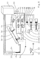
- the Fig. 2 shows an exemplary shift lever 16 in an enlarged view for a circuit diagram 28, which is referred to as "superimposed-H".
- a toggle switch 22 for preselecting the circuit of the splitter group 12 is arranged.
- a further toggle switch 24 is provided, via which the range group transmission 14 is switched.
- Both toggle switches 22, 24 are electrical switches, which are connected via an electrical connection line 26 to the control device 20.
- a circuit with a circuit diagram 28 is in the forward gears each end position of the shift lever sixteenth assigned to two gear ratios, each differing by the ratio jump of the range group transmission 14.
- the change of the range group transmission 14 must select the driver by means of the toggle switch 24 on the shift lever 16. The change is carried out as soon as the neutral position is manually engaged in the main transmission part 10.
- the split group transmission 12 is selected in the positions "L” or “S” with the toggle switch 22 laterally on the shift lever 16 and switched by the actuation of the clutch 8.
- the approval of circuits in the split group transmission 12 is determined in this arrangement by the control device 20 when the switch 64 is closed, wherein the two electropneumatic 3/2-way valves 36 and 38 permanently present air.
- the valves 36 and 38 are connected to the electronic control device 20 and are driven in response to the switch position of the toggle switch 22 on the shift lever 16.
- When depressing the clutch pedal 62 either air in the left or in the right chamber of the shift cylinder 40 of the splitter group transmission 12 is inserted, in which case the respective another chamber via the valves 36 and 38 is vented.
- the driver must preselect the change of the range group transmission 14 by means of the toggle switch 24 on the shift lever 16. The change is then carried out as soon as the neutral position is manually engaged in the main transmission part 10.
- a main shut-off valve 42 mechanically coupled to the shifting movement releases the air from the air reservoir 34 to two electropneumatic 3/2-way valves 44 and 46.
- the valves 44 and 46 are connected to the electronic control device 20 and become dependent on the switch position of the toggle switch 24 is actuated on the shift lever 16.
- a Gassensperrzylinder 54 is provided, preferably in the slow gear ratio of the range group transmission above a certain output speed of the transmission 6 prevents switching from the right shift gate of the circuit diagram 28 in the left shift gate, ie switching from the third or fourth gear stage in the first or second translation stage is prevented. This is to protect the driver from erroneously in the first instead of the fifth gear stage when he has forgotten to select with the toggle switch 24, the fast ratio in the range group transmission. In the fast gear stage of the range group transmission, the same device can be used to prevent circuits from the eighth to the fifth gear stage.
- the output speed of the transmission 6 is detected by a sensor 50 and passed as a signal to the electronic control device 20.
- the control device 20 is at too high output speed from a signal to an electropneumatic 3/2-way valve 52 from which air from the air reservoir 34 via the line 94 to the Gassensperrzylinder 54 can pass, the plunger via a lever 56 in the switching shaft 58th engages and pushes them in the direction of the right shift gate of the circuit diagram 28.
- This arrangement can be overridden by the driver with an increased force and thus allows in extreme situations, the switching of the gear ratios in the left shift gate of the circuit diagram 28th
- a group inhibit suppresses the shifting of the range group transmission 14 to the slow gear ratio and protects both the synchronization of the range group transmission 14 and the synchronizations of the main transmission part 10.
- the vehicle speed is detected via the sensor 50 in accordance with the transmission output rotational speed and as a signal to the control device 20 passed.
- the control device 20 controls the valves 44 and 46 in response to this signal and allows switching to the slow ratio only in the presence of corresponding permissible signals.
- valves 36, 38, 42, 44, 46, 52 and 54 are housed together in the valve block 60 as a common housing, which is mounted directly to a housing in which the switching shaft 58 of the transmission 6 is housed. This results in a compact unit of the valve block 60, which is arranged on the transmission 6 ( Fig. 1 ).
- the short line lengths between the individual valves result in advantageous short reaction times and switching times.
- the electrical connection between valve block 60 and control device 20 can take place via a central electrical connection on the valve block 60.
- the valve block 60 can be connected to an existing transmission without requiring any design changes of the transmission.
- an output line 76 leads to the switching cylinder 40 of the splitter unit 12 and to a first input port 78 of a shuttle valve 80.
- an output line 82 leads to the shift cylinder 40 of the splitter unit 12 and to a second input port 84 of the shuttle valve 80.
- An output port 86 of the shuttle valve 80 is connected to a pneumatic line 88, at which the power assistance device 74 is connected.
- the Fig. 4 shows the timing shift sequence in the main transmission part 10 and the range group transmission 14 for the various elements involved in the circuit.
- the state of driving in fourth gear is first described as an output gear, which then goes into the gear shift from fourth to fifth gear and completes in the state of driving in fifth gear.
- the preselection of the fifth gear takes place.
- the switching process is divided into the circuit in the range group transmission 14 and the circuit in the main transmission part 10. Slightly overlapping sets in the transition of the two circuits, the connection of the power assistance, which uses here approximately with a delay of, for example, up to 0.3 seconds after detecting the neutral position.
- the shift lever 16 During driving in fourth gear, the shift lever 16 is in the position from fourth gear to circuit diagram 28. This also remains so when the toggle 16 of the toggle switch 24 is pressed for the preselection of the switching of the range group transmission 14 in fifth gear. The toggle switch 22 for the preselection of the switching of the splitter group transmission 12 remains unchanged during the entire switching operation.
- the shift lever 16 is then shifted toward the neutral position after the clutch position is changed from “closed” to "open” by operating the clutch pedal 62.
- the movement of the shift lever 16 actuates and opens the main shut-off valve 42, allowing air to the valves 44 ("MV GPL") and 46 ("MV GPS ”) reach.
- the neutral position detection switches from 0 to 1 and the power assistance is turned on delayed.
- the valve 38 (“MV GVS") is opened by the control device 20 and allows the air to reach the servo assistance device 74 via the shuttle valve 80 as long as the clutch pedal 62 is actuated.
Abstract
Description
Die Erfindung betrifft ein Verfahren zum Betreiben einer Schalteinheit nach dem Oberbegriff des Anspruchs 1.The invention relates to a method for operating a switching unit according to the preamble of
Getriebe von größeren Nutzfahrzeugen sind in einen Hauptgetriebeteil, ein Splitgruppengetriebe und ein Bereichsgruppengetriebe aufgeteilt. Moderne Getriebe vor allem in Nutzfahrzeugen weisen dabei eine durch eine Pneumatik unterstützte Schalteinrichtung auf, die pneumatische Schaltungen im Splitgruppengetriebe und im Bereichsgruppengetriebe durchführt, während die Schaltungen im Hauptgetriebeteil manuell vom Fahrzeugführer durchgeführt werden und dabei in der ausübenden Kraft durch die Pneumatik unterstützt werden können.Transmissions of larger commercial vehicles are divided into a main transmission part, a splitter group transmission and a range group transmission. Modern transmissions, especially in commercial vehicles, have a switching device supported by a pneumatic system, which carries out pneumatic circuits in the split group transmission and in the range group transmission, while the circuits in the main transmission part are performed manually by the driver and can be assisted in the exercising force by the pneumatic system.
Aus der
Der Nächtliegende bekanntgewordene Stand der Technik ist der
Aus der
The nether-known prior art is the
From the
Schließlich ist aus der nicht vorveröffentlichten
Bei Schaltgetrieben mit Hauptgetriebe und Bereichsgruppengetriebe ist es möglich, während der ablaufenden Umschaltung im Bereichsgruppengetriebe den Gang im Hauptgetriebeteil anzuwählen und bereits gegen einen das Hauptgetriebe verriegelnden Sperrbolzen eine mehr oder weniger große Handschaltkraft aufzubringen. Ist das Schaltgetriebe mit einer Servounterstützungseinrichtung ausgerüstet, so wird diese, bedingt durch die bereits aufgebrachte Handschaltkraft, ausgelöst, d.h. in der Servounterstützungseinrichtung baut sich schon ein ganz bestimmter Druck auf. Ist nun die Umschaltung im Bereichsgruppengetriebe beendet, so gibt der Sperrbolzen die Schaltung im Hauptgetriebe wieder frei. Die bereits mit Druck beaufschlagte Servounterstützungseinrichtung wirkt nun wie eine vorgespannte Feder und beschleunigt die Schaltschiene und Schaltmuffe auf eine hohe Geschwindigkeit, welche dazu führt, dass beim Auftreffen der Schiebemuffe auf die Synchronisierung die Synchronisierung nicht mehr sperrt, sondern unter Erzeugung lauter Geräusche ratscht. Diese Schaltungen unter Erzeugung von Ratschgeräuschen beeinträchtigen die Lebensdauer der Synchronisierungen sowie aller Schaltungsteile erheblich. Dies kann auch schon vor dem Ausfall des Getriebes zu Beanstandungen bezüglich des Geräusches und der Funktion der Schalteinheit führen und somit außerplanmäßige Werkstattaufenthalte begründen.In manual transmissions with main transmission and range group transmission, it is possible to select the gear in the main transmission part during the ongoing change in the range group transmission and already apply a more or less large manual shift against a locking bolt locking the main gear. If the gearbox is equipped with a servo-assistance device, it will be triggered by the already applied manual shifting force, ie a very specific pressure builds up in the power-assisting device. Now, if the switch in the range group transmission is completed, the locking pin releases the circuit in the main transmission again. The already pressurized power assistance device Now acts like a preloaded spring and accelerates the shift rail and shift sleeve to a high speed, which means that when hitting the sliding sleeve on the synchronization, the synchronization no longer locks, but ratchets to produce loud noises. These circuits producing ratcheting noise significantly affect the life of the synchronizers as well as all circuit parts. This can even before the failure of the transmission to complaints about the noise and the function of the switching unit lead and thus justify unscheduled workshop visits.
Der Erfindung liegt die Aufgabe zugrunde, ohne großen Zusatzaufwand die Zufuhr an unterstützendem Medium einer Schalteinrichtung zu bestimmen und Beschädigungen zu vermeiden.The invention has for its object to determine the supply of supporting medium of a switching device and avoid damage without much additional effort.
Die Aufgabe wird gelöst durch ein Verfahren zur Reduzierung der Servounterstützung an einer Schalteinheit mit den Merkmalen des Anspruchs 1. Ausgestaltungen sind Gegenstand von Unteransprüchen.The object is achieved by a method for reducing the power assistance to a switching unit with the features of
Eine Schalteinheit für ein Fahrzeuggetriebe umfasst ein manuell vom Fahrzeugführer an einem Schalthebel geschaltetes Hauptgetriebeteil, ein über Ventile geschaltetes Bereichsgruppengetriebe, dessen Schaltungen manuell vom Fahrzeugführer an dem Schalthebel vorwählbar sind, und eine Servounterstützungseinrichtung zur Schaltung der Gangstufen im Hauptgetriebeteil. Eine elektronische Steuereinrichtung betätigt die Ventile. Für diese Schalteinheit wird ein Verfahren zur Reduzierung der Servounterstützung vorgeschlagen, bei dem zunächst die Neutralposition in dem manuell geschalteten Hauptgetriebeteil erkannt wird durch geeignete Mittel erkannt wird und mit Erkennen der Neutralposition die Schaltung im Bereichsgruppengetriebeteil beginnt. Verzögert zu diesem Beginn der Schaltung im Bereichsgruppengetriebe erfolgt dann die Zuschaltung der Servounterstützung für den Hauptgetriebeteil. Ein geeignetes Mittel zur Erkennung der Neutralposition kann beispielhaft eine Einrichtung sein, die ansonsten zur Bereichstellung eines Signals für eine Anlasssperrfunktion sein, die den Anlasser nur dann betätigen lässt, wenn das Hauptgetriebeteil in der Neutralposition ist, um ein ungewolltes Vorwärtsspringen des Fahrzeugs beim Motoranlassen zu vermeiden. Eine solche Einrichtung ist in vielen Fahrzeugen vorhanden.
In einer vorteilhaften Ausgestaltung des Verfahrens wird nach dem Beginn der Schaltung auch die Beendigung der Schaltung im Bereichsgruppengetriebe erkannt und festgestellt und nach diesem Erkennen der Beendigung der Schaltung im Bereichsgruppengetriebe erfolgt die Zuschaltung der Servounterstützung für den Hauptgetriebeteil. Das Erkennen der Beendigung der Schaltung kann beispielsweise durch Erfassen des Schaltweges der Schaltschiene, des Interlocks oder der Schaltwelle mit geeigneten Mitteln erfolgen.
In einer weiteren vorteilhaften Ausgestaltung erfolgt nach dem Beginn der Schaltung die verzögerte Zuschaltung der Servounterstützung für den Hauptgetriebeteil erst nach Ablauf einer vorgegebenen Zeit. Bei gleicher Getriebeöltemperatur und gleicher Drehzahl läuft die vollständige Schaltung des Bereichsgruppengetriebes immer in der gleichen Zeit ab, was bedeutet, dass mit dem Erkennen eines Neutralsignals im Hauptgetriebeteil eine verzögerte Zuschaltung der Servounterstützung so erfolgen kann, dass diese genau mit dem Ende der Schaltung im Bereichsgruppengetriebe zusammenfällt. In einer Verfahrensausgestaltung wird die Getriebeöltemperatur erfasst und die Länge dieser vorgegebenen Zeit bis zur verzögerte Zuschaltung der Servounterstützung für den Hauptgetriebeteil wird in Abhängigkeit der erfassten Getriebeöltemperatur bestimmt. Die Länge der vorgegebenen Zeit bis zur verzögerte Zuschaltung der Servounterstützung für den Hauptgetriebeteil wird in einer weiteren Ausgestaltung in Abhängigkeit einer Getriebeabtriebsdrehzahl bestimmt, die ebenfalls erfasst wird.A gearbox for a vehicle transmission comprises a main transmission part which is manually shifted by the driver on a gearshift lever, a range-group transmission operated by valves, whose gearshifts are preselectable manually by the driver on the gearshift lever, and a power assistance device for shifting the gear ratios in the main transmission part. An electronic control device actuates the valves. For this switching unit, a method for reducing the power assistance is proposed, in which initially the neutral position in the manual switched main transmission part is detected by suitable means is detected and begins with detection of the neutral position, the circuit in the range group transmission part. Delayed at this beginning of the shift in the range group transmission is then the connection of the power assistance for the main transmission part. A suitable means for detecting the neutral position may exemplarily be a device that would otherwise be the range of a signal for a starter lock function that can only operate the starter when the main transmission part is in the neutral position, to avoid accidental jumping forward of the vehicle at engine start , Such a device is present in many vehicles.
In an advantageous embodiment of the method, the termination of the circuit in the range group transmission is detected and detected after the start of the circuit and after this detection of the termination of the circuit in the range group transmission, the connection of the power assistance for the main transmission part. The detection of the termination of the circuit can be done, for example, by detecting the switching path of the shift rail, the interlock or the shift shaft by suitable means.
In a further advantageous embodiment takes place after the start of the circuit, the delayed connection of the power assistance for the main transmission part only after a predetermined time. At the same transmission oil temperature and the same speed, the complete circuit of the range group transmission always runs in the same time, which means that with the detection of a neutral signal in the main transmission part a delayed connection of the power assistance can be such that it coincides exactly with the end of the circuit in the range group transmission , In a process design, the transmission oil temperature detected and the length of this predetermined time until the delayed connection of the power assistance for the main transmission part is determined in dependence on the detected transmission oil temperature. The length of the predetermined time until the delayed connection of the power assistance for the main transmission part is determined in a further embodiment in dependence on a transmission output speed, which is also detected.
Bei einer besonders vorteilhaften Verfahrenausführung erfolgt die verzögerte Zuschaltung der Servounterstützung für den Hauptgetriebeteil nach Ablauf einer vorgegebenen Zeit, bis zu deren Ende der Abschluss der Schaltung im Bereichsgruppengetriebeteil üblicherweise erwartet wird. Bei einer getriebeüblichen Öltemperatur von beispielsweise 80 °C dauert ein Schaltvorgang im Bereichsgruppengetriebe eine beispielhafte und versuchsweise erfassbare Zeit. Diese versuchsweise erfasste Zeit wird in der Steuereinrichtung vorprogrammiert und als erwartete Schaltzeit zugrundegelegt.In a particularly advantageous method embodiment, the delayed connection of the power assistance for the main transmission part after a predetermined time until the end of the circuit in the range group transmission part is usually expected to occur. At a transmission usual oil temperature, for example, 80 ° C, a switching operation in the range group transmission takes an exemplary and tentatively detectable time. This tentatively recorded time is preprogrammed in the control device and used as the expected switching time.
Wenn die Servounterstützung im Häuptgetriebeteil erst dann zugeschaltet wird, wenn die Schaltung im Bereichgruppengetriebe beendet ist, das ist die Servounterstützungseinrichtung nicht vorgespannt und die Ratschschaltungen und Beschädigungen werden vermieden.If the power assist in the main section is not engaged until the shift in the range group transmission is completed, the power assist device is not biased and the ratchet circuits and damage are avoided.
Die Erfindung wird anhand einer Zeichnung näher erläutert.The invention will be explained in more detail with reference to a drawing.
- Fig. 1Fig. 1
- eine schematische Darstellung mit Anordnung des Getriebes;a schematic representation with arrangement of the transmission;
- Fig. 2Fig. 2
- einen typischen Schaltgriff mit Schaltbild;a typical handle with circuit diagram;
- Fig. 3Fig. 3
- eine Ausgestaltung der Schalteinheit undan embodiment of the switching unit and
- Fig. 4Fig. 4
- den zeitlichen Schaltungsablauf.the temporal circuit sequence.
Die
Die
Den Wechsel des Bereichsgruppengetriebes 14 muss der Fahrzeugführer mittels des Kippschalters 24 am Schalthebel 16 vorwählen. Der Wechsel wird ausgeführt, sobald im Hauptgetriebeteil 10 manuell die Neutralstellung eingelegt wird.The change of the
Das Splitgruppengetriebe 12 wird in den Positionen "L" oder "S" mit dem Kippschalter 22 seitlich am Schalthebel 16 vorgewählt und durch die Betätigung der Kupplung 8 geschaltet. Dazu zeigt die
Wie bereits ausgeführt muss der Fahrzeugführer den Wechsel des Bereichsgruppengetriebes 14 mittels des Kippschalters 24 am Schalthebel 16 vorwählen. Der Wechsel wird dann ausgeführt, sobald im Hauptgetriebeteil 10 manuell die Neutralstellung eingelegt wird. In der Neutralstellung gibt ein mechanisch an die Schaltbewegung gekoppeltes Hauptabschaltventil 42 die Luft vom Luftvorrat 34 frei zu zwei elektropneumatischen 3/2-Wege-Ventilen 44 und 46. Die Ventile 44 und 46 sind mit der elektronischen Steuereinrichtung 20 verbunden und werden in Abhängigkeit der Schalterstellung des Kippschalters 24 am Schalthebel 16 angesteuert. Bei Erkennen der Neutralstellung durch das Hauptabschaltventil 42 wird über das jeweils angesteuerte Ventil 44 oder 46 entweder Luft in die linke oder in die rechte Kammer des Schaltzylinder 48 des Bereichsgruppengetriebes 14 eingelassen, wobei dann die jeweils andere Kammer über das nicht angesteuerte Ventil 46 bzw. 44 entlüftet wird.As already stated, the driver must preselect the change of the
Um Fehlschaltungen zu vermeiden, müssen in der Schalteinrichtung zusätzliche Absicherungen getroffen werden. Dazu ist ein Gassensperrzylinder 54 vorgesehen, der vorzugsweise in der langsamen Übersetzungsstufe des Bereichsgruppengetriebes oberhalb einer bestimmten Abtriebsdrehzahl des Getriebes 6 das Schalten von der rechten Schaltgasse des Schaltbildes 28 in die linke Schaltgasse verhindert, d. h. das Schalten von der dritten oder vierten Übersetzungsstufe in die erste oder zweite Übersetzungsstufe wird verhindert. Dies soll den Fahrzeugführer davor bewahren, irrtümlich in die erste statt in die fünfte Übersetzungsstufe zu schalten, wenn er vergessen hat, mit dem Kippschalter 24 die schnelle Übersetzung in dem Bereichsgruppengetriebe vorzuwählen. In der schnellen Übersetzungsstufe des Bereichsgruppengetriebes kann die selbe Einrichtung dazu verwendet werden, Schaltungen von der achten in die fünfte Übersetzungsstufe zu verhindern. Die Abtriebsdrehzahl des Getriebes 6 wird von einem Sensor 50 erfasst und als Signal an die elektronische Steuereinrichtung 20 weitergegeben. Die Steuereinrichtung 20 gibt bei zu hoher Abtriebsdrehzahl ein Signal an ein elektropneumatisches 3/2-Wege-Ventil 52 ab, das Luft aus dem Luftvorrat 34 über die Leitung 94 zu dem Gassensperrzylinder 54 gelangen lässt, dessen Stößel über einen Umlenkhebel 56 in die Schaltwelle 58 eingreift und diese in Richtung der rechten Schaltgasse des Schaltbildes 28 drückt. Diese Anordnung ist vom Fahrzeugführer mit einem erhöhten Kraftaufwand überdrückbar und erlaubt somit in Extremsituationen das Schalten der Übersetzungsstufen in der linken Schaltgasse des Schaltbildes 28.In order to avoid switching errors, additional safeguards must be made in the switching device. For this purpose, a Gassensperrzylinder 54 is provided, preferably in the slow gear ratio of the range group transmission above a certain output speed of the
Eine Gruppensperre unterdrückt oberhalb einer vorgegebenen Fahrzeuggeschwindigkeit das Schalten des Bereichsgruppengetriebes 14 in die langsame Übersetzung und schützt sowohl die Synchronisierung des Bereichsgruppengetriebes 14 als auch die Synchronisierungen des Hauptgetriebeteils 10. Die Fahrzeuggeschwindigkeit wird über den Sensor 50 entsprechend der Getriebeabtriebsdrehzahl erfasst und als Signal an die Steuereinrichtung 20 weitergegeben. Die Steuereinrichtung 20 steuert in Abhängigkeit dieses Signals die Ventile 44 bzw. 46 an und lässt ein Schalten in die langsame Übersetzung nur bei Vorliegen entsprechender zulässiger Signale zu.Above a predetermined vehicle speed, a group inhibit suppresses the shifting of the
Die Ventile 36, 38, 42, 44, 46, 52 und 54 sind gemeinsam in dem Ventilblock 60 als einem gemeinsamen Gehäuse untergebracht, der unmittelbar an ein Gehäuse, in welchem die Schaltwelle 58 des Getriebes 6 untergebracht ist, montiert wird. Dadurch ergibt sich eine kompakte Einheit des ventilblocks 60, der am Getriebe 6 angeordnet ist (
Vom Ventil 36 führt eine Ausgangsleitung 76 zum Schaltzylinder 40 des Splitgruppengetriebes 12 und zu einer ersten Eingangsöffnung 78 eines Wechselventils 80. Vom Ventil 38 führt eine Ausgangsleitung 82 zum Schaltzylinder 40 des Splitgruppengetriebes 12 und zu einer zweiten Eingangsöffnung 84 des Wechselventils 80. Erhält das Wechselventil 80 Luft von einer der Eingangsöffnungen 78 oder 84, so verschließt es die jeweils andere Eingangsöffnung 84 oder 78. Dadurch gelangt keine Luft in eine nicht gewollte Arbeitskammer des Schaltzylinders 40. Eine Ausgangsöffnung 86 des Wechselventils 80 ist mit einer Pneumatikleitung 88 verbunden, an der die Servounterstützungseinrichtung 74 angeschlossen ist. Wenn die pneumatischen Leitungen und die Durchlässe durch die Ventile ausreichend dimensioniert sind, genügt die die Pneumatikleitung 88 durchströmende Luft aus, um eine ausreichende Kraft in der Servounterstützungseinrichtung 74 zu erzeugen.From the
Die
Auf der Zeitachse t wird zunächst der Zustand des Fahrens im vierten Gang als Ausgangsgang beschrieben, der dann übergeht in den Schaltvorgang vom vierten in den fünften Gang und abschließt im Zustand des Fahrens im fünften Gang. Während des Fahrens im vierten Gang findet die Vorwahl des fünften Ganges statt. Der Schaltvorgang unterteilt sich in die Schaltung im Bereichsgruppengetriebe 14 und die Schaltung im Hauptgetriebeteil 10. Leicht überschneidend setzt beim Übergang der beiden Schaltungen die Zuschaltung der Servounterstützung ein, die hier in etwa mit einer Verzögerung von beispielsweise bis zu 0.3 Sekunden nach Erkennen der Neutralposition einsetzt.The
On the time axis t, the state of driving in fourth gear is first described as an output gear, which then goes into the gear shift from fourth to fifth gear and completes in the state of driving in fifth gear. While driving in fourth gear, the preselection of the fifth gear takes place. The switching process is divided into the circuit in the
Während des Fahrens im vierten Gang befindet sich der Schalthebel 16 in der Position vom vierten Gang nach Schaltbild 28. Das bleibt auch so, wenn am Schalthebel 16 der Kippschalter 24 für die Vorauswahl der Umschaltung des Bereichsgruppengetriebes 14 in den fünften Gang betätigt wird. Der Kippschalter 22 für die Vorauswahl der Umschaltung des Splitgruppengetriebes 12 bleibt während des gesamten Schaltvorganges unverändert. Der Schalthebel 16 wird dann in Richtung auf die Neutralposition verschoben, nachdem die Kupplungsposition von "Zu" nach "Auf" verändert wurde durch Betätigen des Kupplungspedals 62. Durch die Bewegung von Schalthebel 16 wird das Hauptabschaltventil 42 betätigt und geöffnet und lässt Luft zu den Ventilen 44 ("MV GPL") und 46 ("MV GPS") gelangen. Bei der Vorauswahl der Bereichsgruppenumschaltung wird das Ventil 46 ("MV GPS") geöffnet (0=>1), während gleichzeitig das Ventil 44 ("MV GPL") geschlossen wird (1=>0) und das Ventil 52 ebenfalls geschlossen wird, wodurch der Gassensperrzylinder 56 entsperrt. Nach Erreichen der Neutralposition durch den Schalthebel 16 schaltet die Neutralpositionserkennung von 0 nach 1 und die Servounterstützung wird verzögert eingeschaltet. Nach Ablauf der Verzögerungszeit bzw. nach Erkennen der eingelegten schnellen Schaltstufen im Bereichsgruppengetriebe 14 wird von der Steuereinrichtung 20 das Ventil 38 ("MV GVS") geöffnet und lässt die Luft über das Wechselventil 80 zur Servounterstützungseinrichtung 74 gelangen, solange das Kupplungspedal 62 betätigt ist.During driving in fourth gear, the
Während dieser Zeit vollzieht sich die Schaltung des Bereichsgruppengetriebes 14 vom langsamen in den schnellen Schaltzustand. Anschließend wird bei weiterhin geöffneter Kupplung 8 der Schalthebel 16 in Richtung auf die Schaltposition für den fünften Gang nach Schaltbild 28 verschoben und die Neutralpositionserkennung schaltet von 1 nach 0. Die Schaltposition für den fünften Gang wird erst erreicht, nachdem der Synchronisierungsvorgang im Hauptgetriebeteil 10 abgeschlossen ist. Das Hauptabschaltventil 42 wird wieder geschlossen und sperrt de Luftzufuhr zu den Ventilen 44 und 46 ab. Die Kupplung 62 wird danach wieder geschlossen und das Fahrzeug fährt im fünften Gang.During this time, the shift of the
- 22
- Fahrzeugvehicle
- 44
- Antriebsmaschineprime mover
- 66
- Getriebetransmission
- 88th
- Kupplungclutch
- 1010
- HauptgetriebeteilThe main transmission part
- 1212
- SplitgruppengetriebeSplitter unit
- 1414
- BereichsgruppengetriebeRange gear
- 1616
- Schalthebelgear lever
- 1818
- Verbindungsleitungconnecting line
- 2020
- Steuereinrichtungcontrol device
- 2222
- Kippschaltertoggle switch
- 2424
- Kippschaltertoggle switch
- 2626
- Verbindungsleitungconnecting line
- 2828
- Schaltbildcircuit diagram
- 3434
- Luftvorratair supply
- 3636
- VentilValve
- 3838
- VentilValve
- 4040
- Schaltzylinderswitching cylinder
- 4242
- Hauptabschaltventilmain shut
- 4444
- VentilValve
- 4646
- VentilValve
- 4848
- Schaltzylinderswitching cylinder
- 5050
- Sensorsensor
- 5252
- VentilValve
- 5454
- GassensperrzylinderGate locking cylinder
- 5656
- UmlenkhebelUmlenkhebel
- 5858
- Schaltwelleshift shaft
- 6060
- Ventilblockmanifold
- 6262
- Kupplungspedalclutch pedal
- 6464
- Schalterswitch
- 7272
- Zuleitungsupply
- 7474
- ServounterstützungseinrichtungServo assistance unit
- 7676
- Ausgangsleitungoutput line
- 7878
- Eingangsöffnungentrance opening
- 8080
- Wechselventilshuttle valve
- 8282
- Ausgangsleitungoutput line
- 8484
- Eingangsöffnungentrance opening
- 8686
- Ausgangsöffnungoutput port
- 8888
- Pneumatikleitungpneumatic line
- 9494
- Leitungmanagement
Claims (7)
- Method for reducing the power assistance for a gear-shifting unit for a vehicle transmission (6), which comprises a main transmission component (10) which is shifted manually by the driver of the vehicle at a gear shift lever (16) and a range group transmission (12) which is shifted by means of valves (44, 46) and whose gear-shifting operations can be preselected manually by the driver of the vehicle at the gear shift lever (16), and having a power assistance device (74) for shifting the gear speeds in the main transmission component (10) and having an electronic control device (20) which activates the valves (44, 46), characterized in that the neutral position in the manually shifted main transmission component (10) is detected, and when the neutral position is detected the gear-shifting operation in the range group transmission component (14) starts and the power assistance is activated with a delay.
- Method according to Claim 1, characterized in that the ending of the gear-shifting operation in the range group transmission (14) is detected, and the power assistance is activated after the ending has been detected.
- Method according to Claim 1, characterized in that the delayed activation takes place after a predefined time has expired.
- Method according to Claim 3, characterized in that the transmission oil temperature is sensed, and the predefined time is determined as a function of the sensed transmission oil temperature.
- Method according to Claim 3, characterized in that the transmission output speed is sensed, and the predefined time is determined as a function of the sensed transmission output speed.
- Method according to Claim 3, characterized in that the delayed activation takes place after a predefined time has expired, the termination of the gear-shifting operation in the range group transmission component (14) being usually anticipated by the end of said time.
- Method according to Claim 6, characterized in that the predefined time is determined after the gear-shifting time which is usually required at a predetermined oil temperature.
Applications Claiming Priority (3)
| Application Number | Priority Date | Filing Date | Title |
|---|---|---|---|
| DE10255395 | 2002-11-28 | ||
| DE10255395A DE10255395A1 (en) | 2002-11-28 | 2002-11-28 | switching unit |
| PCT/EP2003/013139 WO2004048817A1 (en) | 2002-11-28 | 2003-11-22 | Method for reducing the power assistance for a gearshifting unit of a vehicle transmission |
Publications (2)
| Publication Number | Publication Date |
|---|---|
| EP1565674A1 EP1565674A1 (en) | 2005-08-24 |
| EP1565674B1 true EP1565674B1 (en) | 2009-04-08 |
Family
ID=32308766
Family Applications (1)
| Application Number | Title | Priority Date | Filing Date |
|---|---|---|---|
| EP03767614A Expired - Fee Related EP1565674B1 (en) | 2002-11-28 | 2003-11-22 | Method for reducing the power assistance for a gearshifting unit of a vehicle transmission |
Country Status (7)
| Country | Link |
|---|---|
| US (1) | US7526975B2 (en) |
| EP (1) | EP1565674B1 (en) |
| JP (1) | JP4574357B2 (en) |
| CN (1) | CN100395472C (en) |
| BR (1) | BR0315199A (en) |
| DE (2) | DE10255395A1 (en) |
| WO (1) | WO2004048817A1 (en) |
Cited By (2)
| Publication number | Priority date | Publication date | Assignee | Title |
|---|---|---|---|---|
| DE102010043685A1 (en) | 2010-11-10 | 2012-05-10 | Zf Friedrichshafen Ag | Group transmissions for motor vehicles |
| WO2013020761A1 (en) | 2011-08-11 | 2013-02-14 | Zf Friedrichshafen Ag | Method for shift control of an automated group gear |
Families Citing this family (7)
| Publication number | Priority date | Publication date | Assignee | Title |
|---|---|---|---|---|
| CN100412417C (en) * | 2006-01-13 | 2008-08-20 | 华南理工大学 | Programmable logic control device for automobile transmission case with manual gearshift |
| DE102006034947A1 (en) * | 2006-07-28 | 2008-01-31 | Zf Friedrichshafen Ag | Switchgear for a group transmission and method for controlling a switching device for a group transmission |
| DE102007032936A1 (en) * | 2007-07-14 | 2009-01-15 | Zf Friedrichshafen Ag | Method and circuitry for assisting a shift in a manual transmission |
| US20130220055A1 (en) * | 2012-02-28 | 2013-08-29 | Nissan North America, Inc. | Multifunctional integrated shifter |
| EP3559508B1 (en) | 2016-12-22 | 2023-07-12 | Eaton Cummins Automated Transmission Technologies, LLC | High efficiency, high output transmission |
| US10584778B2 (en) | 2016-12-22 | 2020-03-10 | Eaton Cummins Automated Transmission Technologies, Llc | High efficiency, high output transmission |
| US11105412B2 (en) * | 2016-12-22 | 2021-08-31 | Eaton Cummins Automated Transmission Technologies Llc | System, method, and apparatus for managing transmission shutdown operations |
Family Cites Families (15)
| Publication number | Priority date | Publication date | Assignee | Title |
|---|---|---|---|---|
| CN1034336A (en) * | 1988-01-23 | 1989-08-02 | 克塞贝尔·奥托吉亚 | Utilize the system that advances starting road vehicle driving engine |
| JP2739121B2 (en) * | 1989-09-05 | 1998-04-08 | トヨタ自動車株式会社 | Transmission control device for automatic transmission |
| US5329826A (en) * | 1992-01-22 | 1994-07-19 | Eaton Corporation | Enhanced automated splitter shifting with dual solenoid valves and auto fuel control |
| DE19754726B4 (en) * | 1997-12-10 | 2005-08-25 | Zf Friedrichshafen Ag | Method for changing the gears of a multi-gear manual gear change gear for commercial vehicles |
| US5931055A (en) * | 1997-12-23 | 1999-08-03 | Meritor Heavy Vehicle Systems, Llc | Electrical transmission range shift system |
| US6109126A (en) * | 1998-05-27 | 2000-08-29 | Transmission Technologies Corporation | Shift control system for an auxiliary section of a compound vehicular transmission |
| DE19839854A1 (en) * | 1998-09-02 | 2000-03-09 | Zahnradfabrik Friedrichshafen | Switching device for motor vehicle gearbox |
| EP1092894B1 (en) * | 1999-10-12 | 2007-01-03 | Eaton Corporation | Control for engaging start ratios in controller-assisted, manually shifted, splitter-type compound transmissions |
| JP4058868B2 (en) * | 1999-11-10 | 2008-03-12 | いすゞ自動車株式会社 | Multistage transmission for vehicles |
| US6319171B1 (en) * | 2000-04-27 | 2001-11-20 | Eaton Corporation | Synchronizing control and method |
| US6361473B1 (en) * | 2000-04-27 | 2002-03-26 | Eaton Corporation | System/method for synchronized shifting of a manually shifted transmission |
| DE10029497A1 (en) * | 2000-06-15 | 2002-01-10 | Zahnradfabrik Friedrichshafen | Electro-pneumatic switching unit |
| JP2002227980A (en) * | 2001-01-30 | 2002-08-14 | Hitachi Ltd | Automatic transmission control device for vehicle and control method |
| DE10217482A1 (en) | 2002-04-19 | 2003-11-06 | Zahnradfabrik Friedrichshafen | Electro-pneumatic switching unit |
| DE10252429A1 (en) * | 2002-11-12 | 2004-05-27 | Zf Friedrichshafen Ag | Electropneumatic switching unit for a vehicle drive especially a truck drive has mechanism to block forbidden gear ratio changes |
-
2002
- 2002-11-28 DE DE10255395A patent/DE10255395A1/en not_active Ceased
-
2003
- 2003-11-22 JP JP2004554428A patent/JP4574357B2/en not_active Expired - Fee Related
- 2003-11-22 US US10/535,830 patent/US7526975B2/en not_active Expired - Fee Related
- 2003-11-22 DE DE50311400T patent/DE50311400D1/en not_active Expired - Lifetime
- 2003-11-22 BR BR0315199-9A patent/BR0315199A/en not_active IP Right Cessation
- 2003-11-22 WO PCT/EP2003/013139 patent/WO2004048817A1/en active Application Filing
- 2003-11-22 EP EP03767614A patent/EP1565674B1/en not_active Expired - Fee Related
- 2003-11-22 CN CNB2003801017565A patent/CN100395472C/en not_active Expired - Fee Related
Cited By (5)
| Publication number | Priority date | Publication date | Assignee | Title |
|---|---|---|---|---|
| DE102010043685A1 (en) | 2010-11-10 | 2012-05-10 | Zf Friedrichshafen Ag | Group transmissions for motor vehicles |
| WO2012062536A1 (en) | 2010-11-10 | 2012-05-18 | Zf Friedrichshafen Ag | Group transmission for motor vehicles |
| WO2013020761A1 (en) | 2011-08-11 | 2013-02-14 | Zf Friedrichshafen Ag | Method for shift control of an automated group gear |
| DE102011080849A1 (en) | 2011-08-11 | 2013-02-14 | Zf Friedrichshafen Ag | Method for switching control of an automated group transmission |
| US8870712B2 (en) | 2011-08-11 | 2014-10-28 | Zf Friedrichshafen Ag | Method for shift control of an automated group gear |
Also Published As
| Publication number | Publication date |
|---|---|
| US7526975B2 (en) | 2009-05-05 |
| WO2004048817A1 (en) | 2004-06-10 |
| BR0315199A (en) | 2005-08-23 |
| JP4574357B2 (en) | 2010-11-04 |
| DE10255395A1 (en) | 2004-06-09 |
| EP1565674A1 (en) | 2005-08-24 |
| CN1705838A (en) | 2005-12-07 |
| DE50311400D1 (en) | 2009-05-20 |
| JP2006508308A (en) | 2006-03-09 |
| US20060053928A1 (en) | 2006-03-16 |
| CN100395472C (en) | 2008-06-18 |
Similar Documents
| Publication | Publication Date | Title |
|---|---|---|
| DE102007006354B4 (en) | Parking lock assembly for an electric transmission range selection system | |
| DE4420930C2 (en) | Device and method for controlling an automatic shifting device of a gear change transmission of a motor vehicle | |
| DE10336520B4 (en) | Hydraulic pressure control device and method for an automatic transmission of a vehicle | |
| DE19907141A1 (en) | Electronically controlled gear changing system for manual transmission of a motor vehicle | |
| EP2013516B1 (en) | Method for operating an automatic gearbox | |
| DE102006014947A1 (en) | Automatic transmission e.g. step automatic transmission, operating method for motor vehicle, involves closing three switching elements of step automatic transmission for moment and/or power transmission into forward gear and reverse gear | |
| EP1497575B1 (en) | Electropneumatic gearshift unit | |
| EP1565674B1 (en) | Method for reducing the power assistance for a gearshifting unit of a vehicle transmission | |
| DE19800880A1 (en) | Gearshift with park setting | |
| DE10106813A1 (en) | Shift control device has guide paths for shifting shift lever between neutral and parking positions, and another guide path for shifting shift lever to advance, neutral or reverse positions | |
| DE19615267C1 (en) | Automated manual gear-shift circuit arrangement for motor vehicle transmission | |
| EP1668275B1 (en) | Gearbox with electro-pneumatic switch unit | |
| EP1654482B1 (en) | Electro-pneumatic switch unit | |
| DE102005057816B4 (en) | Method for actuating switching elements of a dual-clutch transmission | |
| EP1561053B1 (en) | Electro-pneumatic switching unit | |
| DE19815666B4 (en) | Method for operating an actuator for the automated actuation of a friction clutch and an automated manual transmission | |
| EP1558863B1 (en) | Switching unit | |
| DE102008054846A1 (en) | Electro-pneumatic switch unit for vehicle gear box, has area auxiliary transmission pneumatically switched by valves with two transmission ratio levels and manually switched main gear box | |
| DE19858540A1 (en) | Electronic-hydraulic control device for motor vehicle automatic gearbox acts via electrical interaction to drive control unit that drives couplings and brakes via electrically actuated valves | |
| WO1990014534A1 (en) | Electro-pneumatic gear changing system | |
| DE2529722A1 (en) | Gear change control for construction vehicle - with control valves directly linked to reservoir for fast response | |
| DE4015290A1 (en) | Electropneumatic gear change system with special emergency valve - includes standby compressed air supply with multi-position valve and electrical switch closed in its inoperative position | |
| DE10127759B4 (en) | Powertrain system and method for controlling a powertrain system for a motor vehicle | |
| DE10246301A1 (en) | Gearshift control method for controlling gearshift movements in an automatic gearbox and a reducing gear system in a motor vehicle uses two gear speed stages |
Legal Events
| Date | Code | Title | Description |
|---|---|---|---|
| PUAI | Public reference made under article 153(3) epc to a published international application that has entered the european phase |
Free format text: ORIGINAL CODE: 0009012 |
|
| 17P | Request for examination filed |
Effective date: 20050216 |
|
| AK | Designated contracting states |
Kind code of ref document: A1 Designated state(s): AT BE BG CH CY CZ DE DK EE ES FI FR GB GR HU IE IT LI LU MC NL PT RO SE SI SK TR |
|
| RBV | Designated contracting states (corrected) |
Designated state(s): DE |
|
| GRAJ | Information related to disapproval of communication of intention to grant by the applicant or resumption of examination proceedings by the epo deleted |
Free format text: ORIGINAL CODE: EPIDOSDIGR1 |
|
| GRAP | Despatch of communication of intention to grant a patent |
Free format text: ORIGINAL CODE: EPIDOSNIGR1 |
|
| GRAP | Despatch of communication of intention to grant a patent |
Free format text: ORIGINAL CODE: EPIDOSNIGR1 |
|
| GRAJ | Information related to disapproval of communication of intention to grant by the applicant or resumption of examination proceedings by the epo deleted |
Free format text: ORIGINAL CODE: EPIDOSDIGR1 |
|
| GRAP | Despatch of communication of intention to grant a patent |
Free format text: ORIGINAL CODE: EPIDOSNIGR1 |
|
| RIC1 | Information provided on ipc code assigned before grant |
Ipc: F16H 61/02 20060101AFI20080930BHEP Ipc: F16H 63/44 20060101ALI20080930BHEP |
|
| GRAS | Grant fee paid |
Free format text: ORIGINAL CODE: EPIDOSNIGR3 |
|
| GRAA | (expected) grant |
Free format text: ORIGINAL CODE: 0009210 |
|
| STAA | Information on the status of an ep patent application or granted ep patent |
Free format text: STATUS: THE PATENT HAS BEEN GRANTED |
|
| AK | Designated contracting states |
Kind code of ref document: B1 Designated state(s): DE |
|
| REF | Corresponds to: |
Ref document number: 50311400 Country of ref document: DE Date of ref document: 20090520 Kind code of ref document: P |
|
| PLBI | Opposition filed |
Free format text: ORIGINAL CODE: 0009260 |
|
| 26 | Opposition filed |
Opponent name: VOLVO LASTVAGNAR AB Effective date: 20100106 |
|
| PLAB | Opposition data, opponent's data or that of the opponent's representative modified |
Free format text: ORIGINAL CODE: 0009299OPPO |
|
| R26 | Opposition filed (corrected) |
Opponent name: VOLVO LASTVAGNAR AB Effective date: 20100106 |
|
| PLBG | Opposition deemed not to have been filed |
Free format text: ORIGINAL CODE: 0009274 |
|
| 26D | Opposition deemed not to have been filed |
Opponent name: VOLVO LASTVAGNAR AB Effective date: 20110621 |
|
| PGFP | Annual fee paid to national office [announced via postgrant information from national office to epo] |
Ref country code: DE Payment date: 20191112 Year of fee payment: 17 |
|
| REG | Reference to a national code |
Ref country code: DE Ref legal event code: R119 Ref document number: 50311400 Country of ref document: DE |
|
| PG25 | Lapsed in a contracting state [announced via postgrant information from national office to epo] |
Ref country code: DE Free format text: LAPSE BECAUSE OF NON-PAYMENT OF DUE FEES Effective date: 20210601 |