EP1565329B1 - Tyre with extended mobility with substantially low-modulus anchoring zone - Google Patents
Tyre with extended mobility with substantially low-modulus anchoring zone Download PDFInfo
- Publication number
- EP1565329B1 EP1565329B1 EP03758080A EP03758080A EP1565329B1 EP 1565329 B1 EP1565329 B1 EP 1565329B1 EP 03758080 A EP03758080 A EP 03758080A EP 03758080 A EP03758080 A EP 03758080A EP 1565329 B1 EP1565329 B1 EP 1565329B1
- Authority
- EP
- European Patent Office
- Prior art keywords
- zone
- anchoring
- bead
- tyre
- mpa
- Prior art date
- Legal status (The legal status is an assumption and is not a legal conclusion. Google has not performed a legal analysis and makes no representation as to the accuracy of the status listed.)
- Expired - Lifetime
Links
- 238000004873 anchoring Methods 0.000 title claims abstract description 79
- 239000011324 bead Substances 0.000 claims abstract description 118
- 229920001971 elastomer Polymers 0.000 claims abstract description 75
- 239000005060 rubber Substances 0.000 claims abstract description 61
- 230000002787 reinforcement Effects 0.000 claims description 69
- 239000000806 elastomer Substances 0.000 claims description 15
- 230000003068 static effect Effects 0.000 claims description 12
- 229920003051 synthetic elastomer Polymers 0.000 claims description 9
- 229920002857 polybutadiene Polymers 0.000 claims description 7
- 239000005062 Polybutadiene Substances 0.000 claims description 5
- 229920003048 styrene butadiene rubber Polymers 0.000 claims description 5
- 239000000203 mixture Substances 0.000 abstract description 77
- 230000003014 reinforcing effect Effects 0.000 abstract description 25
- 238000012360 testing method Methods 0.000 description 43
- 238000004519 manufacturing process Methods 0.000 description 10
- 238000000034 method Methods 0.000 description 10
- 239000000047 product Substances 0.000 description 8
- 239000011248 coating agent Substances 0.000 description 6
- 238000000576 coating method Methods 0.000 description 6
- 239000002184 metal Substances 0.000 description 5
- 229910052751 metal Inorganic materials 0.000 description 5
- 230000008569 process Effects 0.000 description 5
- 239000011265 semifinished product Substances 0.000 description 5
- 238000004804 winding Methods 0.000 description 5
- 230000007423 decrease Effects 0.000 description 4
- 239000000463 material Substances 0.000 description 4
- NINIDFKCEFEMDL-UHFFFAOYSA-N Sulfur Chemical compound [S] NINIDFKCEFEMDL-UHFFFAOYSA-N 0.000 description 3
- 238000000429 assembly Methods 0.000 description 3
- 230000000712 assembly Effects 0.000 description 3
- 239000006229 carbon black Substances 0.000 description 3
- 239000000470 constituent Substances 0.000 description 3
- 238000007796 conventional method Methods 0.000 description 3
- 238000009472 formulation Methods 0.000 description 3
- 230000000670 limiting effect Effects 0.000 description 3
- 238000012423 maintenance Methods 0.000 description 3
- 238000000518 rheometry Methods 0.000 description 3
- 229910052717 sulfur Inorganic materials 0.000 description 3
- 239000011593 sulfur Substances 0.000 description 3
- 241001644893 Entandrophragma utile Species 0.000 description 2
- 244000043261 Hevea brasiliensis Species 0.000 description 2
- RRHGJUQNOFWUDK-UHFFFAOYSA-N Isoprene Chemical compound CC(=C)C=C RRHGJUQNOFWUDK-UHFFFAOYSA-N 0.000 description 2
- PXHVJJICTQNCMI-UHFFFAOYSA-N Nickel Chemical class [Ni] PXHVJJICTQNCMI-UHFFFAOYSA-N 0.000 description 2
- 230000004308 accommodation Effects 0.000 description 2
- 150000001875 compounds Chemical class 0.000 description 2
- 238000007906 compression Methods 0.000 description 2
- 230000006835 compression Effects 0.000 description 2
- 238000013461 design Methods 0.000 description 2
- 229920003052 natural elastomer Polymers 0.000 description 2
- 229920001194 natural rubber Polymers 0.000 description 2
- 229920001195 polyisoprene Polymers 0.000 description 2
- 238000000926 separation method Methods 0.000 description 2
- 238000004381 surface treatment Methods 0.000 description 2
- 238000012546 transfer Methods 0.000 description 2
- 230000007704 transition Effects 0.000 description 2
- 238000011282 treatment Methods 0.000 description 2
- 229910001369 Brass Inorganic materials 0.000 description 1
- 241000897276 Termes Species 0.000 description 1
- 230000002159 abnormal effect Effects 0.000 description 1
- 230000001133 acceleration Effects 0.000 description 1
- 230000009471 action Effects 0.000 description 1
- 239000000654 additive Substances 0.000 description 1
- 238000004026 adhesive bonding Methods 0.000 description 1
- 238000004458 analytical method Methods 0.000 description 1
- 239000004760 aramid Substances 0.000 description 1
- 229920003235 aromatic polyamide Polymers 0.000 description 1
- 239000010951 brass Substances 0.000 description 1
- 229910017052 cobalt Inorganic materials 0.000 description 1
- 239000010941 cobalt Substances 0.000 description 1
- GUTLYIVDDKVIGB-UHFFFAOYSA-N cobalt atom Chemical class [Co] GUTLYIVDDKVIGB-UHFFFAOYSA-N 0.000 description 1
- 235000009508 confectionery Nutrition 0.000 description 1
- 239000013256 coordination polymer Substances 0.000 description 1
- 230000008878 coupling Effects 0.000 description 1
- 238000010168 coupling process Methods 0.000 description 1
- 238000005859 coupling reaction Methods 0.000 description 1
- 230000000593 degrading effect Effects 0.000 description 1
- 238000011161 development Methods 0.000 description 1
- 230000018109 developmental process Effects 0.000 description 1
- 238000004455 differential thermal analysis Methods 0.000 description 1
- 230000000694 effects Effects 0.000 description 1
- 230000008030 elimination Effects 0.000 description 1
- 238000003379 elimination reaction Methods 0.000 description 1
- 229940082150 encore Drugs 0.000 description 1
- 238000005516 engineering process Methods 0.000 description 1
- 238000002474 experimental method Methods 0.000 description 1
- 230000009477 glass transition Effects 0.000 description 1
- 230000006872 improvement Effects 0.000 description 1
- 230000001939 inductive effect Effects 0.000 description 1
- 230000002401 inhibitory effect Effects 0.000 description 1
- 238000002955 isolation Methods 0.000 description 1
- 230000014759 maintenance of location Effects 0.000 description 1
- 238000005259 measurement Methods 0.000 description 1
- 238000002156 mixing Methods 0.000 description 1
- 230000007935 neutral effect Effects 0.000 description 1
- 229910052759 nickel Chemical class 0.000 description 1
- 238000005457 optimization Methods 0.000 description 1
- 230000002829 reductive effect Effects 0.000 description 1
- 239000012763 reinforcing filler Substances 0.000 description 1
- 238000005096 rolling process Methods 0.000 description 1
- 150000003839 salts Chemical class 0.000 description 1
- 238000007789 sealing Methods 0.000 description 1
- 238000004513 sizing Methods 0.000 description 1
- 239000007787 solid Substances 0.000 description 1
- 230000001629 suppression Effects 0.000 description 1
- 239000004753 textile Substances 0.000 description 1
- 230000009466 transformation Effects 0.000 description 1
- 238000000844 transformation Methods 0.000 description 1
- 238000004073 vulcanization Methods 0.000 description 1
Images


Classifications
-
- B—PERFORMING OPERATIONS; TRANSPORTING
- B60—VEHICLES IN GENERAL
- B60C—VEHICLE TYRES; TYRE INFLATION; TYRE CHANGING; CONNECTING VALVES TO INFLATABLE ELASTIC BODIES IN GENERAL; DEVICES OR ARRANGEMENTS RELATED TO TYRES
- B60C15/00—Tyre beads, e.g. ply turn-up or overlap
- B60C15/0009—Tyre beads, e.g. ply turn-up or overlap features of the carcass terminal portion
- B60C15/0018—Tyre beads, e.g. ply turn-up or overlap features of the carcass terminal portion not folded around the bead core, e.g. floating or down ply
-
- B—PERFORMING OPERATIONS; TRANSPORTING
- B60—VEHICLES IN GENERAL
- B60C—VEHICLE TYRES; TYRE INFLATION; TYRE CHANGING; CONNECTING VALVES TO INFLATABLE ELASTIC BODIES IN GENERAL; DEVICES OR ARRANGEMENTS RELATED TO TYRES
- B60C15/00—Tyre beads, e.g. ply turn-up or overlap
-
- B—PERFORMING OPERATIONS; TRANSPORTING
- B60—VEHICLES IN GENERAL
- B60C—VEHICLE TYRES; TYRE INFLATION; TYRE CHANGING; CONNECTING VALVES TO INFLATABLE ELASTIC BODIES IN GENERAL; DEVICES OR ARRANGEMENTS RELATED TO TYRES
- B60C15/00—Tyre beads, e.g. ply turn-up or overlap
- B60C15/04—Bead cores
-
- Y—GENERAL TAGGING OF NEW TECHNOLOGICAL DEVELOPMENTS; GENERAL TAGGING OF CROSS-SECTIONAL TECHNOLOGIES SPANNING OVER SEVERAL SECTIONS OF THE IPC; TECHNICAL SUBJECTS COVERED BY FORMER USPC CROSS-REFERENCE ART COLLECTIONS [XRACs] AND DIGESTS
- Y10—TECHNICAL SUBJECTS COVERED BY FORMER USPC
- Y10T—TECHNICAL SUBJECTS COVERED BY FORMER US CLASSIFICATION
- Y10T152/00—Resilient tires and wheels
- Y10T152/10—Tires, resilient
- Y10T152/10495—Pneumatic tire or inner tube
- Y10T152/10819—Characterized by the structure of the bead portion of the tire
- Y10T152/10828—Chafer or sealing strips
-
- Y—GENERAL TAGGING OF NEW TECHNOLOGICAL DEVELOPMENTS; GENERAL TAGGING OF CROSS-SECTIONAL TECHNOLOGIES SPANNING OVER SEVERAL SECTIONS OF THE IPC; TECHNICAL SUBJECTS COVERED BY FORMER USPC CROSS-REFERENCE ART COLLECTIONS [XRACs] AND DIGESTS
- Y10—TECHNICAL SUBJECTS COVERED BY FORMER USPC
- Y10T—TECHNICAL SUBJECTS COVERED BY FORMER US CLASSIFICATION
- Y10T152/00—Resilient tires and wheels
- Y10T152/10—Tires, resilient
- Y10T152/10495—Pneumatic tire or inner tube
- Y10T152/10819—Characterized by the structure of the bead portion of the tire
- Y10T152/10846—Bead characterized by the chemical composition and or physical properties of elastomers or the like
Definitions
- the present invention relates to a tire for a vehicle wheel in which at least one of the beads comprises a seat with a generatrix whose axially inner end is on a circle of diameter greater than the diameter of the circle on which the axially outer end is located.
- This type of design is particularly suitable for new generations of tires that can be used, within certain limits, under conditions of low pressure, or even zero or virtually zero pressure, with elimination of the risk of separation of the tire from the rim on which it is mounted. This concept is often referred to as "extended mobility".
- the tire clamping function on the rim is an essential function to ensure the qualities of the tire in operation. Indeed, it acts directly or indirectly on multiple aspects such as mounting (sometimes referred to as “clipping") or fixing the tire, sealing the tire, rotation on the rim, etc. These functions are all important and require specific features and rigorous products, especially if high quality standards are sought. Outside, the rims and the tires often have, for the same dimensional code, slightly different real dimensions, mainly due to the manufacturing tolerances. These dimensional variations make it difficult to respect the various functions previously listed.
- the conventional bead wire is replaced by an anchoring zone including in particular circumferential wire arrangements cooperating with the carcass-type reinforcement structure via an anchoring or bonding mixture.
- the anchor area provides all the functions presented above.
- the document EP 0 582 196 has a tire having a tread extended by two flanks and two beads and a carcass anchored in the two beads to an annular reinforcement.
- the carcass consists of wires disposed adjacent circumferentially aligned and in contact with at least one bonding rubber layer of very high modulus of elasticity in the attachment zone of the bead comprising the annular reinforcement.
- the annular reinforcement of the fastening zone of the bead consists of circumferential thread stacks with interposition between the reinforcing son of the carcass and these stacks of a bonding rubber layer of very high modulus of elasticity.
- This mode of embodiment is intended for conventional type of tires, with maintenance of the beads against the rim hook due to the inflation pressure of the tire.
- the stacks of son are aligned in a direction substantially parallel to the orientation of the profile of the rim hook against which the bead rests.
- the profile of the bead of this type of tire is relatively narrow and elongated; the anchorage is distributed over most of the height and width of the bead.
- the passage of the carcass in the bead is generally substantially central with respect to the walls of said bead.
- neither the inflation pressure nor the tension induced in the carcass allow the generation of important moments or torques, tending to rotate or turn the bead on itself.
- the document EP 0 673 324 discloses a roller assembly comprising at least one radial carcass reinforcement tire anchored in each bead and a rim of particular conformation.
- This rim comprises a first seat with a generator such that the axially outer end of said generator is spaced from the axis of rotation by a length less than the distance separating its axially inner end and is delimited. axially on the outside by a protrusion or rim flange.
- the tire comprises bead seats adapted for mounting on this rim.
- the type of pneumatic interface / rim proposed in this document has many advantages over previously known solutions, particularly in terms of ease of assembly / disassembly while allowing to perform a certain course despite a pressure drop.
- the document EP 0 748 287 describes a solution allowing a first optimization of the basic technology described in the document EP 0 673 324 previously cited.
- This is a tire of which at least one bead has a structure making it possible to modify the tightening of said bead as a function of the tension of the carcass reinforcement and in particular a reinforcement thereof when the inflation pressure increases. up to its nominal value.
- the document thus proposes the use of a bead with anchoring of the end of the carcass by turning it around the base of the bead wire, by the axially and radially inner sides with respect to the bead wire.
- the bead also comprises, adjacent to the bead wire and axially outside thereof, a rubbery profiled profile of relatively high hardness against which the rod can come to exert a compressive force during an increase in tension of the bead. carcass reinforcement.
- This compressive force creates a self-tightening of the tip of the bead on the mounting rim.
- the tension of the carcass thus causes a movement of the rod outwardly, so that the latter generates said compressive force.
- the presence of a conventional type of rod and the overturning of the carcass under the latter are presented as being indispensable for generating the compressive force. This limits the possibilities of considering other types of arrangement.
- the document EP 0 922 592 describes two embodiments with anchoring of the carcass by turning it axially outwardly.
- the first embodiment proposes an anchoring of the carcass in the bead by turning radially outwardly of the end of the carcass.
- the reversal is surrounded on both sides by two radially superposed layers of metal son arranged axially side by side and covering substantially the entire axial portion along the seat of the bead.
- the layers are arranged to be parallel to the seat.
- the types of wires and the corresponding dimensions are very precise.
- the second solution proposed in this document relates to seats of beads with different diameters. The stowage of the carcass is also performed differently than the first solution.
- the carcass is subdivided into two radially separated portions at the bead. Each portion is joined by a radially disposed layer of wires, each layer being disposed radially outwardly against each of the carcass portions.
- the radially outer carcass portion and the radially inner wire layer are separated by a high hardness elastomer insert provided in the bead. This insert axially lining the central portion of the bead and rises radially outwardly and axially inward, beyond the radial limit of presence of the metal son.
- the carcass is subdivided into two portions and a high hardness insert is necessary to separate on the one hand the son layers and on the other hand the two carcass portions.
- the anchoring of the carcass is however not carried out in the insert.
- the shape of the insert described is limiting.
- each of the beads comprises an inverted seat, an anchoring zone, a bearing zone and a transition zone.
- Each of the zones in isolation as well as all the zones form, as it were, an internal bead capable of effecting relative movements, for example of the angular or rotating type, with respect to another zone, or with respect to a CP pressure center virtual, or relative to the seat of the rim, etc.
- said support zone is substantially elongated. It extends for example substantially along the seat of the bead.
- the transfer of forces during the rotation of the lower zone of the axially inner portion to the axially outer portion is thus possible, while maintaining a support against at least a portion of the seat of the bead.
- the transfer of forces ensures self-tightening of the tip of the bead against the rim.
- the present invention proposes to overcome the various disadvantages inherent in the solutions set out above, and in particular to optimize the characteristics of the anchoring zones in order to act favorably on the level of performance, endurance and mounting / dismounting characteristics. .
- the rubber bonding mixture comprises at least one synthetic elastomer included in the group of SBR and polybutadienes with a total proportion of synthetic elastomer greater than 50% of the total weight of elastomers.
- the total proportion of synthetic elastomer is between 55 and 65% of the total weight of elastomers.
- the rubber anchoring mixture preferably comprises an SBR of Tg between -70 and -25 ° C. with a proportion by weight greater than 20% of the total weight of elastomers.
- It may also comprise a polybutadiene of Tg between -110 and -90 ° C with a proportion by weight of less than 40% of the total weight of elastomers.
- the presence of polybutadiene improves the thermal stability of the anchoring rubber mixture at high temperature, however, beyond 40% of the total weight of elastomers, the anchoring rubber mix becomes difficult to achieve.
- the anchoring rubber mix advantageously supports without breaking a static creep stress at 150 ° C under an initial stress of 2.35 MPa for at least 5 hours.
- the rubber anchoring mixture has a static creep rate at 150 ° C. under an initial stress of 2.35 MPa less than 2.10 -3 / min between 3 and 5 hours of stress.
- said anchoring rubber mix has a reversion rate after 10 minutes at 197 ° C of less than 10%.
- Said anchoring rubber mixture preferably has a reversion rate after 10 minutes at 197 ° C. of less than 5%.
- the modulus of elasticity at a deformation of 10% of the rubber mixture of the outer lateral zone is advantageously greater than 30 MPa and preferably greater than 40 MPa.
- the outer lateral zone cooperates with the anchoring zone.
- the rubber mix of the anchoring zone is advantageously in contact on the one hand with the circumferential threads, and on the other hand with the carcass-type reinforcement structure.
- the tire according to the invention advantageously comprises an anti-creep zone disposed at the bead, substantially along the carcass-type reinforcement structure.
- the rubber mixture of the anti-creep zone preferably has a modulus of elasticity at a deformation of 10% greater than that of the mixture of the anchoring zone.
- the rubber mix of the anti-creep zone has a modulus of elasticity at a strain of 10% greater than 30 MPa and preferably greater than 40 MPa.
- the carcass-type reinforcing structure is preferably constituted by a wired winding going back and forth between the two beads forming in each of the beads loops. Moreover, the wire winding is preferably made of a single wire.
- the anchoring zone does not comprise a bead wire, in particular a traditional bead wire, such as for example a multi-wire rod against which a carcass ply is turned over, so that the zone of cooperation between the inverted portion of the ply and the bead wire provides the maintenance of the carcass ply.
- the reinforcement structure of the flanks and the crown is advantageously of the carcass type, its mechanical properties being similar to those of the plies carcasses of known type. Furthermore, this reinforcing structure is advantageously configured without axial separation at the bead. Thus, all the son of the circumferential arrangement preferably occupy a substantially identical axial position.
- the bearing zone is preferably substantially adjacent to the rim seat.
- the bearing zone is substantially composed of a mixture of high modulus rubber.
- the suppression of the overturning (which exists with a traditional architecture) allows an advantageous simplification of the manufacture.
- the bases of the piles are arranged radially more outwardly than the end of said flange (portion axially and radially the outermost of said rim).
- the bases of the batteries are advantageously provided so as to be arranged radially outwardly with respect to the flange of the rim adapted to the tire. The assembly / disassembly operations are then facilitated.
- the carcass-type reinforcement structure extends substantially radially from each of the beads, along the flanks, towards the crown zone.
- the structure can thus be unitary and extend from one bead to the other, or be divided into two half-structures, each extending along a single flank.
- the number of batteries as well as the number of windings or turns of each of the batteries is advantageously established according to the characteristics desired for the tire, for example its operating pressure. For example, a higher number of stacks may be desired to increase stiffness at the bead area.
- the inner bead intended to be arranged on the inner side of the wheel and the outer bead intended to be installed on the outer side of the wheel are arranged asymmetrically.
- the number of stacks or the number of turns of each of the stacks may be different, for example so that the number of stacks of threads in the bead on the inside is different from the number of stacks of threads in the bead. outer side.
- the symmetry relates to the arrangements of the anchoring and support zones.
- Each of the beads may have different architectures where for example, the shapes, the arrangements, the dimensions of one or more of the zones may vary. It is also possible to vary the constituent materials, the mechanical characteristics, such as, for example, the hardness, just as the number of zones can be varied.
- the reinforcement or reinforcement of the tires is at present - and most often - constituted by stacking one or more plies conventionally referred to as "carcass plies", “summit plies”, etc.
- This method of designating reinforcing reinforcements comes from the manufacturing process, consisting in producing a series of semi-finished products in the form of plies, provided with wire reinforcements, often longitudinal, which are subsequently assembled or stacked in order to make a rough draft. pneumatic. Tablecloths are made flat, with large dimensions, and are subsequently cut according to the dimensions of a given product.
- the assembly of the plies is also made, initially, substantially flat.
- the blank thus produced is then shaped to adopt the typical toroidal profile of the tires.
- the so-called "finished” semi-finished products are then applied to the blank to obtain a product ready for vulcanization.
- Such a type of "conventional” method involves, in particular for the manufacturing phase of the blank of the tire, the use of an anchoring element (generally a bead wire), used to carry out the anchoring or the maintenance of the carcass reinforcement in the area of the beads of the tire.
- an anchoring element generally a bead wire
- a portion of all the plies constituting the carcass reinforcement is turned around around a bead wire disposed in the bead of the tire. In this way, an anchoring of the carcass reinforcement in the bead is created.
- the tires described in this document do not have the "traditional" reversal of carcass ply around a rod.
- This type of anchorage is replaced by an arrangement in which adjacent circumferential filaments are disposed adjacent to said sidewall reinforcing structure, all of which is embedded in a rubber anchoring or bonding mixture.
- anchoring zone can mean as much the “traditional” reversal of carcass ply around a rod of a conventional method, that the assembly formed by the circumferential filaments, the rubber mix and the adjacent portions of sidewall reinforcement of a low zone made with a method with application to a toroidal core.
- the term “wire” generally refers to both monofilaments and multifilaments or assemblies such as cables, twisted or even any type of equivalent assembly, and this, whatever the material and treatment of these son. It may be for example surface treatments, coating or pre-sizing to promote adhesion to the rubber.
- unitary wire refers to a single-component wire, without assembly.
- multifilament means on the contrary an assembly of at least two unitary elements to form a cable, a twist, etc.
- radial structure means a 90-degree arrangement, but also, according to custom, at an angle close to 90 °.
- the carcass ply or plies are turned around a rod.
- the rod then performs a function of anchoring the carcass.
- it supports the tension developing in the carcass son for example under the effect of the inflation pressure.
- the arrangement described herein provides a similar anchoring function. It is also known to use the traditional type of rod to ensure a function of tightening the bead on a rim.
- the arrangement described in this document also provides a similar role of clamping.
- gum or "bond” mixture is understood to mean the rubber mixture possibly in contact with the reinforcement threads, adhering thereto and capable of filling the interstices between adjacent yarns.
- “Flanks” designates the portions of the tire most often of low flexural stiffness located between the top and the beads. So-called “sidewall mixtures” rubber mixtures located axially externally relative to the son of the carcass reinforcement structure and their gum binding. These mixtures usually have a low modulus of elasticity.
- the figure 1 illustrates, in cross section, a tire 1 according to the invention.
- the figure 2 allows to better visualize some elements of a bead of an exemplary embodiment of the invention.
- This tire comprises a first sidewall 5 adjacent to a first bead 3 corresponding preferably to the inner bead.
- the opposite portion of the tire comprises a second flank 6 adjacent to a second bead 4.
- the top preferably comprises at least one reinforcing belt.
- the tire comprises a carcass-type reinforcement structure 2 provided with reinforcements advantageously configured in a substantially radial arrangement.
- This structure can be arranged continuously from one bead to the other, through the sides and the top, or it can comprise two or more parts, arranged for example along the flanks, without covering the entire Mountain peak.
- the end portions 21 of the reinforcing structure 2 are located in the beads.
- the reinforcing structure 2 can be made by winding a single thread going back and forth between the two beads forming in each of the beads loops. These loops, embedded in the rubber mix, contribute to the mechanical connection between the reinforcing structure 2 and the bead, in particular the stacks 13. By the presence of loops between the "out” and the "return” of the yarn, we see that the reinforcement is of the monofilament type.
- the carcass may not be manufactured continuously from a single wire, and there may be no loops, but for example free ends.
- the bead further comprises a substantially circumferential anchoring zone 30 comprising an arrangement of circumferential threads disposed substantially adjacent to a portion of the reinforcing structure and comprising at least two stacks distributed on either side of the structure of the reinforcement structure. reinforcement, a bonding mixture (or anchoring) being disposed between the circumferential threads and the reinforcing structure.
- At least one thread 12 of one of the stacks 13 is preferably arranged in close proximity to a portion 21 of the reinforcement structure 2.
- the stacks may also be arranged in such a way that portion 21 is interposed between piles 13.
- the space between the threads 12 and the reinforcing structure 2 is occupied by a rubber bonding mixture 14.
- the rubbery anchoring or bonding mixture 14 is disposed on either side of the reinforcement structure between this structure and the circumferential windings 12.
- This rubber anchoring mixture 14 is in direct contact with at least a portion of the contour on the one hand of the reinforcing elements of the structure 2 and on the other hand of the wires 12 present in the anchoring area.
- the rubber anchoring mixture is in contact with all the son or reinforcements arranged in the anchoring zone, and fills the interstices between them.
- the anchoring rubber mix has as main mechanical characteristic excellent creep resistance associated with a modulus of elasticity of between 10 and 20 MPa
- the wires 12 are substantially inextensible and may be cables metal.
- the elements of the structure 2 may usually be textile reinforcements of high modulus of elasticity, such as aramid reinforcements.
- a battery 13 may advantageously consist of a single wire 12, wound (substantially zero degrees) spirally, preferably from the smallest diameter to the largest diameter.
- a battery may also consist of several concentric wires laid one inside the other.
- the tire comprises an anti-creep zone 90 disposed at the bead, substantially along the carcass-type reinforcement structure.
- this zone extends between the reinforcement structure 2 and the first stack 13 adjacent to the structure 2, preferably on each side of the structure 2.
- the rubber mix of the anti-creep zone has a module elasticity at a deformation of 10% greater than that of the mixture of the anchoring zone, for example greater than 30 MPa and even more preferably greater than 40 MPa.
- the anti-creep characteristics of the mixture used in this zone are preponderant.
- the bead also comprises a bearing zone 50 disposed substantially between the anchoring zone and the seat of the bead, substantially axially aligned with these zones, said zone being adapted for compression during the mounting of the tire on a suitable rim. .
- This placing in compression contributes to ensuring the tightening of the tire, by transmitting the clamping force produced by the clamping zone.
- the rubber mix of this zone is selected so as to provide good creep resistance, in order to ensure the durability of the tightening characteristics.
- An outer side area 17 is provided in the region of the bead provided to be disposed between the rim flange or hook 60 and the anchoring zone.
- This zone is preferably furnished with a rubber mix of substantially high modulus, for example between 10 and 40 MPa.
- This zone makes it possible to increase the clamping pressure, especially in the region of the rim hook. Thanks to its reduced deformability, it limits the tendency of the bead to slide radially outwardly beyond the rim hook. It also contributes, on the one hand, to inhibiting any tendency to generate a moment of rotation, and on the other hand to establishing a dynamic stability, such as during sharp turns or lateral stresses.
- the outer lateral zone 17 is provided in the axially outer portion of the bead and extends between the portion adjacent to the rim hook and the anchoring zone. It cooperates advantageously with the anchoring zone, which allows a better mechanical action between said anchoring zone and the portion of the bead adjacent to the rim hook.
- the tire according to the invention is particularly suitable for use on a rim of the type described in the document EP 0 673 324 .
- a rim comprises a seat and preferably an enhancement or flange located axially and radially outwardly.
- the bases of the piles are preferably arranged radially more outwardly than the end of said flange (axially and radially outermost portion of said flange) as illustrated for example in the figure 2 .
- the bases of the batteries are advantageously provided so as to be arranged radially outwardly with respect to the flange of the rim 60 (or rim hook) adapted to the tire.
- the assembly / disassembly operations are then facilitated. So, at the figure 2 , we see that r f (radius of the first son) is greater than r j (rim radius or rim hook). This radius corresponds to the distance from the axis of rotation.
- the tire it is very advantageous to make the tire on a central core imposing the shape of its inner cavity.
- On this core preferably in the order required by the final architecture, are applied all the constituents of the tire, which are arranged directly in their final place, according to a substantially final profile.
- such a tire can be molded and vulcanized as disclosed in the document US 4,895,692 .
- the figure 4 is a perspective view showing the relative provisions of the various reinforcements in one embodiment of the tire beads of the invention. Only the reinforcing elements are represented in this figure. We see the circumferential alignment of reinforcements of the carcass-type reinforcement structure. At their radially lower ends, the wire portions form juxtaposed loops 55 located in the bead. These loops 55 are adjacent and do not overlap. On either side axially of the carcass-type reinforcement structure, the adjacent wires 12 are shown.
- many other embodiments in particular for the carcass-type reinforcement structure, may be used.
- a continuous wire forming loops in the bead, it is possible to use individual wires laid successively or in groups of a few forming a strip.
- the anchoring or bonding rubber mix according to the invention therefore has as its essential mechanical characteristics a rigidity such that its 10% strain extension module is between 10 and 20 MPa, excellent resistance to creep at high temperature and very good stability at high temperature.
- the rigidity chosen gives the bead structures described sufficient flexibility to allow easy assembly and disassembly of tires, even those of large dimensions, on their service rims without degrading endurance performance; the creep resistance is essential to obtain a solid and durable anchoring of the carcass reinforcement in the beads and high temperature thermal stability is also important because of the very severe thermal conditions that may be experienced in service some tire beads.
- a rubber anchoring mixture containing a SBR synthetic elastomer of Tg between -70 and -30 ° C. used alone or in coupling with polybutadiene.
- the polybutadiene has a Tg between -110 and -90 ° C.
- the synthetic elastomer or elastomers are used in a totalized proportion of at least 50% of the total weight of elastomers, the balance being constituted by natural rubber.
- the rubber anchor mixture additionally contains reinforcing fillers such as carbon black and a vulcanizing system suitable for obtaining the desired rigidity.
- the son 12 are, in the examples presented, brass-plated metal cables.
- the anchoring rubber mix has a high sulfur content and contains adhesion-promoting additives with the brass (eg metal salts of cobalt or nickel).
- adhesion-promoting additives with the brass (eg metal salts of cobalt or nickel).
- a sulfur content of between 5 and 8% of the total weight of elastomer and a carbon black content of between 60 and 70% of the total weight of elastomer are used.
- Carbon black N347 can be used preferentially.
- the four mixtures have a satisfactory rigidity.
- the figure 5 illustrates the results of static creep tests for these four mixtures.
- the mixture 1 based on natural rubber only, has a resistance to static creep at high temperature quite insufficient. A rupture of the test pieces is observed after 30 minutes of test. Its thermal stability is also unsatisfactory since the mixture has a very high reversion rate.
- Blends 3 and 4 pass the static creep and rheometry tests. Their creep resistance is quite correct and their thermal stability at high temperature too.
- the mixture 3, which comprises three elastomers, has a slightly more satisfactory result in reversion than the mixture 4.
- the manufacture of tires according to the invention can advantageously be carried out according to a process involving no or few transformations of shapes in the green state.
- On this core in the order required by the final architecture, are applied all the constituents of the tire, which are arranged directly in their final place, without undergoing any conformation at any time during the manufacture.
- This confection can notably use the devices described in the patent EP 0 243 851 for laying reinforcements of the carcass reinforcement and in the patent EP 0 264 600 for the laying of rubbery compounds.
- the tire can then be molded and vulcanized as disclosed in the patent US 4,895,692 .
Abstract
Description
La présente invention concerne un pneumatique pour roue de véhicule dans lequel au moins un des bourrelets comporte un siège avec une génératrice dont l'extrémité axialement intérieure est sur un cercle de diamètre supérieur au diamètre du cercle sur lequel se trouve l'extrémité axialement extérieure. Ce type de conception est particulièrement adapté aux nouvelles générations de pneumatiques pouvant être utilisés, dans certaines limites, dans des conditions de faible pression, voire de pression nulle ou quasi-nulle, avec une élimination du risque de désolidarisation du pneu de la jante sur laquelle il est monté. Ce concept est souvent désigné par l'expression "mobilité étendue".The present invention relates to a tire for a vehicle wheel in which at least one of the beads comprises a seat with a generatrix whose axially inner end is on a circle of diameter greater than the diameter of the circle on which the axially outer end is located. This type of design is particularly suitable for new generations of tires that can be used, within certain limits, under conditions of low pressure, or even zero or virtually zero pressure, with elimination of the risk of separation of the tire from the rim on which it is mounted. This concept is often referred to as "extended mobility".
Depuis longtemps les fabricants de pneumatiques tentent de mettre au point un pneumatique ne créant aucune source de risque ou de danger potentiel lors d'un abaissement anormal, voire d'une perte totale de pression. Une des difficultés rencontrées concerne le roulage à plat ou à très faible pression. En effet, lors d'un roulage à très faible pression, voire à pression nulle avec des pneumatiques classiques, les bourrelets risquent fortement de se désolidariser du pourtour de la jante contre lequel ils étaient maintenus par la pression.For a long time, tire manufacturers have been trying to develop a tire that does not create any source of risk or potential danger during an abnormal lowering or even a total loss of pressure. One of the difficulties encountered relates to running flat or very low pressure. Indeed, when running at very low pressure, or even zero pressure with conventional tires, the beads are strongly likely to separate from the periphery of the rim against which they were held by the pressure.
De nombreuses solutions ont été testées afin de pallier ces inconvénients. Souvent ces solutions engendrent des difficultés supplémentaires au niveau du montage et du démontage du pneu sur la jante.Many solutions have been tested to overcome these disadvantages. Often these solutions cause additional difficulties in the assembly and disassembly of the tire on the rim.
Par ailleurs, la fonction serrage du pneumatique sur la jante est une fonction essentielle pour assurer les qualités du pneumatique en fonctionnement. En effet, elle agit directement ou indirectement sur de multiples aspects tels le montage (parfois désigné « clipsage ») ou fixation du pneumatique, l'étanchéité du pneumatique, la rotation sur jante, etc. Ces fonctions sont toutes importantes et nécessitent des caractéristiques spécifiques et une fabrication rigoureuse des produits, en particulier si des standards de qualité élevés sont recherchés. Hors, les jantes et les pneumatiques ont souvent, pour un même code dimensionel, des dimensions réelles légèrement différentes, principalement dues aux tolérances de fabrication. Ces variations de dimensions compliquent le respect des différentes fonctions préalablement énumérées.Furthermore, the tire clamping function on the rim is an essential function to ensure the qualities of the tire in operation. Indeed, it acts directly or indirectly on multiple aspects such as mounting (sometimes referred to as "clipping") or fixing the tire, sealing the tire, rotation on the rim, etc. These functions are all important and require specific features and rigorous products, especially if high quality standards are sought. Outside, the rims and the tires often have, for the same dimensional code, slightly different real dimensions, mainly due to the manufacturing tolerances. These dimensional variations make it difficult to respect the various functions previously listed.
Pour remplir ces fonctions, on utilise industriellement deux grands types de solutions. Tout d'abord, pour les pneumatiques traditionnels, la tringle assure simultanément toutes ces fonctions.To fulfill these functions, two major types of solutions are used industrially. First of all, for traditional tires, the rod simultaneously performs all these functions.
Plus récemment, pour plusieurs types de produits manufacturés par la demanderesse, la tringle classique est remplacée par une zone d'ancrage comportant notamment des arrangements de fils circonférentiels coopérant avec la structure de renfort de type carcasse via un mélange d'ancrage ou de liaison. Là encore, la zone d'ancrage assure toutes les fonctions présentées ci-dessus.More recently, for several types of products manufactured by the applicant, the conventional bead wire is replaced by an anchoring zone including in particular circumferential wire arrangements cooperating with the carcass-type reinforcement structure via an anchoring or bonding mixture. Again, the anchor area provides all the functions presented above.
Dans ces deux cas, il est toutefois difficile d'optimiser certains paramètres, car très souvent, l'amélioration de l'un, se fait au détriment d'un autre. Ce jeu de compromis entre gain d'un côté et pénalisation d'un autre, comporte donc certaines limites, puisqu'il est souvent difficile de tolérer de moins bonnes performances pour certains aspects.In both cases, however, it is difficult to optimize certain parameters, because very often, the improvement of one is at the expense of another. This game of compromise between winning on one side and penalizing another, therefore has certain limits, since it is often difficult to tolerate lower performance for certain aspects.
Le document
On remarque par ailleurs que les piles de fils sont alignées dans un sens sensiblement parallèle à l'orientation du profil du crochet de jante contre lequel le bourrelet s'appuie. Le profil du bourrelet de ce type de pneumatique est relativement étroit et allongé; l'ancrage est réparti sur l'essentiel de la hauteur et de la largeur du bourrelet. Le passage de la carcasse dans le bourrelet est généralement sensiblement central par rapport aux parois dudit bourrelet. Par ailleurs, s'agissant d'un bourrelet relativement étroit sujet à des efforts à prédominance axiale, ni la pression de gonflage, ni la tension induite dans la carcasse ne permettent la génération d'important moments ou couples, tendant à faire pivoter ou tourner le bourrelet sur lui-même.Note also that the stacks of son are aligned in a direction substantially parallel to the orientation of the profile of the rim hook against which the bead rests. The profile of the bead of this type of tire is relatively narrow and elongated; the anchorage is distributed over most of the height and width of the bead. The passage of the carcass in the bead is generally substantially central with respect to the walls of said bead. Moreover, being a relatively narrow bead subject to predominantly axial forces, neither the inflation pressure nor the tension induced in the carcass allow the generation of important moments or torques, tending to rotate or turn the bead on itself.
Avec un tel type de pneumatique, si la pression chute et que le roulage se poursuit, le maintien du pneumatique sur la jante n'est plus assuré, et dans la plupart des cas, il se produit un déjantage.With such a type of tire, if the pressure drops and the rolling continues, maintaining the tire on the rim is no longer ensured, and in most cases, there is a disadvantage.
Le document
Le document
D'autre part, le document
Les deux exemples de solutions du document
Le document
De préférence, ladite zone d'appui est sensiblement allongée. Elle se prolonge par exemple sensiblement le long du siège du bourrelet. Le transfert des efforts lors de la rotation de la zone basse de la portion axialement interne vers la portion axialement externe est ainsi possible, tout en conservant un appui contre au moins une portion du siège du bourrelet. Le transfert des efforts assure un auto-serrage de la pointe du bourrelet contre la jante.Preferably, said support zone is substantially elongated. It extends for example substantially along the seat of the bead. The transfer of forces during the rotation of the lower zone of the axially inner portion to the axially outer portion is thus possible, while maintaining a support against at least a portion of the seat of the bead. The transfer of forces ensures self-tightening of the tip of the bead against the rim.
La présente invention propose de pallier les différents inconvénients inhérents aux solutions exposées ci-dessus, et notamment d'optimiser les caractéristiques des zones d'ancrage afin d'agir favorablement au niveau des performances, de l'endurance et des caractéristiques de montage/démontage.The present invention proposes to overcome the various disadvantages inherent in the solutions set out above, and in particular to optimize the characteristics of the anchoring zones in order to act favorably on the level of performance, endurance and mounting / dismounting characteristics. .
Pour ce faire, elle prévoit un pneumatique pour roue de véhicule, comprenant:
- deux flancs espacés axialement l'un de l'autre, réunis à leurs portions radialement extérieures par une zone de sommet pourvue sur sa portion radialement extérieure d'une bande de roulement circonférentielle ;
- des bourrelets, disposés radialement intérieurement à chacun des flancs, chaque bourrelet comportant un siège et un rebord externe destinés à venir en contact avec une jante adaptée ;
- une structure de renfort s'étendant sensiblement radialement depuis chacun des bourrelets, le long des flancs, vers la zone sommet ;
- au moins un desdits bourrelets comprenant :
- un siège de bourrelet comportant une génératrice dont l'extrémité axialement intérieure est sur un cercle de diamètre supérieur au diamètre du cercle sur lequel se trouve l'extrémité axialement extérieure ;
- une zone d'ancrage de la structure de renfort dans ledit bourrelet, comprenant un arrangement de fils circonférentiels disposés de façon sensiblement adjacente à une portion de la structure de renfort et comprenant au moins deux piles réparties de part et d'autre de la structure de renfort, un mélange de liaison étant disposé entre les fils circonférentiels et la structure de renfort, ledit mélange de liaison de la zone d'ancrage ayant un module d'élasticité à une déformation de 10 % inférieur à 20 MPa et de préférence compris entre 10 et 20 MPa ;
- une zone axialement extérieure disposée dans la zone du bourrelet prévue pour être disposée entre le crochet de jante et la zone d'ancrage, cette zone étant meublée par un mélange caoutchoutique de module d'élasticité à une déformation de 10% sensiblement plus élevé que celui de ladite zone d'ancrage;
- une zone d'appui dudit bourrelet s'étendant sensiblement le long du siège de celui-ci.
- two flanks spaced axially from one another, joined at their radially outer portions by a crown region provided on its radially outer portion of a circumferential tread;
- bead, disposed radially inwardly to each of the flanks, each bead having a seat and an outer flange for coming into contact with a suitable rim;
- a reinforcing structure extending substantially radially from each of the beads, along the flanks, towards the crown zone;
- at least one of said beads comprising:
- a bead seat comprising a generator whose axially end inner is on a circle of diameter greater than the diameter of the circle on which is the axially outer end;
- an anchoring zone of the reinforcing structure in said bead, comprising an arrangement of circumferential threads disposed substantially adjacent to a portion of the reinforcing structure and comprising at least two stacks distributed on either side of the structure of the reinforcement structure; reinforcement, a bonding mixture being disposed between the circumferential threads and the reinforcing structure, said bonding mixture of the anchoring zone having a modulus of elasticity at a strain of 10% less than 20 MPa and preferably between 10 and 20 MPa;
- an axially outer zone disposed in the region of the bead intended to be disposed between the rim hook and the anchoring zone, this zone being furnished with a rubber mix of modulus of elasticity at a deformation of 10% substantially higher than that said anchoring zone;
- a support zone of said bead extending substantially along the seat thereof.
De façon très surprenante, la demanderesse a constaté que ce mélange caoutchouteux d'ancrage permettait, en dépit de sa rigidité très inférieure à ce qui était préconisé précédemment, de conserver des caractéristiques en endurance des bourrelets concernés très satisfaisantes.Surprisingly, the Applicant has found that this rubbery anchoring mixture allowed, despite its rigidity much lower than previously recommended, to maintain endurance characteristics of the beads concerned very satisfactory.
De manière préférentielle, le mélange caoutchouteux de liaison comporte au moins un élastomère synthétique compris dans le groupe des SBR et des polybutadiènes avec une proportion totale d'élastomère synthétique supérieure à 50 % du poids total d'élastomères.Preferably, the rubber bonding mixture comprises at least one synthetic elastomer included in the group of SBR and polybutadienes with a total proportion of synthetic elastomer greater than 50% of the total weight of elastomers.
De préférence, la proportion totale d'élastomère synthétique est comprise entre 55 et 65 % du poids total d'élastomères.Preferably, the total proportion of synthetic elastomer is between 55 and 65% of the total weight of elastomers.
Au-dessus de 65 %, le collant à cru des gommes de liaison devient insuffisante et cela pose des problèmes de confection des bourrelets des pneumatiques, en revanche, en dessous de 55 %, la résistance des mélanges caoutchouteux d'ancrage à une sollicitation de fluage statique à température élevée se dégrade.Above 65%, the raw tack of the bonding gums becomes insufficient and this poses problems of making tire beads, however, below 55%, the resistance of the anchoring rubber compounds to a solicitation of Static creep at high temperature degrades.
Le mélange caoutchouteux d'ancrage comporte, de préférence, un SBR de Tg comprise entre -70 et -25°C avec une proportion en poids supérieure à 20 % du poids total d'élastomères.The rubber anchoring mixture preferably comprises an SBR of Tg between -70 and -25 ° C. with a proportion by weight greater than 20% of the total weight of elastomers.
Il peut aussi comporter un polybutadiène de Tg comprise entre -110 et -90 °C avec une proportion en poids inférieure à 40 % du poids total d'élastomères.It may also comprise a polybutadiene of Tg between -110 and -90 ° C with a proportion by weight of less than 40% of the total weight of elastomers.
En effet, la présence de polybutadiène améliore la stabilité thermique du mélange caoutchouteux d'ancrage à haute température toutefois, au-delà de 40 % du poids total d'élastomères, le mélange caoutchouteux d'ancrage devient difficile à réaliser.Indeed, the presence of polybutadiene improves the thermal stability of the anchoring rubber mixture at high temperature, however, beyond 40% of the total weight of elastomers, the anchoring rubber mix becomes difficult to achieve.
Le mélange caoutchouteux d'ancrage supporte avantageusement sans rompre une sollicitation de fluage statique à 150°C sous une contrainte initiale de 2,35 MPa pendant au moins 5 heures.The anchoring rubber mix advantageously supports without breaking a static creep stress at 150 ° C under an initial stress of 2.35 MPa for at least 5 hours.
De préférence, le mélange caoutchouteux d'ancrage a un taux de fluage statique à 150°C sous une contrainte initiale de 2,35 MPa inférieur à 2.10-3/mn entre 3 et 5 heures de sollicitation.Preferably, the rubber anchoring mixture has a static creep rate at 150 ° C. under an initial stress of 2.35 MPa less than 2.10 -3 / min between 3 and 5 hours of stress.
De préférence, ledit mélange caoutchouteux d'ancrage a un taux de réversion après 10 mn à 197°C inférieur à 10 %.Preferably, said anchoring rubber mix has a reversion rate after 10 minutes at 197 ° C of less than 10%.
Ledit mélange caoutchouteux d'ancrage a de préférence un taux de réversion après 10 mn à 197°C inférieur à 5 %.Said anchoring rubber mixture preferably has a reversion rate after 10 minutes at 197 ° C. of less than 5%.
Le module d'élasticité à une déformation de 10% du mélange caoutchoutique de la zone latérale extérieure est avantageusement supérieur à 30 MPa et de préférence supérieur à 40 MPa.The modulus of elasticity at a deformation of 10% of the rubber mixture of the outer lateral zone is advantageously greater than 30 MPa and preferably greater than 40 MPa.
De manière préférentielle, la zone latérale extérieure coopère avec la zone d'ancrage.Preferably, the outer lateral zone cooperates with the anchoring zone.
Le mélange caoutchoutique de la zone d'ancrage est avantageusement en contact d'une part avec les fils circonférentiels, et d'autre part avec la structure de renfort de type carcasse.The rubber mix of the anchoring zone is advantageously in contact on the one hand with the circumferential threads, and on the other hand with the carcass-type reinforcement structure.
Le pneumatique selon l'invention comporte avantageusement une zone anti-fluage disposée au niveau du bourrelet, sensiblement le long de la structure de renfort de type carcasse. Le mélange caoutchoutique de la zone anti-fluage a de préférence un module d'élasticité à une déformation de 10% supérieur à celui du mélange de la zone d'ancrage. Par exemple, le mélange caoutchoutique de la zone anti-fluage a un module d'élasticité à une déformation de 10% supérieur à 30 MPa et de préférence supérieur à 40 MPa.The tire according to the invention advantageously comprises an anti-creep zone disposed at the bead, substantially along the carcass-type reinforcement structure. The rubber mixture of the anti-creep zone preferably has a modulus of elasticity at a deformation of 10% greater than that of the mixture of the anchoring zone. For example, the rubber mix of the anti-creep zone has a modulus of elasticity at a strain of 10% greater than 30 MPa and preferably greater than 40 MPa.
La structure de renfort de type carcasse est de préférence constituée d'un enroulement filaire faisant des aller-retours entre les deux bourrelets en formant dans chacun des bourrelets des boucles. Par ailleurs, l'enroulement filaire est préférablement constitué d'un seul fil.The carcass-type reinforcing structure is preferably constituted by a wired winding going back and forth between the two beads forming in each of the beads loops. Moreover, the wire winding is preferably made of a single wire.
La zone d'ancrage ne comporte pas de tringle, notamment de tringle de type traditionnel, comme par exemple une tringle multifilaire contre laquelle une nappe carcasse est retournée, de façon à ce que la zone de coopération entre la portion retournée de nappe et la tringle procure le maintien de la nappe carcasse.The anchoring zone does not comprise a bead wire, in particular a traditional bead wire, such as for example a multi-wire rod against which a carcass ply is turned over, so that the zone of cooperation between the inverted portion of the ply and the bead wire provides the maintenance of the carcass ply.
La structure de renfort des flancs et du sommet est avantageusement de type carcasse, ses propriétés mécaniques s'apparentant à celles des nappes carcasses de type connu. Par ailleurs, cette structure de renfort est avantageusement configurée sans séparation axiale au niveau du bourrelet. Ainsi, tous les fils de l'agencement circonférentiel occupent de préférence une position axiale sensiblement identique.The reinforcement structure of the flanks and the crown is advantageously of the carcass type, its mechanical properties being similar to those of the plies carcasses of known type. Furthermore, this reinforcing structure is advantageously configured without axial separation at the bead. Thus, all the son of the circumferential arrangement preferably occupy a substantially identical axial position.
La zone d'appui est de préférence sensiblement adjacente au siège de jante.The bearing zone is preferably substantially adjacent to the rim seat.
De manière préférentielle, la zone d'appui est sensiblement constituée d'un mélange de gomme à haut module.Preferably, the bearing zone is substantially composed of a mixture of high modulus rubber.
La présence d'une zone de gomme à haut module dans une portion radialement interne par rapport au rebord procure un bon maintien axial et évite que le bourrelet glisse axialement vers l'extérieur.The presence of a high modulus rubber zone in a portion radially internal to the rim provides good axial retention and prevents the bead from sliding axially outwards.
Selon un mode de fabrication particulièrement avantageux où les différents constituants du pneumatique sont disposés directement sur un noyau central dont la forme confère au pneumatique en cours de fabrication une forme sensiblement similaire à la forme du produit fini, la suppression du retournement (qui existe avec une architecture traditionnelle) permet une simplification avantageuse de la fabrication.According to a particularly advantageous method of manufacture in which the various components of the tire are arranged directly on a central core whose shape confers on the tire during manufacture a shape substantially similar to the shape of the finished product, the suppression of the overturning (which exists with a traditional architecture) allows an advantageous simplification of the manufacture.
Selon une forme d'exécution avantageuse de l'invention, les bases des piles (les fils radialement les plus près de l'axe de rotation du pneumatique) sont disposées radialement plus à l'extérieur que l'extrémité dudit rebord (portion axialement et radialement la plus à l'extérieur dudit rebord). Les bases des piles sont avantageusement prévues de façon à être disposées radialement extérieurement par rapport au rebord de la jante adaptée au pneumatique. Les opérations de montage/démontage sont alors facilitées.According to an advantageous embodiment of the invention, the bases of the piles (the wires radially closest to the axis of rotation of the tire) are arranged radially more outwardly than the end of said flange (portion axially and radially the outermost of said rim). The bases of the batteries are advantageously provided so as to be arranged radially outwardly with respect to the flange of the rim adapted to the tire. The assembly / disassembly operations are then facilitated.
De manière avantageuse, la structure de renfort de type carcasse s'étend sensiblement radialement depuis chacun des bourrelets, le long des flancs, vers la zone sommet. Ladite structure peut ainsi être unitaire et s'étendre d'un bourrelet à l'autre, ou encore être partagée en deux demi-structures, s'étendant chacune le long d'un seul flanc.Advantageously, the carcass-type reinforcement structure extends substantially radially from each of the beads, along the flanks, towards the crown zone. The structure can thus be unitary and extend from one bead to the other, or be divided into two half-structures, each extending along a single flank.
Le nombre de piles ainsi que le nombre d'enroulements ou de spires de chacune des piles est avantageusement établi en fonction des caractéristiques recherchées pour le pneumatique, par exemple sa pression de service. Par exemple, un nombre de piles plus élevé peut être souhaité afin d'augmenter la rigidité au niveau de la zone du bourrelet.The number of batteries as well as the number of windings or turns of each of the batteries is advantageously established according to the characteristics desired for the tire, for example its operating pressure. For example, a higher number of stacks may be desired to increase stiffness at the bead area.
Selon une autre variante avantageuse, le bourrelet intérieur prévu pour être disposé du côté interne de la roue et le bourrelet extérieur prévu pour être installé sur le côté externe de la roue, sont agencés de façon asymétrique. Ainsi par exemple, le nombre de piles ou le nombre de spires de chacune des piles peut être différent, par exemple de manière à ce que le nombre de piles de fils dans le bourrelet côté intérieur soit différent du nombre de piles de fils dans le bourrelet côté extérieur.According to another advantageous variant, the inner bead intended to be arranged on the inner side of the wheel and the outer bead intended to be installed on the outer side of the wheel, are arranged asymmetrically. For example, the number of stacks or the number of turns of each of the stacks may be different, for example so that the number of stacks of threads in the bead on the inside is different from the number of stacks of threads in the bead. outer side.
Selon un autre aspect, la symétrie concerne les agencements des zones d'ancrage et d'appui. Chacun des bourrelets peut présenter des architectures différentes où par exemple, les formes, les dispositions, les dimensions d'une ou plusieurs des zones peuvent varier. On peut aussi faire varier les matériaux constituants, les caractéristiques mécaniques, comme par exemple la dureté, tout comme on peut faire varier le nombre de zones.In another aspect, the symmetry relates to the arrangements of the anchoring and support zones. Each of the beads may have different architectures where for example, the shapes, the arrangements, the dimensions of one or more of the zones may vary. It is also possible to vary the constituent materials, the mechanical characteristics, such as, for example, the hardness, just as the number of zones can be varied.
D'autres caractéristiques et avantages de l'invention apparaîtront à la lecture des exemples de réalisation du pneumatique conforme à l'invention, donnés à titre non limitatif et en se référant aux
- la
figure 1 illustre, en coupe transversale, un pneumatique selon l'invention; - la
figure 2 illustre, en coupe transversale agrandie, un bourrelet d'une première variante d'un pneumatique selon l'invention; - la
figure 3 illustre, en coupe transversale agrandie, un bourrelet d'une seconde variante d'un pneumatique selon l'invention; - la
figure 4 est une vue en perspective, montrant schématiquement la disposition d'une partie des renforts de renforcement ; et - la
figure 5 présente des résultats de tests de fluage statique.
- the
figure 1 illustrates, in cross section, a tire according to the invention; - the
figure 2 illustrates, in enlarged cross-section, a bead of a first variant of a tire according to the invention; - the
figure 3 illustrates, in enlarged cross-section, a bead of a second variant of a tire according to the invention; - the
figure 4 is a perspective view, schematically showing the arrangement of a portion of reinforcing reinforcements; and - the
figure 5 presents static creep test results.
L'armature de renforcement ou renforcement des pneumatiques est à l'heure actuelle - et le plus souvent - constituée par empilage d'une ou plusieurs nappes désignées classiquement « nappes de carcasse », «nappes sommet », etc. Cette façon de désigner les armatures de renforcement provient du procédé de fabrication, consistant à réaliser une série de produits semi-finis en forme de nappes, pourvues de renforts filaires souvent longitudinaux, qui sont par la suite assemblées ou empilées afin de confectionner une ébauche de pneumatique. Les nappes sont réalisées à plat, avec des dimensions importantes, et sont par la suite coupées en fonction des dimensions d'un produit donné. L'assemblage des nappes est également réalisé, dans un premier temps, sensiblement à plat. L'ébauche ainsi réalisée est ensuite mise en forme pour adopter le profil toroïdal typique des pneumatiques. Les produits semi-finis dits « de finition » sont ensuite appliqués sur l'ébauche, pour obtenir un produit prêt pour la vulcanisation.The reinforcement or reinforcement of the tires is at present - and most often - constituted by stacking one or more plies conventionally referred to as "carcass plies", "summit plies", etc. This method of designating reinforcing reinforcements comes from the manufacturing process, consisting in producing a series of semi-finished products in the form of plies, provided with wire reinforcements, often longitudinal, which are subsequently assembled or stacked in order to make a rough draft. pneumatic. Tablecloths are made flat, with large dimensions, and are subsequently cut according to the dimensions of a given product. The assembly of the plies is also made, initially, substantially flat. The blank thus produced is then shaped to adopt the typical toroidal profile of the tires. The so-called "finished" semi-finished products are then applied to the blank to obtain a product ready for vulcanization.
Un tel type de procédé "classique" implique, en particulier pour la phase de fabrication de l'ébauche du pneumatique, l'utilisation d'un élément d'ancrage (généralement une tringle), utilisée pour réaliser l'ancrage ou le maintien de l'armature de carcasse dans la zone des bourrelets du pneumatique. Ainsi, pour ce type de procédé, on effectue un retournement d'une portion de toutes les nappes composant l'armature de carcasse (ou d'une partie seulement) autour d'une tringle disposée dans le bourrelet du pneumatique. On crée de la sorte un ancrage de l'armature de carcasse dans le bourrelet.Such a type of "conventional" method involves, in particular for the manufacturing phase of the blank of the tire, the use of an anchoring element (generally a bead wire), used to carry out the anchoring or the maintenance of the carcass reinforcement in the area of the beads of the tire. Thus, for this type of process, a portion of all the plies constituting the carcass reinforcement (or of a part only) is turned around around a bead wire disposed in the bead of the tire. In this way, an anchoring of the carcass reinforcement in the bead is created.
La généralisation dans l'industrie de ce type de procédé classique, malgré de nombreuses variantes dans la façon de réaliser les nappes et les assemblages, a conduit l'homme du métier à utiliser un vocabulaire calqué sur le procédé ; d'où la terminologie généralement admise, comportant notamment les termes «nappes», «carcasse», «tringle», «conformation» pour désigner le passage d'un profil plat à un profil toroïdal, etc.The generalization in industry of this type of conventional method, despite many variations in the manner of making the plies and assemblies, led the skilled person to use a vocabulary modeled on the process; hence the generally accepted terminology, including in particular the terms "plies", "carcass", "rod", "conformation" to designate the passage from a flat profile to a toroidal profile, etc.
Cependant, il existe aujourd'hui des pneumatiques qui ne comportent à proprement parler pas de «nappes» ou de «tringles» d'après les définitions précédentes. Par exemple, le document
Par ailleurs, les pneumatiques décrits dans ce document ne disposent pas du "traditionnel" retournement de nappe carcasse autour d'une tringle. Ce type d'ancrage est remplacé par un agencement dans lequel on dispose de façon adjacente à ladite structure de renfort de flanc des filaments circonférentiels, le tout étant noyé dans un mélange caoutchoutique d'ancrage ou de liaison.Moreover, the tires described in this document do not have the "traditional" reversal of carcass ply around a rod. This type of anchorage is replaced by an arrangement in which adjacent circumferential filaments are disposed adjacent to said sidewall reinforcing structure, all of which is embedded in a rubber anchoring or bonding mixture.
Il existe également des procédés d'assemblage sur noyau toroïdal utilisant des produits semi-finis spécialement adaptés pour une pose rapide, efficace et simple sur un noyau central. Enfin, il est également possible d'utiliser un mixte comportant à la fois certains produits semi-finis pour réaliser certains aspects architecturaux (tels que des nappes, tringles, etc), tandis que d'autres sont réalisés à partir de l'application directe de mélanges et/ou de renforts sous forme de filaments.There are also toroidal core assembly methods using semi-finished products specially adapted for fast, efficient and simple laying on a central core. Finally, it is also possible to use a combination of both semi-finished products to achieve certain architectural aspects (such as tablecloths, rods, etc.), while others are made from the direct application of mixtures and / or reinforcements in the form of filaments.
Dans le présent document, afin de tenir compte des évolutions technologiques récentes tant dans le domaine de la fabrication que pour la conception de produits, les termes classiques tels que «nappes», «tringles», etc, sont avantageusement remplacés par des termes neutres ou indépendants du type de procédé utilisé. Ainsi, le terme «renfort de type carcasse» ou «renfort de flanc» est valable pour désigner les fils de renforts d'une nappe carcasse dans le procédé classique, et les fils correspondants, en général appliqués au niveau des flancs, d'un pneumatique produit selon un procédé sans semi-finis. Le terme «zone d'ancrage» pour sa part, peut désigner tout autant le "traditionnel" retournement de nappe carcasse autour d'une tringle d'un procédé classique, que l'ensemble formé par les filaments circonférentiels, le mélange caoutchoutique et les portions adjacentes de renfort de flanc d'une zone basse réalisée avec un procédé avec application sur un noyau toroïdal.In this document, in order to take account of recent technological developments both in the field of manufacturing and for the design of products, the conventional terms such as "tablecloths", "rods", etc., are advantageously replaced by neutral terms or independent of the type of process used. Thus, the term "carcass-type reinforcement" or "sidewall reinforcement" is used to designate the reinforcing threads of a carcass ply in the conventional method, and the corresponding threads, generally applied at the flanks, of a pneumatic produced according to a process without semi-finished. The term "anchoring zone", for its part, can mean as much the "traditional" reversal of carcass ply around a rod of a conventional method, that the assembly formed by the circumferential filaments, the rubber mix and the adjacent portions of sidewall reinforcement of a low zone made with a method with application to a toroidal core.
Dans ce qui suit, on entend par :
- « renfort », aussi bien des mono filaments que des multifilaments, ou des assemblages comme des câbles, des retors ou bien encore n'importe quel type d'assemblage équivalent, et ceci, quels que soient la matière et le traitement de ces renforts, par exemple traitement de surface ou enrobage ou pré encollage pour favoriser l'adhésion sur le caoutchouc ;
- « contact » entre un renfort et un mélange caoutchouteux d'ancrage, le fait que, au moins une partie du contour extérieur du renfort est en contact intime avec le mélange caoutchouteux d'ancrage ; si le renfort comporte un revêtement ou un enrobage, le terme contact veut dire que c'est le contour extérieur de ce revêtement ou de cet enrobage qui est en contact intime avec le mélange caoutchouteux d'ancrage ;
- « axiale », une direction parallèle à l'axe de rotation du pneumatique ; cette direction peut être « axialement intérieure » lorsqu'elle est dirigée vers l'intérieur du pneumatique et « axialement extérieure » lorsqu'elle est dirigée vers l'extérieur du pneumatique ;
- « radiale », une direction passant par l'axe de rotation du pneumatique et normale à celui-ci ; cette direction peut être « radialement intérieure » ou « radialement extérieure » selon qu'elle se dirige vers l'axe de rotation du pneumatique ou vers l'extérieur du pneumatique ;
- « module d'élasticité » d'un mélange caoutchouteux, un module sécant d'extension à 10 % de déformation et à température ambiante, la mesure étant réalisée après un premier cycle d'accommodation jusqu'à 10 % de déformation :
-
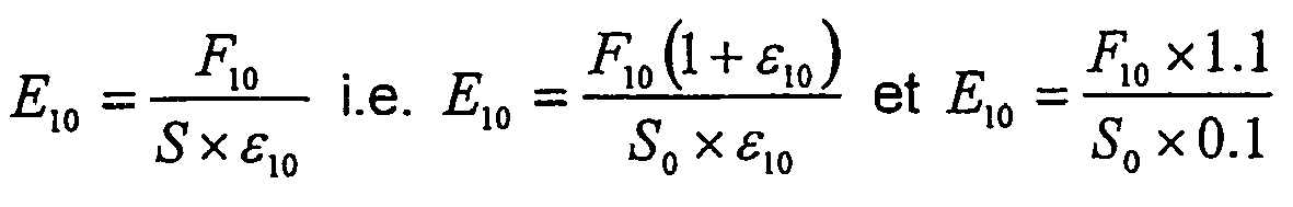
à 0.1 ;
avec E10 : module d'extension sécant à 10% de déformation ; F10: force d'extension à 10% d'extension ; S0: section initiale de l'éprouvette de test ; S : section de l'éprouvette de test à la déformation d'extension ε, dans le cas de matériau en caoutchouc, on sait que :
- « Tg » d'un élastomère, la température de transition vitreuse de celui-ci mesurée par analyse thermique différentielle;
- « test de fluage statique », un test dans lequel on prépare des éprouvettes dont la partie utile a une longueur de 70mm, une largeur de 5 mm et une épaisseur de 2,5 mm (ces éprouvettes sont découpées dans des plaques vulcanisées d'épaisseur 2,5 mm) ; on met en place les éprouvettes dans une étuve à 150°C et on leur accroche immédiatement une masse de 3 kg ; le test s'effectue ainsi avec une contrainte initiale de :

avec M : masse appliquée, g : accélération de la pesanteur et S0 section initiale de l'éprouvette de mesure ; on mesure en fonction du temps l'allongement de la partie utile de l'éprouvette ; le « taux de fluage statique » correspond à la variation de déformation dans un temps donné,par exemple entre 3 et 5 heures de test :
avec : Δε = ε(t2) - ε(t1) variation de la déformation mesurée pendant un intervalle de temps Δt = t2-t1 en minutes (mn) ; - « test de rhéométrie » : un test de cisaillement alterné à une déformation de ± 0,2 degrés, une fréquence de 100 cycles/mn, une température de 197°C et une durée de 10 mn ; rhéomètre de la société Monsanto ; le test est effectué sur un disque de mélange cru, on enregistre l'évolution pendant les 10 mn du couple résultant du cisaillement imposé entre les deux faces du disque ; on note particulièrement ici l'évolution du couple après le maximum mesuré, si le couple mesuré reste stable, il n'y a pas de réversion, c'est-à-dire de diminution de la raideur de l'éprouvette, si le couple mesuré diminue, on indique qu'il y a une réversion ; le phénomène de réversion traduit une diminution de la rigidité de l'éprouvette dans les conditions du test ; c'est un test de la stabilité thermique du mélange à haute température ; on note :

le taux de réversion à l'issue du test ; Cmax est le couple maximum mesuré et C10 est le couple mesuré après 10 mn de test ; - « un renfort orienté circonférentiellement », un renfort orienté sensiblement parallèlement à la direction circonférentielle du pneumatique, c'est-à-dire faisant avec cette direction un angle ne s'écartant pas de plus de cinq degrés de la direction circonférentielle ; et
- « un renfort orienté radialement », un renfort contenu sensiblement dans un même plan axial ou dans un plan faisant avec un plan axial un angle inférieur ou égal à 10 degrés.
-
- "Reinforcement", both monofilaments and multifilaments, or assemblies such as cables, twists or even any type of equivalent assembly, and this, whatever the material and the treatment of these reinforcements, for example surface treatment or coating or pre-gluing to promote adhesion to the rubber;
- "Contact" between a reinforcement and a rubber anchoring mixture, the fact that at least a portion of the outer contour of the reinforcement is in intimate contact with the rubber anchoring mixture; if the reinforcement comprises a coating or a coating, the term contact means that it is the outer contour of this coating or this coating which is in close contact with the rubber anchoring mixture;
- "Axial", a direction parallel to the axis of rotation of the tire; this direction can be "axially inner" when directed towards the inside of the tire and "axially outer" when it is directed towards the outside of the tire;
- "Radial" means a direction passing through the axis of rotation of the tire and normal to it; this direction may be "radially inner" or "radially outer" as it moves towards the axis of rotation of the tire or towards the outside of the tire;
- "Modulus of elasticity" of a rubber mix, a secant modulus of extension at 10% of deformation and at room temperature, the measurement being carried out after a first cycle of accommodation up to 10% of deformation:
-
at 0.1;
with E 10 : secant extension module at 10% deformation; F 10 : extension force at 10% extension; S 0 : initial section of the test specimen; S: section of the test specimen at extension strain ε, in the case of rubber material, it is known that: - "Tg" of an elastomer, the glass transition temperature thereof measured by differential thermal analysis;
- 'Static creep test' means a test in which test pieces are prepared, the useful part of which has a length of 70 mm, a width of 5 mm and a thickness of 2.5 mm (these test pieces are cut from thick vulcanised sheets 2.5 mm); the test pieces are placed in an oven at 150 ° C. and a weight of 3 kg is immediately attached to them; the test is thus carried out with an initial constraint of:
with M: applied mass, g: gravitational acceleration and S 0 initial section of the test specimen; we measure according to time the extension of the useful part of the test piece; the "static creep rate" corresponds to the variation of deformation in a given time, for example between 3 and 5 hours of test:
with: Δε = ε (t 2 ) - ε (t 1 ) variation of the strain measured during a time interval Δt = t 2 -t 1 in minutes (mn); - "Rheometry test" means an alternating shear test at a deformation of ± 0.2 degrees, a frequency of 100 cycles / min, a temperature of 197 ° C and a duration of 10 minutes; rheometer of the company Monsanto; the test is performed on a raw mixing disk, the evolution is recorded during the 10 minutes of the torque resulting from the shear imposed between the two faces of the disk; we note particularly here the evolution of the torque after the maximum measured, if the measured torque remains stable, there is no reversion, that is to say, decrease in the stiffness of the specimen, if the torque measured decreases, it is indicated that there is a reversion; the phenomenon of reversion reflects a decrease in the stiffness of the specimen under the conditions of the test; it is a test of the thermal stability of the mixture at high temperature; we notice :
the reversion rate at the end of the test; C max is the maximum torque measured and C 10 is the torque measured after 10 minutes of testing; - "A circumferentially oriented reinforcement", a reinforcement oriented substantially parallel to the circumferential direction of the tire, that is to say making with this direction an angle not deviating by more than five degrees from the circumferential direction; and
- "A radially oriented reinforcement", a reinforcement contained substantially in the same axial plane or in a plane forming with an axial plane an angle less than or equal to 10 degrees.
-
Dans la présente description, le terme "fil" désigne en toute généralité aussi bien des monofilaments que des multifilaments ou des assemblages comme des câbles, des retors ou encore tout type d'assemblage équivalent, et ceci, quels que soient la matière et le traitement de ces fils. Il peut s'agir par exemple de traitements de surface, enrobage ou pré-encollage pour favoriser l'adhérence sur le caoutchouc. L'expression « fil unitaire » désigne un fil composé d'un seul élément, sans assemblage. Le terme « multifilaments » désigne au contraire un assemblage d'au moins deux éléments unitaires pour former un câble, un retors, etc.In the present description, the term "wire" generally refers to both monofilaments and multifilaments or assemblies such as cables, twisted or even any type of equivalent assembly, and this, whatever the material and treatment of these son. It may be for example surface treatments, coating or pre-sizing to promote adhesion to the rubber. The term "unitary wire" refers to a single-component wire, without assembly. The term "multifilament" means on the contrary an assembly of at least two unitary elements to form a cable, a twist, etc.
D'autre part, on entend par structure radiale, un agencement à 90 degrés, mais aussi, selon l'usage, à un angle proche de 90°.On the other hand, radial structure means a 90-degree arrangement, but also, according to custom, at an angle close to 90 °.
On sait que, de façon traditionnelle, la ou les nappes de carcasse sont retournées autour d'une tringle. La tringle remplit alors une fonction d'ancrage de la carcasse. Ainsi, notamment, elle supporte la tension se développant dans les fils de carcasse par exemple sous l'effet de la pression de gonflage. L'agencement décrit dans le présent document permet d'assurer une fonction similaire d'ancrage. Il est également connu d'utiliser la tringle de type traditionnel pour assurer une fonction de serrage du bourrelet sur une jante. L'agencement décrit dans le présent document permet également d'assurer un rôle similaire de serrage.It is known that, traditionally, the carcass ply or plies are turned around a rod. The rod then performs a function of anchoring the carcass. Thus, in particular, it supports the tension developing in the carcass son for example under the effect of the inflation pressure. The arrangement described herein provides a similar anchoring function. It is also known to use the traditional type of rod to ensure a function of tightening the bead on a rim. The arrangement described in this document also provides a similar role of clamping.
Dans la présente description, on entend par gomme ou mélange de « liaison », le mélange caoutchoutique éventuellement en contact avec les fils de renforcement, adhérant à ceux-ci et susceptible de remplir les interstices entre fils adjacents.In the present description, the term gum or "bond" mixture is understood to mean the rubber mixture possibly in contact with the reinforcement threads, adhering thereto and capable of filling the interstices between adjacent yarns.
On désigne "flancs" les portions du pneumatique le plus souvent de faible rigidité de flexion situées entre le sommet et les bourrelets. On appelle "mélange flancs" les mélanges caoutchoutiques situés axialement extérieurement relativement aux fils de la structure de renforcement de la carcasse et à leur gomme de liaison. Ces mélanges ont habituellement un bas module d'élasticité."Flanks" designates the portions of the tire most often of low flexural stiffness located between the top and the beads. So-called "sidewall mixtures" rubber mixtures located axially externally relative to the son of the carcass reinforcement structure and their gum binding. These mixtures usually have a low modulus of elasticity.
On appelle "bourrelet" la portion du pneumatique adjacente radialement intérieurement au flanc.The portion of the tire adjacent radially to the sidewall is called "bead".
La
Le pneumatique comporte une structure de renfort de type carcasse 2, pourvue de renforts avantageusement configurés selon un agencement sensiblement radial. Cette structure peut être agencée de façon continue d'un bourrelet à l'autre, en passant par les flancs et le sommet, ou encore, elle peut comporter deux ou plusieurs parties, agencées par exemple le long des flancs, sans couvrir la totalité du sommet.The tire comprises a carcass-
Les portions d'extrémité 21 de la structure de renfort 2 sont situées dans les bourrelets.The
La structure de renfort 2 peut être réalisée par enroulement d'un seul fil faisant des aller-retours entre les deux bourrelets en formant dans chacun des bourrelets des boucles. Ces boucles, enrobées dans le mélange caoutchoutique, contribuent à la liaison mécanique entre la structure de renfort 2 et le bourrelet, notamment les piles 13. Par la présence de boucles entre le parcours "aller" et le "retour" du fil, on voit que le renforcement est de type monofilament. Bien entendu, la carcasse pourrait ne pas être fabriquée de façon continue à partir d'un seul fil, et il pourrait ne pas y avoir de boucles, mais par exemple des extrémités libres.The reinforcing
Le bourrelet comporte par ailleurs une zone d'ancrage 30 sensiblement circonférentielle et comprenant un arrangement de fils circonférentiels disposés de façon sensiblement adjacente à une portion de la structure de renfort et comprend au moins deux piles réparties de part et d'autre de la structure de renfort, un mélange de liaison (ou d'ancrage) étant disposé entre les fils circonférentiels et la structure de renfort.The bead further comprises a substantially
Dans la zone d'ancrage, au moins un fil 12 d'une des piles 13 est de préférence disposé à proximité immédiate d'une portion 21 de la structure de renfort 2. Les piles peuvent également être agencées de façon à ce qu'une portion 21 soit intercalée entre des piles 13.In the anchoring zone, at least one
Dans la zone d'ancrage, l'espace entre les fils 12 et la structure de renfort 2 est occupé par un mélange caoutchoutique de liaison 14. Le mélange caoutchouteux d'ancrage ou de liaison 14 est disposé de part et d'autre de la structure de renfort entre cette structure et les enroulements circonférentiels 12. Ce mélange caoutchouteux d'ancrage 14 est en contact direct avec au moins une portion du contour d'une part des éléments de renfort de la structure 2 et d'autre part des fils 12 présents dans la zone d'ancrage. Dans l'exemple présenté, le mélange caoutchouteux d'ancrage est en contact avec tous les fils ou renforts disposés dans la zone d'ancrage, et remplit les interstices entre ceux-ci. Ce contact direct entre le mélange caoutchouteux d'ancrage 9 et les éléments de renfort dans la zone d'ancrage est essentiel pour qu'il y ait une bonne coopération mécanique entre les fils circonférentiels et le mélange caoutchouteux d'ancrage pour ancrer solidement les éléments de la structure de renfort 2 dans la zone d'ancrage du bourrelet et reprendre les efforts subis par ces éléments dus notamment à la pression de gonflage du pneumatique. Le mélange caoutchouteux d'ancrage a comme caractéristique mécanique principale une excellente résistance au fluage associée à un module d'élasticité compris entre 10 et 20 MPaIn the anchoring zone, the space between the
Les fils 12 sont sensiblement inextensibles et peuvent être des câbles métalliques. Les éléments de la structure 2 peuvent être usuellement des renforts textiles de haut module d'élasticité, tels des renforts aramides.The
Les arrangements de fils 11 peuvent être agencés et fabriqués différemment. Par exemple, une pile 13 peut avantageusement être constituée d'un seul fil 12, enroulé (sensiblement à zéro degrés) en spirale, de préférence depuis le plus petit diamètre vers le plus grand diamètre. Une pile peut également être constituée de plusieurs fils concentriques posés l'un dans l'autre.The
Dans l'exemple de réalisation illustré à la
Le bourrelet comporte également une zone d'appui 50, disposée sensiblement entre la zone d'ancrage et le siège du bourrelet, sensiblement alignée axialement avec ces zones, ladite zone étant adaptée pour une mise en compression lors du montage du pneumatique sur une jante adaptée. Cette mise en compression contribue à assurer le serrage du pneumatique, en transmettant l'effort de serrage produit par la zone de serrage. Le mélange caoutchoutique de cette zone est sélectionné de façon à procurer une bonne résistance au fluage, afin d'assurer la pérennité des caractéristiques de serrage.The bead also comprises a
Une zone latérale extérieure 17 est prévue dans la zone du bourrelet prévue pour être disposée entre le rebord ou crochet 60 de jante et la zone d'ancrage. Cette zone est meublée de préférence par un mélange caoutchoutique de sensiblement haut module, par exemple compris entre 10 et 40 MPa.An
Cette zone permet d'augmenter la pression de serrage, notamment dans la région du crochet de jante. Grâce à sa déformabilité réduite, elle permet de limiter la tendance du bourrelet à glisser radialement extérieurement au-delà du crochet de jante. Elle contribue par ailleurs d'une part à inhiber toute tendance à générer un moment de rotation, et d'autre part à établir une stabilité dynamique, comme par exemple lors de virages ou de sollicitations latérales importantes.This zone makes it possible to increase the clamping pressure, especially in the region of the rim hook. Thanks to its reduced deformability, it limits the tendency of the bead to slide radially outwardly beyond the rim hook. It also contributes, on the one hand, to inhibiting any tendency to generate a moment of rotation, and on the other hand to establishing a dynamic stability, such as during sharp turns or lateral stresses.
De manière avantageuse, la zone latérale extérieure 17 est prévue dans la portion axialement externe du bourrelet et s'étend entre la portion adjacente au crochet de jante et la zone d'ancrage. Elle coopère avantageusement avec la zone d'ancrage, ce qui permet une meilleure action mécanique entre ladite zone d'ancrage et la portion du bourrelet adjacente au crochet de jante.Advantageously, the
Le pneumatique selon l'invention est particulièrement adapté pour être utilisé sur une jante du type de celle décrite dans le document
Les bases des piles (les fils radialement les plus près de l'axe de rotation du pneumatique) sont de préférence disposées radialement plus à l'extérieur que l'extrémité dudit rebord (portion axialement et radialement la plus à l'extérieur dudit rebord) tel qu'illustré par exemple à la
Les différents exemples de réalisations décrites et/ou illustrées peuvent avantageusement être réalisées avec des dispositifs du type de ceux décrits dans le document
Ainsi par exemple, il est très avantageux de confectionner le pneumatique sur un noyau central imposant la forme de sa cavité intérieure. On applique sur ce noyau, de préférence dans l'ordre requis par l'architecture finale, tous les constituants du pneumatique, qui sont disposés directement à leur place finale, selon un profil sensiblement final. Dans ce cas, un tel pneumatique peut être moulé et vulcanisé comme exposé dans le document
La
En variante beaucoup d'autres modes de réalisation pour notamment la structure de renfort de type carcasse peuvent être utilisés. A titre d'exemple, au lieu d'utiliser un fil continu formant des boucles dans le bourrelet, on peut utiliser des fils individuels posés successivement ou par groupe de quelques-uns formant une bandelette.In a variant, many other embodiments, in particular for the carcass-type reinforcement structure, may be used. By way of example, instead of using a continuous wire forming loops in the bead, it is possible to use individual wires laid successively or in groups of a few forming a strip.
Le mélange caoutchouteux d'ancrage ou de liaison selon l'invention a donc comme caractéristiques mécaniques essentielles une rigidité telle que son module d'extension à 10 % de déformation est compris entre 10 et 20 MPa, une excellente résistance au fluage à haute température et une très bonne stabilité à haute température. La rigidité choisie donne aux structures de bourrelet décrites une souplesse suffisante pour permettre de réaliser aisément les montages et démontages des pneumatiques, même ceux de grandes dimensions, sur leurs jantes de service sans dégrader les performances d'endurance ; la résistance au fluage est essentielle pour obtenir un ancrage solide et durable des armatures de carcasse dans les bourrelets et la stabilité thermique à haute température est elle aussi importante en raison des conditions thermiques très sévères que peuvent subir en service certains bourrelets de pneumatiques.The anchoring or bonding rubber mix according to the invention therefore has as its essential mechanical characteristics a rigidity such that its 10% strain extension module is between 10 and 20 MPa, excellent resistance to creep at high temperature and very good stability at high temperature. The rigidity chosen gives the bead structures described sufficient flexibility to allow easy assembly and disassembly of tires, even those of large dimensions, on their service rims without degrading endurance performance; the creep resistance is essential to obtain a solid and durable anchoring of the carcass reinforcement in the beads and high temperature thermal stability is also important because of the very severe thermal conditions that may be experienced in service some tire beads.
Les expérimentations ont montré que pour obtenir de bons résultats en endurance, on peut utiliser un mélange caoutchouteux d'ancrage contenant un élastomère synthétique SBR de Tg comprise entre -70 et -30°C, utilisé seul ou en couplage avec du polybutadiène. De préférence le polybutadiène a une Tg comprise entre -110 et -90°C. Le ou les élastomères synthétiques sont utilisés en proportion totalisée d'au moins 50% du poids total d'élastomères, le solde est constitué par du caoutchouc naturel. Le mélange caoutchouteux d'ancrage contient en plus des charges de renforcement tel du noir de carbone et un système de vulcanisation appropriés pour obtenir la rigidité désirée. Les fils 12 sont, dans les exemples présentés, des câbles métalliques laitonnés. Il est donc préférable que le mélange caoutchouteux d'ancrage ait un taux de soufre important et contienne des additifs promoteurs de l'adhésion avec le laiton (par exemple des sels métalliques de cobalt ou de nickel). On utilise par exemple un taux de soufre compris entre 5 et 8 % du poids total d'élastomère et un taux de noir de carbone compris entre 60 et 70 % du poids total d'élastomère. Le noir de carbone N347 peut être utilisé préférentiellement.Experiments have shown that to obtain good endurance results, it is possible to use a rubber anchoring mixture containing a SBR synthetic elastomer of Tg between -70 and -30 ° C., used alone or in coupling with polybutadiene. Preferably the polybutadiene has a Tg between -110 and -90 ° C. The synthetic elastomer or elastomers are used in a totalized proportion of at least 50% of the total weight of elastomers, the balance being constituted by natural rubber. The rubber anchor mixture additionally contains reinforcing fillers such as carbon black and a vulcanizing system suitable for obtaining the desired rigidity. The
Quatre mélanges ont été réalisés et testés pour illustrer les caractéristiques des mélange caoutchouteux d'ancrage selon l'invention.Four mixtures were made and tested to illustrate the characteristics of the anchoring rubber mixes according to the invention.
Les composants principaux de la formulation de ces mélanges se trouvent dans le tableau ci-dessous.
Ces quatre mélanges ont été testés ainsi :
- rigidité : détermination du module d'élasticité à 10 % d'extension et température ambiante,
- fluage : test de fluage statique à 150°C pendant 7 heures comme décrit précédemment, et
- stabilité thermique : test de rhéométrie à 197°C pendant 10 mn tel que décrit précédemment.
- rigidity: determination of the modulus of elasticity at 10% extension and ambient temperature,
creep: static creep test at 150 ° C. for 7 hours as described previously, and
thermal stability: Rheometry test at 197 ° C. for 10 minutes as described above.
Les quatre mélanges ont une rigidité satisfaisante.The four mixtures have a satisfactory rigidity.
La
Le mélange 2 a des résultats améliorés relativement au premier mais n'est pas non plus satisfaisant.
Les mélanges 3 et 4 passent avec succès les tests de fluage statique et de rhéométrie. Leur résistance au fluage est tout à fait correcte et leur stabilité thermique à haute température aussi. Le mélange 3, qui comporte trois élastomères, présente un résultat légèrement plus satisfaisant en réversion que le mélange 4.
Des essais pneumatiques ont aussi été réalisés avec des mélanges caoutchouteux d'ancrage de formulations similaires aux mélanges de l'essai. Les pneumatiques ont montré une aptitude correcte pour les opérations de montage et de démontage, mais seuls ceux comportant un mélange caoutchouteux d'ancrage correspondant aux formulations des mélanges 3 et 4 ont montré une résistance en endurance de l'ancrage de la structure de renfort de type carcasse dans les bourrelets suffisante.Pneumatic tests were also performed with rubber mixes anchoring similar formulations to the test mixtures. The tires showed a correct aptitude for assembly and disassembly operations, but only those comprising a rubber anchoring mixture corresponding to the formulations of the
A titre non limitatif, il est à noter que la confection des pneumatiques selon l'invention peut avantageusement être réalisée selon un procédé n'impliquant pas ou peu de transformations de formes à l'état cru. Par exemple, on peut assembler l'ébauche du futur pneumatique sur un noyau central imposant la forme de sa cavité intérieure. On applique sur ce noyau, dans l'ordre requis par l'architecture finale, tous les constituants du pneumatique, qui sont disposés directement à leur place finale, sans subir de conformation à aucun moment de la confection. Cette confection peut notamment utiliser les dispositifs décrits dans le brevet
Claims (15)
- A tyre for a vehicle wheel, comprising:- two sidewalls spaced apart axially from each other, joined at their radially outer portions by a crown zone provided on its radially outer portion with a circumferential tread;- beads, arranged radially to the inside of each of the sidewalls, each bead comprising a seat and an outer flange which are intended to come into contact with a suitable rim;- a reinforcement structure extending substantially radially from each of the beads, along the sidewalls, towards the crown zone;- at least one of said beads comprising:- a bead seat comprising a generatrix the axially inner end of which is located on a circle of diameter greater than the diameter of the circle on which the axially outer end is located;- a bearing zone for said bead extending substantially along the seat of the latter;- an anchoring zone for the reinforcement structure in said bead, comprising an arrangement of circumferential threads arranged substantially adjacent to a portion of the reinforcement structure and comprising at least two stacks distributed on either side of the reinforcement structure, a bonding mix being arranged between the circumferential threads and the reinforcement structure;characterised in that :- said bonding mix of the anchoring zone has a elasticity modulus at a deformation of 10% of less than 20 MPa and preferably between 10 and 20 MPa;- an axially outer zone is arranged in the zone of the bead provided to be arranged between the rim hook and the anchoring zone, said zone being furnished by a rubber mix of elasticity modulus at a deformation of 10% substantially higher than that of said anchoring zone.
- A tyre according to Claim 1, in which said bonding rubber mix comprises at least one synthetic elastomer included in the group of SBRs and polybutadienes with a total proportion of synthetic elastomer greater than 50% of the total weight of elastomers.
- A tyre according to Claim 2, in which the total proportion of synthetic elastomer is of between 55% and 65%.
- A tyre according to one of Claims 1 to 3, in which the anchoring rubber mix comprises an SBR of a Tg of between -70 and -25°C with a proportion by weight greater than 20% of the total weight of elastomers.
- A tyre according to one of Claims 1 to 4, in which the anchoring rubber mix comprises a polybutadiene of a Tg of between -110 and -90°C with a proportion by weight less than 40% of the total weight of elastomers.
- A tyre according to one of Claims 1 to 5, in which the anchoring rubber mix withstands without breaking a static creep stress at 150°C under an initial stress of 2.35 MPa for at least 5 hours.
- A tyre according to one of Claims 1 to 6, in which said anchoring rubber mix has an amount of static creep at 150°C under an initial stress of 2.35 MPa of less than 2x10⁻³/min between 3 and 5 hours' stress.
- A tyre according to one of Claims 1 to 7, in which said anchoring rubber mix has an amount of reversion after 10 min at 197°C of less than 10%.
- A tyre according to Claim 8, in which said anchoring rubber mix has an amount of reversion after 10 min at 197°C of less than 5%.
- A tyre for a vehicle wheel according to one of the preceding claims, in which the elasticity modulus at a deformation of 10% of the rubber mix of the external lateral zone is greater than 30 MPa and preferably greater than 40 MPa.
- A tyre for a vehicle wheel according to one of the preceding claims, in which the external lateral zone cooperates with the anchoring zone.
- A tyre for a vehicle wheel according to one of the preceding claims, in which the rubber mix of the anchoring zone is in contact on one hand with the circumferential threads, and on the other hand with the carcass-type reinforcement structure.
- A tyre for a vehicle wheel according to one of the preceding claims, furthermore comprising an anti-creep zone arranged at the level of the bead, substantially along the carcass-type reinforcement structure.
- A tyre for a vehicle wheel according to Claim 13, in which the rubber mix of the anti-creep zone has an elasticity modulus at a deformation of 10% greater than that of the mix of the anchoring zone.
- A tyre for a vehicle wheel according to Claim 13, in which the rubber mix of the anti-creep zone has an elasticity modulus at a deformation of 10% greater than 30 MPa and preferably greater than 40 MPa.
Applications Claiming Priority (3)
| Application Number | Priority Date | Filing Date | Title |
|---|---|---|---|
| FR0214483 | 2002-11-18 | ||
| FR0214483A FR2847203A1 (en) | 2002-11-18 | 2002-11-18 | Pneumatic tire for motor vehicle, comprising at least one bead with a seat which has on it's inner edge a circle of larger diameter than the outer edge |
| PCT/EP2003/011992 WO2004045873A1 (en) | 2002-11-18 | 2003-10-29 | Tyre with extended mobility with substantially low-modulus anchoring zone |
Publications (2)
| Publication Number | Publication Date |
|---|---|
| EP1565329A1 EP1565329A1 (en) | 2005-08-24 |
| EP1565329B1 true EP1565329B1 (en) | 2008-04-16 |
Family
ID=32187741
Family Applications (1)
| Application Number | Title | Priority Date | Filing Date |
|---|---|---|---|
| EP03758080A Expired - Lifetime EP1565329B1 (en) | 2002-11-18 | 2003-10-29 | Tyre with extended mobility with substantially low-modulus anchoring zone |
Country Status (10)
| Country | Link |
|---|---|
| US (1) | US7051779B2 (en) |
| EP (1) | EP1565329B1 (en) |
| JP (1) | JP2006506265A (en) |
| KR (1) | KR20050070139A (en) |
| CN (1) | CN100343082C (en) |
| AT (1) | ATE392316T1 (en) |
| AU (1) | AU2003274093A1 (en) |
| DE (1) | DE60320443T2 (en) |
| FR (1) | FR2847203A1 (en) |
| WO (1) | WO2004045873A1 (en) |
Families Citing this family (1)
| Publication number | Priority date | Publication date | Assignee | Title |
|---|---|---|---|---|
| JP2007083775A (en) * | 2005-09-20 | 2007-04-05 | Bridgestone Corp | Pneumatic tire |
Family Cites Families (10)
| Publication number | Priority date | Publication date | Assignee | Title |
|---|---|---|---|---|
| US1803693A (en) * | 1929-04-24 | 1931-05-05 | Herbert A Cutting | Cleaning means |
| US4119386A (en) * | 1976-06-10 | 1978-10-10 | Cushing Ernest W | Mop assembly to distribute selected liquids on floor areas, to be waxed, cleaned, and/or stripped |
| FR2736006A1 (en) * | 1995-06-29 | 1997-01-03 | Sedepro | TIRE COMPRISING CIRCUMFERENTIAL CABLES FOR ANCHORING THE CARCASS, PROCESS FOR PREPARING SUCH CABLES |
| JP4184445B2 (en) * | 1997-05-27 | 2008-11-19 | コンパニー ゼネラール デ エタブリッスマン ミシュラン−ミシュラン エ コムパニー | Tire carcass locking structure |
| WO1999064225A1 (en) * | 1998-06-05 | 1999-12-16 | Pirelli Pneumatici S.P.A. | Method for manufacturing a tyre for vehicle wheels, tyre which can be obtained by said method, and vehicle wheel comprising said tyre |
| ATE298674T1 (en) * | 1999-12-03 | 2005-07-15 | Michelin Soc Tech | BEAD FOR FLAT TIRES |
| ATE301045T1 (en) * | 1999-12-03 | 2005-08-15 | Michelin Soc Tech | EXTENDED MOBILITY TIRE BEAD |
| US20020186996A1 (en) * | 2001-06-12 | 2002-12-12 | Aramark Corporation | Dispenser |
| US20030041406A1 (en) * | 2001-09-06 | 2003-03-06 | Lambert Wu | Vapor cleaner |
| DE10229327B4 (en) * | 2002-06-29 | 2009-06-25 | Avet Ag | cleaner |
-
2002
- 2002-11-18 FR FR0214483A patent/FR2847203A1/en active Pending
-
2003
- 2003-10-29 JP JP2004552497A patent/JP2006506265A/en active Pending
- 2003-10-29 CN CNB2003801035741A patent/CN100343082C/en not_active Expired - Fee Related
- 2003-10-29 AT AT03758080T patent/ATE392316T1/en not_active IP Right Cessation
- 2003-10-29 AU AU2003274093A patent/AU2003274093A1/en not_active Abandoned
- 2003-10-29 WO PCT/EP2003/011992 patent/WO2004045873A1/en active IP Right Grant
- 2003-10-29 KR KR1020057008905A patent/KR20050070139A/en not_active Application Discontinuation
- 2003-10-29 DE DE60320443T patent/DE60320443T2/en not_active Expired - Lifetime
- 2003-10-29 EP EP03758080A patent/EP1565329B1/en not_active Expired - Lifetime
-
2005
- 2005-05-18 US US11/131,414 patent/US7051779B2/en not_active Expired - Fee Related
Also Published As
| Publication number | Publication date |
|---|---|
| FR2847203A1 (en) | 2004-05-21 |
| WO2004045873A1 (en) | 2004-06-03 |
| AU2003274093A1 (en) | 2004-06-15 |
| US7051779B2 (en) | 2006-05-30 |
| CN100343082C (en) | 2007-10-17 |
| US20050263232A1 (en) | 2005-12-01 |
| EP1565329A1 (en) | 2005-08-24 |
| ATE392316T1 (en) | 2008-05-15 |
| JP2006506265A (en) | 2006-02-23 |
| KR20050070139A (en) | 2005-07-05 |
| DE60320443D1 (en) | 2008-05-29 |
| CN1714006A (en) | 2005-12-28 |
| DE60320443T2 (en) | 2009-05-07 |
Similar Documents
| Publication | Publication Date | Title |
|---|---|---|
| EP1237739B1 (en) | Tyre bead with extended mobility | |
| EP1299256B1 (en) | Aircraft tyre with improved tyre bead | |
| EP1254034B1 (en) | Tyre bead with extended mobility | |
| EP1299253B1 (en) | Tyre with improved carcass reinforcement anchoring structure | |
| EP2384910A2 (en) | Equipped assemblies for airplanes, wheels and tyres | |
| EP1461215A1 (en) | Double half-carcass tyre with an adapted crown area | |
| EP1554133B1 (en) | Extended mobility tyre comprising bead with symmetrical force distribution | |
| EP1299255B1 (en) | Tyre with improved carcass reinforcement anchoring structure | |
| EP1277600B1 (en) | Tyre carcass anchoring | |
| EP1299254B1 (en) | Tyre with improved carcass reinforcement anchoring structure | |
| EP1565329B1 (en) | Tyre with extended mobility with substantially low-modulus anchoring zone | |
| EP1789266B1 (en) | Extended mobility tyre comprising several superlow anchor areas | |
| EP0869017B1 (en) | Tyre with improved carcass | |
| EP1578622B1 (en) | Aircraft tyre | |
| EP1560720B1 (en) | Long use tyre with disengaged anchoring area | |
| EP2150423B1 (en) | Tyre for vehicle including reinforcements in the sidewalls | |
| EP1663672B1 (en) | Tyre with extended mobility with asymmetrically arranged beads | |
| WO2003093034A2 (en) | Tyre with bead provided with a wire structure divided into two zones | |
| WO2003093032A1 (en) | Tyre with bead comprising a micro-deformable anchor zone | |
| FR2858804A1 (en) | Aircraft wheel and tyre assembly uses one-piece weel rim with seats sloping at over 5 degrees and tyre with beads that can move out of round and warp | |
| WO2003093033A1 (en) | Tyre with bead provided with a zone facilitating mounting/dismounting | |
| WO2005047027A1 (en) | Tyre with extended mobility comprising dual reinforcement and asymmetric beads | |
| FR3103732A1 (en) | ASSEMBLY INCLUDING AN ADAPTABLE SUPPORTING STRUCTURE | |
| EP1883545B1 (en) | Tires for two-wheeled vehicles |
Legal Events
| Date | Code | Title | Description |
|---|---|---|---|
| PUAI | Public reference made under article 153(3) epc to a published international application that has entered the european phase |
Free format text: ORIGINAL CODE: 0009012 |
|
| 17P | Request for examination filed |
Effective date: 20050620 |
|
| AK | Designated contracting states |
Kind code of ref document: A1 Designated state(s): AT BE BG CH CY CZ DE DK EE ES FI FR GB GR HU IE IT LI LU MC NL PT RO SE SI SK TR |
|
| AX | Request for extension of the european patent |
Extension state: AL LT LV MK |
|
| DAX | Request for extension of the european patent (deleted) | ||
| GRAP | Despatch of communication of intention to grant a patent |
Free format text: ORIGINAL CODE: EPIDOSNIGR1 |
|
| GRAS | Grant fee paid |
Free format text: ORIGINAL CODE: EPIDOSNIGR3 |
|
| GRAA | (expected) grant |
Free format text: ORIGINAL CODE: 0009210 |
|
| AK | Designated contracting states |
Kind code of ref document: B1 Designated state(s): AT BE BG CH CY CZ DE DK EE ES FI FR GB GR HU IE IT LI LU MC NL PT RO SE SI SK TR |
|
| REG | Reference to a national code |
Ref country code: CH Ref legal event code: EP |
|
| REG | Reference to a national code |
Ref country code: IE Ref legal event code: FG4D Free format text: LANGUAGE OF EP DOCUMENT: FRENCH |
|
| REF | Corresponds to: |
Ref document number: 60320443 Country of ref document: DE Date of ref document: 20080529 Kind code of ref document: P |
|
| PG25 | Lapsed in a contracting state [announced via postgrant information from national office to epo] |
Ref country code: SI Free format text: LAPSE BECAUSE OF FAILURE TO SUBMIT A TRANSLATION OF THE DESCRIPTION OR TO PAY THE FEE WITHIN THE PRESCRIBED TIME-LIMIT Effective date: 20080416 |
|
| NLV1 | Nl: lapsed or annulled due to failure to fulfill the requirements of art. 29p and 29m of the patents act | ||
| PG25 | Lapsed in a contracting state [announced via postgrant information from national office to epo] |
Ref country code: PT Free format text: LAPSE BECAUSE OF FAILURE TO SUBMIT A TRANSLATION OF THE DESCRIPTION OR TO PAY THE FEE WITHIN THE PRESCRIBED TIME-LIMIT Effective date: 20080916 Ref country code: NL Free format text: LAPSE BECAUSE OF FAILURE TO SUBMIT A TRANSLATION OF THE DESCRIPTION OR TO PAY THE FEE WITHIN THE PRESCRIBED TIME-LIMIT Effective date: 20080416 Ref country code: FI Free format text: LAPSE BECAUSE OF FAILURE TO SUBMIT A TRANSLATION OF THE DESCRIPTION OR TO PAY THE FEE WITHIN THE PRESCRIBED TIME-LIMIT Effective date: 20080416 Ref country code: ES Free format text: LAPSE BECAUSE OF FAILURE TO SUBMIT A TRANSLATION OF THE DESCRIPTION OR TO PAY THE FEE WITHIN THE PRESCRIBED TIME-LIMIT Effective date: 20080727 Ref country code: BG Free format text: LAPSE BECAUSE OF FAILURE TO SUBMIT A TRANSLATION OF THE DESCRIPTION OR TO PAY THE FEE WITHIN THE PRESCRIBED TIME-LIMIT Effective date: 20080716 |
|
| PG25 | Lapsed in a contracting state [announced via postgrant information from national office to epo] |
Ref country code: AT Free format text: LAPSE BECAUSE OF FAILURE TO SUBMIT A TRANSLATION OF THE DESCRIPTION OR TO PAY THE FEE WITHIN THE PRESCRIBED TIME-LIMIT Effective date: 20080416 |
|
| REG | Reference to a national code |
Ref country code: IE Ref legal event code: FD4D |
|
| PG25 | Lapsed in a contracting state [announced via postgrant information from national office to epo] |
Ref country code: CZ Free format text: LAPSE BECAUSE OF FAILURE TO SUBMIT A TRANSLATION OF THE DESCRIPTION OR TO PAY THE FEE WITHIN THE PRESCRIBED TIME-LIMIT Effective date: 20080416 Ref country code: DK Free format text: LAPSE BECAUSE OF FAILURE TO SUBMIT A TRANSLATION OF THE DESCRIPTION OR TO PAY THE FEE WITHIN THE PRESCRIBED TIME-LIMIT Effective date: 20080416 Ref country code: IE Free format text: LAPSE BECAUSE OF FAILURE TO SUBMIT A TRANSLATION OF THE DESCRIPTION OR TO PAY THE FEE WITHIN THE PRESCRIBED TIME-LIMIT Effective date: 20080416 Ref country code: SE Free format text: LAPSE BECAUSE OF FAILURE TO SUBMIT A TRANSLATION OF THE DESCRIPTION OR TO PAY THE FEE WITHIN THE PRESCRIBED TIME-LIMIT Effective date: 20080716 |
|
| PLBE | No opposition filed within time limit |
Free format text: ORIGINAL CODE: 0009261 |
|
| STAA | Information on the status of an ep patent application or granted ep patent |
Free format text: STATUS: NO OPPOSITION FILED WITHIN TIME LIMIT |
|
| PG25 | Lapsed in a contracting state [announced via postgrant information from national office to epo] |
Ref country code: SK Free format text: LAPSE BECAUSE OF FAILURE TO SUBMIT A TRANSLATION OF THE DESCRIPTION OR TO PAY THE FEE WITHIN THE PRESCRIBED TIME-LIMIT Effective date: 20080416 Ref country code: RO Free format text: LAPSE BECAUSE OF FAILURE TO SUBMIT A TRANSLATION OF THE DESCRIPTION OR TO PAY THE FEE WITHIN THE PRESCRIBED TIME-LIMIT Effective date: 20080416 |
|
| 26N | No opposition filed |
Effective date: 20090119 |
|
| PGFP | Annual fee paid to national office [announced via postgrant information from national office to epo] |
Ref country code: IT Payment date: 20081022 Year of fee payment: 6 |
|
| BERE | Be: lapsed |
Owner name: MICHELIN RECHERCHE ET TECHNIQUE S.A. Effective date: 20081031 Owner name: SOC. DE TECHNOLOGIE MICHELIN Effective date: 20081031 |
|
| PG25 | Lapsed in a contracting state [announced via postgrant information from national office to epo] |
Ref country code: EE Free format text: LAPSE BECAUSE OF FAILURE TO SUBMIT A TRANSLATION OF THE DESCRIPTION OR TO PAY THE FEE WITHIN THE PRESCRIBED TIME-LIMIT Effective date: 20080416 |
|
| PGFP | Annual fee paid to national office [announced via postgrant information from national office to epo] |
Ref country code: FR Payment date: 20081014 Year of fee payment: 6 |
|
| PG25 | Lapsed in a contracting state [announced via postgrant information from national office to epo] |
Ref country code: MC Free format text: LAPSE BECAUSE OF NON-PAYMENT OF DUE FEES Effective date: 20081031 |
|
| REG | Reference to a national code |
Ref country code: CH Ref legal event code: PL |
|
| GBPC | Gb: european patent ceased through non-payment of renewal fee |
Effective date: 20081029 |
|
| PG25 | Lapsed in a contracting state [announced via postgrant information from national office to epo] |
Ref country code: BE Free format text: LAPSE BECAUSE OF NON-PAYMENT OF DUE FEES Effective date: 20081031 Ref country code: CY Free format text: LAPSE BECAUSE OF FAILURE TO SUBMIT A TRANSLATION OF THE DESCRIPTION OR TO PAY THE FEE WITHIN THE PRESCRIBED TIME-LIMIT Effective date: 20080416 |
|
| PG25 | Lapsed in a contracting state [announced via postgrant information from national office to epo] |
Ref country code: LI Free format text: LAPSE BECAUSE OF NON-PAYMENT OF DUE FEES Effective date: 20081031 Ref country code: CH Free format text: LAPSE BECAUSE OF NON-PAYMENT OF DUE FEES Effective date: 20081031 |
|
| PG25 | Lapsed in a contracting state [announced via postgrant information from national office to epo] |
Ref country code: GB Free format text: LAPSE BECAUSE OF NON-PAYMENT OF DUE FEES Effective date: 20081029 |
|
| REG | Reference to a national code |
Ref country code: FR Ref legal event code: ST Effective date: 20100630 |
|
| PG25 | Lapsed in a contracting state [announced via postgrant information from national office to epo] |
Ref country code: HU Free format text: LAPSE BECAUSE OF FAILURE TO SUBMIT A TRANSLATION OF THE DESCRIPTION OR TO PAY THE FEE WITHIN THE PRESCRIBED TIME-LIMIT Effective date: 20081017 Ref country code: LU Free format text: LAPSE BECAUSE OF NON-PAYMENT OF DUE FEES Effective date: 20081029 Ref country code: FR Free format text: LAPSE BECAUSE OF NON-PAYMENT OF DUE FEES Effective date: 20091102 |
|
| PG25 | Lapsed in a contracting state [announced via postgrant information from national office to epo] |
Ref country code: TR Free format text: LAPSE BECAUSE OF FAILURE TO SUBMIT A TRANSLATION OF THE DESCRIPTION OR TO PAY THE FEE WITHIN THE PRESCRIBED TIME-LIMIT Effective date: 20080416 |
|
| PG25 | Lapsed in a contracting state [announced via postgrant information from national office to epo] |
Ref country code: GR Free format text: LAPSE BECAUSE OF FAILURE TO SUBMIT A TRANSLATION OF THE DESCRIPTION OR TO PAY THE FEE WITHIN THE PRESCRIBED TIME-LIMIT Effective date: 20080717 |
|
| PGFP | Annual fee paid to national office [announced via postgrant information from national office to epo] |
Ref country code: DE Payment date: 20101022 Year of fee payment: 8 |
|
| PG25 | Lapsed in a contracting state [announced via postgrant information from national office to epo] |
Ref country code: IT Free format text: LAPSE BECAUSE OF NON-PAYMENT OF DUE FEES Effective date: 20091029 |
|
| PG25 | Lapsed in a contracting state [announced via postgrant information from national office to epo] |
Ref country code: DE Free format text: LAPSE BECAUSE OF NON-PAYMENT OF DUE FEES Effective date: 20120501 |
|
| REG | Reference to a national code |
Ref country code: DE Ref legal event code: R119 Ref document number: 60320443 Country of ref document: DE Effective date: 20120501 |