EP1565282B1 - Method and apparatus for spinning to a constant lenght - Google Patents
Method and apparatus for spinning to a constant lenght Download PDFInfo
- Publication number
- EP1565282B1 EP1565282B1 EP03781956A EP03781956A EP1565282B1 EP 1565282 B1 EP1565282 B1 EP 1565282B1 EP 03781956 A EP03781956 A EP 03781956A EP 03781956 A EP03781956 A EP 03781956A EP 1565282 B1 EP1565282 B1 EP 1565282B1
- Authority
- EP
- European Patent Office
- Prior art keywords
- mandrel
- spinning
- shoulder
- diameter
- tubular member
- Prior art date
- Legal status (The legal status is an assumption and is not a legal conclusion. Google has not performed a legal analysis and makes no representation as to the accuracy of the status listed.)
- Expired - Lifetime
Links
- 238000009987 spinning Methods 0.000 title claims abstract description 49
- 238000000034 method Methods 0.000 title claims abstract description 37
- 239000000463 material Substances 0.000 claims abstract description 67
- 239000000758 substrate Substances 0.000 claims description 6
- 230000003197 catalytic effect Effects 0.000 claims description 5
- 230000007704 transition Effects 0.000 description 11
- 238000004519 manufacturing process Methods 0.000 description 2
- 238000003825 pressing Methods 0.000 description 2
- 230000006835 compression Effects 0.000 description 1
- 238000007906 compression Methods 0.000 description 1
- 230000001276 controlling effect Effects 0.000 description 1
- 230000002596 correlated effect Effects 0.000 description 1
- 238000002789 length control Methods 0.000 description 1
- 239000002184 metal Substances 0.000 description 1
- 239000007769 metal material Substances 0.000 description 1
- 238000005096 rolling process Methods 0.000 description 1
- 238000003466 welding Methods 0.000 description 1
Images


Classifications
-
- B—PERFORMING OPERATIONS; TRANSPORTING
- B21—MECHANICAL METAL-WORKING WITHOUT ESSENTIALLY REMOVING MATERIAL; PUNCHING METAL
- B21D—WORKING OR PROCESSING OF SHEET METAL OR METAL TUBES, RODS OR PROFILES WITHOUT ESSENTIALLY REMOVING MATERIAL; PUNCHING METAL
- B21D22/00—Shaping without cutting, by stamping, spinning, or deep-drawing
- B21D22/14—Spinning
- B21D22/16—Spinning over shaping mandrels or formers
Definitions
- the present invention relates a method and an apparatus for spinning a material to a circumferential configuration, according to the preamble of claims 1 and 15 respectively.
- a spinning machine including a plurality of chuck jaws, which confixedly hold material to be spun, such as a tubular member.
- the tubular member is spun in the chuck and a roller is moved transversely of the longitudinal length of the material, such that the roller engages the tube.
- the roller is then moved in an axis parallel to the longitudinal axis of the tubular member. In this way, the material of the tubular member can be formed into various configurations, such as a reduced diameter neck portion.
- a method of spinning a material to a circumferential configuration having a constant length comprises the steps of providing a tubular material to be spun; providing a tooling roller and moving it tangentially towards the material; causing relative rotational movement between the roller and the material; and moving the roller along an axis parallel to the longitudinal axis, thereby spinning the material to a radially different configuration.
- the objects of the invention have been accomplished by providing a method of spinning a material to a circumferential configuration having a constant length, according to claim 1.
- Patent Abstracts of Japan publication number JP 02 070327 A discloses the spinning of pipe material.
- a core bar is inserted into the pipe material.
- the outer diameter of the bar is sized approximately equal to the desired inner diameter of the fully formed pipe.
- the pipe material is rotated about a central axis, and then a spinning roller is brought into contact with the outer surface of the pipe material to form the pipe material.
- the apparatus also includes a stopper separated from the roller by a distance "L". As the roller travels along the pipe material, the roller forms the pipe material to reduce the diameter.
- the roller forms a length of the pipe material approximately equal to the distance "L” until a stopper comes into contact with the end of the pipe material. Once the stopper contacts the pipe material, the roller continues travelling along the pipe material while the stopper remains in contact with pipe material, thereby increasing the distance separating the roller and the stopper.
- Patent Abstract of Japan Patent publication number JP 06 182471 A discloses a method for forming an automobile wheel utilizing a spinning roller to press a portion of a forming material onto a mandrel.
- the spinning roller deforms the forming material against the mandrel until a given position is reached. Once the roller reaches the desired position, the roller transversely moves toward the forming material in order to form an outer periphery flange in the forming material.
- DE 503 592 discloses a method of making insert dishes for centrifuges.
- the insert dishes consist of a thin conical shell with thicker flanges connected thereto and are made of sheet metal.
- the method disclosed involves displacing the sheet metal material resulting in a reduced material thickness by pressing a rolling wheel onto a portion of the material against a die.
- the material takes the shape of the outer surface of the die during this spinning process.
- the end of the material has a thickness greater than the remainder of the material.
- the shoulder is provided as a transverse plane, transverse to the longitudinal axis.
- the shoulder can be provided in the form of a mandrel.
- the mandrel can be provided in a dimension generally along the longitudinal axis, having a first end portion with a constant first end diameter to extend below the free end edges, and a second diameter, spaced from the first end diameter, and having a diameter larger than the first end diameter forming the shoulder therebetween.
- the material can be provided tubular in shape.
- the material can be held by a chuck, where the chuck spins about the longitudinal axis to spin the tubular material.
- the tooling roller is moved in a direction from the chuck towards the mandrel.
- the free end edges are spun to a diameter less than the first end diameter, and the first end of the mandrel is forced into the tubular spun end.
- an inner member is provided, profiled for receipt within the tubular member, wherein the tubular member is spun to encapsulate the inner member.
- a catalytic converter is formed by the further steps of inserting at least one monolith substrate into the tubular member, prior to the spinning process, and spacing the monolith from an end to be spun; positioning a funnel shaped heat shield into the tubular member, with a reduced diameter section directed outwardly, and with an enlarged diameter section adjacent to the substrate; and spinning the tubular end to generally conform to the shape of the funnel shaped heat shield.
- the mandrel can be provided with a frusto-conical shaped portion, extending continuously from the second diameter.
- the second diameter is less than a diameter of the tubular member, and the frusto-conical shaped portion has an end diameter larger than a diameter of the tubular member.
- the mandrel prior to the spinning step, is positioned with the frusto-conical shaped portion in abutment with the tubular member, and the tubular member is spun by moving the tooling roller in a direction from the mandrel towards the chuck, thereby collapsing the tubular member against the frusto-conical shaped member.
- the mandrel is thereafter gradually backed out, and the material is continuously spun to a further reduced diameter portion.
- an apparatus for spinning a material workpiece to a circumferential configuration having a constant length with the features of claim 15 is provided.
- the mandrel can further comprise a frusto-conical portion extending from the mandrel first end, the frusto-conical portion enlarging away from the mandrel first end, whereby an end of the frusto-conical portion forms the shoulder.
- the frusto-conical portion may be longitudinally movable relative to the mandrel first end.
- the mandrel first end may have a holding mechanism for holding an item to be inserted into the material workpiece.
- the holding mechanism may be comprised of telescopically movable members, connected at their front ends by way of a toggle link, whereby the members have a first position wherein the toggle links form the holding member and have a radial dimension greater than the mandrel first end, and a second position whereby the toggle links have a radial dimension equal to or less than the mandrel first end.
- a tubular member such as 10 is shown, which would be held in a spinning machine, as hereafter described and spun about a longitudinal axis 12.
- a roller such as 14 is movable transversely of the longitudinal axis 12, as well as along any other longitudinal axis, which is parallel to axis 12.
- roller 14 as it moves transversely and laterally, moves and forms tubular member 10 to have a radiused portion 10A.
- a mandrel is shown at 16 having a first end 18 of a constant diameter.
- a shoulder is formed at 20 as will be described.
- a jagged or discontinuous end edge is formed, and is shown at 22 in Figure 1C .
- mandrel 16 is shown with first end 18 extending into the tubular member, with shoulder 20 positioned adjacent to jagged edge 22.
- the roller continues to process the contour of the tubular member 10 to the desired shape.
- roller 14 may now continue to move from left to right as viewed in Figure 1E by pressing the material intermediate the roller 14 and the mandrel first end 18. This pressure, and the entrapment between the mandrel 18, causes a flow forming of the material, such that the material bulges or is formed into a wave as shown in Figure 1E as 24.
- the mandrel 16 and the mechanism for holding and spinning the material can be provided in the same apparatus, therefore, the longitudinal registration between the two is correlated, such that the longitudinal length of the end device can be fixed in one apparatus.
- an apparatus is shown at 50 and is generally comprised of a spinning chuck at 52, a roller mechanism 54, and a mandrel portion at 56.
- the mandrel 56 forms the length-controlled tooling, which is attached to the primary axis tail stock of the spinning machine.
- the spinning chuck 52 is generally comprised of a plurality of chuck jaws, such as 58, which are movable radially inward and outward so as to retain tubular member 10 therein.
- mandrel 56 is comprised of a first end portion 60 having a diameter d 1 and a lead-in section at 62.
- the first end portion 60 has a constant diameter which extends rearwardly to a shoulder section at 64.
- roller 54 is movable in a transverse direction toward tubular member 10, such that a tapered section 10a is formed in tubular member 10.
- Mandrel 56 is now movable toward tubular member 10 to the position shown in Figure 2C , where the first end 60 of mandrel 56 is positioned within the tapered section 10a of tubular member 10.
- tube end or land 10b is substantially parallel with first end 60 of mandrel 56 and is supported by the mandrel first end.
- the roller 54 is now projected into the tubular member 10, to create a transition section 10c, and causing an enlargement or elongation of land area 10b.
- the spinning flow forms the material of land 10b into shoulder 64 ( Figure 2B ), as best shown in Figure 2E .
- the roller 56 can be moved in an opposite sense as shown, to smooth out the transition sections 10a and 10c, as shown in Figure 2F to form a modified transition section 10d.
- the longitudinal registration between chuck 52 and mandrel 56 can be monitored and held in registration, such that the length of tube 10 can be controlled.
- an alternate mandrel is shown at 156 having a first end at 160, with a tapered end portion at 162.
- a fiusto-conical section 166 is positioned rearwardly of first end 160, such that a front end of the frusto-conical portion 166 forms shoulder 164.
- the frusto-conical portion 166 further comprises a conical surface 168, having a first diameter or radial portion at 170 and a second and enlarged diameter or radial portion at 172.
- the radial portion 172 is slightly smaller than the diameter of tubular member 10.
- Mandrel 156 is moved towards tubular member 10, such that conical surface 168 is positioned within an end of the tubular member 10.
- Roller 54 is now moved towards tubular member 10 and is moved in a direction inwardly and towards the chuck 52, as shown in Figure 3C , such that a portion 10c of the tube is pressed against, and conforms to, the conical surface 168.
- This also forms another reduced diameter section at 10d integral with the remainder of tubular member 10.
- roller 54 now takes deep passes, first from right to left as in Figure 3D , to define transition section 10e, and then from left to right as shown in Figure 3E , to define a near complete configuration of the transition section as 10f.
- the mandrel 156 is moved to the right, to the position shown in Figure 3F , and a transition section 10g is formed, together with land 10h, which lies adjacent to mandrel portion 160.
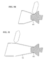
- the roller can thereafter move in the opposite direction, that is, from left to right as viewed in Figure 3G and flow form the material of land 10h into shoulder 164, as shown in Figure 3H .
- any further transitional changes can also be formed, such as the process step according to Figure 3I forming transition section 10i.
- the process according to Figures 3A-3I causes less distortion of the end edges, due to the movement of the roller 54 from right to left in the process step according to Figure 3B and therefore reduces the overall process time of the production of the tubular member from the configuration of Figure 3A to the configuration of Figure 3C .
- FIG. 4A another tubular member can be assembled, whereby an inner tubular member 200 can be positioned co-axially to tubular member 110 and held in place at one end by a baffle plate, such as 202.
- roller 54 can be moved inwardly and transversely of the tube 110, to form the end of tubular member 110 into a reduced diameter section 110b, and having a land section 110c, which conforms to the diameter of inner tubular member 200.
- the front shoulder 64 is undercut at 66, as will be described herein.
- mandrel 56 can be moved to the left as shown in Figure 4D , such that the first end portion 60 of mandrel 56 is positioned within the inner tubular member 200, with the inner tubular member 200 fitting within undercut section 66.
- the mandrel can also help define in this embodiment, the longitudinal position of the inner tube 200.
- the tube 200 is positioned within the baffle 202 in an interference fit.
- the end of the mandrel 60 is also insertable into the end of the tube 200 in an interference fit; but the force to insert the mandrel 56 into the inner tube 200 is less than the force to move the inner tube longitudinally within the baffle 200.
- the mandrel 56 is also designed to provide enough force to overcome the interference fit between the inner tube and the baffle 202, and thus the mandrel and tail stock are able to longitudinally position the inner tube 200 properly within the baffle 202. As shown in Figure 4C , inner tube 200 extends beyond baffle 202 by a distance x 1 , whereas when in the position of Figure 4D , the tube 200 has been pushed through the baffle 202 by the mandrel, so that it now extends through by a length of x 2 .
- transition section 110d With mandrel 56 as shown in Figure 4D , the roller 54 is urged into reduced diameter section 110b to create transition section 110d.
- the end 110c can then be flow formed as described above, from the position shown in Figure 4D to a position shown in Figure 4E , such that the end edges of section 110c abut shoulder 64. Due to undercut 66, inner tube 66 protrudes somewhat from the end of tube end 110c.
- the tube 110 can thereafter be finished by successive passes of the roller 54 to form the end transition profile 110e, as shown in Figure 4F . Also due to the uneven ends of the inner tube 200 and end 100c, the two ends can be easily welded together, to form the finished product.
- a further mandrel is shown at 256, generally comprised of a frusto-conical section 258 and a mandrel end section 260, where the mandrel end section 260 and frusto-conical section 258 are movable longitudinally relative to each other.
- Frusto-conical section 258 includes a front end section 264 forming a shoulder, an inclined section 266, which extends from a radial dimension at 268 to a radial dimension at 270.
- the frusto-conical section 258 further includes an inner bore at 272 for receiving the movable front end portion at 260, as described further herein.
- the mandrel end section 260 is comprised of a central movable pin member 280 comprised of a central rod 282 having a front head section 284, and an outer member 286.
- the outer member 286 includes a first diametrical section at 290 having a shoulder at 292 and a second diametrical portion at 294.
- the outer member 286 further includes an inner bore at 296 to receive pin section 282 therein.
- the pin portion 280 and outer member 286 are linked together by way of toggle links 298 and 299.
- the frusto-conical section 258 and mandrel end section 260 are movable longitudinally to a position where diametrical portion 294 ( Figure 5 ) is positioned within bore 272. It should be noted that in this position, shoulders 264 and 292 are longitudinally aligned; however, the mandrel can be designed so as to form an undercut section, similar to that described above in relation to undercut 66.
- the central pin portion 280 is movable longitudinally to the mandrel end portion 260 to a position where the outer profile of the toggle links are equal to or less than the profile defined by diameter portion 290.
- Section 286 includes an inner base at 274 forming an inner shoulder.
- Pin member 282 is also threaded at an end thereof to receive lock nuts 275, trapping a compression spring 276 therebetween. This spring loads the pin member 280 in the normally closed position of Figure 5 .
- Link 277 is pinned to member 286 and toggles between an end of pin member 282, and an end surface 278 of frusto-conical member.
- a catalytic converter 300 can be assembled with the use of mandrel 256 of Figures 5-7 , which includes outer tube 310, monolith substrates 312, and heat shields 314.
- the tube 310 can be held in place by chuck 50, with monoliths 312 positioned within tube 310.
- heat shield 314 is held in place on mandrel 256, where annular flange 316 of heat shield 314 is positioned on diameter portion 290 ( Figure 5 ) and abuts shoulder 292. With the center pin portion 280 retracted, toggle links 298 and 299 retain funnel-shaped section 318, as shown in Figure 8B .
- Mandrel 256 is integrated with tail stock member 400 ( Figure 8A ), which is movable on a top surface 402 of platen 404.
- tail stock member 400 is moved to the left, as shown in Figure 8B , to position the heat shield member 314 against the outer monolith substrate 312, as shown in Figure 8C .
- the spinning process can begin to produce a reduced diameter section 310a and land 310b.
- the mandrel can now be positioned in the configuration previously described with relation to Figure 6 to position shoulder 264 co-aligned with the end of heat shield annular flange 316.
- Roller 54 first forms transition section 310c, as shown in Figure 8D .
- tubular member 310b is now performed, as shown in Figure 8D , such that the length of the annular portion 310b is the identical length as annular flange 316 of heat shield 318 and forms a square abutment therewith.
- the roller 54 moves, and flow forms the material of section 310b, from the position of Figure 8D to the position of Figure 8E .
- the roller is thereafter moved towards the chuck, as shown in Figure 8F , to form a consistent transition section 310d.
- the end face 264 can overlap shoulder 292, to create an undercut, similar to 66 described above, such that the finished product has annular flange 316 protruding slightly beyond finished end 310b. This allows for easier welding of the two ends.
- any of the shoulders 20, 64, 164 or 264 can include the configuration to define the end edges.
- one of the shoulders could include a profile to define interdigitated raised portions, such as 400, such that the shoulder portions would include counterpart portions to define the recessed edges, for example at 402.
- the mandrel shoulders could include a recessed notch so as to define a nib, such as 410, as shown in Figures 11 and 12 .
- the mandrel shoulders could include a profile so as to define castellated portions 420.
- the mandrel shoulders could include recesses and dimples so as to define counterpart dimples 430 and recesses 432. As shown in Figures 17 and 18 , the shoulder could also include raised text 440 so as to define text 440 recessed into the end face of the finished work product.
- an alternate mandrel 356 is shown having a forward end section 358 and a forwardly facing shoulder 360. Intermediate the sections 358 and 360 are defined counterpart threaded sections 362 so as to define threaded section 450.
- the central pin portion 280 of the mandrel is moved to the configuration of Figure 7 , such that the toggle links collapse and the entire mandrel portion, including the outer portion 260 and the central pin portion 280, can be retracted by way of reversing the tail stock 400, which slides the entire mandrel out of the completed end.
- the partially completed catalytic converter 310 can now be reversed, with the completed end positioned within the chucks, and another heat shield can be positioned in the unfinished end of the catalytic converter 310, as just described.
Landscapes
- Engineering & Computer Science (AREA)
- Mechanical Engineering (AREA)
- Shaping Metal By Deep-Drawing, Or The Like (AREA)
- Manufacture, Treatment Of Glass Fibers (AREA)
- Spinning Methods And Devices For Manufacturing Artificial Fibers (AREA)
- Diaphragms For Electromechanical Transducers (AREA)
Abstract
Description
- The present invention relates a method and an apparatus for spinning a material to a circumferential configuration, according to the preamble of
claims 1 and 15 respectively. - It is well known in the art of spinning to provide a spinning machine including a plurality of chuck jaws, which confixedly hold material to be spun, such as a tubular member. The tubular member is spun in the chuck and a roller is moved transversely of the longitudinal length of the material, such that the roller engages the tube. The roller is then moved in an axis parallel to the longitudinal axis of the tubular member. In this way, the material of the tubular member can be formed into various configurations, such as a reduced diameter neck portion.
- For example, in
U.S. Patent 6,536,315 , a method of spinning a material to a circumferential configuration having a constant length is shown. The method comprises the steps of providing a tubular material to be spun; providing a tooling roller and moving it tangentially towards the material; causing relative rotational movement between the roller and the material; and moving the roller along an axis parallel to the longitudinal axis, thereby spinning the material to a radially different configuration. - As efficient as the spinning process is, one of the difficulties is controlling the length of the end edges of the tubular member while spinning and the overall length after spun. Any discontinuity in the length of the end edges is exaggerated, such that after spinning, the end edges of the material spun could be rather jagged even including sinuous-shaped contours. This discontinuity of the end edges has heretofore required secondary operations to provide a constant length end. Not only is the discontinuity of the end edges a disadvantage, but the secondary operation more than likely requires removal of the tubular member from the chuck jaws, thereby losing any longitudinal registration with the tooling.
- The objects of the invention have been accomplished by providing a method of spinning a material to a circumferential configuration having a constant length, according to
claim 1. - Patent Abstracts of Japan publication number
JP 02 070327 A - Patent Abstract of Japan Patent publication number
JP 06 182471 A -
DE 503 592 discloses a method of making insert dishes for centrifuges. The insert dishes consist of a thin conical shell with thicker flanges connected thereto and are made of sheet metal. The method disclosed involves displacing the sheet metal material resulting in a reduced material thickness by pressing a rolling wheel onto a portion of the material against a die. The material takes the shape of the outer surface of the die during this spinning process. Upon completion of the spinning process, the end of the material has a thickness greater than the remainder of the material. - In one preferred embodiment the shoulder is provided as a transverse plane, transverse to the longitudinal axis. The shoulder can be provided in the form of a mandrel. The mandrel can be provided in a dimension generally along the longitudinal axis, having a first end portion with a constant first end diameter to extend below the free end edges, and a second diameter, spaced from the first end diameter, and having a diameter larger than the first end diameter forming the shoulder therebetween. The material can be provided tubular in shape. The material can be held by a chuck, where the chuck spins about the longitudinal axis to spin the tubular material. The tooling roller is moved in a direction from the chuck towards the mandrel. The free end edges are spun to a diameter less than the first end diameter, and the first end of the mandrel is forced into the tubular spun end.
- In another preferred embodiment, an inner member is provided, profiled for receipt within the tubular member, wherein the tubular member is spun to encapsulate the inner member. In this manner a catalytic converter is formed by the further steps of inserting at least one monolith substrate into the tubular member, prior to the spinning process, and spacing the monolith from an end to be spun; positioning a funnel shaped heat shield into the tubular member, with a reduced diameter section directed outwardly, and with an enlarged diameter section adjacent to the substrate; and spinning the tubular end to generally conform to the shape of the funnel shaped heat shield.
- The mandrel can be provided with a frusto-conical shaped portion, extending continuously from the second diameter. The second diameter is less than a diameter of the tubular member, and the frusto-conical shaped portion has an end diameter larger than a diameter of the tubular member. The mandrel, prior to the spinning step, is positioned with the frusto-conical shaped portion in abutment with the tubular member, and the tubular member is spun by moving the tooling roller in a direction from the mandrel towards the chuck, thereby collapsing the tubular member against the frusto-conical shaped member. The mandrel is thereafter gradually backed out, and the material is continuously spun to a further reduced diameter portion.
- In another aspect of the invention, an apparatus for spinning a material workpiece to a circumferential configuration having a constant length with the features of claim 15 is provided.
- The mandrel can further comprise a frusto-conical portion extending from the mandrel first end, the frusto-conical portion enlarging away from the mandrel first end, whereby an end of the frusto-conical portion forms the shoulder. The frusto-conical portion may be longitudinally movable relative to the mandrel first end. The mandrel first end may have a holding mechanism for holding an item to be inserted into the material workpiece. The holding mechanism may be comprised of telescopically movable members, connected at their front ends by way of a toggle link, whereby the members have a first position wherein the toggle links form the holding member and have a radial dimension greater than the mandrel first end, and a second position whereby the toggle links have a radial dimension equal to or less than the mandrel first end.
-
Figures 1A-1F show diagrammatically a spinning process including the provision of a mandrel to form the spun end with a constant longitudinal length; -
Figures 2A-2F show an apparatus and process steps substantially according to the process shown inFigures 1A-1F ; -
Figures 3A-3I show a further embodiment of the apparatus and the associated process steps; -
Figures 4A-4G show yet another embodiment of the apparatus and the associated process steps; -
Figures 5-7 show an alternate embodiment of a mandrel; -
Figures 8A-8F show the apparatus and process steps incorporating the mandrel ofFigures 5-7 ; and -
Figures 9-20 show various end edges which can be created with the disclosed method and apparatus. - With reference first to
Figures 1A-1F , the length control process will be described diagrammatically. It should be understood that in each of theFigures 1A-1F , the dashed line is the longitudinal center line, with only one-half of the tubular member being shown. - With reference first to
Figure 1A , a tubular member such as 10 is shown, which would be held in a spinning machine, as hereafter described and spun about alongitudinal axis 12. A roller such as 14 is movable transversely of thelongitudinal axis 12, as well as along any other longitudinal axis, which is parallel toaxis 12. As shown inFigure 1B ,roller 14, as it moves transversely and laterally, moves and formstubular member 10 to have a radiused portion 10A. As shown inFigure 1C , a mandrel is shown at 16 having afirst end 18 of a constant diameter. A shoulder is formed at 20 as will be described. With respect still toFigure 1C , as described above, as thetubular member 10 is spun, a jagged or discontinuous end edge is formed, and is shown at 22 inFigure 1C . - As shown in
Figure 1D ,mandrel 16 is shown withfirst end 18 extending into the tubular member, withshoulder 20 positioned adjacent to jaggededge 22. As shown in phantom inFigure 1D , the roller continues to process the contour of thetubular member 10 to the desired shape. As shown inFigure 1E , once the tubular member is near its end configuration,roller 14 may now continue to move from left to right as viewed inFigure 1E by pressing the material intermediate theroller 14 and the mandrelfirst end 18. This pressure, and the entrapment between themandrel 18, causes a flow forming of the material, such that the material bulges or is formed into a wave as shown inFigure 1E as 24. This causes an elongation of the material, such that the material flow forms until it abutsshoulder 20, as shown in the final position 1F, whereby the material is flow formed into a constant shoulder, thereby providing a constant thickness end and length to the material andtubular member 10. - Advantageously, the
mandrel 16 and the mechanism for holding and spinning the material can be provided in the same apparatus, therefore, the longitudinal registration between the two is correlated, such that the longitudinal length of the end device can be fixed in one apparatus. - With respect now to
Figure 2A , an apparatus is shown at 50 and is generally comprised of a spinning chuck at 52, aroller mechanism 54, and a mandrel portion at 56. It should be understood that themandrel 56 forms the length-controlled tooling, which is attached to the primary axis tail stock of the spinning machine. As shown inFigure 2A , the spinningchuck 52 is generally comprised of a plurality of chuck jaws, such as 58, which are movable radially inward and outward so as to retaintubular member 10 therein. As shown inFigure 2B ,mandrel 56 is comprised of afirst end portion 60 having a diameter d1 and a lead-in section at 62. Thefirst end portion 60 has a constant diameter which extends rearwardly to a shoulder section at 64. - With the apparatus as described in
Figures 2A and2B , the process will be described with respect toFigures 2C to 2F . As shown first inFigure 2C ,roller 54 is movable in a transverse direction towardtubular member 10, such that atapered section 10a is formed intubular member 10.Mandrel 56 is now movable towardtubular member 10 to the position shown inFigure 2C , where thefirst end 60 ofmandrel 56 is positioned within the taperedsection 10a oftubular member 10. As shown inFigure 2C , tube end orland 10b is substantially parallel withfirst end 60 ofmandrel 56 and is supported by the mandrel first end. As shown inFigure 2D , theroller 54 is now projected into thetubular member 10, to create atransition section 10c, and causing an enlargement or elongation ofland area 10b. As shown inFigures 2D and 2E , as the roller continues to spinland 10b, from the position shown inFigure 2D to the position shown inFigure 2E , the spinning flow forms the material ofland 10b into shoulder 64 (Figure 2B ), as best shown inFigure 2E . If necessary, theroller 56 can be moved in an opposite sense as shown, to smooth out thetransition sections Figure 2F to form a modifiedtransition section 10d. As mentioned above, aschuck 52 andmandrel 56 are incorporated into the same spinning apparatus, the longitudinal registration betweenchuck 52 andmandrel 56 can be monitored and held in registration, such that the length oftube 10 can be controlled. - With reference now to
Figures 3A and3B , an alternate mandrel is shown at 156 having a first end at 160, with a tapered end portion at 162. A fiusto-conical section 166 is positioned rearwardly offirst end 160, such that a front end of the frusto-conical portion 166forms shoulder 164. The frusto-conical portion 166 further comprises aconical surface 168, having a first diameter or radial portion at 170 and a second and enlarged diameter or radial portion at 172. In the embodiment shown inFigure 3B , theradial portion 172 is slightly smaller than the diameter oftubular member 10.Mandrel 156 is moved towardstubular member 10, such thatconical surface 168 is positioned within an end of thetubular member 10.Roller 54 is now moved towardstubular member 10 and is moved in a direction inwardly and towards thechuck 52, as shown inFigure 3C , such that aportion 10c of the tube is pressed against, and conforms to, theconical surface 168. This also forms another reduced diameter section at 10d integral with the remainder oftubular member 10. - With respect now to
Figures 3D and 3E ,roller 54 now takes deep passes, first from right to left as inFigure 3D , to definetransition section 10e, and then from left to right as shown inFigure 3E , to define a near complete configuration of the transition section as 10f. When in the position ofFigure 3E , themandrel 156 is moved to the right, to the position shown inFigure 3F , and atransition section 10g is formed, together withland 10h, which lies adjacent tomandrel portion 160. When in this position, the roller can thereafter move in the opposite direction, that is, from left to right as viewed inFigure 3G and flow form the material ofland 10h intoshoulder 164, as shown inFigure 3H . Any further transitional changes can also be formed, such as the process step according toFigure 3I formingtransition section 10i. Advantageously, the process according toFigures 3A-3I causes less distortion of the end edges, due to the movement of theroller 54 from right to left in the process step according toFigure 3B and therefore reduces the overall process time of the production of the tubular member from the configuration ofFigure 3A to the configuration ofFigure 3C . - With reference now to
Figure 4A , another tubular member can be assembled, whereby an innertubular member 200 can be positioned co-axially totubular member 110 and held in place at one end by a baffle plate, such as 202. As shown inFigures 4B and 4C ,roller 54 can be moved inwardly and transversely of thetube 110, to form the end oftubular member 110 into a reduceddiameter section 110b, and having aland section 110c, which conforms to the diameter of innertubular member 200. As shown best inFigure 4G , thefront shoulder 64 is undercut at 66, as will be described herein. When thetube 110 andinner tube 200 are in the position shown inFigure 4C ,mandrel 56 can be moved to the left as shown inFigure 4D , such that thefirst end portion 60 ofmandrel 56 is positioned within the innertubular member 200, with the innertubular member 200 fitting within undercutsection 66. The mandrel can also help define in this embodiment, the longitudinal position of theinner tube 200. Thetube 200 is positioned within thebaffle 202 in an interference fit. The end of themandrel 60 is also insertable into the end of thetube 200 in an interference fit; but the force to insert themandrel 56 into theinner tube 200 is less than the force to move the inner tube longitudinally within thebaffle 200. Themandrel 56 is also designed to provide enough force to overcome the interference fit between the inner tube and thebaffle 202, and thus the mandrel and tail stock are able to longitudinally position theinner tube 200 properly within thebaffle 202. As shown inFigure 4C ,inner tube 200 extends beyondbaffle 202 by a distance x1, whereas when in the position ofFigure 4D , thetube 200 has been pushed through thebaffle 202 by the mandrel, so that it now extends through by a length of x2. - With
mandrel 56 as shown inFigure 4D , theroller 54 is urged into reduceddiameter section 110b to createtransition section 110d. Theend 110c can then be flow formed as described above, from the position shown inFigure 4D to a position shown inFigure 4E , such that the end edges ofsection 110c abut shoulder 64. Due to undercut 66,inner tube 66 protrudes somewhat from the end oftube end 110c. Thetube 110 can thereafter be finished by successive passes of theroller 54 to form theend transition profile 110e, as shown inFigure 4F . Also due to the uneven ends of theinner tube 200 and end 100c, the two ends can be easily welded together, to form the finished product. - With respect now to
Figures 5-7 , a further mandrel is shown at 256, generally comprised of a frusto-conical section 258 and amandrel end section 260, where themandrel end section 260 and frusto-conical section 258 are movable longitudinally relative to each other. Frusto-conical section 258 includes afront end section 264 forming a shoulder, aninclined section 266, which extends from a radial dimension at 268 to a radial dimension at 270. The frusto-conical section 258 further includes an inner bore at 272 for receiving the movable front end portion at 260, as described further herein. - With respect still to
Figure 5 , themandrel end section 260 is comprised of a centralmovable pin member 280 comprised of acentral rod 282 having afront head section 284, and anouter member 286. Theouter member 286 includes a first diametrical section at 290 having a shoulder at 292 and a second diametrical portion at 294. Theouter member 286 further includes an inner bore at 296 to receivepin section 282 therein. As shown, thepin portion 280 andouter member 286 are linked together by way oftoggle links Figure 6 , the frusto-conical section 258 andmandrel end section 260 are movable longitudinally to a position where diametrical portion 294 (Figure 5 ) is positioned withinbore 272. It should be noted that in this position, shoulders 264 and 292 are longitudinally aligned; however, the mandrel can be designed so as to form an undercut section, similar to that described above in relation to undercut 66. - Finally, as shown in
Figure 7 , thecentral pin portion 280 is movable longitudinally to themandrel end portion 260 to a position where the outer profile of the toggle links are equal to or less than the profile defined bydiameter portion 290.Section 286 includes an inner base at 274 forming an inner shoulder.Pin member 282 is also threaded at an end thereof to receivelock nuts 275, trapping acompression spring 276 therebetween. This spring loads thepin member 280 in the normally closed position ofFigure 5 .Link 277 is pinned tomember 286 and toggles between an end ofpin member 282, and anend surface 278 of frusto-conical member. Thus, when frusto-conical member 258 retracts to the position shown inFigure 7 ,pin member 282 is pushed outwardly of themember 286, thereby lowering the toggle links 298, 299. - With respect now to
Figures 8A-8F , acatalytic converter 300 can be assembled with the use ofmandrel 256 ofFigures 5-7 , which includes outer tube 310,monolith substrates 312, andheat shields 314. As shown inFigure 8A , the tube 310 can be held in place bychuck 50, withmonoliths 312 positioned within tube 310. As shown best inFigure 8B ,heat shield 314 is held in place onmandrel 256, whereannular flange 316 ofheat shield 314 is positioned on diameter portion 290 (Figure 5 ) and abutsshoulder 292. With thecenter pin portion 280 retracted,toggle links section 318, as shown inFigure 8B .Mandrel 256 is integrated with tail stock member 400 (Figure 8A ), which is movable on atop surface 402 ofplaten 404. - Thus, to position the
heat shield 314 within tube member 310,tail stock member 400 is moved to the left, as shown inFigure 8B , to position theheat shield member 314 against theouter monolith substrate 312, as shown inFigure 8C . With the heat shield positioned therein as shown, the spinning process can begin to produce a reduceddiameter section 310a andland 310b. The mandrel can now be positioned in the configuration previously described with relation toFigure 6 to positionshoulder 264 co-aligned with the end of heat shieldannular flange 316.Roller 54 firstforms transition section 310c, as shown inFigure 8D . The flow forming oftubular member 310b is now performed, as shown inFigure 8D , such that the length of theannular portion 310b is the identical length asannular flange 316 ofheat shield 318 and forms a square abutment therewith. Theroller 54 moves, and flow forms the material ofsection 310b, from the position ofFigure 8D to the position ofFigure 8E . The roller is thereafter moved towards the chuck, as shown inFigure 8F , to form aconsistent transition section 310d. As mentioned above, theend face 264 can overlapshoulder 292, to create an undercut, similar to 66 described above, such that the finished product hasannular flange 316 protruding slightly beyondfinished end 310b. This allows for easier welding of the two ends. - With respect now to
Figures 9-20 , various end edges can be created by the disclosed method and apparatus, whereby any of theshoulders Figures 9 and 10 , one of the shoulders could include a profile to define interdigitated raised portions, such as 400, such that the shoulder portions would include counterpart portions to define the recessed edges, for example at 402. Similarly, the mandrel shoulders could include a recessed notch so as to define a nib, such as 410, as shown inFigures 11 and 12 . As shown inFigures 13 and 14 , the mandrel shoulders could include a profile so as to definecastellated portions 420. Also with respect toFigures 15 and 16 , the mandrel shoulders could include recesses and dimples so as to definecounterpart dimples 430 and recesses 432. As shown inFigures 17 and 18 , the shoulder could also include raisedtext 440 so as to definetext 440 recessed into the end face of the finished work product. - With respect now to
Figures 19 and 20 , analternate mandrel 356 is shown having aforward end section 358 and a forwardly facingshoulder 360. Intermediate thesections sections 362 so as to define threadedsection 450. - As should be appreciated, once the spinning process is complete, to the configuration of
Figure 8F , thecentral pin portion 280 of the mandrel is moved to the configuration ofFigure 7 , such that the toggle links collapse and the entire mandrel portion, including theouter portion 260 and thecentral pin portion 280, can be retracted by way of reversing thetail stock 400, which slides the entire mandrel out of the completed end. The partially completed catalytic converter 310 can now be reversed, with the completed end positioned within the chucks, and another heat shield can be positioned in the unfinished end of the catalytic converter 310, as just described.
Claims (20)
- A method of spinning a material to a circumferential configuration having a constant length, the method comprising the steps of:providing the material (10) to be spun;providing a tooling roller (14, 54) and moving it tangentially towards said material;causing relative rotational movement between said roller and said material; andmoving said roller along an axis parallel to said longitudinal axis (12), thereby spinning said material to a radially different configuration; characterized by the steps of:providing a shoulder (20) with a predefined definition, andmoving said tooling roller towards said shoulder, thereby flow forming said material towards and into said shoulder (20) such that free end edges (22) of said material is forced into and abut said shoulder (20) to conform said end edges to said predefined definition.
- The method of claim 1, characterized in that said shoulder is provided as a transverse plane, transverse to said longitudinal axis.
- The method of either of claims 1 or 2, characterized in that said shoulder is provided in the form of a mandrel (16).
- The method of any of claims 1-3, characterized in that said mandrel is provided in a dimension generally along said longitudinal axis, having a first end portion (18) with a constant first end diameter to extend below said free end edges, and a second diameter, spaced from said first end diameter, and having a diameter larger than said first end diameter forming said shoulder therebetween.
- The method of any of claims 1-4, characterized in that said material is provided tubular in shape.
- The method of any of claims 1-5, characterized in that said material is held by a chuck (52), and said chuck spins about said longitudinal axis to spin said tubular material.
- The method of any of claims 1-6, characterized in that said tooling roller is moved in a direction from said chuck towards said mandrel.
- The method of any of claims 1-7, characterized in that said free end edges are spun to a diameter less than said first end diameter, and said first end of said mandrel is forced into said tubular spun end.
- The method of any of claims 1-8, further characterized by the step of providing an inner member (200, 314), profiled for receipt within said tubular member, characterized in that said tubular member is spun to encapsulate said inner member.
- The method of claim 9, characterized in that a catalytic converter is formed by the further steps of:inserting at least one monolith substrate (312) into said tubular member, prior to said spinning process, and spacing said monolith from an end to be spun;positioning a funnel shaped heat shield (314) into said tubular member, with a reduced diameter section directed outwardly, and with an enlarged diameter section adjacent to said substrate; andspinning said tubular end (310a) to generally conform to the shape of said funnel shaped heat shield.
- The method of any of claims 1-10, characterized in that said mandrel is provided with a frusto-conical shaped portion (166, 258), extending continuously from said first end portion.
- The method of claim 11, characterized in that said second diameter is less than a diameter of said tubular member, and said frusto-conical shaped portion has an end diameter larger than a diameter of said tubular member.
- The method of claim 12, characterized in that said mandrel, prior to said spinning step, is positioned with said frusto-conical shaped portion in abutment with said tubular member, and said tubular member is spun by moving said tooling roller in a direction from said mandrel towards said chuck, thereby collapsing said tubular member against said frusto-conical shaped member.
- The method of claim 13, further comprising the steps of gradually backing the mandrel out, and continuously spinning the material to a further reduced diameter portion.
- A spinning apparatus for spinning a material workpiece to a circumferential configuration having a constant length, the spinning apparatus comprising:a spinning chuck (52) having jaws (58) to hold a material workpiece to be spun;
anda mandrel (56) having a first end having a constant diameter, which terminates into a shoulder (20), the mandrel being longitudinally movable into an open end of the workpiece, and a spinning roller (14,54), characterized in that said a spinning roller (14, 54), in operation, moves towards said shoulder (20) to flow form an end of the material workpiece into said shoulder so that an edge of the material workpiece is forced into and contacts said shoulder (20) - The spinning apparatus of claim 15, characterized in that said mandrel further comprises a frusto-conical portion (166, 258) extending from said mandrel first end, said frusto-conical portion enlarging away from said mandrel first end, whereby an end of said frusto-conical portion forms said shoulder.
- The spinning apparatus according to either of claims 15 or 16, characterized in that said frusto-conical portion is longitudinally movable relative to said mandrel first end.
- The spinning apparatus of claim according to any of claims 15-17, characterized in that said mandrel first end has a holding mechanism (260) for holding an item to be inserted into said material workpiece.
- The spinning apparatus of claim 18, characterized in that said holding mechanism is comprised of telescopically movable members (280, 286), connected at their front ends by way of a toggle link (298, 299), whereby the members have a first position characterized in that the toggle links form the holding member and have a radial dimension greater than the mandrel first end, and a second position whereby the toggle links have a radial dimension equal to or less than the mandrel first end.
- The spinning apparatus of any of claims 15-19, further characterized in that the shoulder (20) is provided with a predefined definition (400, 402; 410; 420, 430, 432; 440; or 450).
Applications Claiming Priority (3)
| Application Number | Priority Date | Filing Date | Title |
|---|---|---|---|
| US300347 | 2002-11-20 | ||
| US10/300,347 US6983632B2 (en) | 2002-11-20 | 2002-11-20 | Method and apparatus for spinning to a constant length |
| PCT/US2003/036534 WO2004045786A1 (en) | 2002-11-20 | 2003-11-14 | Method and apparatus for spinning to a constant lenght |
Publications (2)
| Publication Number | Publication Date |
|---|---|
| EP1565282A1 EP1565282A1 (en) | 2005-08-24 |
| EP1565282B1 true EP1565282B1 (en) | 2011-03-02 |
Family
ID=32297898
Family Applications (1)
| Application Number | Title | Priority Date | Filing Date |
|---|---|---|---|
| EP03781956A Expired - Lifetime EP1565282B1 (en) | 2002-11-20 | 2003-11-14 | Method and apparatus for spinning to a constant lenght |
Country Status (11)
| Country | Link |
|---|---|
| US (1) | US6983632B2 (en) |
| EP (1) | EP1565282B1 (en) |
| JP (1) | JP4902118B2 (en) |
| CN (1) | CN100374224C (en) |
| AT (1) | ATE500007T1 (en) |
| AU (1) | AU2003287655A1 (en) |
| CA (1) | CA2506675C (en) |
| DE (1) | DE60336256D1 (en) |
| ES (1) | ES2380468T3 (en) |
| HK (1) | HK1077776B (en) |
| WO (1) | WO2004045786A1 (en) |
Families Citing this family (12)
| Publication number | Priority date | Publication date | Assignee | Title |
|---|---|---|---|---|
| NL1020171C2 (en) * | 2002-03-13 | 2003-09-16 | Johan Massee | Method and forming machine for machining a workpiece. |
| JP4729322B2 (en) * | 2005-03-31 | 2011-07-20 | カヤバ工業株式会社 | Press molding method and press molding apparatus |
| US20080274242A1 (en) * | 2006-07-21 | 2008-11-06 | Ecolab Inc. | Antimicrobial compositions and methods for treating packaged food products |
| US8117878B1 (en) * | 2007-08-17 | 2012-02-21 | Novellus System, Inc. | Method and apparatus for forming and texturing process shields |
| US7819040B2 (en) * | 2007-11-28 | 2010-10-26 | Transform Automotive Llc | Method for making vehicle axle differential casing and resultant product |
| US8572846B2 (en) * | 2008-11-05 | 2013-11-05 | Faurecia Emissions Control Technologies LLC | Hoop-stress controlled shrinking for exhaust component |
| CN101693271B (en) * | 2009-10-12 | 2013-04-24 | 彭永锋 | Flat plate revolving press and manufacture method of similar workpiece of fan impeller front plate |
| US8444522B2 (en) | 2010-04-27 | 2013-05-21 | Metal Forming & Coining Corporation | Flow-formed differential case assembly |
| US8628444B2 (en) | 2010-07-01 | 2014-01-14 | Metal Forming & Coining Corporation | Flow-formed differential case assembly |
| CN102145358B (en) * | 2010-11-30 | 2012-12-26 | 黄幼华 | Circular upper cap spinning device of electric dust remover insulator chamber |
| CN104148900A (en) * | 2014-08-13 | 2014-11-19 | 权明勇 | Machining technology for annular steel belts |
| JP2019130577A (en) * | 2018-02-01 | 2019-08-08 | 株式会社Ihiエアロスペース | Rolled member manufacturing method and rolled member manufacturing apparatus |
Family Cites Families (28)
| Publication number | Priority date | Publication date | Assignee | Title |
|---|---|---|---|---|
| DE503592C (en) | 1928-11-04 | 1930-07-25 | Bergedorfer Eisenwerk Akt Ges | Process for the production of insert plates intended for centrifuges |
| JPS5639136A (en) * | 1979-09-04 | 1981-04-14 | Kanemitsu Doukou Yousetsushiyo:Goushi | Manufacture of multigrooved v-pulley |
| JPH0270327A (en) | 1988-09-01 | 1990-03-09 | Sumitomo Light Metal Ind Ltd | Spinning of pipe material |
| JPH0811264B2 (en) * | 1991-05-17 | 1996-02-07 | 株式会社ゴーシュー | Internal gear forming method |
| DE59301383D1 (en) * | 1992-05-07 | 1996-02-22 | Wf Maschinenbau Blechformtech | Method for manufacturing a gear part |
| JP3390838B2 (en) | 1992-12-18 | 2003-03-31 | 株式会社アローエンタープライズ | Method of forming automotive wheels |
| NL9400927A (en) * | 1994-06-08 | 1996-01-02 | Johan Massee | Method and device for forming an edge on a lamp reflector. |
| DE19517671C2 (en) * | 1995-05-13 | 2000-07-13 | Krupp Kunststofftechnik Gmbh | Device for the formation of a tapered and flanged section on a cylindrical hollow body |
| NL1000851C2 (en) * | 1995-07-20 | 1997-01-21 | Massee Johan | Method and device for forcing a metal sheet. |
| DE19532951A1 (en) * | 1995-09-07 | 1997-03-13 | Dynamit Nobel Ag | Method and device for the production of pressure-rolled pipes with internal wall thickening at the ends |
| NL1001675C2 (en) * | 1995-11-17 | 1997-05-21 | Johan Massee | Method and device for making a product by forcing. |
| DE19545890C2 (en) * | 1995-12-08 | 1998-12-17 | Leifeld Gmbh & Co | Process for the production of a workpiece with a hub and a pressure or pressure rolling machine |
| US5687599A (en) * | 1996-01-04 | 1997-11-18 | Reynolds Metals Company | Method of forming a can with an electromagnetically formed contoured sidewall and necked end |
| NL1003403C2 (en) * | 1996-06-24 | 1998-01-07 | Johan Massee | Device for machining a workpiece. |
| JP3567629B2 (en) * | 1996-07-25 | 2004-09-22 | マツダ株式会社 | Method and apparatus for forming annular body having internal teeth |
| CN1198691A (en) * | 1996-08-05 | 1998-11-11 | 株式会社金光 | Method of molding cylindrical portion of central bore-carrying sheet metal |
| US5937516A (en) * | 1996-12-13 | 1999-08-17 | General Motors Corporation | Method for spin forming articles |
| NL1005319C2 (en) * | 1997-02-20 | 1998-08-24 | Johan Massee | Device for machining a workpiece. |
| NL1005318C2 (en) * | 1997-02-20 | 1998-08-24 | Johan Massee | Device for machining a workpiece, as well as methods for use with such a device. |
| JP2957176B1 (en) * | 1998-09-24 | 1999-10-04 | 株式会社三五 | Manufacturing method of double structure container |
| JP3308503B2 (en) * | 1999-01-26 | 2002-07-29 | 株式会社三五 | Manufacturing method of intermediate restriction pipe |
| JP2000263161A (en) * | 1999-03-12 | 2000-09-26 | Toyota Motor Corp | Spinning apparatus and spinning method |
| JP2000265830A (en) * | 1999-03-16 | 2000-09-26 | Toyota Motor Corp | Monolithic catalytic converter and method of manufacturing the same |
| US6381843B1 (en) * | 1999-08-03 | 2002-05-07 | Sango Co., Ltd. | Method of producing a catalytic converter |
| DE10005578C2 (en) * | 2000-02-09 | 2001-09-13 | Leico Werkzeugmaschb Gmbh & Co | Method and pressure rolling device for producing a hollow body |
| JP2001303943A (en) * | 2000-04-24 | 2001-10-31 | Sakamoto Industry Co Ltd | Catalytic converter for internal combustion engine |
| CA2421898A1 (en) * | 2000-09-01 | 2002-03-14 | The Gates Corporation | Method of spinning a pulley from a tubular blank |
| US6505490B2 (en) * | 2001-02-28 | 2003-01-14 | The Gates Corporation | Method of forming a sheet metal cup without a mandrel |
-
2002
- 2002-11-20 US US10/300,347 patent/US6983632B2/en not_active Expired - Lifetime
-
2003
- 2003-11-14 DE DE60336256T patent/DE60336256D1/en not_active Expired - Lifetime
- 2003-11-14 HK HK05112113.2A patent/HK1077776B/en not_active IP Right Cessation
- 2003-11-14 JP JP2004553736A patent/JP4902118B2/en not_active Expired - Fee Related
- 2003-11-14 AT AT03781956T patent/ATE500007T1/en not_active IP Right Cessation
- 2003-11-14 EP EP03781956A patent/EP1565282B1/en not_active Expired - Lifetime
- 2003-11-14 WO PCT/US2003/036534 patent/WO2004045786A1/en not_active Ceased
- 2003-11-14 ES ES03781956T patent/ES2380468T3/en not_active Expired - Lifetime
- 2003-11-14 CA CA2506675A patent/CA2506675C/en not_active Expired - Fee Related
- 2003-11-14 CN CNB2003801036922A patent/CN100374224C/en not_active Expired - Fee Related
- 2003-11-14 AU AU2003287655A patent/AU2003287655A1/en not_active Abandoned
Also Published As
| Publication number | Publication date |
|---|---|
| JP4902118B2 (en) | 2012-03-21 |
| JP2006506233A (en) | 2006-02-23 |
| EP1565282A1 (en) | 2005-08-24 |
| AU2003287655A1 (en) | 2004-06-15 |
| DE60336256D1 (en) | 2011-04-14 |
| CN100374224C (en) | 2008-03-12 |
| US20040093922A1 (en) | 2004-05-20 |
| HK1077776A1 (en) | 2006-02-24 |
| HK1077776B (en) | 2011-07-08 |
| ATE500007T1 (en) | 2011-03-15 |
| US6983632B2 (en) | 2006-01-10 |
| WO2004045786A1 (en) | 2004-06-03 |
| ES2380468T3 (en) | 2012-05-11 |
| CA2506675A1 (en) | 2004-06-03 |
| CN1744957A (en) | 2006-03-08 |
| CA2506675C (en) | 2011-09-13 |
Similar Documents
| Publication | Publication Date | Title |
|---|---|---|
| US4055976A (en) | Method of roller spinning cup-shaped metal blanks and roller construction therefor | |
| EP1565282B1 (en) | Method and apparatus for spinning to a constant lenght | |
| US4192167A (en) | Process and apparatus for upsetting pipe ends | |
| CN111889967B (en) | Flat plate winding type rim forming process | |
| US6105410A (en) | Method for forming a hub disk and metal spinning roller for use in the forming of a hub disk | |
| US5806358A (en) | Method and apparatus for the manufacture of a workpiece having a boss | |
| KR20090122889A (en) | Workpiece manufacturing method | |
| JPS60500283A (en) | Method and device for forming a constriction in a hollow body | |
| CN108463296B (en) | Spinning device and spinning method | |
| US6757976B2 (en) | Method for manufacturing alloy wheel for automobile | |
| JP2001212626A (en) | Flow forming method and forming machine | |
| US20030019269A1 (en) | Method and a press cylinder device for producing a hollow body | |
| US4470281A (en) | Method of forming end face wall having concentric recess in tubular workpiece | |
| US5732586A (en) | Cold extrusion for helical gear teeth | |
| JPS6357020U (en) | ||
| US4208900A (en) | Axle spindle forming apparatus | |
| US20080250838A1 (en) | Method and device for producing metal rings | |
| US4100781A (en) | Axle spindle forming method | |
| US6298702B1 (en) | Method for making seamless wheel rims | |
| US4068362A (en) | Method of forming rings | |
| US4205545A (en) | Method of forming louvered openings in tubular members | |
| KR960002909B1 (en) | Method of making pulleys with v-shaped grooves | |
| JP2001129631A (en) | Method of manufacturing shaft with large diameter flange | |
| CA1084782A (en) | Method of forming rings | |
| JPS5913936B2 (en) | A method for manufacturing a crank arm for a welded crankshaft and a press device for carrying out this method |
Legal Events
| Date | Code | Title | Description |
|---|---|---|---|
| PUAI | Public reference made under article 153(3) epc to a published international application that has entered the european phase |
Free format text: ORIGINAL CODE: 0009012 |
|
| 17P | Request for examination filed |
Effective date: 20050616 |
|
| AK | Designated contracting states |
Kind code of ref document: A1 Designated state(s): AT BE BG CH CY CZ DE DK EE ES FI FR GB GR HU IE IT LI LU MC NL PT RO SE SI SK TR |
|
| AX | Request for extension of the european patent |
Extension state: AL LT LV MK |
|
| REG | Reference to a national code |
Ref country code: HK Ref legal event code: DE Ref document number: 1077776 Country of ref document: HK |
|
| DAX | Request for extension of the european patent (deleted) | ||
| 17Q | First examination report despatched |
Effective date: 20061113 |
|
| GRAP | Despatch of communication of intention to grant a patent |
Free format text: ORIGINAL CODE: EPIDOSNIGR1 |
|
| GRAS | Grant fee paid |
Free format text: ORIGINAL CODE: EPIDOSNIGR3 |
|
| GRAA | (expected) grant |
Free format text: ORIGINAL CODE: 0009210 |
|
| AK | Designated contracting states |
Kind code of ref document: B1 Designated state(s): AT BE BG CH CY CZ DE DK EE ES FI FR GB GR HU IE IT LI LU MC NL PT RO SE SI SK TR |
|
| REG | Reference to a national code |
Ref country code: GB Ref legal event code: FG4D |
|
| REG | Reference to a national code |
Ref country code: CH Ref legal event code: EP |
|
| REG | Reference to a national code |
Ref country code: IE Ref legal event code: FG4D |
|
| REF | Corresponds to: |
Ref document number: 60336256 Country of ref document: DE Date of ref document: 20110414 Kind code of ref document: P |
|
| REG | Reference to a national code |
Ref country code: DE Ref legal event code: R096 Ref document number: 60336256 Country of ref document: DE Effective date: 20110414 |
|
| REG | Reference to a national code |
Ref country code: RO Ref legal event code: EPE |
|
| REG | Reference to a national code |
Ref country code: NL Ref legal event code: T3 |
|
| REG | Reference to a national code |
Ref country code: CH Ref legal event code: NV Representative=s name: BUECHEL, VON REVY & PARTNER |
|
| REG | Reference to a national code |
Ref country code: HK Ref legal event code: GR Ref document number: 1077776 Country of ref document: HK |
|
| PG25 | Lapsed in a contracting state [announced via postgrant information from national office to epo] |
Ref country code: SE Free format text: LAPSE BECAUSE OF FAILURE TO SUBMIT A TRANSLATION OF THE DESCRIPTION OR TO PAY THE FEE WITHIN THE PRESCRIBED TIME-LIMIT Effective date: 20110302 Ref country code: GR Free format text: LAPSE BECAUSE OF FAILURE TO SUBMIT A TRANSLATION OF THE DESCRIPTION OR TO PAY THE FEE WITHIN THE PRESCRIBED TIME-LIMIT Effective date: 20110603 |
|
| PG25 | Lapsed in a contracting state [announced via postgrant information from national office to epo] |
Ref country code: SI Free format text: LAPSE BECAUSE OF FAILURE TO SUBMIT A TRANSLATION OF THE DESCRIPTION OR TO PAY THE FEE WITHIN THE PRESCRIBED TIME-LIMIT Effective date: 20110302 Ref country code: AT Free format text: LAPSE BECAUSE OF FAILURE TO SUBMIT A TRANSLATION OF THE DESCRIPTION OR TO PAY THE FEE WITHIN THE PRESCRIBED TIME-LIMIT Effective date: 20110302 Ref country code: CY Free format text: LAPSE BECAUSE OF FAILURE TO SUBMIT A TRANSLATION OF THE DESCRIPTION OR TO PAY THE FEE WITHIN THE PRESCRIBED TIME-LIMIT Effective date: 20110302 Ref country code: FI Free format text: LAPSE BECAUSE OF FAILURE TO SUBMIT A TRANSLATION OF THE DESCRIPTION OR TO PAY THE FEE WITHIN THE PRESCRIBED TIME-LIMIT Effective date: 20110302 Ref country code: BG Free format text: LAPSE BECAUSE OF FAILURE TO SUBMIT A TRANSLATION OF THE DESCRIPTION OR TO PAY THE FEE WITHIN THE PRESCRIBED TIME-LIMIT Effective date: 20110602 |
|
| REG | Reference to a national code |
Ref country code: HU Ref legal event code: AG4A Ref document number: E011207 Country of ref document: HU |
|
| PG25 | Lapsed in a contracting state [announced via postgrant information from national office to epo] |
Ref country code: EE Free format text: LAPSE BECAUSE OF FAILURE TO SUBMIT A TRANSLATION OF THE DESCRIPTION OR TO PAY THE FEE WITHIN THE PRESCRIBED TIME-LIMIT Effective date: 20110302 Ref country code: PT Free format text: LAPSE BECAUSE OF FAILURE TO SUBMIT A TRANSLATION OF THE DESCRIPTION OR TO PAY THE FEE WITHIN THE PRESCRIBED TIME-LIMIT Effective date: 20110704 |
|
| PG25 | Lapsed in a contracting state [announced via postgrant information from national office to epo] |
Ref country code: SK Free format text: LAPSE BECAUSE OF FAILURE TO SUBMIT A TRANSLATION OF THE DESCRIPTION OR TO PAY THE FEE WITHIN THE PRESCRIBED TIME-LIMIT Effective date: 20110302 |
|
| PLBE | No opposition filed within time limit |
Free format text: ORIGINAL CODE: 0009261 |
|
| STAA | Information on the status of an ep patent application or granted ep patent |
Free format text: STATUS: NO OPPOSITION FILED WITHIN TIME LIMIT |
|
| 26N | No opposition filed |
Effective date: 20111205 |
|
| PG25 | Lapsed in a contracting state [announced via postgrant information from national office to epo] |
Ref country code: DK Free format text: LAPSE BECAUSE OF FAILURE TO SUBMIT A TRANSLATION OF THE DESCRIPTION OR TO PAY THE FEE WITHIN THE PRESCRIBED TIME-LIMIT Effective date: 20110302 |
|
| REG | Reference to a national code |
Ref country code: DE Ref legal event code: R097 Ref document number: 60336256 Country of ref document: DE Effective date: 20111205 |
|
| REG | Reference to a national code |
Ref country code: ES Ref legal event code: FG2A Ref document number: 2380468 Country of ref document: ES Kind code of ref document: T3 Effective date: 20120511 |
|
| PG25 | Lapsed in a contracting state [announced via postgrant information from national office to epo] |
Ref country code: MC Free format text: LAPSE BECAUSE OF NON-PAYMENT OF DUE FEES Effective date: 20111130 |
|
| REG | Reference to a national code |
Ref country code: IE Ref legal event code: MM4A |
|
| PG25 | Lapsed in a contracting state [announced via postgrant information from national office to epo] |
Ref country code: IE Free format text: LAPSE BECAUSE OF NON-PAYMENT OF DUE FEES Effective date: 20111114 |
|
| PGFP | Annual fee paid to national office [announced via postgrant information from national office to epo] |
Ref country code: BE Payment date: 20121025 Year of fee payment: 10 Ref country code: HU Payment date: 20121029 Year of fee payment: 10 |
|
| PG25 | Lapsed in a contracting state [announced via postgrant information from national office to epo] |
Ref country code: LU Free format text: LAPSE BECAUSE OF NON-PAYMENT OF DUE FEES Effective date: 20111114 |
|
| PG25 | Lapsed in a contracting state [announced via postgrant information from national office to epo] |
Ref country code: TR Free format text: LAPSE BECAUSE OF FAILURE TO SUBMIT A TRANSLATION OF THE DESCRIPTION OR TO PAY THE FEE WITHIN THE PRESCRIBED TIME-LIMIT Effective date: 20110302 |
|
| PGFP | Annual fee paid to national office [announced via postgrant information from national office to epo] |
Ref country code: CH Payment date: 20131122 Year of fee payment: 11 Ref country code: CZ Payment date: 20131101 Year of fee payment: 11 |
|
| PGFP | Annual fee paid to national office [announced via postgrant information from national office to epo] |
Ref country code: RO Payment date: 20131114 Year of fee payment: 11 |
|
| BERE | Be: lapsed |
Owner name: HESS ENGINEERING, INC. Effective date: 20131130 |
|
| PG25 | Lapsed in a contracting state [announced via postgrant information from national office to epo] |
Ref country code: BE Free format text: LAPSE BECAUSE OF NON-PAYMENT OF DUE FEES Effective date: 20131130 Ref country code: HU Free format text: LAPSE BECAUSE OF NON-PAYMENT OF DUE FEES Effective date: 20131115 |
|
| REG | Reference to a national code |
Ref country code: CH Ref legal event code: PL |
|
| PG25 | Lapsed in a contracting state [announced via postgrant information from national office to epo] |
Ref country code: LI Free format text: LAPSE BECAUSE OF NON-PAYMENT OF DUE FEES Effective date: 20141130 Ref country code: CZ Free format text: LAPSE BECAUSE OF NON-PAYMENT OF DUE FEES Effective date: 20141114 Ref country code: CH Free format text: LAPSE BECAUSE OF NON-PAYMENT OF DUE FEES Effective date: 20141130 Ref country code: RO Free format text: LAPSE BECAUSE OF NON-PAYMENT OF DUE FEES Effective date: 20141114 |
|
| REG | Reference to a national code |
Ref country code: DE Ref legal event code: R081 Ref document number: 60336256 Country of ref document: DE Owner name: FHIP, INC., BUFFALO GROVE, US Free format text: FORMER OWNER: HESS ENGINEERING INC., NILES, MICH., US |
|
| REG | Reference to a national code |
Ref country code: FR Ref legal event code: PLFP Year of fee payment: 13 |
|
| REG | Reference to a national code |
Ref country code: ES Ref legal event code: PC2A Owner name: FHIP, INC Effective date: 20151209 |
|
| REG | Reference to a national code |
Ref country code: GB Ref legal event code: 732E Free format text: REGISTERED BETWEEN 20151210 AND 20151216 |
|
| PGFP | Annual fee paid to national office [announced via postgrant information from national office to epo] |
Ref country code: IT Payment date: 20151124 Year of fee payment: 13 Ref country code: GB Payment date: 20151123 Year of fee payment: 13 |
|
| PGFP | Annual fee paid to national office [announced via postgrant information from national office to epo] |
Ref country code: FR Payment date: 20151124 Year of fee payment: 13 Ref country code: ES Payment date: 20151124 Year of fee payment: 13 |
|
| REG | Reference to a national code |
Ref country code: NL Ref legal event code: PD Owner name: FHIP, INC.; US Free format text: DETAILS ASSIGNMENT: VERANDERING VAN EIGENAAR(S), OVERDRACHT; FORMER OWNER NAME: HESS ENGINEERING, INC. Effective date: 20151104 |
|
| REG | Reference to a national code |
Ref country code: FR Ref legal event code: TP Owner name: FHIP, INC., US Effective date: 20160329 |
|
| PGFP | Annual fee paid to national office [announced via postgrant information from national office to epo] |
Ref country code: NL Payment date: 20161124 Year of fee payment: 14 |
|
| REG | Reference to a national code |
Ref country code: DE Ref legal event code: R082 Ref document number: 60336256 Country of ref document: DE Representative=s name: SCHMITT-NILSON SCHRAUD WAIBEL WOHLFROM PATENTA, DE |
|
| GBPC | Gb: european patent ceased through non-payment of renewal fee |
Effective date: 20161114 |
|
| REG | Reference to a national code |
Ref country code: FR Ref legal event code: ST Effective date: 20170731 |
|
| PG25 | Lapsed in a contracting state [announced via postgrant information from national office to epo] |
Ref country code: FR Free format text: LAPSE BECAUSE OF NON-PAYMENT OF DUE FEES Effective date: 20161130 Ref country code: IT Free format text: LAPSE BECAUSE OF NON-PAYMENT OF DUE FEES Effective date: 20161114 |
|
| PG25 | Lapsed in a contracting state [announced via postgrant information from national office to epo] |
Ref country code: GB Free format text: LAPSE BECAUSE OF NON-PAYMENT OF DUE FEES Effective date: 20161114 |
|
| PGFP | Annual fee paid to national office [announced via postgrant information from national office to epo] |
Ref country code: DE Payment date: 20180129 Year of fee payment: 15 |
|
| PG25 | Lapsed in a contracting state [announced via postgrant information from national office to epo] |
Ref country code: ES Free format text: LAPSE BECAUSE OF NON-PAYMENT OF DUE FEES Effective date: 20161115 |
|
| REG | Reference to a national code |
Ref country code: NL Ref legal event code: MM Effective date: 20171201 |
|
| PG25 | Lapsed in a contracting state [announced via postgrant information from national office to epo] |
Ref country code: NL Free format text: LAPSE BECAUSE OF NON-PAYMENT OF DUE FEES Effective date: 20171201 |
|
| REG | Reference to a national code |
Ref country code: ES Ref legal event code: FD2A Effective date: 20181121 |
|
| REG | Reference to a national code |
Ref country code: DE Ref legal event code: R119 Ref document number: 60336256 Country of ref document: DE |
|
| PG25 | Lapsed in a contracting state [announced via postgrant information from national office to epo] |
Ref country code: DE Free format text: LAPSE BECAUSE OF NON-PAYMENT OF DUE FEES Effective date: 20190601 |