EP1565247B1 - Hochdruckgasverarbeitungsconfigurationen - Google Patents
Hochdruckgasverarbeitungsconfigurationen Download PDFInfo
- Publication number
- EP1565247B1 EP1565247B1 EP02782390A EP02782390A EP1565247B1 EP 1565247 B1 EP1565247 B1 EP 1565247B1 EP 02782390 A EP02782390 A EP 02782390A EP 02782390 A EP02782390 A EP 02782390A EP 1565247 B1 EP1565247 B1 EP 1565247B1
- Authority
- EP
- European Patent Office
- Prior art keywords
- gas
- pressure
- injection
- depleted
- acid gas
- Prior art date
- Legal status (The legal status is an assumption and is not a legal conclusion. Google has not performed a legal analysis and makes no representation as to the accuracy of the status listed.)
- Expired - Lifetime
Links
- 239000002253 acid Substances 0.000 claims abstract description 91
- 238000002347 injection Methods 0.000 claims abstract description 76
- 239000007924 injection Substances 0.000 claims abstract description 76
- 239000002904 solvent Substances 0.000 claims description 65
- CURLTUGMZLYLDI-UHFFFAOYSA-N Carbon dioxide Chemical compound O=C=O CURLTUGMZLYLDI-UHFFFAOYSA-N 0.000 claims description 31
- 229910002092 carbon dioxide Inorganic materials 0.000 claims description 17
- 230000015572 biosynthetic process Effects 0.000 claims description 14
- 239000000126 substance Substances 0.000 claims description 14
- XLYOFNOQVPJJNP-UHFFFAOYSA-N water Substances O XLYOFNOQVPJJNP-UHFFFAOYSA-N 0.000 claims description 14
- 239000001569 carbon dioxide Substances 0.000 claims description 12
- LCGLNKUTAGEVQW-UHFFFAOYSA-N Dimethyl ether Chemical compound COC LCGLNKUTAGEVQW-UHFFFAOYSA-N 0.000 claims description 6
- YNAVUWVOSKDBBP-UHFFFAOYSA-N Morpholine Chemical compound C1COCCN1 YNAVUWVOSKDBBP-UHFFFAOYSA-N 0.000 claims description 6
- 239000002202 Polyethylene glycol Substances 0.000 claims description 3
- 229920001223 polyethylene glycol Polymers 0.000 claims description 3
- RUOJZAUFBMNUDX-UHFFFAOYSA-N propylene carbonate Chemical compound CC1COC(=O)O1 RUOJZAUFBMNUDX-UHFFFAOYSA-N 0.000 claims description 3
- 238000005057 refrigeration Methods 0.000 claims description 3
- PVXVWWANJIWJOO-UHFFFAOYSA-N 1-(1,3-benzodioxol-5-yl)-N-ethylpropan-2-amine Chemical compound CCNC(C)CC1=CC=C2OCOC2=C1 PVXVWWANJIWJOO-UHFFFAOYSA-N 0.000 claims 1
- QMMZSJPSPRTHGB-UHFFFAOYSA-N MDEA Natural products CC(C)CCCCC=CCC=CC(O)=O QMMZSJPSPRTHGB-UHFFFAOYSA-N 0.000 claims 1
- 239000007789 gas Substances 0.000 description 364
- 238000000034 method Methods 0.000 description 31
- 238000004519 manufacturing process Methods 0.000 description 30
- 230000006835 compression Effects 0.000 description 23
- 238000007906 compression Methods 0.000 description 23
- 229930195733 hydrocarbon Natural products 0.000 description 23
- 150000002430 hydrocarbons Chemical class 0.000 description 23
- 239000007788 liquid Substances 0.000 description 21
- 239000004215 Carbon black (E152) Substances 0.000 description 19
- 238000010521 absorption reaction Methods 0.000 description 18
- 239000003921 oil Substances 0.000 description 18
- CRVGTESFCCXCTH-UHFFFAOYSA-N methyl diethanolamine Chemical compound OCCN(C)CCO CRVGTESFCCXCTH-UHFFFAOYSA-N 0.000 description 17
- 238000011084 recovery Methods 0.000 description 16
- 150000001412 amines Chemical class 0.000 description 13
- 238000001816 cooling Methods 0.000 description 9
- 239000010779 crude oil Substances 0.000 description 6
- 239000006096 absorbing agent Substances 0.000 description 5
- 239000003507 refrigerant Substances 0.000 description 5
- 230000008929 regeneration Effects 0.000 description 5
- 238000011069 regeneration method Methods 0.000 description 5
- 230000018044 dehydration Effects 0.000 description 4
- 238000006297 dehydration reaction Methods 0.000 description 4
- 238000010438 heat treatment Methods 0.000 description 4
- 239000000203 mixture Substances 0.000 description 3
- 238000009877 rendering Methods 0.000 description 3
- 229920006395 saturated elastomer Polymers 0.000 description 3
- GLUUGHFHXGJENI-UHFFFAOYSA-N Piperazine Chemical compound C1CNCCN1 GLUUGHFHXGJENI-UHFFFAOYSA-N 0.000 description 2
- 230000000694 effects Effects 0.000 description 2
- 238000005265 energy consumption Methods 0.000 description 2
- VNWKTOKETHGBQD-UHFFFAOYSA-N methane Chemical compound C VNWKTOKETHGBQD-UHFFFAOYSA-N 0.000 description 2
- 150000003141 primary amines Chemical class 0.000 description 2
- 150000003335 secondary amines Chemical class 0.000 description 2
- 238000011144 upstream manufacturing Methods 0.000 description 2
- NINIDFKCEFEMDL-UHFFFAOYSA-N Sulfur Chemical compound [S] NINIDFKCEFEMDL-UHFFFAOYSA-N 0.000 description 1
- 230000002411 adverse Effects 0.000 description 1
- 239000003125 aqueous solvent Substances 0.000 description 1
- 150000001491 aromatic compounds Chemical class 0.000 description 1
- 230000009286 beneficial effect Effects 0.000 description 1
- 230000005540 biological transmission Effects 0.000 description 1
- 150000001875 compounds Chemical class 0.000 description 1
- 238000009833 condensation Methods 0.000 description 1
- 230000005494 condensation Effects 0.000 description 1
- 230000001419 dependent effect Effects 0.000 description 1
- 238000007710 freezing Methods 0.000 description 1
- 230000008014 freezing Effects 0.000 description 1
- 239000000463 material Substances 0.000 description 1
- 239000003345 natural gas Substances 0.000 description 1
- 230000000704 physical effect Effects 0.000 description 1
- 238000000926 separation method Methods 0.000 description 1
- 229910052717 sulfur Inorganic materials 0.000 description 1
- 239000011593 sulfur Substances 0.000 description 1
Images
Classifications
-
- B—PERFORMING OPERATIONS; TRANSPORTING
- B01—PHYSICAL OR CHEMICAL PROCESSES OR APPARATUS IN GENERAL
- B01D—SEPARATION
- B01D53/00—Separation of gases or vapours; Recovering vapours of volatile solvents from gases; Chemical or biological purification of waste gases, e.g. engine exhaust gases, smoke, fumes, flue gases, aerosols
- B01D53/34—Chemical or biological purification of waste gases
- B01D53/38—Removing components of undefined structure
- B01D53/40—Acidic components
-
- B—PERFORMING OPERATIONS; TRANSPORTING
- B01—PHYSICAL OR CHEMICAL PROCESSES OR APPARATUS IN GENERAL
- B01D—SEPARATION
- B01D53/00—Separation of gases or vapours; Recovering vapours of volatile solvents from gases; Chemical or biological purification of waste gases, e.g. engine exhaust gases, smoke, fumes, flue gases, aerosols
- B01D53/14—Separation of gases or vapours; Recovering vapours of volatile solvents from gases; Chemical or biological purification of waste gases, e.g. engine exhaust gases, smoke, fumes, flue gases, aerosols by absorption
- B01D53/1456—Removing acid components
Definitions
- the field of the invention is gas processing, especially as it relates to gas treating at high pressures, and delivery of high pressure gas to sales gas pipelines and injection wells.
- hydrocarbon reservoirs contain large volumes of gas associated with crude oil and hydrocarbon condensate.
- the associated gas is separated from the liquid hydrocarbons in a oil/gas production facility while the associated gas is often injected back to the hydrocarbon reservoir.
- the associated gas may be further treated to the customer's specifications.
- the associated gas is frequently injected into a suitable formation to maintain a relatively steady rate of oil production.
- an oil/gas production facility may combine sale of one portion of associated gas with injection of another portion of the associated gas.
- the gas injection pressure is typically at a much higher pressure than the sales gas pressure (e.g. , 10342 kPa 1500 psi to 20.684 kPa 3000 psi higher)
- separate injection gas compressors and sales gas compressors are normally required.
- the rate of oil production depends to a significant degree on the sales gas demand. Consequently, when the sales gas demand declines, less associated gas is produced thereby reducing the oil production rate. To circumvent at least some of the problems associated with a reduced rate of sales gas, excess associated gas may be flared to maintain a relatively high production rate of liquid hydrocarbons. Flaring of associated gas, however, is environmentally problematic.
- the relatively high cost of sales gas production from associated gas has a negative impact on commercial use of associated gas.
- the associated gas is first treated to remove acid gases, then dehydrated, and finally compressed to the sales gas pressure.
- the sales gas must also be refrigerated to protect the permafrost.
- Such methods are relatively expensive, particularly when existing injection gas compression equipment is converted to sales gas compression (e.g. , re-wheeling of injection gas compressors is often difficult and typically requires shutdown of at least part of the facility).
- the difficulties of such oil/gas facilities are often compounded by the use of an activated amine for acid gas removal.
- Activated amine solvents typically require extensive heating and cooling for absorption and regeneration, thereby adding significant cost and energy consumption.
- activated amine solvents are often prone to freezing due to their high water content.
- the present invention is directed to configurations and methods of gas treating in which an acid gas component of a gas, and most preferably of an associated gas, is removed at or about pipeline pressure (e.g. , at about 10.342 kPa 1500 psig to about 17.236 kPa 2500 psig).
- pipeline pressure e.g. , at about 10.342 kPa 1500 psig to about 17.236 kPa 2500 psig.
- the flow rate of an associated gas may be maintained substantially constant at substantially variable sales gas flow rates.
- a plant in one aspect of the inventive subject matter, includes an acid gas removal unit that receives a portion of a dehydrated and C5 + depleted gas from an injection gas compressor at a pressure above a pipeline pressure, wherein the dehydrated and C5+ depleted gas comprises a sales gas and an acid gas, and wherein the acid gas is removed by a physical or chemical solvent in the acid gas removal unit.
- the dehydrated and C5 + depleted gas (and yet more preferably C4 + depleted gas) has a carbon dioxide content of at least 10 mol% and a water dew point of about - 40°C -40°F, while the physical solvent is selected from the group of propylene carbonate, a morpholine solvent, and a dimethylether of polyethylene glycol, and the chemical solvent comprises MDEA ( e.g. , activated MDEA) or other suitable amines.
- MDEA e.g. , activated MDEA
- the pipeline pressure is at least 15857 kPa 2300 psig, and/or the dehydrated and C5 + depleted gas is let down in pressure ( e.g. , via turbo expander) to about pipeline pressure before the acid gas is removed in the acid gas removal unit.
- the acid gas removal unit operates at a lower than the pipeline pressure.
- the C5 + depleted gas that leaves the acid gas removal unit is compressed to the pipeline pressure by power generated from the turbo expander, and the C5 + depleted gas that leaves the acid gas removal unit may be used as a refrigerant.
- such plants may further include a bypass that receives a portion of the dehydrated and C5 + depleted gas from the injection gas compressor at a pressure above pipeline pressure, wherein the portion of the dehydrated and C5+ depleted gas is injected to a reservoir formation (the portion of the dehydrated and C5 + depleted gas may be up to 100% of the total flow rate of the dehydrated and C5 + depleted gas).
- a bypass that receives a portion of the dehydrated and C5 + depleted gas from the injection gas compressor at a pressure above pipeline pressure, wherein the portion of the dehydrated and C5+ depleted gas is injected to a reservoir formation (the portion of the dehydrated and C5 + depleted gas may be up to 100% of the total flow rate of the dehydrated and C5 + depleted gas).
- a plant may include an injection gas compression unit that receives a dehydrated gas comprising an acid gas and compresses the dehydrated gas to an injection pressure, thereby forming a compressed gas, wherein an acid gas removal unit receives a first portion of the compressed gas, wherein at least some of the acid gas is removed in the acid gas removal unit at at least pipeline pressure using a physical or chemical solvent to form a sales gas, and wherein the sales gas is fed to a pipeline, the removed acid gas is compressed and injected to a reservoir formation, and wherein optionally a second portion of the compressed gas is injected to the reservoir formation for disposal or enhanced oil recovery.
- the dehydrated gas the sales gas pipeline pressure, and the physical or chemical solvent, the same considerations as contemplated above apply.
- a plant may include a hydrocarbon source that provides at a production rate a crude hydrocarbon product and an associated gas comprising a sales gas and an acid gas, and an injection gas compression unit that receives and compresses at least a portion of the associated gas, thereby producing a compressed associated gas.
- a hydrocarbon source that provides at a production rate a crude hydrocarbon product and an associated gas comprising a sales gas and an acid gas
- an injection gas compression unit that receives and compresses at least a portion of the associated gas, thereby producing a compressed associated gas.
- Such contemplated plants will further comprise an acid gas removal unit that is fluidly coupled to the injection gas compression unit and receives at least part of the compressed associated gas via JT valve or turbo expander, and a bypass that is fluidly coupled to the injection gas compression unit to receive a portion of the compressed associated gas, thereby rendering the production rate of the crude hydrocarbon product independent from the flow rate of the sales gas.
- such plants further comprise an oil/gas production facility in which the associated gas is dehydrated and C5 + depleted to form a treated gas with a carbon dioxide content of at least 10 mol% and a water dew point of about -40°F - 40°C.
- the injection gas compression unit compresses the treated gas to a pressure above a sales gas pipeline pressure (e.g. , about 24.131 kPa 3500 psig).
- a sales gas pipeline pressure e.g. , about 24.131 kPa 3500 psig.
- the acid gas removal unit may operate at or below a pressure of about sales gas pipeline pressure.
- sales gas can be produced from high-pressure (e.g. , greater than 24.131 kPa 3500 psig) associated gas, wherein acid gas is removed from the associated gas at a pressure that is at about or above pipeline pressure for medium-pressure and high-pressure gas pipelines.
- high-pressure e.g. , greater than 24.131 kPa 3500 psig
- acid gas is removed from the associated gas at a pressure that is at about or above pipeline pressure for medium-pressure and high-pressure gas pipelines.
- Contemplated configurations and methods are particularly useful where an oil/gas production facility has an injection compressor and is retrofitted to produce a sales gas from at least a portion of the associated gas.
- associated gas refers to gaseous hydrocarbons predominantly containing C1 to C4 components that are recovered from a natural hydrocarbon reservoir along with crude oil.
- ales gas refers to a processed gas that is formed from associated gas by removing at least a portion of the acid gas contained in the associated gas.
- the sales gas may be further processed to remove, among other things, water, aromatic compounds, and/or sulfur containing compounds.
- the term “medium-pressure” refers to a pressure within the range of about 8273 kPa 1200 psig to about 11.721 kPa 1700 psig, while the term “high-pressure” refers to a pressure within the range of about 15.168 kPa 2200 psig to about 18.615 kPa 2700 psig, and even higher.
- the term “about” when used in conjunction with numeric values refers to an absolute deviation of less than or equal to 10% of the numeric value, unless otherwise stated. Therefore, for example, the term “about 6894 kPa 1000 psig” includes a range from 6205 kPa 900 psig (inclusive) to 7.584 kPa 1100 psig (inclusive).
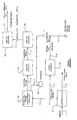
- prior art Figure 1 is provided in which a processing plant has a configuration with parallel independent injection gas compression and sales gas treating/compression, and in which an amine treating unit is upstream of a sales gas compressor.
- the feed gas (stream 1) is an associated gas from a crude oil production facility with a typical flow rate of about 8 BSCFD and at a feed pressure of about 4136 kPa 600 psig.
- the feed gas is first processed in a liquid recovery unit 101 in which the feed gas is dehydrated to -40°C -40°F water dew-point and in which most of the C5 + components are removed.
- the liquid recovery unit typically uses a lean oil absorption unit for the removal of the heavier hydrocarbons, which are recovered as stream 2.
- the so formed C5 + depleted gas (stream 3) from the liquid recovery unit is split into two portions, streams 4 and 5, which are separately used for gas injection and for sales gas production.
- Stream 5 at a flow rate of 4 BSCFD is treated for removal of carbon dioxide in an acid gas removal unit 102 operating at about 4136 kPa 600 psig that typically employs an activated MDEA absorption process.
- activated MDEA refers to a solvent comprising MDEA (methyldiethanolamine) and at least one primary and/or secondary amine, or piperazine.
- Treated gas (stream 6) leaving the acid gas removal unit is typically saturated with water from the absorption process.
- a sales gas dehydration unit 104 removes most of the water to form treated and dehydrated sales gas stream 11, which is compressed using sales gas compressors 105 to about 17.236 kPa 2500 psig (where a high-pressure pipeline is employed).
- the compressed sales gas 12 leaving the sales gas compressors has typically a temperature of about 37°C 100°F, which requires in a cold environment further cooling to about -1°C 30°F in a sales gas refrigeration unit 106 to protect a permafrost layer.
- the so cooled and compressed sales gas is then transported to a high-pressure pipeline via stream 13.
- the carbon dioxide stream (stream 7) is dried and compressed in the CO 2 injection compressor 103 to form stream 8 for injection to the reservoir formation, typically at 26.200 kPa 3800 psig (and typically in combination with compressed associated gas stream 9).
- the activated MDEA absorption process requires extensive heating and cooling for solvent regeneration. Moreover, the water losses from the MDEA absorption unit are relatively high as the treated gas (stream 6) and the carbon dioxide stream (stream 7) are saturated with water. Consequently, a relatively large quantity of makeup water is required to maintain proper solvent concentration.
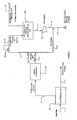
- a oil/gas facility has an exemplary configuration in which injection gas compression is followed by a sales gas treating unit using a physical solvent absorption process at high pressure, thereby rendering the associated gas flow rate independent from the rate of production of sales gas.
- the feed gas 1 and liquid recovery unit 101 With respect to the feed gas 1 and liquid recovery unit 101, the same configurations and considerations as described above apply.
- a C5 + liquid stream 2 leaves the plant via a liquid pipeline.
- stream 3 (at about 4136 kPa 600 psig) leaving the liquid recovery unit is typically not split into a sales gas branch and an injection gas branch. Therefore, all or almost all of the total flow of the dried and C5 + depleted gas (stream 3) from the liquid recovery is compressed in the injection gas compressors 107, boosting the gas pressure from about 4136 kPa 600 psig to about 26.200 kPa 3800 psig to form compressed stream 4.
- Compressed stream 4 is then split into at least two streams 9 (injection gas branch) and 5 (sales gas branch). Under normal operating conditions, stream 9 is routed directly to the injection reservoir at a flow rate of 4 BSCFD.
- the injection gas flow can be varied and can be increased up to 8 BSCFD when the sales gas market demand drops.
- Stream 5 typically at a flow rate of 4 BSCFD is let down in pressure to about 17305 kPa 2510 psig in the JT valve 106.
- the letdown gas (stream 6) is cooled by Joule-Thomson effect to about 24°C 76°F and fed to the an acid gas removal unit 102 that employs a physical solvent (e.g. , FLUOR SOLVENT TM ) for carbon dioxide removal operating at about 17.236 kPa 2500 psig.
- Carbon dioxide leaves the acid gas removal unit as stream 7 is further compressed in compressor 103 to compressed stream 8 at about injection pressure.
- the so formed compressed CO 2 stream may then be combined with the injection gas stream 9 to form combines stream 10 that is injected into the hydrocarbon reservoir ( i.e., the hydrocarbon reservoir formation).
- contemplated configurations operate at an elevated pressure using a physical solvent (or solvent comprising a physical solvent), which is particularly advantageous where the acid gas removal is performed at relatively high pressure because rich solvent loading of physical solvents increases proportionally to the acid gas partial pressure in the feed gas (Henry's Law). Consequently, a high acid gas partial pressure is especially beneficial as it will reduce the overall solvent circulation and energy consumption.
- the removal rate of associated gas from the feed gas can be maintained at a relatively constant rate and will therefore not be dependent on sales gas market demand.
- the sales gas market demand is low, more gas will be bypassed to the injection well, maintaining the necessary gas removal rate.
- contemplated processes are capable of maintaining a stable crude oil production independent of the sales gas market.
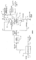
- FIG. 3 depicts an exemplary configuration in which a portion of the compressed gas from the injection compressors is treated with a physical solvent to remove at least a portion of the acid gas.
- feed gas 1 and liquid recovery unit 101 the same configurations and considerations as described above apply.
- a C5 + liquid stream 2 leaves the plant via a liquid pipeline.
- stream 3 (at about 4136 kPa 600 psig) leaving the liquid recovery unit is typically not split into a sales gas branch and an injection gas branch. Therefore, all or almost all of the total flow of the dried and C5 + depleted gas (stream 3) from the liquid recovery is compressed in the injection gas compressors 107, boosting the gas pressure from about 4136 kPa 600 psig to about 26200 kPa 3800 psig to form compressed stream 4. Compressed stream 4 is then split into at least two streams 9 (injection gas branch) and 5 (sales gas branch).
- Stream 5 is then reduced in pressure by pressure letdown in a turbo expander 108 that produces an expanded gas (stream 14) at about 10.342 kPa 1500 psig and -12°C 10°F.
- the expanded gas is fed to the acid gas removal unit using a physical solvent for acid gas absorption operating at about 10.342 kPa 1500 psig.
- a physical solvent process provides various advantages over known amine treating processes as described above.
- the expanded gas stream 14 will have a temperature of about -12°C 10°F, thereby further reducing cooling requirements of the physical solvent absorption process.
- the treated gas (stream 15) from the acid gas removal unit 102 is typically at about 10.273kPa 1490 psig and -28°C -20°F, wherein the refrigerant content of stream 15 is employed to cool the outlet stream 19 from expander/compressor after cooler 110 in a heat recovery exchanger 109.
- the heated gas stream 17 from exchanger 109 is further compressed by the expander compressor 108 to 17236 kPa 2500 psig and cooled by aftercooler 110 to form stream 19 which is further cooled to stream 13 by heat recovery exchanger 109 to -1°C 30°F.
- Such configurations may also (optionally or additionally) be employed to produce a second sales gas (stream 18) at an intermediate pressure (e.g ., about 10.342 kPa 1500 psig), which may be produced directly from the acid gas removal unit prior to the expander compressor 108.
- an intermediate pressure e.g ., about 10.342 kPa 1500 psig
- the acid gas that is removed from the acid gas removal unit 102 leaves the removal unit as stream 7 and is compressed by injection compressor 103 for injection into the hydrocarbon reservoir.
- the compressed acid stream 8 gas may be combined with the compressed injection gas stream 9.
- gas injection and sales gas production is performed with the use of a turbo expander that allows the physical solvent absorption unit to operate at a pressure that is lower than the sales gas pipeline
- the optimum absorption pressure of a physical solvent process depends on several factors such as the acid gas concentration in the feed gas, the physical and chemical properties of the solvent and the heat and mass transfer inside the solvent absorber at the operating pressure).
- the pressure required for optimum configuration and operation may also be lower than the sales gas pressure (e.g., about 10.342 kPa 1500 psig or lower).
- contemplated configurations according to Figure 3 will exhibit substantially the same advantages as contemplated configurations according to Figure 2, and a particularly advantage includes a relatively constant removal rate of the associated gas, which is substantially independent from the sales gas market demand. For example, when the sales gas market is low, more associated gas is bypassed into the injection well. As a result, contemplated processes allow a relatively unchanged crude oil production despite a continuously changing sales gas market.
- contemplated configurations may be modified to employ a chemical solvent for acid gas removal (e.g., using activated and/or formulated MDEA).
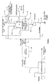
- Figure 4 depicts an exemplary configuration in which a portion of the compressed gas from the injection compressors is treated with activated MDEA solvent to remove at least some of the acid gas.
- the feed gas 1 and liquid recovery unit 101 the same configurations and considerations as described above apply.
- a C5 + liquid stream 2 leaves the plant via a liquid pipeline.
- Stream 3 (at about 4136 kPa 600 psig) leaving the liquid recovery unit is typically not split into a sales gas branch and an injection gas branch. Therefore, all or almost all of the total flow of the dried and C5 + depleted gas (stream 3) from the liquid recovery is compressed in the injection gas compressors 107, boosting the gas pressure from about 4136 kPa 600 psig to about 26200 kPa 3800 psig to form compressed stream 4. Compressed stream 4 is then split into at least two streams 9 (injection gas branch) and 5 (sales gas branch).
- Stream 5 is reduced in pressure by pressure letdown in a turbo expander 108 that produces an expanded gas (stream 14) at about 10.342 kPa 1500 psig and -12°C 10°F.
- the refrigerant content of the expanded gas (Stream 14) may then be used to provide cooling for stream 19, the outlet stream from the expander compressor aftercooler 110.
- stream 19 is cooled to -1°C 30°F (stream 13) for pipeline transmission while stream 14 is heated to about 37°C 100°F to 54°C 130°F (stream 20) before being fed to the acid gas removal unit 102 operating at about 10.342 kPa 1500 psig.
- the feed temperature to the amine absorber can be varied by this exchange configuration to meet the optimum operating conditions considering the solvent's chemical and physical properties, concentrations and the heat and mass transfer performance in the absorber.
- an activated MDEA When compared to other amines (primary or secondary amines) in an acid gas removal unit, the use of an activated MDEA generally requires less circulation, heating and cooling duties due to the fact that a higher amine loading can be achieved with MDEA.
- the activated NIDEA process operates at a higher temperature and requires higher heating and cooling duties.
- the treated gas from the MDEA absorber is saturated with water and requires further gas dehydration (in order to avoid condensation in pipeline) prior to being compressed by the expander compressor 108 to pipeline pressure.
- Such configurations may also (optionally or additionally) be employed to produce a second sales gas (stream 18) at an intermediate pressure (e.g. , about 10.342 kPa 1500 psig), which may be produced directly from the acid gas removal unit prior to the expander compressor 108 ( e.g. , from stream 15).
- the treated gas from acid gas removal unit 102 (stream 17) is then compressed to the desired high pressure (here: about 17.236 kPa 2500 psig).
- the acid gas that is removed from the acid gas removal unit 102 leaves the removal unit as stream 7 and is dried and compressed by CO2 injection compressor 103 for injection into the hydrocarbon reservoir.
- the compressed acid gas stream 8 may be combined with the compressed injection gas stream 9 to form combined injection gas stream 10.
- gas injection and sales gas production is performed with the use of a turbo expander that allows the MDEA absorption unit to operate at a pressure that is lower than the sales gas pipeline.
- the optimum absorption pressure of a MDEA process depends on several factors, including the acid gas concentration in the feed gas, the physical and chemical properties of the solvent and the heat and mass transfer inside the solvent absorber at the operating pressure, etc.).
- the pressure required for optimum configuration and operation may also be lower than the sales gas pressure (e.g. , about 10.342 kPa 1500 psig or lower).
- contemplated configurations according to Figure 4 will exhibit substantially the same advantages as contemplated configurations according to Figure 2 or 3.
- the removal rate of the associated gas will be substantially independent from the sales gas market demand. For example, when the sales gas market is low, more associated gas is bypassed into the injection well. As a result, contemplated processes allow a relatively unchanged crude oil production despite a continuously changing sales gas market.
- gas streams With respect to gas streams (stream 1), it is generally contemplated that numerous natural and synthetic gases are appropriate. However, particularly preferred gases include associated gas from oil production after C5 + components have been removed, and especially associated gas with a carbon dioxide content that is at least about 5 mol%, more typically at least 10 about mol%, and most typically at least 10 to 20 mol%. Therefore, particularly suitable feed streams include natural gas feed streams from oil and gas fields located in Alaska, Norway, Southeast Asia, and the Gulf of Mexico. A typical feed gas composition is given in the table below: COMPONENT MOL% N 2 0.6 CO 2 14.50 H 2 S 100 ppm C1 78.3 C2 4.9 C3 1.4 C4 0.2 C5 + 0.1
- solvents in the acid gas removal unit may or may not exhibit specificity towards a particular acid gas. Consequently, particularly suitable solvents include FLUOR SOLVENT TM (propylene carbonate), MORPHYSORB TM (a morpholine solvent), and SELEXOL TM (a dimethylether of polyethylene glycol).
- FLUOR SOLVENT TM propylene carbonate
- MORPHYSORB TM a morpholine solvent
- SELEXOL TM a dimethylether of polyethylene glycol
- Other acid gas removal solvents that are particularly suitable to be used in contemplated configurations include activated MDEA, formulated MDEA and other amine solvents.
- a plant may include an acid gas removal unit that receives a portion of the dehydrated and C5+ depleted gas from an injection gas compressor at a pressure above a pipeline pressure (e.g., high-pressure pipelines of at least 15.857 kPa 2300 psig), wherein the dehydrated and C5 + depleted gas comprises a sales gas and an acid gas, and wherein the acid gas is removed by a physical solvent or chemical solvent in the acid gas removal unit.
- a pipeline pressure e.g., high-pressure pipelines of at least 15.857 kPa 2300 psig
- the dehydrated and C5 + depleted gas has a carbon dioxide content of at least 10 mol% and a water dew point of about -40°C -40°F.
- the carbon dioxide content may vary considerably (see above), and it is especially preferred that the dehydrated and C5+ depleted gas may further be C4 + depleted.
- the C5 + depleted gas is let down in pressure to about pipeline pressure ( e.g. , via JT valve or turbo expander) before the acid gas is removed in the acid gas removal unit, and it is especially preferred that the dehydrated and C5+ depleted gas is let down in a turbo expander to a pressure at which the acid gas removal unit operates.
- the acid gas removal unit will be operated at similar or substantially same pressure. Consequently, it should be appreciated that the pressure at which the acid gas removal unit operates is lower than the pipeline pressure, but above the pressure at which the gas enters the injection compressors (which is typically at about 4136 kPa 600 psig). Consequently, and especially where the acid gas removal unit operates at an intermediate pressure ( e.g ., at about 10.342 kPa 1500 psig), it is contemplated that the C5 + depleted gas that leaves the acid gas removal unit may be compressed to pipeline pressure (e.g.
- the refrigerant content of the C5 + depleted gas that leaves the acid gas removal unit may advantageously be used as a refrigerant ( e.g., to cool the sales gas).
- a bypass will receive at least a portion of the dehydrated and C5 + depleted gas from the injection gas compressor at a pressure above pipeline pressure that is subsequently injected to a reservoir formation.
- the volume flow through such bypass lines it should be recognized that the volume of flow may be varied during operation of the plant to adjust for fluctuations in the sales gas demand. Therefore, when the sales gas demand is relatively high, a relatively small fraction of the dehydrated and C5 + depleted gas from the injection gas compressor is injected into the formation. On the other hand, when the sales gas demand is relatively low, it is contemplated that the fraction of the dehydrated and C5 + depleted gas may be up to 100% of the total flow rate of the dehydrated and C5 + depleted gas. Therefore, it should be appreciated that the flow of sales gas and with that the production rate of crude hydrocarbon product may be varied without a concomitant change in the flow rate of the production rate of crude hydrocarbon product.
- an injection gas compression unit that receives a dehydrated gas comprising an acid gas and compresses the dehydrated gas to an injection pressure, thereby forming a compressed gas.
- An acid gas removal unit receives a first portion of the compressed gas, wherein at least some of the acid gas is removed in the acid gas removal unit at at least pipeline pressure using a physical solvent, or chemical solvent to form a sales gas, and the sales gas is fed to a pipeline, the removed acid gas is compressed and injected to a reservoir formation, and wherein optionally a second portion of the compressed gas is injected to the reservoir formation for disposal or enhanced oil recovery.
- the sales gas pipeline pressure, and the physical solvent or chemical solvent the same considerations as contemplated above apply.
- contemplated plants may include a hydrocarbon source that provides at a production rate a crude hydrocarbon product and an associated gas comprising a sales gas and an acid gas.
- An injection gas compression unit in such plants will receive and compress at least a portion of the associated gas, thereby producing a compressed associated gas
- an acid gas removal unit may be fluidly coupled to the injection gas compression unit and receive at least part of the compressed associated gas via JT valve or turbo expander, thereby separating the acid gas from the sales gas.
- Contemplated plants may further include a bypass that is fluidly coupled to the injection gas compression unit and receives a portion of the compressed associated gas, thereby rendering the production rate of the crude hydrocarbon product independent from the flow rate of the sales gas.
- Particularly preferred plant may include an oil/gas production facility in which the associated gas is dehydrated and C5 + depleted to form a treated gas with a carbon dioxide content of at least 10 mol% and a water dew point of about -40°C -40°F.
- the injection gas compression unit in such plants compresses the treated gas to a pressure above a sales gas pipeline pressure (and preferably to a pressure of at least 24131 kPa 3500 psig), and that the acid gas removal unit operates at or below a pressure of about sales gas pipeline pressure (which may be about 10.342 kPa 1500 psig or 17236 kPa 2500 psig).
Landscapes
- Chemical & Material Sciences (AREA)
- Engineering & Computer Science (AREA)
- Analytical Chemistry (AREA)
- General Chemical & Material Sciences (AREA)
- Oil, Petroleum & Natural Gas (AREA)
- Chemical Kinetics & Catalysis (AREA)
- Health & Medical Sciences (AREA)
- Biomedical Technology (AREA)
- Environmental & Geological Engineering (AREA)
- Gas Separation By Absorption (AREA)
- Treating Waste Gases (AREA)
- Structures Of Non-Positive Displacement Pumps (AREA)
Claims (11)
- Eine Anlage umfassend:einen Injektionsgaskompressor (107) ausgestaltet zum Komprimieren eines dehydrierten und C5+ abgereicherten Gases auf einen Druck oberhalb eines Pipelinedruckes;eine Sauergasentfernungseinheit (102), die Fluid leitend mit dem Injektionsgaskompressor (107) verbunden ist, und die ausgestaltet ist vom Injektionsgaskompressor (107) einen ersten Teil des dehydrierten und C5+ abgereicherten Gases zu erhalten;wobei die Sauergasentfernungseinheit (102) zudem ausgestaltet ist zum Entfernen eines Sauergases vom ersten Teil des dehydrierten und C5+ abgereicherten Gases, um dadurch unter Verwendung eines physikalischen oder chemischen Lösungsmittels ein Verkaufsgas zu erzeugen; undeine Leitung (9), die Fluid leitend mit dem Injektionsgaskompressor (107) verbunden ist, und die ausgestaltet ist zum Weiterleiten eines zweiten Teils des komprimierten, dehydrierten und C5+ abgereicherten Gases an einen Injektionskopf eines Speichergebildes.
- Anlage gemäss Anspruch 1, wobei die Sauergasentfernungseinheit (102) ausgestaltet ist zum Entfernen des Sauergases bei etwa Pipelinedruck.
- Anlage gemäss Anspruch 1, wobei die Sauergasentfernungseinheit (102) ausgestaltet ist zum Entfernen des Sauergases bei einem Druck von zumindest dem Pipelinedruck.
- Anlage gemäss Anspruch 1, weiter umfassend einen Expanderkompressor (108), wobei der Expander ausgestaltet ist zum Reduzieren des Drucks des von Injektionskompressor (107) kommenden, C5+ abgereicherten Gases, auf Sauergasentfernungsdruck, und wobei der Expanderkompressor (108) weiter ausgestaltet ist zum Komprimieren des Gases, welches die Sauergasentfernungsvorrichtung (102) verlässt, auf einen Pipelinedruck.
- Anlage gemäss einem der Ansprüche 1 bis 4, wobei das dehydrierte und C5+ abgereicherte Gas einen Karbondioxydanteil von zumindest 10 mol% und einen Wassertaupunkt von etwa -40°C (-40°F) aufweist.
- Anlage gemäss Anspruch 5, wobei das dehydrierte und C5+ abgereicherte Gas zudem C4+ abgereichert ist.
- Anlage gemäss einem der Ansprüche 1 bis 4, wobei das physikalische Lösungsmittel ausgewählt ist aus der Gruppe Propylenkarbonat, ein morpholines Lösungsmittel, und ein Dimethylether aus Polyethylenglykol, und wobei das chemische Lösungsmittel MDEA umfasst.
- Anlage gemäss einem der Ansprüche 1 bis 2, wobei der Pipelinedruck zumindest 15'857 kPa (2300 psig) beträgt.
- Anlage gemäss Anspruch 1, umfassend einen Wärmetauscher (109) der ausgestaltet ist zum Verwenden des Kühlungsinhaltes des C5+ abgereicherte Gas, das die Sauergasentfernungseinheit (02) verlässt, um dadurch den Kompressorauslassstrom umfassend das C5+ abgereicherte Gas zu kühlen.
- Anlage gemäss einem der vorhergehenden Ansprüche, wobei der erste Anteil des dehydrierten und C5+ abgereicherten Gases bis zu 100% der gesamten Flussrate des dehydrierten und C5+ abgereicherten Gases entspricht.
- Anlage gemäss einem der vorhergehenden Ansprüche, wobei das Sauergas, welches durch die Sauergasentfernungseinheit (102) entfernt wurde, verdichtet wird und in ein Speichergebildes eingespeist wird.
Applications Claiming Priority (1)
| Application Number | Priority Date | Filing Date | Title |
|---|---|---|---|
| PCT/US2002/038107 WO2004047956A1 (en) | 2002-11-25 | 2002-11-25 | High pressure gas processing configurations and methods |
Publications (3)
| Publication Number | Publication Date |
|---|---|
| EP1565247A1 EP1565247A1 (de) | 2005-08-24 |
| EP1565247A4 EP1565247A4 (de) | 2006-05-24 |
| EP1565247B1 true EP1565247B1 (de) | 2008-01-09 |
Family
ID=32391453
Family Applications (1)
| Application Number | Title | Priority Date | Filing Date |
|---|---|---|---|
| EP02782390A Expired - Lifetime EP1565247B1 (de) | 2002-11-25 | 2002-11-25 | Hochdruckgasverarbeitungsconfigurationen |
Country Status (8)
| Country | Link |
|---|---|
| US (1) | US7204867B2 (de) |
| EP (1) | EP1565247B1 (de) |
| JP (1) | JP4272164B2 (de) |
| CN (1) | CN1331564C (de) |
| AT (1) | ATE383192T1 (de) |
| CA (1) | CA2505522C (de) |
| DE (1) | DE60224591D1 (de) |
| WO (1) | WO2004047956A1 (de) |
Families Citing this family (36)
| Publication number | Priority date | Publication date | Assignee | Title |
|---|---|---|---|---|
| JP4634384B2 (ja) * | 2005-04-04 | 2011-02-16 | 三菱重工業株式会社 | 吸収液、co2又はh2s又はその双方の除去方法及び装置 |
| NO325702B1 (no) * | 2006-07-06 | 2008-07-07 | Compressed Energy Tech As | System, fartøy og fremgangsmåte for produksjon av olje og tyngre gassfraksjoner fra et reservoar under havbunnen |
| US7901488B2 (en) * | 2006-10-04 | 2011-03-08 | Board Of Regents, The University Of Texas System | Regeneration of an aqueous solution from an acid gas absorption process by matrix stripping |
| CA2674618C (en) | 2007-01-19 | 2015-02-10 | Exxonmobil Upstream Research Company | Integrated controlled freeze zone (cfz) tower and dividing wall (dwc) for enhanced hydrocarbon recovery |
| PL2117682T3 (pl) * | 2007-02-22 | 2013-03-29 | Fluor Tech Corp | Konfiguracje do produkcji dwutlenku węgla i wodoru ze strumieni zgazowywania |
| AU2008254961B2 (en) * | 2007-05-18 | 2012-03-29 | Exxonmobil Upstream Research Company | Temperature swing adsorption of CO2 from flue gas utilizing heat from compression |
| JP5215595B2 (ja) | 2007-06-18 | 2013-06-19 | 三菱重工業株式会社 | 吸収液、吸収液を用いたco2又はh2s除去装置及び方法 |
| WO2009020473A1 (en) * | 2007-08-09 | 2009-02-12 | Fluor Technologies Corporation | Configurations and methods for fuel gas treatment with total sulfur removal and olefin saturation |
| US8404027B2 (en) | 2008-11-04 | 2013-03-26 | Alstom Technology Ltd | Reabsorber for ammonia stripper offgas |
| MY155414A (en) | 2009-04-20 | 2015-10-15 | Exxonmobil Upstream Res Co | Cryogenic system for removing acid gases from a hydrocarbon gas stream, and method of removing acid gases |
| MY161120A (en) | 2009-09-09 | 2017-04-14 | Exxonmobil Upstream Res Co | Cryogenic system for removing acid gases from a hydrocarbon gas stream |
| BR112012017599A2 (pt) | 2010-01-22 | 2016-08-16 | Exxonmobil Upstream Res Co | remoção de gases ácidos de um fluxo de gás, com captura e sequestro de co2 |
| SG182399A1 (en) | 2010-02-03 | 2012-08-30 | Exxonmobil Upstream Res Co | Systems and methods for using cold liquid to remove solidifiable gas components from process gas streams |
| MX362706B (es) | 2010-07-30 | 2019-02-01 | Exxonmobil Upstream Res Company Star | Sistemas criogenicos para remover gases acidos de una corriente de gas de hidrocarburo que usan dispositivos de separacion de co-corriente. |
| WO2012166879A1 (en) * | 2011-06-03 | 2012-12-06 | Greatpoint Energy, Inc. | Hydromethanation of a carbonaceous feedstock |
| US9162177B2 (en) | 2012-01-25 | 2015-10-20 | Alstom Technology Ltd | Ammonia capturing by CO2 product liquid in water wash liquid |
| CA2867287C (en) | 2012-03-21 | 2019-06-11 | Exxonmobil Upstream Research Company | Separating carbon dioxide and ethane from a mixed stream |
| US9604889B2 (en) * | 2012-11-08 | 2017-03-28 | Energy Recovery, Inc. | Isobaric pressure exchanger in amine gas processing |
| US9447996B2 (en) | 2013-01-15 | 2016-09-20 | General Electric Technology Gmbh | Carbon dioxide removal system using absorption refrigeration |
| MY177768A (en) | 2013-12-06 | 2020-09-23 | Exxonmobil Upstream Res Co | Method and device for separating hydrocarbons and contaminants with a heating mechanism to destabilize and/or prevent adhesion of solids |
| WO2015084497A2 (en) | 2013-12-06 | 2015-06-11 | Exxonmobil Upstream Research Company | Method and system of dehydrating a feed stream processed in a distillation tower |
| MY176633A (en) | 2013-12-06 | 2020-08-19 | Exxonmobil Upstream Res Co | Method and system of modifiying a liquid level during start-up operations |
| WO2015084494A2 (en) | 2013-12-06 | 2015-06-11 | Exxonmobil Upstream Research Company | Method and device for separating hydrocarbons and contaminants with a spray assembly |
| WO2015084495A2 (en) | 2013-12-06 | 2015-06-11 | Exxonmobil Upstream Research Company | Method and system of maintaining a liquid level in a distillation tower |
| US10139158B2 (en) | 2013-12-06 | 2018-11-27 | Exxonmobil Upstream Research Company | Method and system for separating a feed stream with a feed stream distribution mechanism |
| US9562719B2 (en) | 2013-12-06 | 2017-02-07 | Exxonmobil Upstream Research Company | Method of removing solids by modifying a liquid level in a distillation tower |
| US9874395B2 (en) | 2013-12-06 | 2018-01-23 | Exxonmobil Upstream Research Company | Method and system for preventing accumulation of solids in a distillation tower |
| US9829247B2 (en) | 2013-12-06 | 2017-11-28 | Exxonmobil Upstream Reseach Company | Method and device for separating a feed stream using radiation detectors |
| US8986640B1 (en) | 2014-01-07 | 2015-03-24 | Alstom Technology Ltd | System and method for recovering ammonia from a chilled ammonia process |
| EA201791687A1 (ru) | 2015-02-27 | 2017-12-29 | Эксонмобил Апстрим Рисерч Компани | Снижение тепловой нагрузки и нагрузки по дегидратации подаваемого потока, поступающего в процесс криогенной перегонки |
| CA2994812C (en) | 2015-09-18 | 2020-03-10 | Exxonmobil Upstream Research Company | Heating component to reduce solidification in a cryogenic distillation system |
| CA2998466C (en) | 2015-09-24 | 2021-06-29 | Exxonmobil Upstream Research Company | Treatment plant for hydrocarbon gas having variable contaminant levels |
| CA3024545C (en) | 2016-03-30 | 2020-08-25 | Exxonmobile Upstream Research Company | Self-sourced reservoir fluid for enhanced oil recovery |
| WO2020005553A1 (en) | 2018-06-29 | 2020-01-02 | Exxonmobil Upstream Research Company (Emhc-N1.4A.607) | Mixing and heat integration of melt tray liquids in a cryogenic distillation tower |
| WO2020005552A1 (en) | 2018-06-29 | 2020-01-02 | Exxonmobil Upstream Research Company | Hybrid tray for introducing a low co2 feed stream into a distillation tower |
| US12325634B2 (en) | 2021-04-23 | 2025-06-10 | Fluor Technologies Corporation | Production of ammonia, methanol, and synthesis products from one or more gasification products |
Family Cites Families (12)
| Publication number | Priority date | Publication date | Assignee | Title |
|---|---|---|---|---|
| US3065790A (en) * | 1957-11-22 | 1962-11-27 | Pure Oil Co | Oil recovery process |
| US3300324A (en) * | 1963-05-20 | 1967-01-24 | Mobil Oil Corp | Hydrogen sulfide detection method and control system |
| US3442332A (en) * | 1966-02-01 | 1969-05-06 | Percival C Keith | Combination methods involving the making of gaseous carbon dioxide and its use in crude oil recovery |
| US4382912A (en) * | 1981-09-10 | 1983-05-10 | Gulf Research & Development Company | Selective combusting of hydrogen sulfide in carbon dioxide injection gas |
| US4449994A (en) * | 1982-01-15 | 1984-05-22 | Air Products And Chemicals, Inc. | Low energy process for separating carbon dioxide and acid gases from a carbonaceous off-gas |
| US4576615A (en) * | 1984-08-20 | 1986-03-18 | The Randall Corporation | Carbon dioxide hydrocarbons separation process |
| FR2715692B1 (fr) * | 1993-12-23 | 1996-04-05 | Inst Francais Du Petrole | Procédé de prétraitement d'un gaz naturel contenant de l'hydrogène sulfure. |
| US5769165A (en) * | 1996-01-31 | 1998-06-23 | Vastar Resources Inc. | Method for increasing methane recovery from a subterranean coal formation by injection of tail gas from a hydrocarbon synthesis process |
| US6203599B1 (en) * | 1999-07-28 | 2001-03-20 | Union Carbide Chemicals & Plastics Technology Corporation | Process for the removal of gas contaminants from a product gas using polyethylene glycols |
| US6183540B1 (en) * | 1999-08-27 | 2001-02-06 | Kinder Morgan, Inc. | Method and apparatus for removing aromatic hydrocarbons from a gas stream prior to an amine-based gas sweetening process |
| FR2808223B1 (fr) * | 2000-04-27 | 2002-11-22 | Inst Francais Du Petrole | Procede de purification d'un effluent contenant du gaz carbonique et des hydrocarbures par combustion |
| DE10136484A1 (de) * | 2001-07-27 | 2003-02-13 | Uhde Gmbh | Verfahren zur Entfernung von Gasbestandteilen aus technischen Gasen mittels Ethylenglykoldimethylethern bei tieferen Temperaturen |
-
2002
- 2002-11-25 EP EP02782390A patent/EP1565247B1/de not_active Expired - Lifetime
- 2002-11-25 JP JP2004555241A patent/JP4272164B2/ja not_active Expired - Fee Related
- 2002-11-25 CA CA002505522A patent/CA2505522C/en not_active Expired - Fee Related
- 2002-11-25 US US10/478,390 patent/US7204867B2/en not_active Expired - Fee Related
- 2002-11-25 AT AT02782390T patent/ATE383192T1/de not_active IP Right Cessation
- 2002-11-25 WO PCT/US2002/038107 patent/WO2004047956A1/en not_active Ceased
- 2002-11-25 DE DE60224591T patent/DE60224591D1/de not_active Expired - Lifetime
- 2002-11-25 CN CNB028299574A patent/CN1331564C/zh not_active Expired - Fee Related
Also Published As
| Publication number | Publication date |
|---|---|
| EP1565247A4 (de) | 2006-05-24 |
| US7204867B2 (en) | 2007-04-17 |
| DE60224591D1 (de) | 2008-02-21 |
| EP1565247A1 (de) | 2005-08-24 |
| JP2006507389A (ja) | 2006-03-02 |
| US20050211092A1 (en) | 2005-09-29 |
| WO2004047956A1 (en) | 2004-06-10 |
| AU2002348259B2 (en) | 2007-03-15 |
| AU2002348259A1 (en) | 2004-06-18 |
| CA2505522C (en) | 2009-07-07 |
| ATE383192T1 (de) | 2008-01-15 |
| CN1694753A (zh) | 2005-11-09 |
| CA2505522A1 (en) | 2004-06-10 |
| JP4272164B2 (ja) | 2009-06-03 |
| CN1331564C (zh) | 2007-08-15 |
Similar Documents
| Publication | Publication Date | Title |
|---|---|---|
| EP1565247B1 (de) | Hochdruckgasverarbeitungsconfigurationen | |
| EP1569740B1 (de) | Verfahren zur enfernung von saurem gas | |
| AU2002325051B2 (en) | Configurations and methods of acid gas removal | |
| CA2482159C (en) | Configurations and methods for improved acid gas removal | |
| US7192468B2 (en) | Configurations and method for improved gas removal | |
| US10384160B2 (en) | Configurations and methods of high pressure acid gas removal in the production of ultra-low sulfur gas | |
| US9114351B2 (en) | Configurations and methods for high pressure acid gas removal | |
| AU2002348259C1 (en) | High pressure gas processing configurations and methods | |
| AU2007201677B2 (en) | Configurations and methods for improved acid gas removal | |
| Guvelioglu et al. | H2S Removal from CO2 by Distillation |
Legal Events
| Date | Code | Title | Description |
|---|---|---|---|
| PUAI | Public reference made under article 153(3) epc to a published international application that has entered the european phase |
Free format text: ORIGINAL CODE: 0009012 |
|
| 17P | Request for examination filed |
Effective date: 20050602 |
|
| AK | Designated contracting states |
Kind code of ref document: A1 Designated state(s): AT BE BG CH CY CZ DE DK EE ES FI FR GB GR IE IT LI LU MC NL PT SE SK TR |
|
| AX | Request for extension of the european patent |
Extension state: AL LT LV MK RO SI |
|
| DAX | Request for extension of the european patent (deleted) | ||
| A4 | Supplementary search report drawn up and despatched |
Effective date: 20060410 |
|
| RAP1 | Party data changed (applicant data changed or rights of an application transferred) |
Owner name: FLUOR CORPORATION |
|
| 17Q | First examination report despatched |
Effective date: 20060920 |
|
| GRAP | Despatch of communication of intention to grant a patent |
Free format text: ORIGINAL CODE: EPIDOSNIGR1 |
|
| GRAS | Grant fee paid |
Free format text: ORIGINAL CODE: EPIDOSNIGR3 |
|
| GRAA | (expected) grant |
Free format text: ORIGINAL CODE: 0009210 |
|
| AK | Designated contracting states |
Kind code of ref document: B1 Designated state(s): AT BE BG CH CY CZ DE DK EE ES FI FR GB GR IE IT LI LU MC NL PT SE SK TR |
|
| REG | Reference to a national code |
Ref country code: GB Ref legal event code: FG4D |
|
| REG | Reference to a national code |
Ref country code: CH Ref legal event code: EP |
|
| REG | Reference to a national code |
Ref country code: IE Ref legal event code: FG4D |
|
| REF | Corresponds to: |
Ref document number: 60224591 Country of ref document: DE Date of ref document: 20080221 Kind code of ref document: P |
|
| PG25 | Lapsed in a contracting state [announced via postgrant information from national office to epo] |
Ref country code: CH Free format text: LAPSE BECAUSE OF FAILURE TO SUBMIT A TRANSLATION OF THE DESCRIPTION OR TO PAY THE FEE WITHIN THE PRESCRIBED TIME-LIMIT Effective date: 20080109 Ref country code: LI Free format text: LAPSE BECAUSE OF FAILURE TO SUBMIT A TRANSLATION OF THE DESCRIPTION OR TO PAY THE FEE WITHIN THE PRESCRIBED TIME-LIMIT Effective date: 20080109 Ref country code: ES Free format text: LAPSE BECAUSE OF FAILURE TO SUBMIT A TRANSLATION OF THE DESCRIPTION OR TO PAY THE FEE WITHIN THE PRESCRIBED TIME-LIMIT Effective date: 20080420 Ref country code: FI Free format text: LAPSE BECAUSE OF FAILURE TO SUBMIT A TRANSLATION OF THE DESCRIPTION OR TO PAY THE FEE WITHIN THE PRESCRIBED TIME-LIMIT Effective date: 20080109 |
|
| REG | Reference to a national code |
Ref country code: CH Ref legal event code: PL |
|
| PG25 | Lapsed in a contracting state [announced via postgrant information from national office to epo] |
Ref country code: AT Free format text: LAPSE BECAUSE OF FAILURE TO SUBMIT A TRANSLATION OF THE DESCRIPTION OR TO PAY THE FEE WITHIN THE PRESCRIBED TIME-LIMIT Effective date: 20080109 Ref country code: BG Free format text: LAPSE BECAUSE OF FAILURE TO SUBMIT A TRANSLATION OF THE DESCRIPTION OR TO PAY THE FEE WITHIN THE PRESCRIBED TIME-LIMIT Effective date: 20080409 |
|
| PG25 | Lapsed in a contracting state [announced via postgrant information from national office to epo] |
Ref country code: PT Free format text: LAPSE BECAUSE OF FAILURE TO SUBMIT A TRANSLATION OF THE DESCRIPTION OR TO PAY THE FEE WITHIN THE PRESCRIBED TIME-LIMIT Effective date: 20080609 Ref country code: BE Free format text: LAPSE BECAUSE OF FAILURE TO SUBMIT A TRANSLATION OF THE DESCRIPTION OR TO PAY THE FEE WITHIN THE PRESCRIBED TIME-LIMIT Effective date: 20080109 |
|
| EN | Fr: translation not filed | ||
| PG25 | Lapsed in a contracting state [announced via postgrant information from national office to epo] |
Ref country code: SK Free format text: LAPSE BECAUSE OF FAILURE TO SUBMIT A TRANSLATION OF THE DESCRIPTION OR TO PAY THE FEE WITHIN THE PRESCRIBED TIME-LIMIT Effective date: 20080109 Ref country code: SE Free format text: LAPSE BECAUSE OF FAILURE TO SUBMIT A TRANSLATION OF THE DESCRIPTION OR TO PAY THE FEE WITHIN THE PRESCRIBED TIME-LIMIT Effective date: 20080409 Ref country code: DK Free format text: LAPSE BECAUSE OF FAILURE TO SUBMIT A TRANSLATION OF THE DESCRIPTION OR TO PAY THE FEE WITHIN THE PRESCRIBED TIME-LIMIT Effective date: 20080109 Ref country code: CZ Free format text: LAPSE BECAUSE OF FAILURE TO SUBMIT A TRANSLATION OF THE DESCRIPTION OR TO PAY THE FEE WITHIN THE PRESCRIBED TIME-LIMIT Effective date: 20080109 |
|
| PLBE | No opposition filed within time limit |
Free format text: ORIGINAL CODE: 0009261 |
|
| STAA | Information on the status of an ep patent application or granted ep patent |
Free format text: STATUS: NO OPPOSITION FILED WITHIN TIME LIMIT |
|
| 26N | No opposition filed |
Effective date: 20081010 |
|
| PG25 | Lapsed in a contracting state [announced via postgrant information from national office to epo] |
Ref country code: DE Free format text: LAPSE BECAUSE OF FAILURE TO SUBMIT A TRANSLATION OF THE DESCRIPTION OR TO PAY THE FEE WITHIN THE PRESCRIBED TIME-LIMIT Effective date: 20080410 |
|
| PG25 | Lapsed in a contracting state [announced via postgrant information from national office to epo] |
Ref country code: FR Free format text: LAPSE BECAUSE OF FAILURE TO SUBMIT A TRANSLATION OF THE DESCRIPTION OR TO PAY THE FEE WITHIN THE PRESCRIBED TIME-LIMIT Effective date: 20081031 Ref country code: EE Free format text: LAPSE BECAUSE OF FAILURE TO SUBMIT A TRANSLATION OF THE DESCRIPTION OR TO PAY THE FEE WITHIN THE PRESCRIBED TIME-LIMIT Effective date: 20080109 |
|
| PG25 | Lapsed in a contracting state [announced via postgrant information from national office to epo] |
Ref country code: MC Free format text: LAPSE BECAUSE OF NON-PAYMENT OF DUE FEES Effective date: 20081130 |
|
| PG25 | Lapsed in a contracting state [announced via postgrant information from national office to epo] |
Ref country code: CY Free format text: LAPSE BECAUSE OF FAILURE TO SUBMIT A TRANSLATION OF THE DESCRIPTION OR TO PAY THE FEE WITHIN THE PRESCRIBED TIME-LIMIT Effective date: 20080109 |
|
| PG25 | Lapsed in a contracting state [announced via postgrant information from national office to epo] |
Ref country code: IT Free format text: LAPSE BECAUSE OF FAILURE TO SUBMIT A TRANSLATION OF THE DESCRIPTION OR TO PAY THE FEE WITHIN THE PRESCRIBED TIME-LIMIT Effective date: 20080109 |
|
| PG25 | Lapsed in a contracting state [announced via postgrant information from national office to epo] |
Ref country code: IE Free format text: LAPSE BECAUSE OF NON-PAYMENT OF DUE FEES Effective date: 20081125 |
|
| PG25 | Lapsed in a contracting state [announced via postgrant information from national office to epo] |
Ref country code: LU Free format text: LAPSE BECAUSE OF NON-PAYMENT OF DUE FEES Effective date: 20081125 |
|
| PG25 | Lapsed in a contracting state [announced via postgrant information from national office to epo] |
Ref country code: TR Free format text: LAPSE BECAUSE OF FAILURE TO SUBMIT A TRANSLATION OF THE DESCRIPTION OR TO PAY THE FEE WITHIN THE PRESCRIBED TIME-LIMIT Effective date: 20080109 |
|
| PG25 | Lapsed in a contracting state [announced via postgrant information from national office to epo] |
Ref country code: GR Free format text: LAPSE BECAUSE OF FAILURE TO SUBMIT A TRANSLATION OF THE DESCRIPTION OR TO PAY THE FEE WITHIN THE PRESCRIBED TIME-LIMIT Effective date: 20080410 |
|
| PGFP | Annual fee paid to national office [announced via postgrant information from national office to epo] |
Ref country code: NL Payment date: 20101110 Year of fee payment: 9 |
|
| REG | Reference to a national code |
Ref country code: NL Ref legal event code: V1 Effective date: 20120601 |
|
| PG25 | Lapsed in a contracting state [announced via postgrant information from national office to epo] |
Ref country code: NL Free format text: LAPSE BECAUSE OF NON-PAYMENT OF DUE FEES Effective date: 20120601 |
|
| PGFP | Annual fee paid to national office [announced via postgrant information from national office to epo] |
Ref country code: GB Payment date: 20141127 Year of fee payment: 13 |
|
| GBPC | Gb: european patent ceased through non-payment of renewal fee |
Effective date: 20151125 |
|
| PG25 | Lapsed in a contracting state [announced via postgrant information from national office to epo] |
Ref country code: GB Free format text: LAPSE BECAUSE OF NON-PAYMENT OF DUE FEES Effective date: 20151125 |