EP1565244B1 - Filter cartridge incorporating a peripheral compatibility matrix - Google Patents
Filter cartridge incorporating a peripheral compatibility matrix Download PDFInfo
- Publication number
- EP1565244B1 EP1565244B1 EP03773304A EP03773304A EP1565244B1 EP 1565244 B1 EP1565244 B1 EP 1565244B1 EP 03773304 A EP03773304 A EP 03773304A EP 03773304 A EP03773304 A EP 03773304A EP 1565244 B1 EP1565244 B1 EP 1565244B1
- Authority
- EP
- European Patent Office
- Prior art keywords
- shoulder
- cartridge
- filter cartridge
- roll seam
- filter
- Prior art date
- Legal status (The legal status is an assumption and is not a legal conclusion. Google has not performed a legal analysis and makes no representation as to the accuracy of the status listed.)
- Expired - Lifetime
Links
- 239000011159 matrix material Substances 0.000 title description 14
- 230000002093 peripheral effect Effects 0.000 title description 3
- 230000014759 maintenance of location Effects 0.000 claims description 35
- 238000004519 manufacturing process Methods 0.000 claims description 2
- 238000000034 method Methods 0.000 claims 7
- 239000000446 fuel Substances 0.000 description 15
- 238000006073 displacement reaction Methods 0.000 description 9
- 230000000295 complement effect Effects 0.000 description 8
- 238000001914 filtration Methods 0.000 description 8
- 239000002184 metal Substances 0.000 description 7
- 230000000717 retained effect Effects 0.000 description 6
- 230000000712 assembly Effects 0.000 description 5
- 238000000429 assembly Methods 0.000 description 5
- 238000002485 combustion reaction Methods 0.000 description 5
- 239000000463 material Substances 0.000 description 5
- 239000012530 fluid Substances 0.000 description 3
- 230000013011 mating Effects 0.000 description 3
- 238000007789 sealing Methods 0.000 description 3
- XLYOFNOQVPJJNP-UHFFFAOYSA-N water Substances O XLYOFNOQVPJJNP-UHFFFAOYSA-N 0.000 description 2
- WYTGDNHDOZPMIW-RCBQFDQVSA-N alstonine Natural products C1=CC2=C3C=CC=CC3=NC2=C2N1C[C@H]1[C@H](C)OC=C(C(=O)OC)[C@H]1C2 WYTGDNHDOZPMIW-RCBQFDQVSA-N 0.000 description 1
- 238000013459 approach Methods 0.000 description 1
- 230000015572 biosynthetic process Effects 0.000 description 1
- 230000000903 blocking effect Effects 0.000 description 1
- 238000004891 communication Methods 0.000 description 1
- 230000006835 compression Effects 0.000 description 1
- 238000007906 compression Methods 0.000 description 1
- 239000000470 constituent Substances 0.000 description 1
- 230000002708 enhancing effect Effects 0.000 description 1
- 238000009434 installation Methods 0.000 description 1
- 230000002452 interceptive effect Effects 0.000 description 1
- 238000003754 machining Methods 0.000 description 1
- 238000012423 maintenance Methods 0.000 description 1
- 239000002245 particle Substances 0.000 description 1
- 238000003908 quality control method Methods 0.000 description 1
- 230000003014 reinforcing effect Effects 0.000 description 1
Images


Classifications
-
- B—PERFORMING OPERATIONS; TRANSPORTING
- B01—PHYSICAL OR CHEMICAL PROCESSES OR APPARATUS IN GENERAL
- B01D—SEPARATION
- B01D27/00—Cartridge filters of the throw-away type
- B01D27/08—Construction of the casing
-
- B—PERFORMING OPERATIONS; TRANSPORTING
- B01—PHYSICAL OR CHEMICAL PROCESSES OR APPARATUS IN GENERAL
- B01D—SEPARATION
- B01D2201/00—Details relating to filtering apparatus
- B01D2201/40—Special measures for connecting different parts of the filter
- B01D2201/4015—Bayonet connecting means
-
- B—PERFORMING OPERATIONS; TRANSPORTING
- B01—PHYSICAL OR CHEMICAL PROCESSES OR APPARATUS IN GENERAL
- B01D—SEPARATION
- B01D2201/00—Details relating to filtering apparatus
- B01D2201/40—Special measures for connecting different parts of the filter
- B01D2201/4046—Means for avoiding false mounting of different parts
-
- Y—GENERAL TAGGING OF NEW TECHNOLOGICAL DEVELOPMENTS; GENERAL TAGGING OF CROSS-SECTIONAL TECHNOLOGIES SPANNING OVER SEVERAL SECTIONS OF THE IPC; TECHNICAL SUBJECTS COVERED BY FORMER USPC CROSS-REFERENCE ART COLLECTIONS [XRACs] AND DIGESTS
- Y10—TECHNICAL SUBJECTS COVERED BY FORMER USPC
- Y10S—TECHNICAL SUBJECTS COVERED BY FORMER USPC CROSS-REFERENCE ART COLLECTIONS [XRACs] AND DIGESTS
- Y10S210/00—Liquid purification or separation
- Y10S210/17—Twist-on
-
- Y—GENERAL TAGGING OF NEW TECHNOLOGICAL DEVELOPMENTS; GENERAL TAGGING OF CROSS-SECTIONAL TECHNOLOGIES SPANNING OVER SEVERAL SECTIONS OF THE IPC; TECHNICAL SUBJECTS COVERED BY FORMER USPC CROSS-REFERENCE ART COLLECTIONS [XRACs] AND DIGESTS
- Y10—TECHNICAL SUBJECTS COVERED BY FORMER USPC
- Y10S—TECHNICAL SUBJECTS COVERED BY FORMER USPC CROSS-REFERENCE ART COLLECTIONS [XRACs] AND DIGESTS
- Y10S29/00—Metal working
- Y10S29/902—Filter making
-
- Y—GENERAL TAGGING OF NEW TECHNOLOGICAL DEVELOPMENTS; GENERAL TAGGING OF CROSS-SECTIONAL TECHNOLOGIES SPANNING OVER SEVERAL SECTIONS OF THE IPC; TECHNICAL SUBJECTS COVERED BY FORMER USPC CROSS-REFERENCE ART COLLECTIONS [XRACs] AND DIGESTS
- Y10—TECHNICAL SUBJECTS COVERED BY FORMER USPC
- Y10T—TECHNICAL SUBJECTS COVERED BY FORMER US CLASSIFICATION
- Y10T29/00—Metal working
- Y10T29/49—Method of mechanical manufacture
- Y10T29/49826—Assembling or joining
- Y10T29/49908—Joining by deforming
- Y10T29/49915—Overedge assembling of seated part
Definitions
- This invention relates generally to fuel filters employed in connection with internal combustion engines. More particularly, the present invention relates to replaceable fuel filter cartridges for removing foreign particles and/or separating water from the fuel supply system of an internal combustion engine.
- Fuel filter systems to which the invention relates commonly employ a disposable filter cartridge that is replaced at pre-established intervals of filter usage.
- the replaceable cartridge is conventionally secured to a base that defines inlet and outlet connections between the cartridge and the fuel supply system.
- Numerous retention systems have been employed for securing the filter cartridge to the base and allowing removal of the cartridge for replacement purposes.
- filter cartridge requirements may vary depending upon: the type and make of the internal combustion engine; the specific application for which the engine is employed; the climate in which the engine is operated; and/or regional characteristics as to the quality of the fuel supply.
- Filter cartridges suitable for replacement in a particular filtration system commonly vary as to capacity, fluid compatibility and filter media qualities.
- replacement cartridges may be so similar in overall configuration that the owner of the vehicle and/or the maintenance technician servicing the internal combustion engine may unknowingly jeopardize the integrity of the filtering system by replacement with a wholly unsuitable cartridge even though the unsuitable cartridge at least cursorily appears to be suitable.
- inferior or improper replacement filter cartridges are intentionally installed without the knowledge of the owner of the operator of the vehicle.
- a cartridge be mounted to the base at a specific angular orientation so that warnings, directions and markings affixed to the cartridge may be properly positioned to ensure visibility and maximize the chances of successful information dissemination.
- U.S. Patent No. 5,035,797 which is assigned to the assignee of the present invention, discloses a fuel filter assembly in which a base mounts to the vehicle and a disposable filter cartridge is suspended from the base. The cartridge is retained to the base by a threaded collar that engages against a protruding roll seam structure at the periphery of the cartridge housing. The cartridge is replaced by loosening the threaded collar and dismounting the filter cartridge.
- a key system is disclosed in which keys axially project from the base through corresponding slots in the end cap of the filter cartridge housing. The dimensions and location of the axially projecting keys ensure compatibility by interfering with mounting and sealing of incompatible cartridges lacking the correct slot configuration. The keys interlock with the slots to mount the cartridge at a fixed angular relationship to the base.
- U.S. Patent No. 5,837,137 which is assigned to the assignee of the present invention, discloses a similarly configured fuel filtration assembly (e.g., the cartridge is retained to the base by a threaded collar) incorporating an alternative location and key system. Protrusions from a receiving surface of the base are received in corresponding dimples in the opposing end surface of the cartridge to lock the cartridge at a fixed angular position relative to the base. The protrusions interfere with the mounting and sealing of a non-compatible cartridge having an incompatible pattern of dimples.
- U.S. Patent No. 5,766,463 which is assigned to the assignee of the present invention.
- the disclosed fuel filter cartridge is formed from a pair of shell sections joined along a roll seam to form the retaining shoulder.
- the generally cylindrical upper portion of the filter cartridge is received within the base.
- a plurality of arcuate protrusions radially project from the cylindrical upper portion of the cartridge to be received in compatible tracks in the base.
- the protrusions are disclosed as part of a key code system including the key/slot system described in the '797 patent.
- a keying system that relies on protrusions from the received portion of the cartridge housing may permit defeat of the keying system by allowing a cartridge without the protrusions to be received in the keyed base without interference.
- the roll seam at the junction of the cartridge housing sections is radially outwardly displaced to form a plurality of retention tabs.
- the base includes a fixed retaining structure comprising a retaining lip defining a plurality of axial slots in communication with retaining channel portions above the retaining lip.
- the axial slots are located and dimensioned to be complementary to the retaining tabs of the filter cartridge.
- the filter cartridge is retained to the base by axially aligning the tabs with the slots and upwardly displacing the cartridge into the receptacle of the base. The cartridge is then rotated so that the tabs are engaged within the retaining channel portions.
- the '188 patent discloses that compatibility of the cartridge with the base may be ensured by providing the received portion of the cartridge with arcuate slots to accommodate keys axially projecting from the base as disclosed in the '797 patent.
- the received portion of the cartridge may be provided with radial protrusions such as those disclosed in the '463 patent. Tracks in the base for receiving the protrusions must be L-shaped (have an axial portion and a radial portion) to accommodate rotation of the cartridge relative to the base.
- a filter cartridge compatible with such a key system may be employed with a filter assembly in which the cartridge is retained to the base by a collar and filter assemblies in which the cartridge is rotated to engage radially projecting tabs in a retainer fixedly extending from the base.
- a first aspect of the present invention pertains to inward and outward displacement of a roll seam at the junction of housing sections of a filter cartridge to provide components of a cartridge compatibility matrix. Portions of the roll seam are radially outwardly offset to form retention tabs. Further portions of the roll seam are radially inwardly displaced relative to the remainder of the roll seam.
- the cartridge housing is substantially symmetric about a central axis, and the retention tabs are equiangularly spaced about the axis.
- the tabs are also substantially equivalent in angular extent and radial displacement, i.e., the tabs have the same general configuration. Consequently, the roll seam includes three substantially equal length portions extending between the retention tabs.
- roll seam portions may include a segment that is inwardly displaced with respect to the central axis.
- the receptacle of a compatible base is provided with structures permitting reception and sealing of a cartridge with a complementary pattern of retention tabs and inward displaced segments.
- a non-compatible cartridge for example a cartridge with a similar arrangement of retention tabs but lacking the requisite inwardly displaced segments of the roll seam, is prevented from mating with the base.
- the roll seam includes three equiangularly spaced retention tabs and three equiangularly spaced inwardly displaced segments of the roll seam.
- the inwardly displaced portions may be non-symmetrical to ensure a particular installed orientation of the cartridge relative to the base.
- the filter cartridge may also comprise at least one outward protrusion from the side wall of that portion of the cartridge received in the base.
- a ring at the entrance to the receptacle defines axial openings compatible with the protrusions on the cartridge.
- Another aspect of the present invention relates to a filter assembly where a cartridge of the present invention is retained to a base by a collar.
- An annular lip of the base axially protrudes into a space defined between the roll seam and the received portion of the filter cartridge.
- the configuration of this space is complementary with the configuration of the roll seam, e.g., the retention tabs increase the radial dimension of the space and the inwardly displaced segments of the roll seam decrease the radial dimension of the space.
- the axially protruding lip of the base is provided with outward protrusions complementary with the retention tabs and locations where lip material is removed to accommodate inwardly displaced segments of the roll seam.
- An object of the present invention is to provide a new and improved filter cartridge compatibility matrix.
- Another object of the present invention is to provide a new and improved filter cartridge structure that ensures compatibility in filter assemblies having fixed and movable cartridge-retention systems.
- a further object of the present invention is to provide a new and improved filter assembly in which compatibility protection cannot be defeated by omission of the compatibility matrix structure from the cartridge.
- FIG. 1 - 5 A first embodiment of a filter base component compatible with the cartridge of Figures 1-5 is shown in Figures 6 - 11 .
- FIG. 12 - 15 A second embodiment of a filter base component compatible with the cartridge of Figures 1-5 is shown in Figures 12 - 15 .
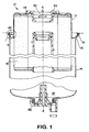
- Figure 1 is a sectional view through an exemplary filter cartridge 10 comprising a first housing section 12 joined to a second housing section 14 along a peripheral roll seam 16.
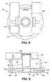
- Figure 4 illustrates an enlarged sectional view through the roll seam 16 on the left hand side of Figure 1 .
- the sheet metal of the respective housing sections which forms the roll seam is shown as dotted lines to the left and right of the filter cartridge 10 adjacent the roll seam in Figure 1 .
- the sheet metal extending from the housing first section 12 extends radially beyond the sheet metal of extending from the housing second section 14.
- the extended radial length of the sheet metal of the housing first section 12 is rolled under and overlaps the sheet metal of the housing second section 14.
- the rolled, overlapping sheet metal is then crimped to form the roll seam in a manner known in the art.
- a U-shaped bend in the housing first section 12 inwardly of the roll seam defines a space 20 between the roll seam and the housing first section 12. This space 20 allows access to the interior of the roll seam 16 during seam formation and for the purposes of deformation as will be discussed below.
- the filter cartridge 10 has an overall general configuration and functionality that is well understood by those of skill in the art.
- a filter element 18 is supported within the filter cartridge.
- a grommet 30 surrounds an axial opening 32 in the housing first section 12 that receives coaxial conduits (not shown) for delivery of unfiltered fluid and retrieval of filtered fluid from the filter cartridge 10.
- the housing second section 14 may be provided with a drain cock 60 for removal of water that may accumulate in a sump 15 defined by the lower portion of the housing second section 14.
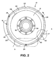
- FIG 2 is a top view of the filter cartridge of Figure 1 .
- the roll seam 16 circumscribes the filter cartridge 10 radially separated from the housing first section 12 to define an annular space 20.
- the roll seam 16 includes three portions that are radially outwardly displaced relative to the central axis A of the cartridge to form retention tabs 24.
- the retention tabs 24 are illustrated as being equiangularly arranged on the circumference of the roll seam and of equal angular extent and radial displacement.
- Three roll seam portions 23 extend between the retention tabs 24.
- each of these portions 23 of the roll seam include a radially inwardly displaced segment 22.
- the inwardly displaced segments 22 provide one variable for use in conjunction with a cartridge compatibility matrix.
- the inwardly displaced segments 22 of the roll seam 16 on the exemplary filter cartridge 10 are diametrically opposed to each retention tab 24.
- inward and outward displacement of the roll seam relative to its generally circular shape result in a serpentine configuration.
- This complex shape is advantageously located at the radial outer periphery of the filter cartridge.
- a compatibility matrix including a serpentine, or convoluted outer periphery of the filter cartridge presents unique opportunities for blocking reception of cartridges omitting portions of the compatibility matrix.
- inward and outward displacement of the roll seam 16 relative to the central axis A of the cartridge defines an annular space 20 having a variable radial dimension when measured perpendicular to the cartridge axis A, as best seen in Figure 2 .
- the shape of the annular space 20 may be used as part of a cartridge compatibility matrix when the cartridge 10 is mounted to a base including the component shown in Figures 12 and 13 by the collar shown in Figures 14 and 15 .
- the outer profile of the roll seam 16 is used as a constituent of a cartridge compatibility matrix when the cartridge 10 is mounted to a base including the component shown in Figures 6-11 .
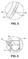
- Figure 3 illustrates an enlarged view of an inwardly displaced segment 22 of the roll seam 16.
- the inward displacement of the roll seam is in the form of an arc having a radius of curvature of approximately 2.5" (6.35cm) and a center of curvature located outside the roll seam 16.
- the inward deformation displaces the roll seam 16 inwardly from its normal radius of curvature 17 (illustrated by the dashed line in Figure 3 ) by a distance in the range of .02" (.05cm) to .05" (.127cm) at the center of the deformation.
- the inwardly displaced segment has a length of approximately .5" (1.27cm) measured along the circumference of the roll seam.
- FIG 5 is an enlarged portion of Figure 2 illustrating the outward displacement of the roll seam 16 to form a retention tab 24.
- the roll seam is radially outwardly displaced by a distance of approximately .08" (.2cm) relative to adjacent portions of the roll seam or a distance approximately equivalent to the radial thickness of the roll seam 16.
- Each retention tab 24 of the illustrated embodiment maintains its maximum outward displacement (of approximately one roll seam thickness) for approximately .5" (1.27cm).
- the roll seam 16 includes transitional portions 24a adjacent either end of the retention tabs.
- the roll seam 16 between the retention tabs 24 (including their transitional portions 24a) and the inwardly displaced segments 22 maintain a substantially constant radius of curvature centered on the cartridge axis A.
- FIGs 6 - 11 illustrate one component of a first embodiment of a filter base configured to mount the filter illustrated in Figures 1 - 5 .
- the illustrated component 40 of a filter base is a molded member with integrally extending bracket portions 42.
- the bracket portions 42 are configured to receive a reinforcing metal sleeve (not shown) through which an attachment bolt (not shown) retains the filter base to a support structure (not shown).
- the illustrated base component 40 comprises a generally cylindrical wall 46 that defines a receptacle 47 for axially receiving the filter cartridge housing first section 12.
- An axial central conduit 48 of the base component 40 is received and sealingly engaged by a grommet 30 of an installed filter cartridge 10.
- the cylindrical wall 46 flares to include a fixed integral retainer 44.
- the retainer 44 comprises three axial slots 51 complementary to the radially projecting retention tabs 24 on the cartridge 10.
- the axial slots 51 communicate with retaining channel portions 43 partially defined by a retaining lip upper surface comprising a ramp 52 and
- the first housing section 12 of the filter cartridge 10 is axially inserted into the receptacle 47 until the retaining tabs 24 are aligned with the retaining channel portions 49.
- the cartridge 10 is then rotated clockwise relative to the base. During rotation, the retaining tabs ride up the ramps 52 and over a raised portion of the retaining lip to seats 54 defined by the retaining lip upper surface.
- a resilient radial extension 34 of the cartridge grommet 30 biases the cartridge 10 away from the base component 40 so that the seated retention tabs 24 resist unintended counterclockwise rotation of the cartridge 10 relative to the base.
- the retainer 44 defines lip portions 72 having an inward-facing profile including radially inward projecting protrusions 56 corresponding to the location of each inwardly displaced segment 22 of the roll seam 16 relative to the retention tabs 24 (the location of which correspond to the axial slots 51 separating the retaining lip portions 72).
- the axial slots 51 and lip portions 72 with protrusions 56 code the base component 40 for a filter cartridge such as cartridge 10 with a roll seam having a compatible pattern of retention tabs 24 and inwardly displaced segments 22.
- the roll seam 16 of a compatible filter cartridge can pass the retaining lip portions 72, permitting complete axial reception of the cartridge housing first section 12 into the receptacle 47 so that subsequent rotation of the cartridge mounts the cartridge to the base.
- An incompatible cartridge (lacking, for example, the requisite inwardly displaced segments 22) is blocked from axial reception and cannot be mounted to the coded base.
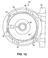
- FIGs 12 and 13 illustrate a second representative embodiment of a base component 80 configured to receive a cartridge illustrated in Figures 1 - 5 .
- This form of filter base comprises a cast or molded component 80 with a cylindrical wall 92 defining a receptacle 87 into which the housing first section 12 of the cartridge is axially receivable.
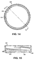
- the cartridge is retained to the base by a collar 100 (illustrated in Figures 14 and 15 ) that engages the peripheral roll seam 16.
- the end 82 of the wall 92 is provided with a sectional configuration complementary to the annular space 20 defined between the cartridge housing first section 12 and the roll seam 16.
- Radial outward projections 84 of the lip correspond to the location and outward radial displacement of the retention tabs 24.
- the base component 80 may be cast with the lip 82 having locations 86 where the lip is thinned or notched to accommodate inwardly displaced segments 22 of the cartridge roll seam 16.
- lip material may be removed after production of the base component 80, such as by machining the lip at locations 86.
- the collar 100 includes an inward projecting thread 108 configured to engage an outward projecting thread 88 on the base component 80. Rotation of the collar 100 relative to the base component 80 causes the collar thread 108 to ride the base thread 88, bringing the collar retaining lip 102 to bear against the radially projecting roll seam 16 of the cartridge 10.
- a spring (not shown) in the base receptacle 87 biases the cartridge 10 and collar 100 away from the base component to maintain the collar in a locked position over the end of the base thread 88.
- This mounting system requires that the axially projecting lip 82 of the base component be received in the annular space 20 with room for axial movement to accommodate compression and release of the spring as the collar thread 108 rides up and over the thread 88 of the base.
- a rigid abutment of the cartridge roll seam 16 against the lip 82 of the base that prevents the necessary axial movement of the cartridge 10 relative to the base component 80 will prevent complete rotation of the collar 100 to its locked position.
- the lip 102 of the collar 100 includes a plurality of locations 103 where the lip and adjacent structure is recessed or lip material is removed to accommodate the shape 13 (an outward deflection best seen in Figure 1 ) of the cartridge housing second section 14 adjacent the outward deformation of the roll seam 16 for each retention tab 24.
- the collar is provided with six locations 103 where lip material is removed.
- the six locations 103 correspond to the six possible engaged positions of the collar 100 relative to the base component 80 and the received filter cartridge 10.
- the outward deflections of the housing second section fit into three of the six locations, further enhancing the security of the collar 100 in its locked position relative to the cartridge 10 and the base component 80 by resisting unintentional reverse rotation of the collar.
- a filter cartridge lacking outward deformations 24 of the roll seam 16 complementary to the outward projections 84 on the axially projecting lip 82 of the base component 80 will be blocked from axial reception and mating with the base.
- filter cartridges including inward deformations of the roll seam will be rejected by a base whose axially projecting lip 82 does not include locations 86 where lip material has been removed to accommodate them.
- axial reception and mating with the base it is meant that the grommet 30 carried by the housing first section 12 fully engages the axial conduit 88 of the base component and the lip 82 of the base is received in the annular space 20 of the cartridge with room to move axially during rotation of the collar 100 to its locked position.
- the configuration of the axially projecting lip 82 forms a component of a cartridge compatibility matrix that codes the base for a cartridge having a particular shape of annular space 20 (as defined by deformations 24, 22 of the roll seam).
- a further aspect of the present invention contemplates a filter cartridge compatibility matrix comprising the roll seam retention tabs 24 and inward displaced segments 22 as described above and further including radial protrusions 28 of the cartridge housing section first end 12.
- a ring (not shown) is keyed to the base component to define an entrance to the receptacle 47.
- the ring includes openings that allow axial passage of the radial protrusions 28 of the housing first section 12. Once the radial protrusions 28 are axially past the ring, the receptacle 47 of the base component 40 permits rotation of the cartridge relative to the base.
- Radial protrusions 28 of the housing first section 12 may be used as an additional component of the cartridge compatibility matrix. The radial protrusions may also be employed to ensure a particular installed orientation of the cartridge 10 relative to the base component 40.
- the inside surface of the wall 92 defining the receptacle 87 of the second embodiment of a filter base component 80 may include axial tracks (not shown) complementary to the pattern of radial protrusions from the cartridge housing first section 12.
- the tracks may be molded and/or machined on the inner surface of the receptacle of the base component 80.
- a filter cartridge including an incompatible pattern of radial protrusions will be blocked from axial reception into the receptacle 87.
- the configuration of the filter cartridge roll seam 16 and received housing first section 12 can be used to ensure filter compatibility and a particular installed configuration of the filter cartridge 10 relative to the base component 80.
Description
- This invention relates generally to fuel filters employed in connection with internal combustion engines. More particularly, the present invention relates to replaceable fuel filter cartridges for removing foreign particles and/or separating water from the fuel supply system of an internal combustion engine.
- Fuel filter systems to which the invention relates commonly employ a disposable filter cartridge that is replaced at pre-established intervals of filter usage. The replaceable cartridge is conventionally secured to a base that defines inlet and outlet connections between the cartridge and the fuel supply system. Numerous retention systems have been employed for securing the filter cartridge to the base and allowing removal of the cartridge for replacement purposes.
- In practice, filter cartridge requirements may vary depending upon: the type and make of the internal combustion engine; the specific application for which the engine is employed; the climate in which the engine is operated; and/or regional characteristics as to the quality of the fuel supply. Filter cartridges suitable for replacement in a particular filtration system, commonly vary as to capacity, fluid compatibility and filter media qualities.
- One of the recurring problems in assuring filtration system performance is encountered in connection with replacement of the filter cartridge. It is imperative that the replacement cartridge be compatible with the filtering requirements for the fuel system. It is common for filter cartridges to have a generally similar exterior configuration regardless of performance. As a result, a replacement filter cartridge may dimensionally conform to the base of a given fuel filter assembly, and not comply with the applicable specifications for the fuel system and thereby jeopardize the integrity of the fuel filtering system. Replacement with an incompatible filter cartridge can have very serious consequences for the operation of the internal combustion engine and may also be unnecessarily more expensive than less costly cartridges which are fully suitable. In practice, replacement cartridges may be so similar in overall configuration that the owner of the vehicle and/or the maintenance technician servicing the internal combustion engine may unknowingly jeopardize the integrity of the filtering system by replacement with a wholly unsuitable cartridge even though the unsuitable cartridge at least cursorily appears to be suitable. There are also, of course, instances where inferior or improper replacement filter cartridges are intentionally installed without the knowledge of the owner of the operator of the vehicle.
- For many applications, it is also desirable that a cartridge be mounted to the base at a specific angular orientation so that warnings, directions and markings affixed to the cartridge may be properly positioned to ensure visibility and maximize the chances of successful information dissemination. For other applications, it is desirable that the cartridge be locked in position relative to the base such that the cartridge may not rotate with relation to the base.
-
U.S. Patent No. 5,035,797 , which is assigned to the assignee of the present invention, discloses a fuel filter assembly in which a base mounts to the vehicle and a disposable filter cartridge is suspended from the base. The cartridge is retained to the base by a threaded collar that engages against a protruding roll seam structure at the periphery of the cartridge housing. The cartridge is replaced by loosening the threaded collar and dismounting the filter cartridge. A key system is disclosed in which keys axially project from the base through corresponding slots in the end cap of the filter cartridge housing. The dimensions and location of the axially projecting keys ensure compatibility by interfering with mounting and sealing of incompatible cartridges lacking the correct slot configuration. The keys interlock with the slots to mount the cartridge at a fixed angular relationship to the base. -
U.S. Patent No. 5,837,137 , which is assigned to the assignee of the present invention, discloses a similarly configured fuel filtration assembly (e.g., the cartridge is retained to the base by a threaded collar) incorporating an alternative location and key system. Protrusions from a receiving surface of the base are received in corresponding dimples in the opposing end surface of the cartridge to lock the cartridge at a fixed angular position relative to the base. The protrusions interfere with the mounting and sealing of a non-compatible cartridge having an incompatible pattern of dimples. - A further variation on ensuring compatibility in fuel filtration assemblies similar to those described above is disclosed in
U.S. Patent No. 5,766,463 , which is assigned to the assignee of the present invention. The disclosed fuel filter cartridge is formed from a pair of shell sections joined along a roll seam to form the retaining shoulder. The generally cylindrical upper portion of the filter cartridge is received within the base. A plurality of arcuate protrusions radially project from the cylindrical upper portion of the cartridge to be received in compatible tracks in the base. The protrusions are disclosed as part of a key code system including the key/slot system described in the '797 patent. A keying system that relies on protrusions from the received portion of the cartridge housing may permit defeat of the keying system by allowing a cartridge without the protrusions to be received in the keyed base without interference. - An alternative filter cartridge mounting system is disclosed in
U.S. Patent No. 6,187,188 , also assigned to the assignee of the present invention. The roll seam at the junction of the cartridge housing sections is radially outwardly displaced to form a plurality of retention tabs. The base includes a fixed retaining structure comprising a retaining lip defining a plurality of axial slots in communication with retaining channel portions above the retaining lip. The axial slots are located and dimensioned to be complementary to the retaining tabs of the filter cartridge. The filter cartridge is retained to the base by axially aligning the tabs with the slots and upwardly displacing the cartridge into the receptacle of the base. The cartridge is then rotated so that the tabs are engaged within the retaining channel portions. The '188 patent discloses that compatibility of the cartridge with the base may be ensured by providing the received portion of the cartridge with arcuate slots to accommodate keys axially projecting from the base as disclosed in the '797 patent. Alternatively, the received portion of the cartridge may be provided with radial protrusions such as those disclosed in the '463 patent. Tracks in the base for receiving the protrusions must be L-shaped (have an axial portion and a radial portion) to accommodate rotation of the cartridge relative to the base. - Ensuring filter cartridge compatibility is an issue of continuing concern in the art. While the approaches to ensuring filter cartridge compatibility described in the '797, '137, '463, and '188 patents represent significant advances over the prior art, further improvements in effectiveness and efficiency are possible. For example, keys projecting from the base that require openings in the filter cartridge compromise the sealed integrity of the filtration system. Keying arrangements that restrict the cartridge to a fixed angular position relative to the base are incompatible with filter assemblies that require rotation of the cartridge relative to the base. The L-shaped tracks disclosed in the '188 patent may be difficult to produce, thereby increasing the cost of filter assemblies.
- There is an ongoing need in the art for a filter assembly that prevents installation of incompatible filter cartridges. Ideally, a filter cartridge compatible with such a key system may be employed with a filter assembly in which the cartridge is retained to the base by a collar and filter assemblies in which the cartridge is rotated to engage radially projecting tabs in a retainer fixedly extending from the base.
- A first aspect of the present invention pertains to inward and outward displacement of a roll seam at the junction of housing sections of a filter cartridge to provide components of a cartridge compatibility matrix. Portions of the roll seam are radially outwardly offset to form retention tabs. Further portions of the roll seam are radially inwardly displaced relative to the remainder of the roll seam. In one embodiment, the cartridge housing is substantially symmetric about a central axis, and the retention tabs are equiangularly spaced about the axis. The tabs are also substantially equivalent in angular extent and radial displacement, i.e., the tabs have the same general configuration. Consequently, the roll seam includes three substantially equal length portions extending between the retention tabs. One or more of these roll seam portions may include a segment that is inwardly displaced with respect to the central axis. The receptacle of a compatible base is provided with structures permitting reception and sealing of a cartridge with a complementary pattern of retention tabs and inward displaced segments. A non-compatible cartridge, for example a cartridge with a similar arrangement of retention tabs but lacking the requisite inwardly displaced segments of the roll seam, is prevented from mating with the base.
- In a base with a fixed retainer where the retention tabs are axially received through slots and the cartridge secured to the base by rotation relative to the base, compatibility is ensured by inward protrusions on the retainer lip. The inward protrusions of the retaining lip correspond to the inwardly displaced segments of the roll seam and allow axial reception of the roll seam through the retaining lip. The roll seam of an incompatible filter cartridge will lack the correct arrangement of inwardly displaced portions of the roll seam will be prevented from axial reception into the base. In one cartridge compatibility matrix, the roll seam includes three equiangularly spaced retention tabs and three equiangularly spaced inwardly displaced segments of the roll seam. Alternatively, the inwardly displaced portions may be non-symmetrical to ensure a particular installed orientation of the cartridge relative to the base.
- In addition, the filter cartridge may also comprise at least one outward protrusion from the side wall of that portion of the cartridge received in the base. Rather than an L shaped track in the base receptacle, a ring at the entrance to the receptacle defines axial openings compatible with the protrusions on the cartridge. Together, the configuration of the roll seam and the received portion of the cartridge may be incorporated into multiple levels of keying for cartridge identification, cartridge positioning and quality control purposes.
- Another aspect of the present invention relates to a filter assembly where a cartridge of the present invention is retained to a base by a collar. An annular lip of the base axially protrudes into a space defined between the roll seam and the received portion of the filter cartridge. The configuration of this space is complementary with the configuration of the roll seam, e.g., the retention tabs increase the radial dimension of the space and the inwardly displaced segments of the roll seam decrease the radial dimension of the space. The axially protruding lip of the base is provided with outward protrusions complementary with the retention tabs and locations where lip material is removed to accommodate inwardly displaced segments of the roll seam.
- An object of the present invention is to provide a new and improved filter cartridge compatibility matrix.
- Another object of the present invention is to provide a new and improved filter cartridge structure that ensures compatibility in filter assemblies having fixed and movable cartridge-retention systems.
- A further object of the present invention is to provide a new and improved filter assembly in which compatibility protection cannot be defeated by omission of the compatibility matrix structure from the cartridge.
- Other objects and advantages of the invention will become apparent from the drawings and the specification.
- The present invention may be better understood and its numerous objects and advantages will become apparent to those skilled in the art by reference to the accompanying drawings in which:
-
Figure 1 is a vertical sectional view, partly broken away, of a fuel filter cartridge incorporating a compatibility matrix exemplary of several aspects of the present invention; -
Figure 2 is a top plan view of the filter cartridge ofFigure 1 ; -
Figure 3 is an enlarged view of an inwardly displaced segment of the roll seam of the filter cartridge ofFigure 2 ; -
Figure 4 is an enlarged sectional view through the roll seam at the left side of the filter cartridge ofFigure 1 ; -
Figure 5 is an enlarged portion of the filter cartridge shown inFigure 2 illustrating a retention tab formed from an outward deformation of the roll seam; -
Figure 6 is a front view of a portion of a first filter base component configured to receive the filter cartridge ofFigure 1 ; -
Figure 7 is a side view of the filter base component ofFigure 6 ; -
Figure 8 is a top view of the filter base component ofFigure 6 ; -
Figure 9 is a sectional view of the filter base component ofFigure 6 , taken along line 9-9 thereof; -
Figure 10 is a bottom view, partly in phantom, of the filter base component ofFigure 6 ; -
Figure 11 is a sectional view of the filter base component ofFigure 6 , taken along line 11-11 thereof; -
Figure 12 is a side view of a second filter base component configured to receive the filter cartridge ofFigure 1 ; -
Figure 13 is a bottom view of the filter base component ofFigure 12 ; -
Figure 14 is bottom view, partly in phantom, of a retaining collar for retaining the filter cartridge ofFigure 1 to the base component ofFigures 12 and13 ; and -
Figure 15 is a sectional view of the collar ofFigure 14 , taken along line 15-15 thereof. - Preferred embodiments of a filter cartridge illustrating several aspects of the present invention will now be described with particular reference to
Figures 1 - 5 . A first embodiment of a filter base component compatible with the cartridge ofFigures 1-5 is shown inFigures 6 - 11 . A second embodiment of a filter base component compatible with the cartridge ofFigures 1-5 is shown inFigures 12 - 15 . -
Figure 1 is a sectional view through anexemplary filter cartridge 10 comprising afirst housing section 12 joined to asecond housing section 14 along aperipheral roll seam 16.Figure 4 illustrates an enlarged sectional view through theroll seam 16 on the left hand side ofFigure 1 . The sheet metal of the respective housing sections which forms the roll seam is shown as dotted lines to the left and right of thefilter cartridge 10 adjacent the roll seam inFigure 1 . The sheet metal extending from the housingfirst section 12 extends radially beyond the sheet metal of extending from the housingsecond section 14. When rolled together to form the roll seam shown inFigure 4 , the extended radial length of the sheet metal of the housingfirst section 12 is rolled under and overlaps the sheet metal of the housingsecond section 14. The rolled, overlapping sheet metal is then crimped to form the roll seam in a manner known in the art. A U-shaped bend in the housingfirst section 12 inwardly of the roll seam defines aspace 20 between the roll seam and the housingfirst section 12. Thisspace 20 allows access to the interior of theroll seam 16 during seam formation and for the purposes of deformation as will be discussed below. - The
filter cartridge 10 has an overall general configuration and functionality that is well understood by those of skill in the art. Afilter element 18 is supported within the filter cartridge. Agrommet 30 surrounds anaxial opening 32 in the housingfirst section 12 that receives coaxial conduits (not shown) for delivery of unfiltered fluid and retrieval of filtered fluid from thefilter cartridge 10. The housingsecond section 14 may be provided with adrain cock 60 for removal of water that may accumulate in asump 15 defined by the lower portion of the housingsecond section 14. -
Figure 2 is a top view of the filter cartridge ofFigure 1 . Theroll seam 16 circumscribes thefilter cartridge 10 radially separated from the housingfirst section 12 to define anannular space 20. Theroll seam 16 includes three portions that are radially outwardly displaced relative to the central axis A of the cartridge to formretention tabs 24. Theretention tabs 24 are illustrated as being equiangularly arranged on the circumference of the roll seam and of equal angular extent and radial displacement. Threeroll seam portions 23 extend between theretention tabs 24. In the illustrated embodiment, each of theseportions 23 of the roll seam include a radially inwardly displacedsegment 22. The inwardly displacedsegments 22 provide one variable for use in conjunction with a cartridge compatibility matrix. The inwardly displacedsegments 22 of theroll seam 16 on theexemplary filter cartridge 10 are diametrically opposed to eachretention tab 24. - The inward and outward displacement of the roll seam relative to its generally circular shape result in a serpentine configuration. This complex shape is advantageously located at the radial outer periphery of the filter cartridge. As will be discussed in greater detail below, a compatibility matrix including a serpentine, or convoluted outer periphery of the filter cartridge presents unique opportunities for blocking reception of cartridges omitting portions of the compatibility matrix. Further, inward and outward displacement of the
roll seam 16 relative to the central axis A of the cartridge defines anannular space 20 having a variable radial dimension when measured perpendicular to the cartridge axis A, as best seen inFigure 2 . The shape of theannular space 20 may be used as part of a cartridge compatibility matrix when thecartridge 10 is mounted to a base including the component shown inFigures 12 and13 by the collar shown inFigures 14 and 15 . In accordance with a further aspect of the present invention, the outer profile of theroll seam 16 is used as a constituent of a cartridge compatibility matrix when thecartridge 10 is mounted to a base including the component shown inFigures 6-11 . -
Figure 3 illustrates an enlarged view of an inwardly displacedsegment 22 of theroll seam 16. In the illustrated embodiment, the inward displacement of the roll seam is in the form of an arc having a radius of curvature of approximately 2.5" (6.35cm) and a center of curvature located outside theroll seam 16. The inward deformation displaces theroll seam 16 inwardly from its normal radius of curvature 17 (illustrated by the dashed line inFigure 3 ) by a distance in the range of .02" (.05cm) to .05" (.127cm) at the center of the deformation. The inwardly displaced segment has a length of approximately .5" (1.27cm) measured along the circumference of the roll seam. -
Figure 5 is an enlarged portion ofFigure 2 illustrating the outward displacement of theroll seam 16 to form aretention tab 24. The roll seam is radially outwardly displaced by a distance of approximately .08" (.2cm) relative to adjacent portions of the roll seam or a distance approximately equivalent to the radial thickness of theroll seam 16. Eachretention tab 24 of the illustrated embodiment maintains its maximum outward displacement (of approximately one roll seam thickness) for approximately .5" (1.27cm). It will be appreciated that theroll seam 16 includestransitional portions 24a adjacent either end of the retention tabs. Theroll seam 16 between the retention tabs 24 (including theirtransitional portions 24a) and the inwardly displacedsegments 22 maintain a substantially constant radius of curvature centered on the cartridge axis A. -
Figures 6 - 11 illustrate one component of a first embodiment of a filter base configured to mount the filter illustrated inFigures 1 - 5 . The illustratedcomponent 40 of a filter base is a molded member with integrally extendingbracket portions 42. Thebracket portions 42 are configured to receive a reinforcing metal sleeve (not shown) through which an attachment bolt (not shown) retains the filter base to a support structure (not shown). Below the bracket portions, the illustratedbase component 40 comprises a generallycylindrical wall 46 that defines areceptacle 47 for axially receiving the filter cartridge housingfirst section 12. An axialcentral conduit 48 of thebase component 40 is received and sealingly engaged by agrommet 30 of an installedfilter cartridge 10. Thecylindrical wall 46 flares to include a fixedintegral retainer 44. Theretainer 44 comprises threeaxial slots 51 complementary to the radially projectingretention tabs 24 on thecartridge 10. Theaxial slots 51 communicate with retainingchannel portions 43 partially defined by a retaining lip upper surface comprising aramp 52 and aseat 54. - The
first housing section 12 of thefilter cartridge 10 is axially inserted into thereceptacle 47 until the retainingtabs 24 are aligned with the retainingchannel portions 49. Thecartridge 10 is then rotated clockwise relative to the base. During rotation, the retaining tabs ride up theramps 52 and over a raised portion of the retaining lip toseats 54 defined by the retaining lip upper surface. Aresilient radial extension 34 of thecartridge grommet 30 biases thecartridge 10 away from thebase component 40 so that the seatedretention tabs 24 resist unintended counterclockwise rotation of thecartridge 10 relative to the base. - In accordance with an aspect of the present invention, the
retainer 44 defines lip portions 72 having an inward-facing profile including radially inward projectingprotrusions 56 corresponding to the location of each inwardly displacedsegment 22 of theroll seam 16 relative to the retention tabs 24 (the location of which correspond to theaxial slots 51 separating the retaining lip portions 72). Theaxial slots 51 and lip portions 72 withprotrusions 56 code thebase component 40 for a filter cartridge such ascartridge 10 with a roll seam having a compatible pattern ofretention tabs 24 and inwardly displacedsegments 22. Theroll seam 16 of a compatible filter cartridge can pass the retaining lip portions 72, permitting complete axial reception of the cartridge housingfirst section 12 into thereceptacle 47 so that subsequent rotation of the cartridge mounts the cartridge to the base. An incompatible cartridge (lacking, for example, the requisite inwardly displaced segments 22) is blocked from axial reception and cannot be mounted to the coded base. -
Figures 12 and13 illustrate a second representative embodiment of abase component 80 configured to receive a cartridge illustrated inFigures 1 - 5 . This form of filter base comprises a cast or moldedcomponent 80 with acylindrical wall 92 defining areceptacle 87 into which the housingfirst section 12 of the cartridge is axially receivable. The cartridge is retained to the base by a collar 100 (illustrated inFigures 14 and 15 ) that engages theperipheral roll seam 16. In accordance with an aspect of the present invention, theend 82 of thewall 92 is provided with a sectional configuration complementary to theannular space 20 defined between the cartridge housingfirst section 12 and theroll seam 16. Radialoutward projections 84 of the lip correspond to the location and outward radial displacement of theretention tabs 24. Thebase component 80 may be cast with thelip 82 havinglocations 86 where the lip is thinned or notched to accommodate inwardly displacedsegments 22 of thecartridge roll seam 16. Alternatively, lip material may be removed after production of thebase component 80, such as by machining the lip atlocations 86. - The
collar 100 includes an inward projectingthread 108 configured to engage an outward projectingthread 88 on thebase component 80. Rotation of thecollar 100 relative to thebase component 80 causes thecollar thread 108 to ride thebase thread 88, bringing thecollar retaining lip 102 to bear against the radially projectingroll seam 16 of thecartridge 10. A spring (not shown) in thebase receptacle 87 biases thecartridge 10 andcollar 100 away from the base component to maintain the collar in a locked position over the end of thebase thread 88. This mounting system requires that theaxially projecting lip 82 of the base component be received in theannular space 20 with room for axial movement to accommodate compression and release of the spring as thecollar thread 108 rides up and over thethread 88 of the base. A rigid abutment of thecartridge roll seam 16 against thelip 82 of the base that prevents the necessary axial movement of thecartridge 10 relative to thebase component 80 will prevent complete rotation of thecollar 100 to its locked position. - The
lip 102 of thecollar 100 includes a plurality oflocations 103 where the lip and adjacent structure is recessed or lip material is removed to accommodate the shape 13 (an outward deflection best seen inFigure 1 ) of the cartridge housingsecond section 14 adjacent the outward deformation of theroll seam 16 for eachretention tab 24. In the illustrated embodiment, the collar is provided with sixlocations 103 where lip material is removed. The sixlocations 103 correspond to the six possible engaged positions of thecollar 100 relative to thebase component 80 and the receivedfilter cartridge 10. The outward deflections of the housing second section fit into three of the six locations, further enhancing the security of thecollar 100 in its locked position relative to thecartridge 10 and thebase component 80 by resisting unintentional reverse rotation of the collar. - A filter cartridge lacking
outward deformations 24 of theroll seam 16 complementary to theoutward projections 84 on theaxially projecting lip 82 of thebase component 80 will be blocked from axial reception and mating with the base. Similarly, filter cartridges including inward deformations of the roll seam will be rejected by a base whoseaxially projecting lip 82 does not includelocations 86 where lip material has been removed to accommodate them. By axial reception and mating with the base, it is meant that thegrommet 30 carried by the housingfirst section 12 fully engages theaxial conduit 88 of the base component and thelip 82 of the base is received in theannular space 20 of the cartridge with room to move axially during rotation of thecollar 100 to its locked position. Thus, the configuration of theaxially projecting lip 82 forms a component of a cartridge compatibility matrix that codes the base for a cartridge having a particular shape of annular space 20 (as defined bydeformations - A further aspect of the present invention contemplates a filter cartridge compatibility matrix comprising the roll
seam retention tabs 24 and inward displacedsegments 22 as described above and further includingradial protrusions 28 of the cartridge housing sectionfirst end 12. In the first embodiment of afilter base component 40, a ring (not shown) is keyed to the base component to define an entrance to thereceptacle 47. The ring includes openings that allow axial passage of theradial protrusions 28 of the housingfirst section 12. Once theradial protrusions 28 are axially past the ring, thereceptacle 47 of thebase component 40 permits rotation of the cartridge relative to the base.Radial protrusions 28 of the housingfirst section 12 may be used as an additional component of the cartridge compatibility matrix. The radial protrusions may also be employed to ensure a particular installed orientation of thecartridge 10 relative to thebase component 40. - The inside surface of the
wall 92 defining thereceptacle 87 of the second embodiment of afilter base component 80 may include axial tracks (not shown) complementary to the pattern of radial protrusions from the cartridge housingfirst section 12. The tracks may be molded and/or machined on the inner surface of the receptacle of thebase component 80. A filter cartridge including an incompatible pattern of radial protrusions will be blocked from axial reception into thereceptacle 87. In combination, the configuration of the filtercartridge roll seam 16 and received housingfirst section 12 can be used to ensure filter compatibility and a particular installed configuration of thefilter cartridge 10 relative to thebase component 80.
Claims (20)
- A filter cartridge comprising: a filter element (18) arranged around a central axis (A); anda. a housing for said filter element, said housing comprising first and second sections (12, 14) having respective first and second diameters relative to a central axis (A), said second diameter being greater than said first diameter, said first section (12) surrounding an axial end of the filter element (18) and defining an axial opening (32) and joined to said second section (14) along a radially projecting shoulder (16), and whereb. said shoulder (16) has a primarily circular outer profile, said primarily circular outer profile being interrupted by angularly spaced retention tabs (24) projecting radially outwardly relative to said primarily circular outer profile,characterized in that said shoulder comprises at least one shoulder segment (22) having a reduced-radial distance from the central axis relative to the primarily circular outer profile.
- The filter cartridge of claim 1, characterized in that said shoulder (16) comprises a roll seam formed at the junction of said first and second sections (12, 14).
- The filter cartridge of claim 1, characterized in that said first section (12) comprises an axially extending generally cylindrical wall and said shoulder (16) is radially spaced from said cylindrical wall to define a substantially annular space (20).
- The filter cartridge of claim 3, characterized in that said substantially annular space (20) comprises first, second and third portions having respective first, second and third radial dimensions, said first radial dimension corresponding to a first radial distance between the cylindrical wall and the primarily circular outer profile, said second radial dimension corresponding to a second radial distance between the cylindrical wall and each of the retention tabs (24) and said third radial dimension corresponding to a third radial distance between the cylindrical wall and the shoulder segments (22) having a reduced radial distance from the central axis relative to the primarily circular outer profile, said first radial distance being less than said second radial distance and greater than said third radial distance.
- The filter cartridge of claim 1, characterized by comprising three retention tabs (24) equiangularly arranged around a circumference of said shoulder (16).
- The filter cartridge of claim 1, characterized in that said at least one shoulder segment (22) is angularly spaced from said retention tabs (24).
- The filter cartridge of claim 1, characterized by comprising three retention tabs (24) equiangularly arranged around a circumference of said shoulder (16) and in that said at least one shoulder segment (22) comprises three shoulder segments (22), each of said three shoulder segments (22) being diametrically opposed to a retention tab (24) .
- The filter cartridge of claim 1, characterized in that said at least one shoulder segment (22) comprises an arc having a center of curvature outside said primarily circular outer profile.
- The filter cartridge of claim 1, characterized in that said at least one shoulder segment (22) comprises a substantially linear portion of said shoulder (16) between two angularly spaced points on said primarily circular outer profile.
- The filter cartridge of claim 2, characterized in that said primarily circular outer profile comprises arcuate radially inner segments (23) of said shoulder (16) and said at least one shoulder segment (22) comprises a substantially linear segment of said roll seam (16) between two angularly spaced points on said primarily circular outer profile within said arcuate radially inner segments (23) of said shoulder (26).
- The filter cartridge of claim 2, characterized in that said primarily circular outer profile comprises arcuate radially inner segments (23) of said shoulder (16) end said at least one shoulder segment (22) comprises a substantially arcuate inward deflection of said roll seam (16) between two angularly offset points on said primarily circular outer profile within said arcuate radially inner segments (23) of said shoulder (16).
- The filter cartridge of claim 1, characterized by comprising three retention tabs (24) and said at least one shoulder segment comprising three shoulder segments (22).
- The filter cartridge of claim 1, characterized in that the three retention tabs (24) have equivalent first arcuate extents and said three shoulder segments (22) have equivalent second arcuate extents, said first arcuate extents subtending a greater angle than said second arcuate extents.
- A method for manufacturing a filter cartridge (10) according to claim 1, characterized by comprising the steps of:forming a roll (16) seam at the junction of first and second cartridge housing portions (12, 14), said roll seam (16) having a substantially constant radius of curvature;displacing at least a first portion (24) of said roll seam (16) radially outwardly relative to said radius of curvature; anddisplacing at least a second portion (22) of said roll seam (16) radially inwardly relative to said radius of curvature.
- The method of claim 14, characterized in that said step of displacing at least a first portion (24) comprises displacing three first portions (24) of said roll seam (16) radially outwardly relative to said radius of curvature.
- The method of claim 15, characterized in that said three first portions (24) are equiangularly arranged around an axis of said filter cartridge (10) and have substantially equivalent arcuate extents.
- The method of claim 16, characterized in that said step of displacing at least a second portion (22) comprises displacing three second portions (22) of said roll seam (16) radially inwardly relative to said radius of curvature.
- The method of claim 17, characterized in that said three second portions (22) are equiangularly arranged around an axis (A) of said filter cartridge (10) and are of substantially equivalent configuration.
- The method of claim 14, characterized in that said step of displacing at least a first portion (24) comprises displacing said at least a first portion radially outwardly by a distance of approximately 0.2 cm (0.08") relative to a central axis (A) of said cartridge.
- The method of claim 14, characterized in that said step of displacing at least a second portion comprises displacing said at least a second portion radally inwardly by a distance in the range of 0,05 cm (0.02") to 0,13 cm (0.05") relative to a central axis (A) of said cartridge (10).
Applications Claiming Priority (3)
| Application Number | Priority Date | Filing Date | Title |
|---|---|---|---|
| US10/284,694 US6863811B2 (en) | 2002-10-31 | 2002-10-31 | Filter cartridge incorporating a peripheral compatibility matrix |
| US284694 | 2002-10-31 | ||
| PCT/US2003/033384 WO2004041404A1 (en) | 2002-10-31 | 2003-10-21 | Filter cartridge incorporating a peripheral compatibility matrix |
Publications (2)
| Publication Number | Publication Date |
|---|---|
| EP1565244A1 EP1565244A1 (en) | 2005-08-24 |
| EP1565244B1 true EP1565244B1 (en) | 2010-06-16 |
Family
ID=32174935
Family Applications (1)
| Application Number | Title | Priority Date | Filing Date |
|---|---|---|---|
| EP03773304A Expired - Lifetime EP1565244B1 (en) | 2002-10-31 | 2003-10-21 | Filter cartridge incorporating a peripheral compatibility matrix |
Country Status (8)
| Country | Link |
|---|---|
| US (1) | US6863811B2 (en) |
| EP (1) | EP1565244B1 (en) |
| CN (1) | CN100387324C (en) |
| AU (1) | AU2003279998A1 (en) |
| BR (1) | BR0315741B1 (en) |
| DE (1) | DE60333030D1 (en) |
| ES (1) | ES2347235T3 (en) |
| WO (1) | WO2004041404A1 (en) |
Families Citing this family (22)
| Publication number | Priority date | Publication date | Assignee | Title |
|---|---|---|---|---|
| US6881334B2 (en) * | 2002-10-31 | 2005-04-19 | Stanadyne Corporation | Eccentric interference retention system for a filter cartridge |
| US7704396B2 (en) * | 2003-12-15 | 2010-04-27 | Filtran Llc | Coaxial full-flow and bypass oil filter with spring/gasket arrangement |
| US7704397B2 (en) * | 2003-12-15 | 2010-04-27 | Filtran Llc | Coaxial full-flow and bypass oil filter having cap with blades |
| US20060226065A1 (en) * | 2003-12-15 | 2006-10-12 | Meddock Leroy J | Coaxial full-flow and bypass oil filter apparatus and method |
| US7090773B2 (en) * | 2003-12-15 | 2006-08-15 | Spx Corporation | Coaxial full-flow and bypass oil filter |
| US8613786B2 (en) * | 2004-12-29 | 2013-12-24 | Baldwin Filters, Inc. | Fluid filter |
| US7850755B2 (en) * | 2004-12-29 | 2010-12-14 | Baldwin Filters, Inc. | Filter with improved fatigue performance and torque transfer |
| DE602006021276D1 (en) * | 2005-02-22 | 2011-05-26 | Baldwin Filters Inc | FILTER DEVICE |
| US8057669B2 (en) | 2005-02-22 | 2011-11-15 | Baldwin Filters, Inc. | Filter element and filter assembly including locking mechanism |
| US8293103B2 (en) * | 2005-12-08 | 2012-10-23 | Donaldson Company, Inc. | Spin-on filter assembly and methods |
| CA2573465C (en) * | 2006-01-10 | 2014-11-18 | Moen Incorporated | Filter adaptor |
| US8147691B2 (en) * | 2007-09-21 | 2012-04-03 | Baldwin Filters, Inc. | Filter cartridge housing attachment systems |
| US8241493B2 (en) | 2008-06-16 | 2012-08-14 | Baldwin Filters, Inc. | Filter with ejection mechanism |
| US8815090B2 (en) * | 2008-06-16 | 2014-08-26 | Baldwin Filters, Inc. | Filter with water separation device |
| US8128819B2 (en) | 2008-06-16 | 2012-03-06 | Baldwin Filters Inc. | Fluid filter, fluid filter assembly, and mounting method |
| WO2010074676A1 (en) * | 2008-12-23 | 2010-07-01 | Stanadyne Corporation | Filter assembly |
| US20100155321A1 (en) * | 2008-12-23 | 2010-06-24 | Sasur Timothy M | Filter assembly |
| US8991619B2 (en) | 2012-03-26 | 2015-03-31 | Baldwin Filters, Inc. | Filter assembly with water evacuation and methods |
| WO2014107412A1 (en) | 2013-01-04 | 2014-07-10 | Baldwin Filters, Inc. | Three-part end cap and filter element including same |
| BR112017002618B1 (en) | 2014-08-08 | 2023-02-23 | Parker-Hannifin Corporation | FILTER CARTRIDGE |
| EP3519075A4 (en) | 2016-10-03 | 2020-05-27 | Parker-Hannifin Corporation | Filter element with torsion lock and assembly |
| CN110769913B (en) | 2017-05-31 | 2021-11-16 | 帕克-汉尼芬公司 | Filter element with twist lock and/or sliding piston, assembly and method |
Family Cites Families (6)
| Publication number | Priority date | Publication date | Assignee | Title |
|---|---|---|---|---|
| US3225929A (en) * | 1961-10-11 | 1965-12-28 | American Mach & Foundry | Closure means for filter containing pressure vessels |
| US5035797A (en) * | 1990-02-14 | 1991-07-30 | Stanadyne Automotive Corp. | Key system for filter assembly |
| US5203994A (en) * | 1991-08-16 | 1993-04-20 | Stanadyne Automotive Corp. | Fuel filter retention system |
| US5186829A (en) * | 1991-08-16 | 1993-02-16 | Stanadyne Automotive Corp. | Fuel filter key system |
| US5837137A (en) * | 1996-08-21 | 1998-11-17 | Stanadyne Automotive Corp. | Base/cartridge location and key system for fuel filter assembly |
| US6187188B1 (en) * | 1999-07-19 | 2001-02-13 | Stanadyne Automotive Corp. | Filter cartridge retention system |
-
2002
- 2002-10-31 US US10/284,694 patent/US6863811B2/en not_active Expired - Lifetime
-
2003
- 2003-10-21 ES ES03773304T patent/ES2347235T3/en not_active Expired - Lifetime
- 2003-10-21 DE DE60333030T patent/DE60333030D1/en not_active Expired - Lifetime
- 2003-10-21 AU AU2003279998A patent/AU2003279998A1/en not_active Abandoned
- 2003-10-21 EP EP03773304A patent/EP1565244B1/en not_active Expired - Lifetime
- 2003-10-21 CN CNB2003801026244A patent/CN100387324C/en not_active Expired - Lifetime
- 2003-10-21 BR BRPI0315741-5A patent/BR0315741B1/en active IP Right Grant
- 2003-10-21 WO PCT/US2003/033384 patent/WO2004041404A1/en not_active Application Discontinuation
Also Published As
| Publication number | Publication date |
|---|---|
| AU2003279998A1 (en) | 2004-06-07 |
| BR0315741A (en) | 2005-09-20 |
| DE60333030D1 (en) | 2010-07-29 |
| CN100387324C (en) | 2008-05-14 |
| US6863811B2 (en) | 2005-03-08 |
| US20040084363A1 (en) | 2004-05-06 |
| ES2347235T3 (en) | 2010-10-27 |
| CN1708342A (en) | 2005-12-14 |
| BR0315741B1 (en) | 2011-06-28 |
| WO2004041404A1 (en) | 2004-05-21 |
| EP1565244A1 (en) | 2005-08-24 |
Similar Documents
| Publication | Publication Date | Title |
|---|---|---|
| EP1565244B1 (en) | Filter cartridge incorporating a peripheral compatibility matrix | |
| EP1558356B1 (en) | Keyed connection between filter base and filter cartridge | |
| US6911143B2 (en) | Base receptacle for filter cartridge incorporating a peripheral compatibility matrix | |
| EP0826406B1 (en) | Base/cartridge location and key system for fuel filter assembly | |
| EP0532161B1 (en) | Fuel filter key system | |
| EP0826407B1 (en) | Filter assembly with conformal cartridge support structure | |
| EP1126159B1 (en) | Key system for ecological filter cartridge and element | |
| US6187188B1 (en) | Filter cartridge retention system | |
| EP3235553B1 (en) | Filter element | |
| US6881334B2 (en) | Eccentric interference retention system for a filter cartridge | |
| US8146751B2 (en) | Filter element with threaded top endplate | |
| CN114980993A (en) | Filter assembly comprising a filter cartridge and a filter body |
Legal Events
| Date | Code | Title | Description |
|---|---|---|---|
| PUAI | Public reference made under article 153(3) epc to a published international application that has entered the european phase |
Free format text: ORIGINAL CODE: 0009012 |
|
| 17P | Request for examination filed |
Effective date: 20050531 |
|
| AK | Designated contracting states |
Kind code of ref document: A1 Designated state(s): AT BE BG CH CY CZ DE DK EE ES FI FR GB GR HU IE IT LI LU MC NL PT RO SE SI SK TR |
|
| AX | Request for extension of the european patent |
Extension state: AL LT LV MK |
|
| DAX | Request for extension of the european patent (deleted) | ||
| RBV | Designated contracting states (corrected) |
Designated state(s): DE ES FR GB IT |
|
| 17Q | First examination report despatched |
Effective date: 20060510 |
|
| GRAP | Despatch of communication of intention to grant a patent |
Free format text: ORIGINAL CODE: EPIDOSNIGR1 |
|
| GRAS | Grant fee paid |
Free format text: ORIGINAL CODE: EPIDOSNIGR3 |
|
| GRAA | (expected) grant |
Free format text: ORIGINAL CODE: 0009210 |
|
| AK | Designated contracting states |
Kind code of ref document: B1 Designated state(s): DE ES FR GB IT |
|
| REF | Corresponds to: |
Ref document number: 60333030 Country of ref document: DE Date of ref document: 20100729 Kind code of ref document: P |
|
| REG | Reference to a national code |
Ref country code: ES Ref legal event code: FG2A Ref document number: 2347235 Country of ref document: ES Kind code of ref document: T3 |
|
| PLBE | No opposition filed within time limit |
Free format text: ORIGINAL CODE: 0009261 |
|
| STAA | Information on the status of an ep patent application or granted ep patent |
Free format text: STATUS: NO OPPOSITION FILED WITHIN TIME LIMIT |
|
| 26N | No opposition filed |
Effective date: 20110317 |
|
| REG | Reference to a national code |
Ref country code: DE Ref legal event code: R097 Ref document number: 60333030 Country of ref document: DE Effective date: 20110316 |
|
| REG | Reference to a national code |
Ref country code: GB Ref legal event code: 732E Free format text: REGISTERED BETWEEN 20140619 AND 20140625 |
|
| REG | Reference to a national code |
Ref country code: DE Ref legal event code: R082 Ref document number: 60333030 Country of ref document: DE Representative=s name: GLAWE DELFS MOLL PARTNERSCHAFT MBB VON PATENT-, DE |
|
| REG | Reference to a national code |
Ref country code: ES Ref legal event code: PC2A Owner name: CLARCOR ENGINE MOBILE SOLUTIONS, LLC Effective date: 20140917 |
|
| REG | Reference to a national code |
Ref country code: DE Ref legal event code: R081 Ref document number: 60333030 Country of ref document: DE Owner name: CLARCOR ENGINE MOBILE SOLUTIONS, LLC (N. D. GE, US Free format text: FORMER OWNER: STANADYNE CORP., WINDSOR, CONN., US Effective date: 20140826 Ref country code: DE Ref legal event code: R082 Ref document number: 60333030 Country of ref document: DE Representative=s name: GLAWE DELFS MOLL PARTNERSCHAFT MBB VON PATENT-, DE Effective date: 20140826 |
|
| REG | Reference to a national code |
Ref country code: FR Ref legal event code: TP Owner name: CLARCOR ENGINE MOBILE SOLUTIONS, LLC, US Effective date: 20141210 |
|
| REG | Reference to a national code |
Ref country code: FR Ref legal event code: PLFP Year of fee payment: 13 |
|
| REG | Reference to a national code |
Ref country code: FR Ref legal event code: PLFP Year of fee payment: 14 |
|
| REG | Reference to a national code |
Ref country code: FR Ref legal event code: PLFP Year of fee payment: 15 |
|
| REG | Reference to a national code |
Ref country code: FR Ref legal event code: PLFP Year of fee payment: 16 |
|
| PGFP | Annual fee paid to national office [announced via postgrant information from national office to epo] |
Ref country code: FR Payment date: 20221025 Year of fee payment: 20 |
|
| PGFP | Annual fee paid to national office [announced via postgrant information from national office to epo] |
Ref country code: IT Payment date: 20221020 Year of fee payment: 20 Ref country code: GB Payment date: 20221027 Year of fee payment: 20 Ref country code: ES Payment date: 20221102 Year of fee payment: 20 Ref country code: DE Payment date: 20221027 Year of fee payment: 20 |
|
| P01 | Opt-out of the competence of the unified patent court (upc) registered |
Effective date: 20230524 |
|
| REG | Reference to a national code |
Ref country code: DE Ref legal event code: R071 Ref document number: 60333030 Country of ref document: DE |
|
| REG | Reference to a national code |
Ref country code: ES Ref legal event code: FD2A Effective date: 20231027 |
|
| REG | Reference to a national code |
Ref country code: GB Ref legal event code: PE20 Expiry date: 20231020 |
|
| PG25 | Lapsed in a contracting state [announced via postgrant information from national office to epo] |
Ref country code: GB Free format text: LAPSE BECAUSE OF EXPIRATION OF PROTECTION Effective date: 20231020 |
|
| PG25 | Lapsed in a contracting state [announced via postgrant information from national office to epo] |
Ref country code: ES Free format text: LAPSE BECAUSE OF EXPIRATION OF PROTECTION Effective date: 20231022 |
|
| PG25 | Lapsed in a contracting state [announced via postgrant information from national office to epo] |
Ref country code: GB Free format text: LAPSE BECAUSE OF EXPIRATION OF PROTECTION Effective date: 20231020 Ref country code: ES Free format text: LAPSE BECAUSE OF EXPIRATION OF PROTECTION Effective date: 20231022 |