EP1565048B1 - Rack mounted equipment case - Google Patents
Rack mounted equipment case Download PDFInfo
- Publication number
- EP1565048B1 EP1565048B1 EP04250781A EP04250781A EP1565048B1 EP 1565048 B1 EP1565048 B1 EP 1565048B1 EP 04250781 A EP04250781 A EP 04250781A EP 04250781 A EP04250781 A EP 04250781A EP 1565048 B1 EP1565048 B1 EP 1565048B1
- Authority
- EP
- European Patent Office
- Prior art keywords
- case
- mounted equipment
- rack mounted
- connector panel
- lid
- Prior art date
- Legal status (The legal status is an assumption and is not a legal conclusion. Google has not performed a legal analysis and makes no representation as to the accuracy of the status listed.)
- Expired - Lifetime
Links
- 238000012423 maintenance Methods 0.000 abstract description 7
- 230000007613 environmental effect Effects 0.000 abstract description 4
- 230000035939 shock Effects 0.000 description 4
- 229910052782 aluminium Inorganic materials 0.000 description 2
- XAGFODPZIPBFFR-UHFFFAOYSA-N aluminium Chemical compound [Al] XAGFODPZIPBFFR-UHFFFAOYSA-N 0.000 description 2
- 238000001125 extrusion Methods 0.000 description 2
- 239000000463 material Substances 0.000 description 2
- 230000001681 protective effect Effects 0.000 description 2
- 239000004411 aluminium Substances 0.000 description 1
- 239000002131 composite material Substances 0.000 description 1
- 238000010276 construction Methods 0.000 description 1
- 229910000078 germane Inorganic materials 0.000 description 1
- 238000007689 inspection Methods 0.000 description 1
- 238000004519 manufacturing process Methods 0.000 description 1
- 229910052751 metal Inorganic materials 0.000 description 1
- 239000002184 metal Substances 0.000 description 1
- 238000000034 method Methods 0.000 description 1
- 229920003023 plastic Polymers 0.000 description 1
- 239000004033 plastic Substances 0.000 description 1
- 238000007789 sealing Methods 0.000 description 1
- 238000009423 ventilation Methods 0.000 description 1
Images


Classifications
-
- H—ELECTRICITY
- H05—ELECTRIC TECHNIQUES NOT OTHERWISE PROVIDED FOR
- H05K—PRINTED CIRCUITS; CASINGS OR CONSTRUCTIONAL DETAILS OF ELECTRIC APPARATUS; MANUFACTURE OF ASSEMBLAGES OF ELECTRICAL COMPONENTS
- H05K5/00—Casings, cabinets or drawers for electric apparatus
- H05K5/0021—Side-by-side or stacked arrangements
Definitions
- the invention disclosed here relates to a case for rack mounted equipment.
- Rack mounted equipment cases are typically made from aluminium but may be made from other materials. They usually have a body tube that has a rectangular cross section closed at each end by removable covers. This shape makes them amenable to stacking in racks or stacking one on top of another. While these cases have many applications and uses, it is not uncommon to use them as transportable, protective housings for electronic components in harsh environmental conditions where the components are subjected to strong mechanical shocks, vibration or inclement weather.
- rack mounted equipment cases are used to network electronics in one case with another or to a broader network.
- the rack mounted equipment case often has a connector panel from which various kinds of cable and other electrical connectors or fittings protrude.
- the connector panel is usually attached to the case by small bolts or screws in a manner so that it can be removed in order to access internal components.
- the connector fittings are also located on the panel, it is necessary to disconnect corresponding cables and wiring before the panel can be opened. What this means is that use of the electronics inside the case is either lost or shut down during a maintenance or other operation.
- the invention relates to rack mounted equipment cases that house electronic components for use in electronics, industrial, military or related applications where it is necessary to protect interior components from extreme environmental conditions, shock and vibration. It is normally necessary for the case to be sealed.
- the case must provide a high degree of shock protection and be suitable for allowing the use of the equipment during transport. If the electronics are operational while in the sealed and shielded environment of the case, access to the interior of the case is essential for maintenance, inspection or other purposes and it is not acceptable to disconnect connectors to enable such access.
- the connector panel also needs to be protected from knocks that may dislodge the connectors and for health and safety reasons to protect employees working in the vicinity.
- the invention disclosed and described here is an improved case for rack mounted equipment that provides a solution to the technical problems discussed above.
- it enables access to and maintenance of electronics within the case without necessarily shutting them down or disconnecting them from other components.
- a case that is constructed in accordance with the invention is also well-suited for stacking, because the connector fittings do not protrude outwardly relative to the outermost envelope occupied by the case when it sits in a rack or against a wall. There is normally a space and consequently weight saving.
- the rack case design disclosed here provides rapid and easy access to components inside the case for maintenance purposes.
- a case for rack mounted equipment comprising a body tube having two ends, a connector panel secured to the body tube at a first end, and a removable lid at at least one end, wherein a surface of the connector panel is recessed relative to an outer profile of the case to provide protection for the connector panel.
- the rack mounted equipment case has a reduced-height, removable lid on the first end, and the connector panel surface is recessed relative to the reduced-height lid.
- the connector panel surface is protected below the reduced-height lid and provides an area for permanent placement of cable connectors, switches and similar fittings.
- the reduced-height lid can be removed easily for allowing access to the interior of the case without disconnecting the fittings. Therefore, in some instances it is possible to undertake maintenance operations while interior electronic components continue to operate.
- the connector panel is secured inwardly of and closes the first end.
- Such a case could have just one removable lid or cover at the other end.
- Rack mounted equipment cases in accordance with the invention protect the cables and connectors and makes it much simpler to shield and seal the contents of the case when a cover or lid is not there. These case configurations save space and weight.
- the lids may be connected to the cases by a plurality of straps or latches. Depending on the size of the case, a pair of latches, one on each side, is used to connect the reduced-height lid to the case. Two or more pairs of latches may be used to connect the full-height lid on the other end of the case.
- each case preferably has a plurality of feet, located on a bottom panel of the body tube typically near a corner of the case.
- a plurality of feet locators are similarly positioned on a top panel of the body tube of the case. The feet and feet locators are shaped to nest with each other and are arranged in an identical pattern so that one case can be stacked on top of another in a stable manner.
- an equipment item of the rack mountable type comprising a tubular casing having a connector panel wherein a surface of the connector panel is recessed relative to an outer profile of the case.
- the equipment item may be fitted into a further case for rack mount equipment, to protect the equipment item.
- a rack mounted equipment case constructed in accordance with an exemplary embodiment of the invention.
- the case 10 can be made from aluminum, plastics, composites or other materials via a variety of manufacturing techniques.
- the size of the case 10 may vary depending on the intended application. However, these factors are not considered to be germane to the invention.
- the case 10 has a full-height, removable lid or cover 12 on one end of a body tube 16. On the other end, the case has a reduced-height, removable lid or cover 14.
- the reduced-height lid 14 is considered to be the "front" of the case, while the full-height lid 12 is the "back.” It will be appreciated that in reality the case can be used either way round.
- Both the front and back lids 14, 12 are connected to the body 16 of the case by a plurality of straps or latches.
- the front lid 14 is connected to the body 16 by a pair of latches 18, 20, one on each side of the case.
- the rear lid is connected by four latches 22, 24, 26, 28, one pair to a side.
- the latches are of conventional construction.
- There are other ways for implementing the connection of the lids 12, 14 to the case body 16 such as, for example, using thumbwheel screws or other quick release fittings that could be mounted in recesses in the lids. These screws would connect to threaded bores in the case body 16.
- alternative connections are not illustrated in the drawings.
- a connector panel surface 30 is positioned below and recessed inwardly relative to an outer profile of the case and of the front lid 14.
- the connector panel could be above the lid 14 or two connector panels may be provided both above and below the reduced-height lid.
- the connector panel surface 30 has a number of cable and electrical or other fittings 32, 34, 36. These fittings are conventional in nature and depend on the specific components inside the case.
- the electrical connections can remain in place as the front lid 14 is removed from the case, or the back lid 12, for that matter. As mentioned above, this enables maintenance or other kinds of work to be performed inside the case without necessarily shutting down operation of the components. Also, it is very easy to access the interior case because of the quick release mechanism provided by latches 18, 20 in the front, or 22, 24, 26, 28 in the back, depending on the situation.
- lid 12 has been shown as a full height lid it will be appreciated that the case may have a reduced height lid and one or two connector panels 30 at each end.
- the bottom surface 38 of the case 10 has four feet 40, 42, 44, 46, which are mounted to the case in a conventional manner.
- the top surface 48 of the case has a series of four foot locators 50, 52, 54, 56. As illustrated in the drawings, these items are located near the corners of the case's body 16.
- the foot locators 50, 52, 54, 56 are arranged in an identical pattern to the feet 40, 42, 44, 46.
- reference numeral 58 illustrates a cross-sectional view of a typical foot.
- Reference numeral 60 illustrates a cross-sectional view of a typical foot locator.
- a recessed or surface-mounted handle 62 can be connected to each side 64 of the case, in the manner shown in the drawings.
- the rack mounted equipment case 10 is of similar configuration to that described above and similar parts are identified by the same reference numerals with the addition of a prime symbol.
- a normal inner frame 70 is suspended inside a body tube 16' on shock mounts 72.
- the case has one removable cover 12 and at the other end a flanged extrusion 74 is secured or welded to an inner wall of the body tube 16 inboard of the first end.
- a connector panel (not shown) is secured to the extrusion 74 so that it is recessed relative to the outer profile of the case 10' inwardly of the end face of the body tube 16'.
- the cables and connectors pass through the connector panel as in the previous embodiment to the electronics mounted within.
- the connector panel closes the whole of the end.
- a further protective cover may be available for providing enhanced protection when the electronics are not in use.
- the connector panel provides for shielding and sealing of the contents when the cover is not there. This results in space and weight savings.
- case 10 could be constructed with ventilation cut-outs or pressure relief valves, depending on whether or not the case is designed to be air-tight. As mentioned above, dimensions can vary depending on the particular application.
Landscapes
- Engineering & Computer Science (AREA)
- Microelectronics & Electronic Packaging (AREA)
- Casings For Electric Apparatus (AREA)
- Purses, Travelling Bags, Baskets, Or Suitcases (AREA)
- Automatic Analysis And Handling Materials Therefor (AREA)
- Input Circuits Of Receivers And Coupling Of Receivers And Audio Equipment (AREA)
Abstract
Description
- The invention disclosed here relates to a case for rack mounted equipment.
- There is a type of metal case used in industrial applications that is called a rack mounted equipment case used for accommodating rack-mount electronics, which is made to standard or other sizes - typically 19 inch (approx 46cm) but clearly the cases can be designed for any size. Rack mounted equipment cases are typically made from aluminium but may be made from other materials. They usually have a body tube that has a rectangular cross section closed at each end by removable covers. This shape makes them amenable to stacking in racks or stacking one on top of another. While these cases have many applications and uses, it is not uncommon to use them as transportable, protective housings for electronic components in harsh environmental conditions where the components are subjected to strong mechanical shocks, vibration or inclement weather.
- In certain applications, rack mounted equipment cases are used to network electronics in one case with another or to a broader network. In these particular applications, the rack mounted equipment case often has a connector panel from which various kinds of cable and other electrical connectors or fittings protrude. The connector panel is usually attached to the case by small bolts or screws in a manner so that it can be removed in order to access internal components. However, since the connector fittings are also located on the panel, it is necessary to disconnect corresponding cables and wiring before the panel can be opened. What this means is that use of the electronics inside the case is either lost or shut down during a maintenance or other operation.
- The invention relates to rack mounted equipment cases that house electronic components for use in electronics, industrial, military or related applications where it is necessary to protect interior components from extreme environmental conditions, shock and vibration. It is normally necessary for the case to be sealed.
- It is also a problem to provide electromagnetic (EMI / RFI) shielding to protect the internal electronics in the case from being disrupted by external sources whilst protecting external electronics from being disrupted from the internal items.
- Because the cases may be used in vehicles, the case must provide a high degree of shock protection and be suitable for allowing the use of the equipment during transport. If the electronics are operational while in the sealed and shielded environment of the case, access to the interior of the case is essential for maintenance, inspection or other purposes and it is not acceptable to disconnect connectors to enable such access.
- The connector panel also needs to be protected from knocks that may dislodge the connectors and for health and safety reasons to protect employees working in the vicinity.
- In many applications the space and weight allowance available for the rack mounted equipment cases may be limited.
- The invention disclosed and described here is an improved case for rack mounted equipment that provides a solution to the technical problems discussed above. In particular it enables access to and maintenance of electronics within the case without necessarily shutting them down or disconnecting them from other components. A case that is constructed in accordance with the invention is also well-suited for stacking, because the connector fittings do not protrude outwardly relative to the outermost envelope occupied by the case when it sits in a rack or against a wall. There is normally a space and consequently weight saving. Finally, the rack case design disclosed here provides rapid and easy access to components inside the case for maintenance purposes.
- In accordance with the invention there is provided a case for rack mounted equipment comprising a body tube having two ends, a connector panel secured to the body tube at a first end, and a removable lid at at least one end, wherein a surface of the connector panel is recessed relative to an outer profile of the case to provide protection for the connector panel.
- Preferably the rack mounted equipment case has a reduced-height, removable lid on the first end, and the connector panel surface is recessed relative to the reduced-height lid.
- The connector panel surface is protected below the reduced-height lid and provides an area for permanent placement of cable connectors, switches and similar fittings.
- The reduced-height lid can be removed easily for allowing access to the interior of the case without disconnecting the fittings. Therefore, in some instances it is possible to undertake maintenance operations while interior electronic components continue to operate.
- In an alternative configuration, the connector panel is secured inwardly of and closes the first end. Such a case could have just one removable lid or cover at the other end.
- Rack mounted equipment cases in accordance with the invention protect the cables and connectors and makes it much simpler to shield and seal the contents of the case when a cover or lid is not there. These case configurations save space and weight.
- The lids may be connected to the cases by a plurality of straps or latches. Depending on the size of the case, a pair of latches, one on each side, is used to connect the reduced-height lid to the case. Two or more pairs of latches may be used to connect the full-height lid on the other end of the case.
- In order to facilitate stable stacking of one case on another, each case preferably has a plurality of feet, located on a bottom panel of the body tube typically near a corner of the case. A plurality of feet locators are similarly positioned on a top panel of the body tube of the case. The feet and feet locators are shaped to nest with each other and are arranged in an identical pattern so that one case can be stacked on top of another in a stable manner.
- In EP 1298973 there is disclosed an equipment item of the rack mountable type comprising a tubular casing having a connector panel wherein a surface of the connector panel is recessed relative to an outer profile of the case. The equipment item may be fitted into a further case for rack mount equipment, to protect the equipment item.
- These various features are described in greater detail below.
- In order that the invention may be well understood two embodiments thereof will now be described, by way of example only, with reference to the accompanying diagrammatic drawings. In the drawings, like reference numerals and letters refer to like parts throughout the various views, and wherein:
- Fig. 1 is a pictorial view of a rack mounted equipment case constructed in accordance with a first embodiment of the invention;
- Fig. 2 is a view like Fig. 1, but is taken from a position underneath the case;
- Fig. 3 is view like Fig. 1, but shows the reduced-height lid removed from the case;
- Fig. 4 is a view like Fig. 3, but is taken from below the case;
- Fig. 5 is another pictorial view that shows the full-height lid removed from the case;
- Fig. 6 is a view like Fig. 5, but is taken from below the case;
- Fig. 7 is a view of the reduced-height end of the case;
- Fig. 8 is a view of the full-height end of the case;
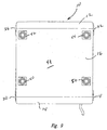
- Fig. 9 is a top view of the case;
- Fig. 10 is a bottom view of the case;
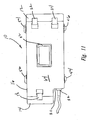
- Fig. 11 is a side view of the case;
- Fig. 12 illustrates a plurality of cases stacked one on top of another;
- Fig. 13 is a cross-sectional view showing a case foot about to be nested within a foot locator;
- Fig. 14 is a view like Fig. 13, but shows the foot nested within the foot locator; and
- Fig. 15 shows a perspective view of a second embodiment of a rack mounted equipment case.
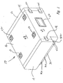
- Referring now to the drawings, and first to Fig. 1, shown generally at 10 is a rack mounted equipment case constructed in accordance with an exemplary embodiment of the invention. The
case 10 can be made from aluminum, plastics, composites or other materials via a variety of manufacturing techniques. The size of thecase 10 may vary depending on the intended application. However, these factors are not considered to be germane to the invention. - The
case 10 has a full-height, removable lid or cover 12 on one end of abody tube 16. On the other end, the case has a reduced-height, removable lid orcover 14. The reduced-height lid 14 is considered to be the "front" of the case, while the full-height lid 12 is the "back." It will be appreciated that in reality the case can be used either way round. - Both the front and
back lids body 16 of the case by a plurality of straps or latches. For example, referring to Fig. 3, thefront lid 14 is connected to thebody 16 by a pair oflatches latches lids case body 16 such as, for example, using thumbwheel screws or other quick release fittings that could be mounted in recesses in the lids. These screws would connect to threaded bores in thecase body 16. However, alternative connections are not illustrated in the drawings. - Directing attention again to Fig. 1, a
connector panel surface 30 is positioned below and recessed inwardly relative to an outer profile of the case and of thefront lid 14. The connector panel could be above thelid 14 or two connector panels may be provided both above and below the reduced-height lid. Theconnector panel surface 30 has a number of cable and electrical orother fittings case 10 is used to house electronics, the electrical connections can remain in place as thefront lid 14 is removed from the case, or theback lid 12, for that matter. As mentioned above, this enables maintenance or other kinds of work to be performed inside the case without necessarily shutting down operation of the components. Also, it is very easy to access the interior case because of the quick release mechanism provided bylatches - Although the
lid 12 has been shown as a full height lid it will be appreciated that the case may have a reduced height lid and one or twoconnector panels 30 at each end. - Referring to Fig. 2, the
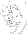
bottom surface 38 of thecase 10 has fourfeet top surface 48 of the case has a series of fourfoot locators body 16. - The
foot locators feet reference numeral 58 illustrates a cross-sectional view of a typical foot.Reference numeral 60 illustrates a cross-sectional view of a typical foot locator. When onecase 10 is stacked on top of another, thefoot 58 nests withinfoot locator 60 in the manner illustrated in Fig. 14. This enables the stacking arrangement illustrated in Fig. 12. In order to improve the ease of handling individual cases, a recessed or surface-mountedhandle 62 can be connected to eachside 64 of the case, in the manner shown in the drawings. - In a second embodiment as shown in Figure 15, the rack mounted
equipment case 10 is of similar configuration to that described above and similar parts are identified by the same reference numerals with the addition of a prime symbol. - A normal
inner frame 70 is suspended inside a body tube 16' on shock mounts 72. The case has oneremovable cover 12 and at the other end aflanged extrusion 74 is secured or welded to an inner wall of thebody tube 16 inboard of the first end. A connector panel (not shown) is secured to theextrusion 74 so that it is recessed relative to the outer profile of the case 10' inwardly of the end face of the body tube 16'. The cables and connectors pass through the connector panel as in the previous embodiment to the electronics mounted within. The connector panel closes the whole of the end. A further protective cover may be available for providing enhanced protection when the electronics are not in use. The connector panel provides for shielding and sealing of the contents when the cover is not there. This results in space and weight savings. - A case that is constructed in the above manner may be used for many different kinds of military or industrial applications and other uses where unusual environmental conditions come into play. While it is not shown in the drawings,
case 10 could be constructed with ventilation cut-outs or pressure relief valves, depending on whether or not the case is designed to be air-tight. As mentioned above, dimensions can vary depending on the particular application.
Claims (10)
- A case (10) for rack mounted equipment comprising a body tube (16) having two ends,
a connector panel (30) secured to the body tube (16) at a first end,
and characterised by:a removable lid (12,14) at at least one end;wherein a surface (30) of the connector panel is recessed relative to an outer profile of the case (10), to provide protection for the connector panel. - A case (10) for rack mounted equipment as claimed in claim 1, having a reduced-height, removable lid (14) on the first end, and the connector panel surface(30) is recessed relative to the reduced-height lid (14).
- A case (10) for rack mounted equipment as claimed in claim 2, wherein the connector panel surface (30) is positioned above or below the reduced-height lid (14).
- A case (10) for rack mounted equipment as claimed in claim 2 or 3, having a full-height, removable lid (12) on the other end.
- A case (10) for rack mounted equipment as claimed in any one of the preceding claims, wherein a second recessed connector panel surface is provided on the other end.
- A case (10) for rack mounted equipment as claimed in claim 1, wherein the connector panel (30') is secured inboard of and closes the first end.
- A case (10) for rack mounted equipment as claimed in claim 1, having a removable lid (14) on an end, and a connector panel on the same end that is recessed relative to the removable lid.
- A case (10) for rack mounted equipment as claimed in any one of the preceding claims wherein the or each connector panel surface (30) is permanently secured to the case.
- A case (10) for rack mounted equipment of claim 1, including a plurality of feet located on a bottom surface of the case, and a plurality of feet locators positioned on a top surface of the case, each foot being shaped to nest within a respective foot locator, the feet and feet locators being arranged in a substantially identical pattern to facilitate stable stacking of one equipment case on another.
- The case (10) for rack mounted equipment of claim 1, including a plurality of latches for removably connecting each lid to the case.
Priority Applications (3)
| Application Number | Priority Date | Filing Date | Title |
|---|---|---|---|
| DE602004005813T DE602004005813T2 (en) | 2004-02-13 | 2004-02-13 | Rack mounted device housing |
| EP04250781A EP1565048B1 (en) | 2004-02-13 | 2004-02-13 | Rack mounted equipment case |
| AT04250781T ATE359693T1 (en) | 2004-02-13 | 2004-02-13 | EQUIPMENT HOUSING MOUNTED IN A RACK |
Applications Claiming Priority (1)
| Application Number | Priority Date | Filing Date | Title |
|---|---|---|---|
| EP04250781A EP1565048B1 (en) | 2004-02-13 | 2004-02-13 | Rack mounted equipment case |
Publications (2)
| Publication Number | Publication Date |
|---|---|
| EP1565048A1 EP1565048A1 (en) | 2005-08-17 |
| EP1565048B1 true EP1565048B1 (en) | 2007-04-11 |
Family
ID=34684768
Family Applications (1)
| Application Number | Title | Priority Date | Filing Date |
|---|---|---|---|
| EP04250781A Expired - Lifetime EP1565048B1 (en) | 2004-02-13 | 2004-02-13 | Rack mounted equipment case |
Country Status (3)
| Country | Link |
|---|---|
| EP (1) | EP1565048B1 (en) |
| AT (1) | ATE359693T1 (en) |
| DE (1) | DE602004005813T2 (en) |
Families Citing this family (2)
| Publication number | Priority date | Publication date | Assignee | Title |
|---|---|---|---|---|
| DE102014218533A1 (en) | 2014-09-16 | 2016-03-17 | Robert Bosch Gmbh | Device arrangement with a 19-inch rack |
| CN114051336B (en) * | 2021-10-26 | 2023-09-22 | 重庆微思贝科技有限公司 | Layering type internet cabinet convenient for high-altitude overhaul |
Citations (2)
| Publication number | Priority date | Publication date | Assignee | Title |
|---|---|---|---|---|
| EP0965785A1 (en) * | 1998-06-18 | 1999-12-22 | Tektronix, Inc. | Instrument with multiple position support handle |
| EP1133221A1 (en) * | 1999-09-06 | 2001-09-12 | Sony Computer Entertainment Inc. | Electronic device and case |
Family Cites Families (4)
| Publication number | Priority date | Publication date | Assignee | Title |
|---|---|---|---|---|
| DE3624682A1 (en) * | 1986-07-22 | 1988-01-28 | Philips Patentverwaltung | Apparatus insert for telecommunications technology |
| DE3933643A1 (en) * | 1989-10-08 | 1991-04-11 | Asea Brown Boveri | Measuring appts. with modular measuring devices - has interchangeable measuring fitted to carrier plate for insertion in standard size rack |
| DE29606194U1 (en) * | 1996-04-04 | 1996-06-13 | Phoenix Contact Gmbh & Co | Junction box |
| US6720776B2 (en) * | 2001-09-28 | 2004-04-13 | Tektronix, Inc. | Instrument with housing having recess for connectors |
-
2004
- 2004-02-13 DE DE602004005813T patent/DE602004005813T2/en not_active Expired - Fee Related
- 2004-02-13 AT AT04250781T patent/ATE359693T1/en not_active IP Right Cessation
- 2004-02-13 EP EP04250781A patent/EP1565048B1/en not_active Expired - Lifetime
Patent Citations (2)
| Publication number | Priority date | Publication date | Assignee | Title |
|---|---|---|---|---|
| EP0965785A1 (en) * | 1998-06-18 | 1999-12-22 | Tektronix, Inc. | Instrument with multiple position support handle |
| EP1133221A1 (en) * | 1999-09-06 | 2001-09-12 | Sony Computer Entertainment Inc. | Electronic device and case |
Also Published As
| Publication number | Publication date |
|---|---|
| DE602004005813T2 (en) | 2008-01-10 |
| ATE359693T1 (en) | 2007-05-15 |
| EP1565048A1 (en) | 2005-08-17 |
| DE602004005813D1 (en) | 2007-05-24 |
Similar Documents
| Publication | Publication Date | Title |
|---|---|---|
| US6242691B1 (en) | Electronic packaging and method of packaging | |
| US7450382B1 (en) | Apparatus for enclosing electronic components | |
| US20100315788A1 (en) | Side-exhaust cooling system for rack mounted equipment | |
| US20090086420A1 (en) | Rugged conductive housing structure for portable computing device display | |
| US9371038B2 (en) | Removable payload containment systems for platforms, installation methods thereof, and payload integration kits for existing platforms | |
| CN101828231A (en) | Fire resistant enclosure for a data storage device having heat sink capabilities and method for making the same | |
| EP1565048B1 (en) | Rack mounted equipment case | |
| US6751096B2 (en) | Modular electronic housing | |
| US5375709A (en) | Printed circuit board carrier and reusable transport packaging | |
| US20050178680A1 (en) | Modular equipment case | |
| US7817420B2 (en) | Portable environmentally robust enclosure optimized for size, weight, and power dissipation | |
| GB2395069A (en) | Rack-mounted equipment case | |
| US6111192A (en) | Height reducible EMI shielded electronic enclosure | |
| CN105955417A (en) | Cabinet | |
| US20020070043A1 (en) | Casing used in outdoors | |
| US11855300B2 (en) | Electric vehicle battery pack having external side pouch for electrical components | |
| WO2017161191A1 (en) | Explosion proof enclosures | |
| AU2021273879B2 (en) | Computing device | |
| EP1150555A2 (en) | Housing for a frequency converter | |
| JP7102435B2 (en) | Housing for receiving electrical or electronic functional assemblies | |
| CN219554290U (en) | Novel explosion-proof case | |
| US11081867B2 (en) | Avionics power management panel and door assembly | |
| US7932466B2 (en) | Nautilus self pressurizing equipment enclosure | |
| WO2000047029A1 (en) | Electronic packaging system | |
| RU120310U1 (en) | MULTI-SECTION INSERT MODULE |
Legal Events
| Date | Code | Title | Description |
|---|---|---|---|
| PUAI | Public reference made under article 153(3) epc to a published international application that has entered the european phase |
Free format text: ORIGINAL CODE: 0009012 |
|
| AK | Designated contracting states |
Kind code of ref document: A1 Designated state(s): AT BE BG CH CY CZ DE DK EE ES FI FR GB GR HU IE IT LI LU MC NL PT RO SE SI SK TR |
|
| AX | Request for extension of the european patent |
Extension state: AL LT LV MK |
|
| 17P | Request for examination filed |
Effective date: 20051021 |
|
| AKX | Designation fees paid |
Designated state(s): AT BE BG CH CY CZ DE DK EE ES FI FR GB GR HU IE IT LI LU MC NL PT RO SE SI SK TR |
|
| GRAP | Despatch of communication of intention to grant a patent |
Free format text: ORIGINAL CODE: EPIDOSNIGR1 |
|
| GRAS | Grant fee paid |
Free format text: ORIGINAL CODE: EPIDOSNIGR3 |
|
| GRAA | (expected) grant |
Free format text: ORIGINAL CODE: 0009210 |
|
| AK | Designated contracting states |
Kind code of ref document: B1 Designated state(s): AT BE BG CH CY CZ DE DK EE ES FI FR GB GR HU IE IT LI LU MC NL PT RO SE SI SK TR |
|
| PG25 | Lapsed in a contracting state [announced via postgrant information from national office to epo] |
Ref country code: FI Free format text: LAPSE BECAUSE OF FAILURE TO SUBMIT A TRANSLATION OF THE DESCRIPTION OR TO PAY THE FEE WITHIN THE PRESCRIBED TIME-LIMIT Effective date: 20070411 Ref country code: SI Free format text: LAPSE BECAUSE OF FAILURE TO SUBMIT A TRANSLATION OF THE DESCRIPTION OR TO PAY THE FEE WITHIN THE PRESCRIBED TIME-LIMIT Effective date: 20070411 |
|
| REG | Reference to a national code |
Ref country code: GB Ref legal event code: FG4D |
|
| REG | Reference to a national code |
Ref country code: CH Ref legal event code: EP |
|
| REG | Reference to a national code |
Ref country code: IE Ref legal event code: FG4D |
|
| REF | Corresponds to: |
Ref document number: 602004005813 Country of ref document: DE Date of ref document: 20070524 Kind code of ref document: P |
|
| PG25 | Lapsed in a contracting state [announced via postgrant information from national office to epo] |
Ref country code: SE Free format text: LAPSE BECAUSE OF FAILURE TO SUBMIT A TRANSLATION OF THE DESCRIPTION OR TO PAY THE FEE WITHIN THE PRESCRIBED TIME-LIMIT Effective date: 20070711 |
|
| PG25 | Lapsed in a contracting state [announced via postgrant information from national office to epo] |
Ref country code: ES Free format text: LAPSE BECAUSE OF FAILURE TO SUBMIT A TRANSLATION OF THE DESCRIPTION OR TO PAY THE FEE WITHIN THE PRESCRIBED TIME-LIMIT Effective date: 20070722 |
|
| REG | Reference to a national code |
Ref country code: CH Ref legal event code: NV Representative=s name: KEMIA SA |
|
| PG25 | Lapsed in a contracting state [announced via postgrant information from national office to epo] |
Ref country code: PT Free format text: LAPSE BECAUSE OF FAILURE TO SUBMIT A TRANSLATION OF THE DESCRIPTION OR TO PAY THE FEE WITHIN THE PRESCRIBED TIME-LIMIT Effective date: 20070911 |
|
| NLV1 | Nl: lapsed or annulled due to failure to fulfill the requirements of art. 29p and 29m of the patents act | ||
| ET | Fr: translation filed | ||
| PG25 | Lapsed in a contracting state [announced via postgrant information from national office to epo] |
Ref country code: AT Free format text: LAPSE BECAUSE OF FAILURE TO SUBMIT A TRANSLATION OF THE DESCRIPTION OR TO PAY THE FEE WITHIN THE PRESCRIBED TIME-LIMIT Effective date: 20070411 |
|
| PG25 | Lapsed in a contracting state [announced via postgrant information from national office to epo] |
Ref country code: BE Free format text: LAPSE BECAUSE OF FAILURE TO SUBMIT A TRANSLATION OF THE DESCRIPTION OR TO PAY THE FEE WITHIN THE PRESCRIBED TIME-LIMIT Effective date: 20070411 |
|
| PG25 | Lapsed in a contracting state [announced via postgrant information from national office to epo] |
Ref country code: NL Free format text: LAPSE BECAUSE OF FAILURE TO SUBMIT A TRANSLATION OF THE DESCRIPTION OR TO PAY THE FEE WITHIN THE PRESCRIBED TIME-LIMIT Effective date: 20070411 Ref country code: BG Free format text: LAPSE BECAUSE OF FAILURE TO SUBMIT A TRANSLATION OF THE DESCRIPTION OR TO PAY THE FEE WITHIN THE PRESCRIBED TIME-LIMIT Effective date: 20070711 Ref country code: DK Free format text: LAPSE BECAUSE OF FAILURE TO SUBMIT A TRANSLATION OF THE DESCRIPTION OR TO PAY THE FEE WITHIN THE PRESCRIBED TIME-LIMIT Effective date: 20070411 Ref country code: CZ Free format text: LAPSE BECAUSE OF FAILURE TO SUBMIT A TRANSLATION OF THE DESCRIPTION OR TO PAY THE FEE WITHIN THE PRESCRIBED TIME-LIMIT Effective date: 20070411 |
|
| PLBE | No opposition filed within time limit |
Free format text: ORIGINAL CODE: 0009261 |
|
| STAA | Information on the status of an ep patent application or granted ep patent |
Free format text: STATUS: NO OPPOSITION FILED WITHIN TIME LIMIT |
|
| PG25 | Lapsed in a contracting state [announced via postgrant information from national office to epo] |
Ref country code: SK Free format text: LAPSE BECAUSE OF FAILURE TO SUBMIT A TRANSLATION OF THE DESCRIPTION OR TO PAY THE FEE WITHIN THE PRESCRIBED TIME-LIMIT Effective date: 20070411 |
|
| REG | Reference to a national code |
Ref country code: GB Ref legal event code: 732E |
|
| 26N | No opposition filed |
Effective date: 20080114 |
|
| PG25 | Lapsed in a contracting state [announced via postgrant information from national office to epo] |
Ref country code: GR Free format text: LAPSE BECAUSE OF FAILURE TO SUBMIT A TRANSLATION OF THE DESCRIPTION OR TO PAY THE FEE WITHIN THE PRESCRIBED TIME-LIMIT Effective date: 20070712 |
|
| PGFP | Annual fee paid to national office [announced via postgrant information from national office to epo] |
Ref country code: CH Payment date: 20080229 Year of fee payment: 5 |
|
| PG25 | Lapsed in a contracting state [announced via postgrant information from national office to epo] |
Ref country code: RO Free format text: LAPSE BECAUSE OF FAILURE TO SUBMIT A TRANSLATION OF THE DESCRIPTION OR TO PAY THE FEE WITHIN THE PRESCRIBED TIME-LIMIT Effective date: 20070411 |
|
| PGFP | Annual fee paid to national office [announced via postgrant information from national office to epo] |
Ref country code: DE Payment date: 20080214 Year of fee payment: 5 Ref country code: GB Payment date: 20080212 Year of fee payment: 5 Ref country code: IT Payment date: 20080226 Year of fee payment: 5 |
|
| PGFP | Annual fee paid to national office [announced via postgrant information from national office to epo] |
Ref country code: FR Payment date: 20080222 Year of fee payment: 5 |
|
| PG25 | Lapsed in a contracting state [announced via postgrant information from national office to epo] |
Ref country code: MC Free format text: LAPSE BECAUSE OF NON-PAYMENT OF DUE FEES Effective date: 20080228 |
|
| PG25 | Lapsed in a contracting state [announced via postgrant information from national office to epo] |
Ref country code: EE Free format text: LAPSE BECAUSE OF FAILURE TO SUBMIT A TRANSLATION OF THE DESCRIPTION OR TO PAY THE FEE WITHIN THE PRESCRIBED TIME-LIMIT Effective date: 20070411 Ref country code: IE Free format text: LAPSE BECAUSE OF NON-PAYMENT OF DUE FEES Effective date: 20080213 |
|
| PG25 | Lapsed in a contracting state [announced via postgrant information from national office to epo] |
Ref country code: CY Free format text: LAPSE BECAUSE OF FAILURE TO SUBMIT A TRANSLATION OF THE DESCRIPTION OR TO PAY THE FEE WITHIN THE PRESCRIBED TIME-LIMIT Effective date: 20070411 |
|
| REG | Reference to a national code |
Ref country code: CH Ref legal event code: PL |
|
| GBPC | Gb: european patent ceased through non-payment of renewal fee |
Effective date: 20090213 |
|
| PG25 | Lapsed in a contracting state [announced via postgrant information from national office to epo] |
Ref country code: LI Free format text: LAPSE BECAUSE OF NON-PAYMENT OF DUE FEES Effective date: 20090228 Ref country code: CH Free format text: LAPSE BECAUSE OF NON-PAYMENT OF DUE FEES Effective date: 20090228 |
|
| REG | Reference to a national code |
Ref country code: FR Ref legal event code: ST Effective date: 20091030 |
|
| PG25 | Lapsed in a contracting state [announced via postgrant information from national office to epo] |
Ref country code: DE Free format text: LAPSE BECAUSE OF NON-PAYMENT OF DUE FEES Effective date: 20090901 |
|
| PG25 | Lapsed in a contracting state [announced via postgrant information from national office to epo] |
Ref country code: FR Free format text: LAPSE BECAUSE OF NON-PAYMENT OF DUE FEES Effective date: 20090302 Ref country code: GB Free format text: LAPSE BECAUSE OF NON-PAYMENT OF DUE FEES Effective date: 20090213 |
|
| PG25 | Lapsed in a contracting state [announced via postgrant information from national office to epo] |
Ref country code: HU Free format text: LAPSE BECAUSE OF FAILURE TO SUBMIT A TRANSLATION OF THE DESCRIPTION OR TO PAY THE FEE WITHIN THE PRESCRIBED TIME-LIMIT Effective date: 20071012 Ref country code: LU Free format text: LAPSE BECAUSE OF NON-PAYMENT OF DUE FEES Effective date: 20080213 |
|
| PG25 | Lapsed in a contracting state [announced via postgrant information from national office to epo] |
Ref country code: TR Free format text: LAPSE BECAUSE OF FAILURE TO SUBMIT A TRANSLATION OF THE DESCRIPTION OR TO PAY THE FEE WITHIN THE PRESCRIBED TIME-LIMIT Effective date: 20070411 |
|
| PG25 | Lapsed in a contracting state [announced via postgrant information from national office to epo] |
Ref country code: IT Free format text: LAPSE BECAUSE OF NON-PAYMENT OF DUE FEES Effective date: 20090213 |