EP1565031A1 - Redundancy system for digital subscriber line access multiplexer - Google Patents
Redundancy system for digital subscriber line access multiplexer Download PDFInfo
- Publication number
- EP1565031A1 EP1565031A1 EP04250806A EP04250806A EP1565031A1 EP 1565031 A1 EP1565031 A1 EP 1565031A1 EP 04250806 A EP04250806 A EP 04250806A EP 04250806 A EP04250806 A EP 04250806A EP 1565031 A1 EP1565031 A1 EP 1565031A1
- Authority
- EP
- European Patent Office
- Prior art keywords
- line
- xtu
- control
- cards
- card
- Prior art date
- Legal status (The legal status is an assumption and is not a legal conclusion. Google has not performed a legal analysis and makes no representation as to the accuracy of the status listed.)
- Granted
Links
Images


Classifications
-
- H—ELECTRICITY
- H04—ELECTRIC COMMUNICATION TECHNIQUE
- H04Q—SELECTING
- H04Q11/00—Selecting arrangements for multiplex systems
- H04Q11/04—Selecting arrangements for multiplex systems for time-division multiplexing
-
- H—ELECTRICITY
- H04—ELECTRIC COMMUNICATION TECHNIQUE
- H04Q—SELECTING
- H04Q2213/00—Indexing scheme relating to selecting arrangements in general and for multiplex systems
- H04Q2213/13003—Constructional details of switching devices
-
- H—ELECTRICITY
- H04—ELECTRIC COMMUNICATION TECHNIQUE
- H04Q—SELECTING
- H04Q2213/00—Indexing scheme relating to selecting arrangements in general and for multiplex systems
- H04Q2213/13039—Asymmetrical two-way transmission, e.g. ADSL, HDSL
-
- H—ELECTRICITY
- H04—ELECTRIC COMMUNICATION TECHNIQUE
- H04Q—SELECTING
- H04Q2213/00—Indexing scheme relating to selecting arrangements in general and for multiplex systems
- H04Q2213/13099—Loop multiplexer
-
- H—ELECTRICITY
- H04—ELECTRIC COMMUNICATION TECHNIQUE
- H04Q—SELECTING
- H04Q2213/00—Indexing scheme relating to selecting arrangements in general and for multiplex systems
- H04Q2213/13167—Redundant apparatus
-
- H—ELECTRICITY
- H04—ELECTRIC COMMUNICATION TECHNIQUE
- H04Q—SELECTING
- H04Q2213/00—Indexing scheme relating to selecting arrangements in general and for multiplex systems
- H04Q2213/13299—Bus
-
- H—ELECTRICITY
- H04—ELECTRIC COMMUNICATION TECHNIQUE
- H04Q—SELECTING
- H04Q2213/00—Indexing scheme relating to selecting arrangements in general and for multiplex systems
- H04Q2213/1334—Configuration within the switch
-
- H—ELECTRICITY
- H04—ELECTRIC COMMUNICATION TECHNIQUE
- H04Q—SELECTING
- H04Q2213/00—Indexing scheme relating to selecting arrangements in general and for multiplex systems
- H04Q2213/13341—Connections within the switch
Definitions
- the present invention is related to a redundancy system for digital subscriber line access multiplexer (DSLAM), and more particularly to a redundancy system for DSLAM, which is built in a central office end.
- DSLAM digital subscriber line access multiplexer
- ADSL Asymmetric digital subscriber line
- ADSL ADSL transceiver unit at remote terminal end, i.e, ADSL Modem/Router
- ATU-C ADSL transceiver unit at central office end
- ADSL The requirement for ADSL is gradually increased so that it is necessary for the ADSL service to build a great deal of DSLAM at central office end to satisfy the requirement of a great amount of ADSL clients for connection with Internet.
- every ATU-C port of the DSLAM at the central office end can provide maximum downstream speed of 8Mbps and maximum upstream speed of 1Mbps.
- the service speed of ADSL is often classified into five grades, that is, downstream/upstream 512K/64K, 768K/128K, 1.5M/384K, 3M/512K and 6M/640K. Therefore, the DSLAM can firstly perform first stage multiplex process in view of the speed grade of the subscriber before substantial processing in the ATU-C port. This can increase the number of the subscribers.
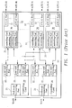
- FIG. 1 shows the structure of the conventional DSLAM equipment.
- a conventional DSLAM equipment 10 includes at least two sets of control cards 20 and plurality line cards 30.
- Each control card 20 includes at least one set of WAN connecting port 21 and plurality sets of line card connecting ports 22.
- the WAN connecting port 21 is connected to the Internet.
- the line card connecting port 22 is correspondingly connected to a control card connecting port 31 of each card 30.
- Each line card 30 has two sets of control card connecting ports 31 for connecting with the control cards 20.
- the line card 30 further has plurality sets of ATU-C ports 32 for correspondingly connecting with the ATU-R (ADSL Modem/Router) at the subscriber end.
- each line card 30 has two sets of control card connecting ports 31 for respectively connecting with the two control cards 20. This is referred to "dual line-connect”.
- Each card 30 has two sets of control card connecting ports 31 so that the volume of circuit of the line card is excessive. In addition, the cost for the parts and connecting lines is increased. Therefore, there can be only one set of redundancy control card 20. In the case that both sets of control cards 20 are in fault state, the DSLAM will fail.
- the present invention is intended to provide a Y-connection scheme for solving above problem.
- Each line card 30 has only one control card connecting port 31 which is connected to at least two sets of control cards via the same connecting line. This can minimize the occupied space of the line card 30 and reduce the cost for the parts. Therefore, more line cards 30 can be arranged in the DSLAM equipment with the same size. Moreover, more then half of the interconnection lines of the conventional DSLAM can be saved.
- the redundancy system employs Y-connection scheme instead of the dual-line connection scheme of conventional DSLAM.
- the redundancy system is designed with a detection means which can automatically switch the control card in removal or fault state. Therefore, the occupied space of the line card of the DSLAM can be minimized and the cost for the parts can be reduced. Also, a large numbers of interconnection lines of the DSLAM can be saved.
- the redundancy system for DSLAM of the present invention includes plurality control cards each having plurality line card connecting ports and more then one network connecting port(s), plurality line cards each having plurality line connecting ports and a control card connecting port and plurality Y-connecting lines.
- the same Y-connecting line is used to connect one of the control card connecting ports with two or more line card connecting ports.
- the method for DSLAM of the present invention includes steps of preparing plurality xTU-C (various digital subscriber line transceiver unit at central office end, such as ADSL, SHDSL (symmetric high speed DSL) and VDSL (Very high speed DSL)) and plurality sets of broadband multiplexers which via Y-connecting lines are correspondingly connected with every xTU-C, continuously detecting whether the broadband multiplexers are in removal or fault state and setting only one set of existing and non-faulting broadband multiplexer in active state to take charge of multiplex processing and connecting the xTU-C with the network and setting the remaining broadband multiplexers in standby state.
- xTU-C variable digital subscriber line transceiver unit at central office end, such as ADSL, SHDSL (symmetric high speed DSL) and VDSL (Very high speed DSL)
- the line card mentioned hereinafter can be applied for ADSL or various digital subscriber lines (xDSL) such as SHDSL and VDSL.
- xDSL digital subscriber lines
- Fig. 2 shows the structure of the connecting lines of the redundancy system of the present invention.
- Fig. 3 is a circuit block diagram of the redundancy system of the present invention.
- the present invention is mainly used in a digital subscriber line access multiplexer (DSLAM) 100.
- the DSLAM serves to providing multiplex accessing to a network 300 such as Internet for a plurality of remote xTU-R 200.
- the xTU-R 200 can be an xDSL modem or router.
- a data bus 110 in the DSLAM of the present invention are disposed a data bus 110, plurality sets of control cards 120 and plurality sets of line cards 130.
- the data bus 110 is connected with a plurality of bus sockets adapted for the control cards 120 and the line cards 130.
- the data bus 110 mainly serves to exchange the data signal of the line cards 130 and the control signal of the control cards 120.
- Each control card 120 has a plurality line card connecting ports 121 and at least one network connecting port 122 for connecting with a wide area network 300.
- optical fiber cable can be used to achieve larger bandwidth.
- At least one set of broadband multiplexer is arranged in the control card 120 for providing multiplex accessing to the network 300 for the line cards 130.
- Each line card 130 has a plurality of line connecting ports 131 and a control card connecting port 123.
- the line connecting ports 131 are correspondingly connected with the xTU-R 200.
- the digital subscriber lines mostly use the conventional ATM lines to connect with the user end.
- Plurality xTU-C are arranged in the line card 130 for correspondingly connecting with the xTU-R 200 (referred to as remote modem apparatuses hereinafter) so as to provide connection access between the remote modem apparatuses 200 and the network.
- the line card 130 of the present invention has only one set of control card connecting port 132. This is different from the conventional DSLAM which has two sets of control card connecting ports. Therefore, the present invention employs plurality Y-connecting lines 140, that is, each control card connecting port 132 uses the same connecting line 140 to connect with the line card connecting ports 121 of two or more sets of control cards 120. Accordingly, over one half of the connecting lines of every line card 130 are saved.
- control card 120 is designed with a detection means for detecting whether only one set of control card 120 is set in the active state and the remaining control cards 120 are in the standby state.
- Fig. 4 is an operation flow chart of the redundancy system of the present invention.
- first, plurality xTU-C and at least two sets of broadband multiplexers (control card) are prepared (step 201).
- the xTU-C are arranged in the DSLAM line card 130, while the broadband multiplexers are arranged in the DSLAM control card 120.
- the Y-connecting line 140 is correspondingly connected with an xTU-C and two sets of broadband multiplexers (step 202). That is, the same connecting line is connected with an xTU-C and two sets of broadband multiplexers. More then two sets of broadband multiplexers could be used for increasing system redundancy reliability.
- step 203 it is continuously detected whether the broadband multiplexers on the Y-connecting line 140 are in removal or fault state. In the case it is detected that plurality sets of broadband multiplexers are in existing and non-fault state, only one set of broadband multiplexer is set in active state to take charge of multiplex processing and connecting the xTU-C with the network. The remaining broadband multiplexers are in the standby state (step 204).
- step 203 In case it is detected that there are broadband multiplexers which are in removal or fault state (step 203), it is judged whether the broadband multiplexers are those in the active state (step 205). If false, it can be ignored. If true, another set of broadband multiplexer in existing and non-fault state is immediately switched and set into active state to continuously take charge of multiplex processing and connect the xTU-C with the network (step 206).
- a control unit 123 and a state recorder 124 can be provided in the control card 120.
- the control unit 123 can control the output/input operation of every line card connecting ports 121 of the control card 120.
- the control units 123 of all the control cards 120 are connected with each other to ensure that only one set of control card 120 in active state.
- the state recorders 124 synchronously record the operation states of the control cards 120 on the Y-connecting lines 140. Accordingly, the control cards on the Y-connecting lines 140 can synchronously control the output/input states of the line card connecting ports 121, that is, control the operation states of the control cards 120. Therefore, the object of automatic switch between the faulting and redundancy broadband multiplexers can be achieved.
- control unit 123 when a new set of control card 120 is inserted into the bus socket on the Y-connecting line 140, the control unit 123 there above immediately reads and duplicates the recorded values in the state recorders 124 on other control cards 120 as well as synchronously changes the recorded values in all the state recorders 124 so as to renew the operation states of the control cards 120.
- the state recorder 123 In the case that there are control cards 120 in removal or fault state, the state recorder 123 will synchronously change the recorded value thereof so as to judge whether the control card 120 is in active state. If true, one redundancy control card is immediately switched and set into active state.
Landscapes
- Engineering & Computer Science (AREA)
- Computer Networks & Wireless Communication (AREA)
- Data Exchanges In Wide-Area Networks (AREA)
- Telephonic Communication Services (AREA)
- Maintenance And Management Of Digital Transmission (AREA)
- Hardware Redundancy (AREA)
- Detection And Prevention Of Errors In Transmission (AREA)
- Time-Division Multiplex Systems (AREA)
Abstract
Description
- The present invention is related to a redundancy system for digital subscriber line access multiplexer (DSLAM), and more particularly to a redundancy system for DSLAM, which is built in a central office end.
- Asymmetric digital subscriber line (ADSL) is a technique utilizing existing twisted-pair telephone line to provide broadband connection with Internet. Recently, the price becomes reasonable so that ADSL has been gradually used instead of conventional dialing connection and Internet private line. More and more business and residential customers have applied ADSL.
- In general, the basic configuration of ADSL includes an ATU-R (ADSL transceiver unit at remote terminal end, i.e, ADSL Modem/Router) at client end connected with an ATU-C (ADSL transceiver unit at central office end) at central office end. This will lead to serious insufficiency of space of the central office. In conventional DSLAM architecture, many ATU-C are designed into card-like modules combined with a DSLAM.
- The requirement for ADSL is gradually increased so that it is necessary for the ADSL service to build a great deal of DSLAM at central office end to satisfy the requirement of a great amount of ADSL clients for connection with Internet.
- For example, every ATU-C port of the DSLAM at the central office end can provide maximum downstream speed of 8Mbps and maximum upstream speed of 1Mbps. The service speed of ADSL is often classified into five grades, that is, downstream/upstream 512K/64K, 768K/128K, 1.5M/384K, 3M/512K and 6M/640K. Therefore, the DSLAM can firstly perform first stage multiplex process in view of the speed grade of the subscriber before substantial processing in the ATU-C port. This can increase the number of the subscribers.
- Fig. 1 shows the structure of the conventional DSLAM equipment. A
conventional DSLAM equipment 10 includes at least two sets ofcontrol cards 20 andplurality line cards 30. Eachcontrol card 20 includes at least one set ofWAN connecting port 21 and plurality sets of linecard connecting ports 22. The WAN connectingport 21 is connected to the Internet. - The line
card connecting port 22 is correspondingly connected to a controlcard connecting port 31 of eachcard 30. Eachline card 30 has two sets of controlcard connecting ports 31 for connecting with thecontrol cards 20. Theline card 30 further has plurality sets of ATU-C ports 32 for correspondingly connecting with the ATU-R (ADSL Modem/Router) at the subscriber end. - One of the two
control cards 20 is in active state, while the other one is in standby state. In the case that theactive control card 20 is in fault or removal state, thestandby control card 20 is immediately set into active state. Therefore, eachline card 30 has two sets of controlcard connecting ports 31 for respectively connecting with the twocontrol cards 20. This is referred to "dual line-connect". - Each
card 30 has two sets of controlcard connecting ports 31 so that the volume of circuit of the line card is excessive. In addition, the cost for the parts and connecting lines is increased. Therefore, there can be only one set ofredundancy control card 20. In the case that both sets ofcontrol cards 20 are in fault state, the DSLAM will fail. - The present invention is intended to provide a Y-connection scheme for solving above problem. Each
line card 30 has only one controlcard connecting port 31 which is connected to at least two sets of control cards via the same connecting line. This can minimize the occupied space of theline card 30 and reduce the cost for the parts. Therefore,more line cards 30 can be arranged in the DSLAM equipment with the same size. Moreover, more then half of the interconnection lines of the conventional DSLAM can be saved. - It is therefore a primary object of the present invention to provide a redundancy system and method for DSLAM. The redundancy system employs Y-connection scheme instead of the dual-line connection scheme of conventional DSLAM. In addition, the redundancy system is designed with a detection means which can automatically switch the control card in removal or fault state. Therefore, the occupied space of the line card of the DSLAM can be minimized and the cost for the parts can be reduced. Also, a large numbers of interconnection lines of the DSLAM can be saved.
- According to the above object, the redundancy system for DSLAM of the present invention includes plurality control cards each having plurality line card connecting ports and more then one network connecting port(s), plurality line cards each having plurality line connecting ports and a control card connecting port and plurality Y-connecting lines. The same Y-connecting line is used to connect one of the control card connecting ports with two or more line card connecting ports. By means of detecting the control cards, the operation state on the Y-connecting lines can be detected switched. One of the control cards is set into active state and the remaining control cards are set into standby state.
- The method for DSLAM of the present invention includes steps of preparing plurality xTU-C (various digital subscriber line transceiver unit at central office end, such as ADSL, SHDSL (symmetric high speed DSL) and VDSL (Very high speed DSL)) and plurality sets of broadband multiplexers which via Y-connecting lines are correspondingly connected with every xTU-C, continuously detecting whether the broadband multiplexers are in removal or fault state and setting only one set of existing and non-faulting broadband multiplexer in active state to take charge of multiplex processing and connecting the xTU-C with the network and setting the remaining broadband multiplexers in standby state.
- The present invention can be best understood through the following description and accompanying drawings wherein:
-
- Fig. 1 shows the structure of a conventional DSLAM equipment;
- Fig. 2 shows the structure of the connecting lines of the redundancy system of the present invention;
- Fig. 3 is a circuit block diagram of the redundancy system of the present invention; and
- Fig. 4 is an operation flow chart of the redundancy system of the present invention.
-
- The line card mentioned hereinafter can be applied for ADSL or various digital subscriber lines (xDSL) such as SHDSL and VDSL.
- Fig. 2 shows the structure of the connecting lines of the redundancy system of the present invention. Fig. 3 is a circuit block diagram of the redundancy system of the present invention. The present invention is mainly used in a digital subscriber line access multiplexer (DSLAM) 100. The DSLAM serves to providing multiplex accessing to a
network 300 such as Internet for a plurality of remote xTU-R 200. The xTU-R 200 can be an xDSL modem or router. - Referring to Fig. 3, in the DSLAM of the present invention are disposed a
data bus 110, plurality sets ofcontrol cards 120 and plurality sets ofline cards 130. Thedata bus 110 is connected with a plurality of bus sockets adapted for thecontrol cards 120 and theline cards 130. Thedata bus 110 mainly serves to exchange the data signal of theline cards 130 and the control signal of thecontrol cards 120. - Each
control card 120 has a plurality linecard connecting ports 121 and at least onenetwork connecting port 122 for connecting with awide area network 300. Preferably, optical fiber cable can be used to achieve larger bandwidth. At least one set of broadband multiplexer is arranged in thecontrol card 120 for providing multiplex accessing to thenetwork 300 for theline cards 130. - Each
line card 130 has a plurality ofline connecting ports 131 and a controlcard connecting port 123. Theline connecting ports 131 are correspondingly connected with the xTU-R 200. Preferably, the digital subscriber lines mostly use the conventional ATM lines to connect with the user end. Plurality xTU-C are arranged in theline card 130 for correspondingly connecting with the xTU-R 200 (referred to as remote modem apparatuses hereinafter) so as to provide connection access between theremote modem apparatuses 200 and the network. - The
line card 130 of the present invention has only one set of controlcard connecting port 132. This is different from the conventional DSLAM which has two sets of control card connecting ports. Therefore, the present invention employs plurality Y-connectinglines 140, that is, each controlcard connecting port 132 uses the same connectingline 140 to connect with the linecard connecting ports 121 of two or more sets ofcontrol cards 120. Accordingly, over one half of the connecting lines of everyline card 130 are saved. - However, on the Y-connecting
line 140 of the present invention, the case of more than one set ofcontrol card 120 present in the active state at the same time should be avoided. Therefore, thecontrol card 120 is designed with a detection means for detecting whether only one set ofcontrol card 120 is set in the active state and the remainingcontrol cards 120 are in the standby state. - Fig. 4 is an operation flow chart of the redundancy system of the present invention. In operation, first, plurality xTU-C and at least two sets of broadband multiplexers (control card) are prepared (step 201). The xTU-C are arranged in the
DSLAM line card 130, while the broadband multiplexers are arranged in theDSLAM control card 120. - Then, the Y-connecting
line 140 is correspondingly connected with an xTU-C and two sets of broadband multiplexers (step 202). That is, the same connecting line is connected with an xTU-C and two sets of broadband multiplexers. More then two sets of broadband multiplexers could be used for increasing system redundancy reliability. - Then, it is continuously detected whether the broadband multiplexers on the Y-connecting
line 140 are in removal or fault state (step 203). In the case it is detected that plurality sets of broadband multiplexers are in existing and non-fault state, only one set of broadband multiplexer is set in active state to take charge of multiplex processing and connecting the xTU-C with the network. The remaining broadband multiplexers are in the standby state (step 204). - In case it is detected that there are broadband multiplexers which are in removal or fault state (step 203), it is judged whether the broadband multiplexers are those in the active state (step 205). If false, it can be ignored. If true, another set of broadband multiplexer in existing and non-fault state is immediately switched and set into active state to continuously take charge of multiplex processing and connect the xTU-C with the network (step 206).
- In order to achieve the objects of detection and automatic switch, in the preferred embodiment of the present invention (further with reference to Fig. 3), a
control unit 123 and astate recorder 124 can be provided in thecontrol card 120. Thecontrol unit 123 can control the output/input operation of every linecard connecting ports 121 of thecontrol card 120. Thecontrol units 123 of all thecontrol cards 120 are connected with each other to ensure that only one set ofcontrol card 120 in active state. - By means of the interconnection between the control units 13, the
state recorders 124 synchronously record the operation states of thecontrol cards 120 on the Y-connectinglines 140. Accordingly, the control cards on the Y-connectinglines 140 can synchronously control the output/input states of the linecard connecting ports 121, that is, control the operation states of thecontrol cards 120. Therefore, the object of automatic switch between the faulting and redundancy broadband multiplexers can be achieved. - For example, when a new set of
control card 120 is inserted into the bus socket on the Y-connectingline 140, thecontrol unit 123 there above immediately reads and duplicates the recorded values in thestate recorders 124 onother control cards 120 as well as synchronously changes the recorded values in all thestate recorders 124 so as to renew the operation states of thecontrol cards 120. In the case that there arecontrol cards 120 in removal or fault state, thestate recorder 123 will synchronously change the recorded value thereof so as to judge whether thecontrol card 120 is in active state. If true, one redundancy control card is immediately switched and set into active state. - The above embodiments are only used to illustrate the present invention, not intended to limit the scope thereof. Many modifications of the above embodiments can be made without departing from the spirit of the present invention.
Claims (13)
- A redundancy system for digital subscriber line access multiplexer (DSLAM), the DSLAM (100) serving to provide multiplex accessing to a network (300) for a plurality of remote xTU-R (200), said redundancy system comprising:a plurality of control cards (120) each having plurality line card connecting ports (121) and a network connecting port (122) for connecting with the network (300);a plurality of line cards (130) each having plurality line connecting ports (131) and a control card connecting port (132), the line connecting ports (131) being correspondingly connected with the xTU-R (200); anda plurality of Y-connecting lines (140), the same Y-connecting line (140) being connected with one of the control card connecting ports (132) and every line card connecting ports (131), whereby, by means of the control cards (120), operation states on the Y-connecting lines (140) can be detected to switch and set one of the control cards (120) into active state and set the remaining control cards (120) into standby state.
- The redundancy system as claimed in claim 1, wherein the xTU-R (200) are ADSL or modem or router of various digital subscriber lines (xDSL) such as ADSL, SHDSL and VDSL.
- The redundancy system as claimed in claim 1, wherein the network is an Internet.
- The redundancy system as claimed in claim 1, wherein the line card (130) includes plurality sets of xDSL xTU-C for correspondingly connecting with the remote xTU-R (200).
- The redundancy system as claimed in claim 1, wherein each control card (120) includes a plurality of broadband multiplexer for providing multiplex accessing to the network (300) for the line cards (130).
- The redundancy system as claimed in claim 1, further comprising:a data bus (110) having a plurality of bus sockets for inserting the control cards (120) and line cards (130) therein, the data bus (110) serving to exchange the data signal of the line cards (130) and the control signal of the control cards (120).
- A redundancy method for DSLAM, the DSLAM (100) serving to provide multiplex accessing to a network (300) for a plurality of remote xTU-R (200), said redundancy method comprising steps of:preparing a plurality of xTU-C for correspondingly connecting with the remote xTU-R (200);preparing plurality sets of broad band multiplexers which via Y-connecting lines (140) are correspondingly connected with every xTU-C;continuously detecting whether the broadband multiplexers are in removal or fault state; andsetting only one set of existing and non-faulting broadband multiplexer in active state to take charge of multiplex processing and connecting the xTU-C with the network (300) and setting the remaining broadband multiplexers in standby state.
- The redundancy method as claimed in claim 7, wherein the xTU-R (200) is xDSL modem or router.
- The redundancy method as claimed in claim 7, wherein the network is an Internet.
- The redundancy method as claimed in claim 7, wherein the xTU-C are arranged on the DSLAM line card (130) for correspondingly connecting with the remote xTU-R (200).
- The redundancy method as claimed in claim 7, wherein the broadband multiplexers are arranged on the DSLAM control card (120).
- The redundancy method as claimed in claim 7, wherein the Y-connecting line (140) is connected between two or more broad band multiplexers and the same network interface card, whereby the same connecting line is connected with one of the line card connecting port (121) and every broadband multiplexers.
- The redundancy method as claimed in claim 7, further comprising a step after preparing plurality sets of broadband multiplexers in case that the broadband multiplexers in operation are removed or in fault state, switching and setting another set of broadband multiplexer which is in existing and non-fault state into active state to continuously take charge of multiplex processing and connecting the xTU-C with the network.
Priority Applications (3)
| Application Number | Priority Date | Filing Date | Title |
|---|---|---|---|
| DE602004011654T DE602004011654T2 (en) | 2004-02-16 | 2004-02-16 | Redundancy system and method for a DSLAM |
| AT04250806T ATE385662T1 (en) | 2004-02-16 | 2004-02-16 | REDUNDANCY SYSTEM AND METHOD FOR A DSLAM |
| EP04250806A EP1565031B1 (en) | 2004-02-16 | 2004-02-16 | Redundancy system and method for a digital subscriber line access multiplexer |
Applications Claiming Priority (1)
| Application Number | Priority Date | Filing Date | Title |
|---|---|---|---|
| EP04250806A EP1565031B1 (en) | 2004-02-16 | 2004-02-16 | Redundancy system and method for a digital subscriber line access multiplexer |
Publications (2)
| Publication Number | Publication Date |
|---|---|
| EP1565031A1 true EP1565031A1 (en) | 2005-08-17 |
| EP1565031B1 EP1565031B1 (en) | 2008-02-06 |
Family
ID=34684771
Family Applications (1)
| Application Number | Title | Priority Date | Filing Date |
|---|---|---|---|
| EP04250806A Expired - Lifetime EP1565031B1 (en) | 2004-02-16 | 2004-02-16 | Redundancy system and method for a digital subscriber line access multiplexer |
Country Status (3)
| Country | Link |
|---|---|
| EP (1) | EP1565031B1 (en) |
| AT (1) | ATE385662T1 (en) |
| DE (1) | DE602004011654T2 (en) |
Cited By (3)
| Publication number | Priority date | Publication date | Assignee | Title |
|---|---|---|---|---|
| CN1929433B (en) * | 2005-09-09 | 2011-04-13 | 华为技术有限公司 | Method and system for interconnection of broad band stationary wireless access-in network and digital user wire network |
| CN1929430B (en) * | 2005-09-09 | 2011-07-20 | 华为技术有限公司 | Method, device and system for interconnection of broad band stationary wireless switch-in network and digital user wire network |
| US9247328B2 (en) | 2011-03-29 | 2016-01-26 | Adtran, Inc. | Systems and methods for moving DSL launch points |
Families Citing this family (1)
| Publication number | Priority date | Publication date | Assignee | Title |
|---|---|---|---|---|
| WO2012135548A1 (en) * | 2011-03-29 | 2012-10-04 | Adtran, Inc. | Systems and methods for connecting dslams to network connections |
-
2004
- 2004-02-16 EP EP04250806A patent/EP1565031B1/en not_active Expired - Lifetime
- 2004-02-16 AT AT04250806T patent/ATE385662T1/en not_active IP Right Cessation
- 2004-02-16 DE DE602004011654T patent/DE602004011654T2/en not_active Expired - Lifetime
Non-Patent Citations (1)
| Title |
|---|
| PAPA DEL J ET AL: "DSLAM - A BROADBAND DIGITAL SUBSCRIBER LINE ACCESS MULTIPLEXER SYSTEM", NEC RESEARCH AND DEVELOPMENT, vol. 40, no. 1, January 1999 (1999-01-01), pages 103 - 107, XP000883831, ISSN: 0547-051X * |
Cited By (4)
| Publication number | Priority date | Publication date | Assignee | Title |
|---|---|---|---|---|
| CN1929433B (en) * | 2005-09-09 | 2011-04-13 | 华为技术有限公司 | Method and system for interconnection of broad band stationary wireless access-in network and digital user wire network |
| CN1929430B (en) * | 2005-09-09 | 2011-07-20 | 华为技术有限公司 | Method, device and system for interconnection of broad band stationary wireless switch-in network and digital user wire network |
| US9247328B2 (en) | 2011-03-29 | 2016-01-26 | Adtran, Inc. | Systems and methods for moving DSL launch points |
| US9332327B2 (en) | 2011-03-29 | 2016-05-03 | Adtran, Inc. | Systems and methods for scaling DSLAM deployments |
Also Published As
| Publication number | Publication date |
|---|---|
| EP1565031B1 (en) | 2008-02-06 |
| DE602004011654D1 (en) | 2008-03-20 |
| DE602004011654T2 (en) | 2009-02-05 |
| ATE385662T1 (en) | 2008-02-15 |
Similar Documents
| Publication | Publication Date | Title |
|---|---|---|
| US6873685B2 (en) | Digital subscriber line access and network testing multiplexer | |
| US6574313B1 (en) | Voice over DSL method and system for supporting a lifeline | |
| US6594343B1 (en) | Splitter bypass architecture for testing multiple ports | |
| US7688744B2 (en) | Broadband test line access circuit, broadband test-line access board and broadband test device | |
| US6754204B1 (en) | Systems and methods for enhanced reliability in a communication system | |
| US20030035377A1 (en) | Method and apparatus for performing dying gasp process for an external digital subscriber line communication terminal | |
| US20060176825A1 (en) | Subscriber line testing system, broadband line card and broadband/narrowband telecommunication system | |
| EP1565031B1 (en) | Redundancy system and method for a digital subscriber line access multiplexer | |
| US6839343B2 (en) | Physical layer router system and method | |
| US6532216B1 (en) | Central office based ADSL test platform | |
| US6775726B2 (en) | Serial unit identification | |
| CN100484022C (en) | System and method for improving communication reliability | |
| CN100466663C (en) | X DSL test method | |
| EP1906635B1 (en) | Access apparatus and method for digital subscriber line test | |
| WO2008025296A1 (en) | Integrated access single board for accessing multiple businesses | |
| US20030035365A1 (en) | Reducing noise communications lines | |
| CN101137073A (en) | Communication network, distribution frame, communication method and distribution frame installation method | |
| EP1906546A1 (en) | A broad-narrow band integrated board and method for testing said board | |
| TWI228359B (en) | Standby system of digital subscriber line access multiplexer | |
| KR100418476B1 (en) | Apparatus And Method For Control And Management Of ATU-C Board In DSLAM System | |
| CN1330165C (en) | Numerical user loop grab wire testing device and method | |
| CN101317429A (en) | Device, system and method for diagnosing intercommunication problem of digital subscriber line transceiver | |
| CN100495997C (en) | Standby system for digital user line multi-task accepting device | |
| CN101252373B (en) | Local terminal equipment, signal separator and communicating system | |
| CN100505799C (en) | 4 line N+1 backup and its detecting circuit |
Legal Events
| Date | Code | Title | Description |
|---|---|---|---|
| PUAI | Public reference made under article 153(3) epc to a published international application that has entered the european phase |
Free format text: ORIGINAL CODE: 0009012 |
|
| AK | Designated contracting states |
Kind code of ref document: A1 Designated state(s): AT BE BG CH CY CZ DE DK EE ES FI FR GB GR HU IE IT LI LU MC NL PT RO SE SI SK TR |
|
| AX | Request for extension of the european patent |
Extension state: AL LT LV MK |
|
| 17P | Request for examination filed |
Effective date: 20060209 |
|
| AKX | Designation fees paid |
Designated state(s): AT BE BG CH CY CZ DE DK EE ES FI FR GB GR HU IE IT LI LU MC NL PT RO SE SI SK TR |
|
| 17Q | First examination report despatched |
Effective date: 20060424 |
|
| RTI1 | Title (correction) |
Free format text: REDUNDANCY SYSTEM AND METHOD FOR A DIGITAL SUBSCRIBER LINE ACCESS MULTIPLEXER |
|
| GRAP | Despatch of communication of intention to grant a patent |
Free format text: ORIGINAL CODE: EPIDOSNIGR1 |
|
| GRAS | Grant fee paid |
Free format text: ORIGINAL CODE: EPIDOSNIGR3 |
|
| GRAA | (expected) grant |
Free format text: ORIGINAL CODE: 0009210 |
|
| AK | Designated contracting states |
Kind code of ref document: B1 Designated state(s): AT BE BG CH CY CZ DE DK EE ES FI FR GB GR HU IE IT LI LU MC NL PT RO SE SI SK TR |
|
| REG | Reference to a national code |
Ref country code: GB Ref legal event code: FG4D |
|
| REG | Reference to a national code |
Ref country code: CH Ref legal event code: EP |
|
| REG | Reference to a national code |
Ref country code: IE Ref legal event code: FG4D |
|
| REF | Corresponds to: |
Ref document number: 602004011654 Country of ref document: DE Date of ref document: 20080320 Kind code of ref document: P |
|
| PG25 | Lapsed in a contracting state [announced via postgrant information from national office to epo] |
Ref country code: FI Free format text: LAPSE BECAUSE OF FAILURE TO SUBMIT A TRANSLATION OF THE DESCRIPTION OR TO PAY THE FEE WITHIN THE PRESCRIBED TIME-LIMIT Effective date: 20080206 Ref country code: ES Free format text: LAPSE BECAUSE OF FAILURE TO SUBMIT A TRANSLATION OF THE DESCRIPTION OR TO PAY THE FEE WITHIN THE PRESCRIBED TIME-LIMIT Effective date: 20080517 |
|
| NLV1 | Nl: lapsed or annulled due to failure to fulfill the requirements of art. 29p and 29m of the patents act | ||
| PG25 | Lapsed in a contracting state [announced via postgrant information from national office to epo] |
Ref country code: AT Free format text: LAPSE BECAUSE OF FAILURE TO SUBMIT A TRANSLATION OF THE DESCRIPTION OR TO PAY THE FEE WITHIN THE PRESCRIBED TIME-LIMIT Effective date: 20080206 |
|
| PG25 | Lapsed in a contracting state [announced via postgrant information from national office to epo] |
Ref country code: SI Free format text: LAPSE BECAUSE OF FAILURE TO SUBMIT A TRANSLATION OF THE DESCRIPTION OR TO PAY THE FEE WITHIN THE PRESCRIBED TIME-LIMIT Effective date: 20080206 Ref country code: BE Free format text: LAPSE BECAUSE OF FAILURE TO SUBMIT A TRANSLATION OF THE DESCRIPTION OR TO PAY THE FEE WITHIN THE PRESCRIBED TIME-LIMIT Effective date: 20080206 |
|
| REG | Reference to a national code |
Ref country code: CH Ref legal event code: PL |
|
| PG25 | Lapsed in a contracting state [announced via postgrant information from national office to epo] |
Ref country code: CZ Free format text: LAPSE BECAUSE OF FAILURE TO SUBMIT A TRANSLATION OF THE DESCRIPTION OR TO PAY THE FEE WITHIN THE PRESCRIBED TIME-LIMIT Effective date: 20080206 Ref country code: NL Free format text: LAPSE BECAUSE OF FAILURE TO SUBMIT A TRANSLATION OF THE DESCRIPTION OR TO PAY THE FEE WITHIN THE PRESCRIBED TIME-LIMIT Effective date: 20080206 Ref country code: SK Free format text: LAPSE BECAUSE OF FAILURE TO SUBMIT A TRANSLATION OF THE DESCRIPTION OR TO PAY THE FEE WITHIN THE PRESCRIBED TIME-LIMIT Effective date: 20080206 Ref country code: SE Free format text: LAPSE BECAUSE OF FAILURE TO SUBMIT A TRANSLATION OF THE DESCRIPTION OR TO PAY THE FEE WITHIN THE PRESCRIBED TIME-LIMIT Effective date: 20080506 Ref country code: PT Free format text: LAPSE BECAUSE OF FAILURE TO SUBMIT A TRANSLATION OF THE DESCRIPTION OR TO PAY THE FEE WITHIN THE PRESCRIBED TIME-LIMIT Effective date: 20080707 Ref country code: CH Free format text: LAPSE BECAUSE OF NON-PAYMENT OF DUE FEES Effective date: 20080229 Ref country code: DK Free format text: LAPSE BECAUSE OF FAILURE TO SUBMIT A TRANSLATION OF THE DESCRIPTION OR TO PAY THE FEE WITHIN THE PRESCRIBED TIME-LIMIT Effective date: 20080206 Ref country code: LI Free format text: LAPSE BECAUSE OF NON-PAYMENT OF DUE FEES Effective date: 20080229 Ref country code: MC Free format text: LAPSE BECAUSE OF NON-PAYMENT OF DUE FEES Effective date: 20080228 |
|
| EN | Fr: translation not filed | ||
| PG25 | Lapsed in a contracting state [announced via postgrant information from national office to epo] |
Ref country code: RO Free format text: LAPSE BECAUSE OF FAILURE TO SUBMIT A TRANSLATION OF THE DESCRIPTION OR TO PAY THE FEE WITHIN THE PRESCRIBED TIME-LIMIT Effective date: 20080206 |
|
| PLBE | No opposition filed within time limit |
Free format text: ORIGINAL CODE: 0009261 |
|
| STAA | Information on the status of an ep patent application or granted ep patent |
Free format text: STATUS: NO OPPOSITION FILED WITHIN TIME LIMIT |
|
| 26N | No opposition filed |
Effective date: 20081107 |
|
| PG25 | Lapsed in a contracting state [announced via postgrant information from national office to epo] |
Ref country code: EE Free format text: LAPSE BECAUSE OF FAILURE TO SUBMIT A TRANSLATION OF THE DESCRIPTION OR TO PAY THE FEE WITHIN THE PRESCRIBED TIME-LIMIT Effective date: 20080206 Ref country code: IE Free format text: LAPSE BECAUSE OF NON-PAYMENT OF DUE FEES Effective date: 20080218 |
|
| PG25 | Lapsed in a contracting state [announced via postgrant information from national office to epo] |
Ref country code: FR Free format text: LAPSE BECAUSE OF FAILURE TO SUBMIT A TRANSLATION OF THE DESCRIPTION OR TO PAY THE FEE WITHIN THE PRESCRIBED TIME-LIMIT Effective date: 20081128 Ref country code: BG Free format text: LAPSE BECAUSE OF FAILURE TO SUBMIT A TRANSLATION OF THE DESCRIPTION OR TO PAY THE FEE WITHIN THE PRESCRIBED TIME-LIMIT Effective date: 20080506 |
|
| PG25 | Lapsed in a contracting state [announced via postgrant information from national office to epo] |
Ref country code: CY Free format text: LAPSE BECAUSE OF FAILURE TO SUBMIT A TRANSLATION OF THE DESCRIPTION OR TO PAY THE FEE WITHIN THE PRESCRIBED TIME-LIMIT Effective date: 20080206 |
|
| PG25 | Lapsed in a contracting state [announced via postgrant information from national office to epo] |
Ref country code: IT Free format text: LAPSE BECAUSE OF FAILURE TO SUBMIT A TRANSLATION OF THE DESCRIPTION OR TO PAY THE FEE WITHIN THE PRESCRIBED TIME-LIMIT Effective date: 20080206 |
|
| PG25 | Lapsed in a contracting state [announced via postgrant information from national office to epo] |
Ref country code: LU Free format text: LAPSE BECAUSE OF NON-PAYMENT OF DUE FEES Effective date: 20080216 Ref country code: HU Free format text: LAPSE BECAUSE OF FAILURE TO SUBMIT A TRANSLATION OF THE DESCRIPTION OR TO PAY THE FEE WITHIN THE PRESCRIBED TIME-LIMIT Effective date: 20080807 |
|
| PG25 | Lapsed in a contracting state [announced via postgrant information from national office to epo] |
Ref country code: TR Free format text: LAPSE BECAUSE OF FAILURE TO SUBMIT A TRANSLATION OF THE DESCRIPTION OR TO PAY THE FEE WITHIN THE PRESCRIBED TIME-LIMIT Effective date: 20080206 |
|
| PG25 | Lapsed in a contracting state [announced via postgrant information from national office to epo] |
Ref country code: GR Free format text: LAPSE BECAUSE OF FAILURE TO SUBMIT A TRANSLATION OF THE DESCRIPTION OR TO PAY THE FEE WITHIN THE PRESCRIBED TIME-LIMIT Effective date: 20080507 |
|
| REG | Reference to a national code |
Ref country code: DE Ref legal event code: R082 Ref document number: 602004011654 Country of ref document: DE Representative=s name: ZEITLER VOLPERT KANDLBINDER, DE Ref country code: DE Ref legal event code: R082 Ref document number: 602004011654 Country of ref document: DE Representative=s name: ZEITLER VOLPERT KANDLBINDER PATENTANWAELTE PAR, DE Ref country code: DE Ref legal event code: R082 Ref document number: 602004011654 Country of ref document: DE Representative=s name: ZEITLER VOLPERT KANDLBINDER PATENT- UND RECHTS, DE |
|
| REG | Reference to a national code |
Ref country code: DE Ref legal event code: R082 Ref document number: 602004011654 Country of ref document: DE |
|
| PGFP | Annual fee paid to national office [announced via postgrant information from national office to epo] |
Ref country code: DE Payment date: 20180228 Year of fee payment: 15 Ref country code: GB Payment date: 20180104 Year of fee payment: 15 |
|
| REG | Reference to a national code |
Ref country code: DE Ref legal event code: R119 Ref document number: 602004011654 Country of ref document: DE |
|
| GBPC | Gb: european patent ceased through non-payment of renewal fee |
Effective date: 20190216 |
|
| PG25 | Lapsed in a contracting state [announced via postgrant information from national office to epo] |
Ref country code: GB Free format text: LAPSE BECAUSE OF NON-PAYMENT OF DUE FEES Effective date: 20190216 Ref country code: DE Free format text: LAPSE BECAUSE OF NON-PAYMENT OF DUE FEES Effective date: 20190903 |