EP1564902A1 - Synchronization processing device and synchronization processing method - Google Patents
Synchronization processing device and synchronization processing method Download PDFInfo
- Publication number
- EP1564902A1 EP1564902A1 EP20040728912 EP04728912A EP1564902A1 EP 1564902 A1 EP1564902 A1 EP 1564902A1 EP 20040728912 EP20040728912 EP 20040728912 EP 04728912 A EP04728912 A EP 04728912A EP 1564902 A1 EP1564902 A1 EP 1564902A1
- Authority
- EP
- European Patent Office
- Prior art keywords
- delay profile
- period
- communicating party
- delay
- stop period
- Prior art date
- Legal status (The legal status is an assumption and is not a legal conclusion. Google has not performed a legal analysis and makes no representation as to the accuracy of the status listed.)
- Withdrawn
Links
Images


Classifications
-
- H—ELECTRICITY
- H04—ELECTRIC COMMUNICATION TECHNIQUE
- H04B—TRANSMISSION
- H04B1/00—Details of transmission systems, not covered by a single one of groups H04B3/00 - H04B13/00; Details of transmission systems not characterised by the medium used for transmission
- H04B1/69—Spread spectrum techniques
- H04B1/707—Spread spectrum techniques using direct sequence modulation
- H04B1/7073—Synchronisation aspects
- H04B1/7075—Synchronisation aspects with code phase acquisition
-
- H—ELECTRICITY
- H04—ELECTRIC COMMUNICATION TECHNIQUE
- H04B—TRANSMISSION
- H04B1/00—Details of transmission systems, not covered by a single one of groups H04B3/00 - H04B13/00; Details of transmission systems not characterised by the medium used for transmission
- H04B1/69—Spread spectrum techniques
- H04B1/707—Spread spectrum techniques using direct sequence modulation
- H04B1/7097—Interference-related aspects
- H04B1/711—Interference-related aspects the interference being multi-path interference
- H04B1/7113—Determination of path profile
-
- H—ELECTRICITY
- H04—ELECTRIC COMMUNICATION TECHNIQUE
- H04B—TRANSMISSION
- H04B1/00—Details of transmission systems, not covered by a single one of groups H04B3/00 - H04B13/00; Details of transmission systems not characterised by the medium used for transmission
- H04B1/69—Spread spectrum techniques
- H04B1/707—Spread spectrum techniques using direct sequence modulation
- H04B1/7097—Interference-related aspects
- H04B1/711—Interference-related aspects the interference being multi-path interference
- H04B1/7115—Constructive combining of multi-path signals, i.e. RAKE receivers
- H04B1/7117—Selection, re-selection, allocation or re-allocation of paths to fingers, e.g. timing offset control of allocated fingers
Definitions
- the present invention relates to a synchronization processing apparatus and a synchronization processing method. More particularly, the present invention relates to a synchronization processing apparatus and a synchronization processing method that create delay profiles and detect receiving timings.
- One common method of receiving processing in a CDMA base station apparatus is to create a delay profile from a correlation value between a received baseband signal a spreading code, and detect the timing of the received path by detecting a peak in the delay profile.
- the base station apparatus must receive multiple channels simultaneously.
- a cellular system generally divides the area that one base station apparatus covers into multiple sectors and provides a transmitting/receiving antenna in each sector. Between the neighboring sectors under the same base station apparatus, an inter-sector HO (handover) is performed. Between the neighboring base station apparatuses, an inter-cell HO is performed.
- a mobile apparatus switches between a normal mode and a compressed mode and communicates with the base station apparatus in accordance with instructions from a higher control station.
- the compressed mode the spread rate for information data frames is reduced on a temporary basis, providing in the frame a time for a transmission-off period and transmitting the frame.
- the mobile apparatus uses this blank time and receives signals of different frequencies from the cell it is in or from the base stations of the neighboring cells. Consequently, when a base station apparatus and a mobile apparatus communicating in a normal mode enter a compressed mode, the base station apparatus, having been communicating up till then, will be unable to receive signals from the mobile apparatus that also has entered the compressed mode, during a certain period of the compressed mode (i.e. transmission-off state in the mobile apparatus).
- delay profile generation multiple channels are subjected to time division processing so as to reduce the hardware scale. That is, the delay profile generation timing per channel--in other words, the baseband signal subject to processing per channel--comes at fixed timings in the base station reference frame or the reference slot.
- FIG.1 illustrates conventional delay profile generation timings of individual channels at fixed timings.
- the base station reference frame of FIG.1 represents the reference frame of the base station apparatus, where one frame is 10ms.
- the delay profile generation timings of FIG. 1 show delay profile generation timings.
- the CM pattern of ch #0 in FIG.1 represents the timing where the mobile apparatus communicating by means of channel #0 enters a transmission-off state in the compressed mode, where [1] represents the transmission-off state and [0] represents the transmission-on state. In FIG.1, time advances toward right.
- delay profiles of all channels are created in order from channel #0.
- the transmission-off timing is determined through operation using compressed mode parameter, and occurs in a predetermined cycle.
- the delay profile creation timing in channel #0 overlaps with the transmission-off timing of the mobile apparatus communicating by means of channel #0, and, in this case, the delay profile of this mobile apparatus having an overlapping timing cannot be generated, which leads to the problem that the receiving timing cannot be detected.
- the above object can be achieved by determining the transmission-off period from compressed mode parameter, which is provided to make the mobile apparatus set a transmission-off period in the compressed mode, and by setting the delay profile creation timings of individual mobile apparatuses such that the delay profile creation period and the transmission-off period do not overlap in any mobile apparatus.
- FIG.2 illustrates the configuration of receiving apparatus 100 having synchronization processing apparatus 110 according to Embodiment 1.
- Synchronization processing apparatus 110 is configured with transmission-off period detector 103, delay profile generation controller 104, delay profile generator 105, and path searcher 106.
- Radio section 102 is a receiver and performs processings on a signal received by antenna 101 including down-conversion from radio frequency to baseband frequency, and outputs the result to delay profile generator 105.
- Transmission-off period detector 103 is a communication-off period detector and determines a transmission-off period from compressed mode parameter received as an input from an unillustrated baseband controller and outputs the result to delay profile generation controller 104.
- the mobile apparatus stops communicating at the timing specified by a higher station apparatus by means of compressed mode parameter.
- the compressed mode parameter determines this transmission-off period, which is a communication-off period, and the length and interval of the transmission-off period.
- Delay profile generation controller 104 is a timing controller and determines, on a per channel basis, whether the delay profile creation period and the transmission-off period in the compressed mode overlap, from channel use state information received as an input from the baseband controller and transmission-off period information received as an input from transmission-off period detector 103. If, as a result of determination, the delay profile creation period and the transmission-off period in the compressed mode overlap, delay profile generation controller 104 instructs delay profile generator 105 to change the order of the channels to have delay profiles created such that the delay profile creation period and the transmission-off period in the compressed mode do not overlap one another.
- the channel use state information refers to information regarding whether each channel is currently being used.
- the mobile station apparatus searches for the base station apparatus of the handover destination. Consequently, to communicate with the base station apparatuses of the neighboring cells, the mobile apparatus temporarily stops communicating with the base station apparatus in the current cell, from which the handover starts.
- Delay profile generator 105 creates delay profiles on a per channel basis, in the order of the channels specified by delay profile generation controller 104. Then, delay profile generator 105 outputs the information of the delay profiles created to path searcher 106.
- path searcher 106 From the delay profile information received as an input from delay profile generator 105, path searcher 106 detects times where the power level has a peak as a received path timing, and outputs receiving path timing information corresponding respectively to the individual channels, detected on a per channel basis, to an unillustrated demodulator, and the demodulator decodes the received signal based on the received path timings.
- transmission-off period detector 103 detects the transmission-off period in the compressed mode from the compressed mode parameter (Step (ST) 201).
- delay profile generation controller 104 determines, on a per channel basis, whether or not the channel is being used (ST202).
- delay profile generation controller 104 determines whether or not the transmission-off period and the delay profile creation period overlap (ST203).
- delay profile generator 105 changes the order of the channels to have delay profiles created by channel units, so as not to make the transmission-off period and the delay profile creation period overlap (ST204).
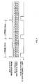
- the base station reference frame in FIG. 4 represents the reference frame of the base station apparatus, and the delay profile creation timings in FIG.4 indicate that delay profiles are created for the individual channels by time division, and the CM pattern of ch #0 in FIG.4 indicates that in ch #0 a transmission-off period occurs at the top of each frame. In FIG.4, time advances toward right.
- the mobile apparatus of a communicating party communicates with the base station apparatus using channel #0.
- Delay profile generation controller 104 controls delay profile generator 105 to create delay profiles in the order of channel #1, channel #2, channel #0, channel #3, channel #4, channel #5, channel #6, and channel #7, so as not to make the delay profile creation period of channel #0 and the transmission off period of channel #0 overlap.
- the delay profile creation period of channel #0 and the transmission-off period of channel #0 do not overlap.
- the transmission-off period of channel #0 recurs at the frequency of once per frame (10 ms) in a regular cycle.
- the mobile apparatus communicating using channel #0 will not have the transmission-off period and the delay profile creation period overlap in any frame.
- the timing of the transmission-off period varies between channels.
- the order of the channels to have delay profiles created is changed such that the transmission-off period and the delay profile creation period do not overlap in any frame. Consequently, each channel has a delay profile created with certainty.
- the transmission-off period and the delay profile creation period do not overlap, and yet there may be other specific channels where there is a likelihood that the transmission-off period and the delay profile creation period overlap in all frames.
- the base station reference frame in FIG.5 represents the reference frame of the base station apparatus, and the delay profile creation timings in FIG.5 indicate that delay profiles are created for the individual channels by time division, and the CM pattern of ch #0 in FIG.5 indicates that in ch #0 a transmission-off period occurs at the top of each frame. In FIG.5, time advances toward right.
- FIG.5 illustrates a case where the order of the channels to have delay profiles created is made to vary on a per frame basis.
- Delayprofile generation controller 104 creates delay profiles in the order of channel #0, channel #1, channel #2, channel #3, channel #4, channel #5, channel #6, and channel #7 in the first frame, creates delay profiles in the order of channel #6, channel #7, channel #0, channel #1, channel #2, channel #3, channel #4, and channel #5 in the next frame, and creates delay profiles in the order of channel #4, channel #5, channel #6, channel #7, channel #0, channel #1, channel #2, and channel #3, in the next frame.
- delay profiles may be created by averaging a plurality of frames, so that each channel has a delay profile created with certainty.
- delay profile generation controller 104 changes the order of the channels to have delay profiles created such that the transmission-off period in the compressed mode and the delay profile creation period do not overlap. Consequently, it is possible to prevent a state where the delay profile of a specific mobile apparatus cannot be created and to detect the receiving timing of each mobile apparatus with certainty.
- FIG.6 illustrates the configuration of receiving apparatus 500 having synchronization processing apparatus 510 according to Embodiment 2.
- Receiving apparatus 500 is another version of receiving apparatus 100 of Embodiment 1 shown in FIG.2, with an addition of received baseband signal switch 504, and with antennas 501-1 -501-n instead of antenna 101 and radio sections 502-1-502-n instead of radio section 102. Parts that are identical to those of FIG.2 will be assigned the same numerals as in FIG.2 without further explanations.
- Synchronization processing apparatus 510 is configured with received baseband signal switch 504, transmission-off period detector 103, delay profile generation controller 104, delay profile generator 105, and path searcher 106.
- Radio sections 502-1 ⁇ 502-n perform processings on signals received by antennas 501-1-501-n including down-conversion from radio frequency to baseband frequency, and outputs the result to received baseband signal switch 504.
- Received baseband signal switch 504 controls, by means of a switch, the received baseband signals of all sectors received as inputs from radio sections 502-1 ⁇ 502-n, as to which sector's received baseband signal is to be output from delay profile generation controller 104 to delay profile generator 105, on a per sector processing basis. The details of received baseband signal switch 504 will be described later.
- delay profile generation controller 104 determines, on a per sector basis, whether or not the delay profile creation period and the transmission-off period in a compressed mode overlap. If, as a result of determination, the delay profile creation period and the transmission-off period in the compressed mode overlap, delay profile generation controller 104 instructs delay profile generator 105 to change the order of the channels to have delay profiles created such that the delay profile creation period and the transmission-off period in the compressed mode do not overlap one another.
- FIG.7 illustrates the configuration of received baseband signal switch 504.
- Received baseband signal switch 504 has the same number of switches 601-1-601-n as radio sections 502-1 ⁇ 502-n, and, in accordance with instructions from delay profile generation controller 104, one of switches 601-1 ⁇ 601-n is selected and turned on, and the rest of switches 601-1 ⁇ 601-n are turned off. Every time one of switches 601-1 ⁇ 601-n is turned on, received baseband signal switch 504 outputs a signal received as an input from radio sections 502-1 ⁇ 502-n, to delay profile generator 105. Received baseband signal switch 504 performs these processings for all of switches 601-1 ⁇ 601-n.
- FIG.8 illustrates a state where cell #702 of base station apparatus 701 is divided into six sectors S1 ⁇ S6.
- mobile apparatus 703 communicates with base station apparatus 701 in the area of sector S1
- base station apparatus 701 creates delay profiles of mobile apparatus 703 in all of sectors S1 ⁇ S6.
- the delay profile of mobile apparatus 703 created at the timing corresponding to sector S1 has the maximum level.
- multiple mobile apparatuses communicate with base station apparatus 701 in sector S1.
- other mobile apparatuses than mobile apparatus 703 will not be described herein.
- the base station reference frame in FIG. 9 represents the reference frame of the base station apparatus, and the delay profile creation timings in FIG. 9 indicate that delay profiles are created for the individual channels by time division, and the CM pattern of ch #0 in FIG.9 indicates that in ch #0, used by mobile apparatus 703, a transmission-off period occurs at the top of each frame. In FIG.9, time advances toward right.
- FIG. 10 shows a single frame in FIG. 9 in detail, where time advances toward right.
- each sector is assigned channels #0 ⁇ #7, and, in the delay profile creation period, the delay profiles of channels #0 ⁇ #7 are created on a per sector basis.
- all sectors are assigned the channels as in sector 1, and so further explanations will be omitted.
- delay profile generation controller 104 controls delay profile generator 105 to create delay profiles in the order of sector S2, sector S3, sector S1, sector S4, sector S5, and sector S6, so as not to make the transmission-off period in channel #0 and the delay profile creation period in channel #0 in sector S1 where mobile apparatus 703 communicates with base station apparatus 701 do not overlap.
- delay profile creation period in channel #0 in sector S1 and the transmission-off period in channel #0 do not overlap.
- the transmission-off period and the delay profile creation period do not overlap, and yet there may be other specific sectors where there is a likelihood that the transmission-off period and the delay profile creation period overlap in all frames.
- the likelihood increases in proportion to the number of channels in use.
- the base station reference frame in FIG.11 represents the reference frame of the base station apparatus, and the delay profile creation timings in FIG.11 indicate that delay profiles are created for the individual channels by time division, and the CM pattern of ch #0 in FIG.11 indicates that in ch #0, a transmission-off period occurs at the top of each frame. In FIG.11, time advances toward right.
- FIG.11 illustrates a case where the order of the sectors to have delay profiles created is made to vary on a per frame basis.
- Delayprofile generation controller 104 creates delay profiles in the order of sector #1, sector #2, sector #3, sector #4, sector #5, and sector #6 in the first frame, creates delay profiles in the order of sector #5, sector #6, sector #1, sector #2, sector #3, and sector #4 in the next frame, and creates delay profiles in the order of sector #3, sector #4, sector #5, sector #6, sector #1, and sector #2 in the next frame.
- delay profiles may be created by averaging a plurality of frames, so that each channel has a delay profile created with certainty.
- delay profile generation controller 104 changes the order of the sectors to have delay profiles created such that the transmission-off period in the compressed mode and the delay profile creation period do not overlap. Consequently, it is possible to prevent a state where the delay profile of a specific mobile apparatus cannot be created and to detect the receiving timing of each mobile apparatus with certainty.
- Embodiment 2 where the number of sectors is 6, the present invention is by no means limited to this and any number will apply.
- the receiving apparatus of Embodiment 2 is applicable to the receiving apparatus of above Embodiment 1.
- the present invention relates to a synchronization processing apparatus and a synchronization processing method.
- the present invention is particularly suitable for use in a synchronization processing apparatus and a synchronization processing method that create delay profiles and detect receiving timings.
Landscapes
- Engineering & Computer Science (AREA)
- Computer Networks & Wireless Communication (AREA)
- Signal Processing (AREA)
- Mobile Radio Communication Systems (AREA)
- Synchronisation In Digital Transmission Systems (AREA)
Abstract
Transmission-off period detector 103 detects the
transmission-off period of the mobile apparatus from
compressed mode parameter. Delay profile generation
controller 104 determines whether or not the
transmission-off period and the delay profile creation
period overlap, and, if the transmission-off period and
the delay profile creation period overlap, instructs
delay profile generator 105 to change the order of the
channels to have delay profiles created. Delay profile
generator 105 creates delay profiles in the order of the
channels indicated by delay profile generation controller
104. Path searcher 105 detects the receiving timing where
a delay profile has a peak. By this means, it is possible
to prevent a state where the delay profile of a specific
communicating party cannot be created, and, consequently,
it is possible to detect each communicating party's
receiving timing with certainty.
Description
- The present invention relates to a synchronization processing apparatus and a synchronization processing method. More particularly, the present invention relates to a synchronization processing apparatus and a synchronization processing method that create delay profiles and detect receiving timings.
- One common method of receiving processing in a CDMA base station apparatus is to create a delay profile from a correlation value between a received baseband signal a spreading code, and detect the timing of the received path by detecting a peak in the delay profile. The base station apparatus must receive multiple channels simultaneously. Also, a cellular system generally divides the area that one base station apparatus covers into multiple sectors and provides a transmitting/receiving antenna in each sector. Between the neighboring sectors under the same base station apparatus, an inter-sector HO (handover) is performed. Between the neighboring base station apparatuses, an inter-cell HO is performed.
- In addition, in accordance with needs, a mobile apparatus switches between a normal mode and a compressed mode and communicates with the base station apparatus in accordance with instructions from a higher control station. In the compressed mode, the spread rate for information data frames is reduced on a temporary basis, providing in the frame a time for a transmission-off period and transmitting the frame. The mobile apparatus uses this blank time and receives signals of different frequencies from the cell it is in or from the base stations of the neighboring cells. Consequently, when a base station apparatus and a mobile apparatus communicating in a normal mode enter a compressed mode, the base station apparatus, having been communicating up till then, will be unable to receive signals from the mobile apparatus that also has entered the compressed mode, during a certain period of the compressed mode (i.e. transmission-off state in the mobile apparatus).
- Conventionally, in delay profile generation, multiple channels are subjected to time division processing so as to reduce the hardware scale. That is, the delay profile generation timing per channel--in other words, the baseband signal subject to processing per channel--comes at fixed timings in the base station reference frame or the reference slot.
- FIG.1 illustrates conventional delay profile generation timings of individual channels at fixed timings. The base station reference frame of FIG.1 represents the reference frame of the base station apparatus, where one frame is 10ms.The delay profile generation timings of FIG. 1 show delay profile generation timings. The CM pattern of
ch # 0 in FIG.1 represents the timing where the mobile apparatus communicating by means ofchannel # 0 enters a transmission-off state in the compressed mode, where [1] represents the transmission-off state and [0] represents the transmission-on state. In FIG.1, time advances toward right. - In every frame, delay profiles of all channels are created in order from
channel # 0. Moreover, the transmission-off timing is determined through operation using compressed mode parameter, and occurs in a predetermined cycle. - However, with the conventional synchronization processing apparatus and the synchronization processing method, for example in the case of FIG.1, the delay profile creation timing in
channel # 0 overlaps with the transmission-off timing of the mobile apparatus communicating by means ofchannel # 0, and, in this case, the delay profile of this mobile apparatus having an overlapping timing cannot be generated, which leads to the problem that the receiving timing cannot be detected. - It is therefore an object of the present invention to provide a synchronization processing apparatus and a synchronization processing method that make it possible to detect each communicating party's receiving timing with certainty by preventing a state where the delay profile of a specific communicating party cannot be created.
- The above object can be achieved by determining the transmission-off period from compressed mode parameter, which is provided to make the mobile apparatus set a transmission-off period in the compressed mode, and by setting the delay profile creation timings of individual mobile apparatuses such that the delay profile creation period and the transmission-off period do not overlap in any mobile apparatus.
-
- FIG.1 illustrates transmission-off period timings and delay profile creation timings;
- FIG.2 is a block diagram showing a configuration
of a receiving apparatus according to
Embodiment 1 of the present invention; - FIG.3 is a flowchart showing operation of the
receiving apparatus according to
Embodiment 1 of the present invention; - FIG.4 illustrates transmission-off period timings and delay profile creation timings;
- FIG.5 illustrates transmission-off period timings and delay profile creation timings;
- FIG.6 is a block diagram showing a configuration
of a receiving apparatus according to
Embodiment 2 of the present invention; - FIG.7 is a block diagram showing a configuration
of a received baseband signal switch according to
Embodiment 2 of the present invention; - FIG.8 is a schematic view representing a mobile apparatus communicating with a base station apparatus in sector S1;
- FIG.9 illustrates transmission-off period timings and delay profile creation timings; FIG.10 illustrates channel assignment in sectors in a frame; and
- FIG.11 illustrates transmission-off period timings and delay profile creation timings.
-
- Now, embodiments of the present invention will be described below in detail with reference to the accompanying drawings.
- FIG.2 illustrates the configuration of receiving
apparatus 100 havingsynchronization processing apparatus 110 according toEmbodiment 1. -
Synchronization processing apparatus 110 is configured with transmission-offperiod detector 103, delayprofile generation controller 104,delay profile generator 105, andpath searcher 106. -
Radio section 102 is a receiver and performs processings on a signal received byantenna 101 including down-conversion from radio frequency to baseband frequency, and outputs the result to delayprofile generator 105. - Transmission-off
period detector 103 is a communication-off period detector and determines a transmission-off period from compressed mode parameter received as an input from an unillustrated baseband controller and outputs the result to delayprofile generation controller 104. In the compressed mode, the mobile apparatus stops communicating at the timing specified by a higher station apparatus by means of compressed mode parameter. The compressed mode parameter determines this transmission-off period, which is a communication-off period, and the length and interval of the transmission-off period. - Delay
profile generation controller 104 is a timing controller and determines, on a per channel basis, whether the delay profile creation period and the transmission-off period in the compressed mode overlap, from channel use state information received as an input from the baseband controller and transmission-off period information received as an input from transmission-offperiod detector 103. If, as a result of determination, the delay profile creation period and the transmission-off period in the compressed mode overlap, delayprofile generation controller 104 instructsdelay profile generator 105 to change the order of the channels to have delay profiles created such that the delay profile creation period and the transmission-off period in the compressed mode do not overlap one another. The channel use state information refers to information regarding whether each channel is currently being used. In the transmission-off period, the mobile station apparatus searches for the base station apparatus of the handover destination. Consequently, to communicate with the base station apparatuses of the neighboring cells, the mobile apparatus temporarily stops communicating with the base station apparatus in the current cell, from which the handover starts. -
Delay profile generator 105 creates delay profiles on a per channel basis, in the order of the channels specified by delayprofile generation controller 104. Then,delay profile generator 105 outputs the information of the delay profiles created to pathsearcher 106. - From the delay profile information received as an input from
delay profile generator 105,path searcher 106 detects times where the power level has a peak as a received path timing, and outputs receiving path timing information corresponding respectively to the individual channels, detected on a per channel basis, to an unillustrated demodulator, and the demodulator decodes the received signal based on the received path timings. - Next, the operation of
synchronization processing apparatus 110 will be described with reference to FIG.3. - First, transmission-off
period detector 103 detects the transmission-off period in the compressed mode from the compressed mode parameter (Step (ST) 201). - Next, from the channel use state information, delay
profile generation controller 104 determines, on a per channel basis, whether or not the channel is being used (ST202). - Next, for those channels that are being used, delay
profile generation controller 104 determines whether or not the transmission-off period and the delay profile creation period overlap (ST203). - If there is a channel in which the transmission-off period and the delay profile creation period overlap,
delay profile generator 105 changes the order of the channels to have delay profiles created by channel units, so as not to make the transmission-off period and the delay profile creation period overlap (ST204). - On the other hand, if in ST203 there are no channels in which the transmission-off period and the delay profile creation period overlap, no rearranging will be applied.
- Next, the method of changing the order of the channels to have delay profiles created in delay
profile generation controller 104 will be described with reference to FIG.4 and FIG.5. A case will be described here with reference to FIG.4 and FIG. 5 where receivingapparatus 100 is applied to a base station apparatus. - The base station reference frame in FIG. 4 represents the reference frame of the base station apparatus, and the delay profile creation timings in FIG.4 indicate that delay profiles are created for the individual channels by time division, and the CM pattern of
ch # 0 in FIG.4 indicates that in ch #0 a transmission-off period occurs at the top of each frame. In FIG.4, time advances toward right. - In FIG.4, the mobile apparatus of a communicating party communicates with the base station apparatus using
channel # 0. Delayprofile generation controller 104 controlsdelay profile generator 105 to create delay profiles in the order ofchannel # 1,channel # 2,channel # 0,channel # 3,channel # 4,channel # 5,channel # 6, andchannel # 7, so as not to make the delay profile creation period ofchannel # 0 and the transmission off period ofchannel # 0 overlap. By this means, as shown in FIG.4, the delay profile creation period ofchannel # 0 and the transmission-off period ofchannel # 0 do not overlap. InEmbodiment 1, the transmission-off period ofchannel # 0 recurs at the frequency of once per frame (10 ms) in a regular cycle. Consequently, by creating delay profiles in the order of the channels shown in FIG.4, the mobile apparatus communicating usingchannel # 0 will not have the transmission-off period and the delay profile creation period overlap in any frame. The timing of the transmission-off period varies between channels. However, the order of the channels to have delay profiles created is changed such that the transmission-off period and the delay profile creation period do not overlap in any frame. Consequently, each channel has a delay profile created with certainty. - Incidentally, if delay profiles are created in the same order of channels in all frames, in some channels the transmission-off period and the delay profile creation period do not overlap, and yet there may be other specific channels where there is a likelihood that the transmission-off period and the delay profile creation period overlap in all frames. The likelihood heightens in proportion to the number of channels in use. As a method for preventing the above-described state, the method of changing the order of the channels to have delay profiles created on a per frame basis is effective, as shown in FIG.5.
- The base station reference frame in FIG.5 represents the reference frame of the base station apparatus, and the delay profile creation timings in FIG.5 indicate that delay profiles are created for the individual channels by time division, and the CM pattern of
ch # 0 in FIG.5 indicates that in ch #0 a transmission-off period occurs at the top of each frame. In FIG.5, time advances toward right. - FIG.5 illustrates a case where the order of the channels to have delay profiles created is made to vary on a per frame basis.
Delayprofile generation controller 104 creates delay profiles in the order ofchannel # 0,channel # 1,channel # 2,channel # 3,channel # 4,channel # 5,channel # 6, andchannel # 7 in the first frame, creates delay profiles in the order ofchannel # 6,channel # 7,channel # 0,channel # 1,channel # 2,channel # 3,channel # 4, andchannel # 5 in the next frame, and creates delay profiles in the order ofchannel # 4,channel # 5,channel # 6,channel # 7,channel # 0,channel # 1,channel # 2, andchannel # 3, in the next frame. - By this means, even when in some specific channels the transmission-off period and the delay profile creation period overlap in some frames, in other frames, the transmission-off period and the delay profile generation period do not overlap. Consequently, with these specific channels, delay profiles may be created by averaging a plurality of frames, so that each channel has a delay profile created with certainty.
- Thus, according to
Embodiment 1, delayprofile generation controller 104 changes the order of the channels to have delay profiles created such that the transmission-off period in the compressed mode and the delay profile creation period do not overlap. Consequently, it is possible to prevent a state where the delay profile of a specific mobile apparatus cannot be created and to detect the receiving timing of each mobile apparatus with certainty. - FIG.6 illustrates the configuration of receiving
apparatus 500 havingsynchronization processing apparatus 510 according toEmbodiment 2. Receivingapparatus 500 is another version of receivingapparatus 100 ofEmbodiment 1 shown in FIG.2, with an addition of receivedbaseband signal switch 504, and with antennas 501-1 -501-n instead ofantenna 101 and radio sections 502-1-502-n instead ofradio section 102. Parts that are identical to those of FIG.2 will be assigned the same numerals as in FIG.2 without further explanations. -
Synchronization processing apparatus 510 is configured with receivedbaseband signal switch 504, transmission-off period detector 103, delayprofile generation controller 104,delay profile generator 105, andpath searcher 106. - Radio sections 502-1~502-n perform processings on signals received by antennas 501-1-501-n including down-conversion from radio frequency to baseband frequency, and outputs the result to received
baseband signal switch 504. - Received
baseband signal switch 504 controls, by means of a switch, the received baseband signals of all sectors received as inputs from radio sections 502-1~502-n, as to which sector's received baseband signal is to be output from delayprofile generation controller 104 to delayprofile generator 105, on a per sector processing basis.
The details of receivedbaseband signal switch 504 will be described later. - From the channel use state information input from a baseband controller and transmission-off period information received as an input from transmission-
off period detector 103, delayprofile generation controller 104 determines, on a per sector basis, whether or not the delay profile creation period and the transmission-off period in a compressed mode overlap. If, as a result of determination, the delay profile creation period and the transmission-off period in the compressed mode overlap, delayprofile generation controller 104 instructsdelay profile generator 105 to change the order of the channels to have delay profiles created such that the delay profile creation period and the transmission-off period in the compressed mode do not overlap one another. - FIG.7 illustrates the configuration of received
baseband signal switch 504. - Received
baseband signal switch 504 has the same number of switches 601-1-601-n as radio sections 502-1~502-n, and, in accordance with instructions from delayprofile generation controller 104, one of switches 601-1~601-n is selected and turned on, and the rest of switches 601-1~601-n are turned off. Every time one of switches 601-1~601-n is turned on, receivedbaseband signal switch 504 outputs a signal received as an input from radio sections 502-1~502-n, to delayprofile generator 105. Receivedbaseband signal switch 504 performs these processings for all of switches 601-1~601-n. - Next, the method of rearranging the timings to create delay profiles in delay
profile generation controller 104 will be described with reference to FIG.8~FIG.11. A case will be described here with reference to FIG.8~FIG.11 where receivingapparatus 500 is applied to a base station apparatus. - FIG.8 illustrates a state where
cell # 702 ofbase station apparatus 701 is divided into six sectors S1~S6. Referring to FIG.8, althoughmobile apparatus 703 communicates withbase station apparatus 701 in the area of sector S1,base station apparatus 701 creates delay profiles ofmobile apparatus 703 in all of sectors S1~S6. In this case, normally, the delay profile ofmobile apparatus 703 created at the timing corresponding to sector S1 has the maximum level. Normally, multiple mobile apparatuses communicate withbase station apparatus 701 in sector S1. However, for ease of explanation, other mobile apparatuses thanmobile apparatus 703 will not be described herein. - The base station reference frame in FIG. 9 represents the reference frame of the base station apparatus, and the delay profile creation timings in FIG. 9 indicate that delay profiles are created for the individual channels by time division, and the CM pattern of
ch # 0 in FIG.9 indicates that inch # 0, used bymobile apparatus 703, a transmission-off period occurs at the top of each frame. In FIG.9, time advances toward right. - FIG. 10 shows a single frame in FIG. 9 in detail, where time advances toward right.
- Referring to FIG.10, each sector is assigned
channels # 0~#7, and, in the delay profile creation period, the delay profiles ofchannels # 0~#7 are created on a per sector basis. In FIG.10, all sectors are assigned the channels as insector 1, and so further explanations will be omitted. - In this case, delay
profile generation controller 104 controls delayprofile generator 105 to create delay profiles in the order of sector S2, sector S3, sector S1, sector S4, sector S5, and sector S6, so as not to make the transmission-off period inchannel # 0 and the delay profile creation period inchannel # 0 in sector S1 wheremobile apparatus 703 communicates withbase station apparatus 701 do not overlap. By this means, as shown in FIG.9, the delay profile creation period inchannel # 0 in sector S1 and the transmission-off period inchannel # 0 do not overlap. - Thus, once the order of the sectors to have delay profiles created is set with respect to one frame, all the other frames need only to adopt the same order. Consequently, simple processing makes it possible to create delay profiles with certainty in which high level peaks can be detected and detect receiving timings with certainty.
- Incidentally, if delay profiles are created in the same order of sectors in all frames, in some sectors the transmission-off period and the delay profile creation period do not overlap, and yet there may be other specific sectors where there is a likelihood that the transmission-off period and the delay profile creation period overlap in all frames. The likelihood increases in proportion to the number of channels in use. As a method for preventing the above-described state, the method of changing the order of the sectors to have delay profiles created on a per frame basis is effective, as shown in FIG.11.
- The base station reference frame in FIG.11 represents the reference frame of the base station apparatus, and the delay profile creation timings in FIG.11 indicate that delay profiles are created for the individual channels by time division, and the CM pattern of
ch # 0 in FIG.11 indicates that inch # 0, a transmission-off period occurs at the top of each frame. In FIG.11, time advances toward right. - FIG.11 illustrates a case where the order of the sectors to have delay profiles created is made to vary on a per frame basis.
Delayprofile generation controller 104 creates delay profiles in the order ofsector # 1,sector # 2,sector # 3,sector # 4,sector # 5, andsector # 6 in the first frame, creates delay profiles in the order ofsector # 5,sector # 6,sector # 1,sector # 2,sector # 3, andsector # 4 in the next frame, and creates delay profiles in the order ofsector # 3,sector # 4,sector # 5,sector # 6,sector # 1, andsector # 2 in the next frame. - By this means, even when in some specific channels the transmission-off period and the delay profile creation period overlap in some frames, in other frames, the transmission-off period and the delay profile generation period do not overlap. Consequently, with these specific channels, delay profiles may be created by averaging a plurality of frames, so that each channel has a delay profile created with certainty.
- Thus, according to
Embodiment 2, delayprofile generation controller 104 changes the order of the sectors to have delay profiles created such that the transmission-off period in the compressed mode and the delay profile creation period do not overlap. Consequently, it is possible to prevent a state where the delay profile of a specific mobile apparatus cannot be created and to detect the receiving timing of each mobile apparatus with certainty. - Although a case has been described with
Embodiment 2 where the number of sectors is 6, the present invention is by no means limited to this and any number will apply. In addition, the receiving apparatus ofEmbodiment 2 is applicable to the receiving apparatus of aboveEmbodiment 1. - Although cases have been described in conjunction with above
Embodiment 1 andEmbodiment 2 where channels #0-#7 are assigned, the present invention is by no means limited to this and any arbitrary number of channels can be provided. Although cases have been described in conjunction with aboveEmbodiment 1 andEmbodiment 2 where a transmission-off period in a compressed mode and a delay profile creation period are controlled not to overlap one another, the present invention is by no means limited to this, and it is equally possible to control a transmission stop period and a delay profile creation period not to overlap one another where a mobile apparatus has to stop transmission on a temporary basis for some reason. - As described above, according to the present invention, it is possible to prevent a state where the delay profile of a specific communicating party cannot be created and detect each communicating party's receiving timing with certainty.
- The present application is based on Japanese Patent Application No.2003-122475, filed April 25, 2003, entire content of which is incorporated herein by reference.
- The present invention relates to a synchronization processing apparatus and a synchronization processing method. The present invention is particularly suitable for use in a synchronization processing apparatus and a synchronization processing method that create delay profiles and detect receiving timings.
Claims (7)
- A synchronization processing apparatus comprising:a delay profile generator that creates a delay profile of a communicating party from a received signal;a communication stop period determiner that determines a temporary communication stop period from a parameter that indicates said communication stop period to the communicating party;a timing controller that sets a delay profile creation timing for the communicating party such that the communication stop period of the communicating party determined by the communication stop period determiner and a delay profile creation period for the communicating party in the delay profile generator do not overlap; anda path searcher that detects a receiving timing where the delay profile has a peak.
- The synchronization processing apparatus of claim 1, wherein:the delay profile generator divides time every plurality of channels and creates delay profiles; andthe timing controller sets delay profile creation timings on a per channel basis.
- The synchronization processing apparatus of claim 1, wherein:the delay profile generator divides time every plurality of sectors and creates delay profiles; andthe timing controller sets delay profile creation timings on a per sector basis.
- The synchronization processing apparatus of claim 1, further comprising receivers provided respectively for the plurality of sectors, wherein the timing controller switches between the receivers by means of a switch and sets delay profile creation timings.
- The synchronization processing apparatus according to claim 1, wherein, when the communicating party searches for a base station apparatus of a handover destination, the communicating party stops transmission and communicates with the base station apparatus in the communication stop period.
- A receiving apparatus having a synchronization processing apparatus, said synchronization processing apparatus comprising:a delay profile generator that creates a delay profile of a communicating party from a received signal;a communication stop period determiner that determines a temporary communication stop period from a parameter that indicates said communication stop period to the communicating party;a timing controller that sets a delay profile creation timing for the communicating party such that the communication stop period of the communicating party determined by the communication stop period determiner and the delay profile creation timing for the communicating party in the delay profile generator do not overlap; anda path searcher that detects a receiving timing where the delay profile has a peak.
- A synchronization processing method comprising the steps of:creating a delay profile of a communicating party from a received signal;determining a temporary communication stop period from a parameter that indicates said communication stop period to the communicating party;setting a delay profile creation timing for the communicating party such that the communication stop period of the communicating party determined by the communication stop period determiner and a delay profile creation period for the communicating party in the delay profile generator do not overlap; anddetecting a receiving timing where the delay profile has a peak.
Applications Claiming Priority (3)
| Application Number | Priority Date | Filing Date | Title |
|---|---|---|---|
| JP2003122475A JP2004328512A (en) | 2003-04-25 | 2003-04-25 | Synchronous processing device and synchronous processing method |
| JP2003122475 | 2003-04-25 | ||
| PCT/JP2004/005792 WO2004098086A1 (en) | 2003-04-25 | 2004-04-22 | Synchronization processing device and synchronization processing method |
Publications (1)
| Publication Number | Publication Date |
|---|---|
| EP1564902A1 true EP1564902A1 (en) | 2005-08-17 |
Family
ID=33410080
Family Applications (1)
| Application Number | Title | Priority Date | Filing Date |
|---|---|---|---|
| EP20040728912 Withdrawn EP1564902A1 (en) | 2003-04-25 | 2004-04-22 | Synchronization processing device and synchronization processing method |
Country Status (4)
| Country | Link |
|---|---|
| EP (1) | EP1564902A1 (en) |
| JP (1) | JP2004328512A (en) |
| CN (1) | CN1723628A (en) |
| WO (1) | WO2004098086A1 (en) |
Families Citing this family (1)
| Publication number | Priority date | Publication date | Assignee | Title |
|---|---|---|---|---|
| US9864399B2 (en) * | 2015-12-10 | 2018-01-09 | Apple Inc. | Timebase synchronization |
Family Cites Families (1)
| Publication number | Priority date | Publication date | Assignee | Title |
|---|---|---|---|---|
| JP3807337B2 (en) * | 2002-04-05 | 2006-08-09 | 日本電気株式会社 | Path search apparatus and method |
-
2003
- 2003-04-25 JP JP2003122475A patent/JP2004328512A/en active Pending
-
2004
- 2004-04-22 EP EP20040728912 patent/EP1564902A1/en not_active Withdrawn
- 2004-04-22 CN CNA2004800016860A patent/CN1723628A/en active Pending
- 2004-04-22 WO PCT/JP2004/005792 patent/WO2004098086A1/en not_active Ceased
Non-Patent Citations (1)
| Title |
|---|
| See references of WO2004098086A1 * |
Also Published As
| Publication number | Publication date |
|---|---|
| WO2004098086A1 (en) | 2004-11-11 |
| JP2004328512A (en) | 2004-11-18 |
| CN1723628A (en) | 2006-01-18 |
Similar Documents
| Publication | Publication Date | Title |
|---|---|---|
| US6400952B2 (en) | Method and apparatus for idle handoff in a cellular system | |
| KR200296459Y1 (en) | A user equipment which determines whether to initiate handover | |
| US7167676B2 (en) | Base station device, mobile station device and transmission power controlling method | |
| US20010006514A1 (en) | Apparatus and method for performing handoff in a mobile communication system | |
| EP0951148A2 (en) | Synchronization apparatus and method for direct sequence spread spectrum communication | |
| MXPA04011049A (en) | Antenna adaptation in a time division duplexing system. | |
| RU2352076C2 (en) | Frame timing and identification of scrambling code in systems of wireless communication and methods for it | |
| EP0872140B1 (en) | A method for selecting the way to perform a handover, and a cellular radio system | |
| EP1096822B1 (en) | Apparatus and method for TDMA-TDD based transmission/reception | |
| EP1396097A1 (en) | Technique for improving open loop power control in spead spectrum telecommunications systems | |
| CN1643964B (en) | Configuration method for compressed mode in mobile wireless communication system | |
| EP1722588B1 (en) | Hard handover method and radio network controller therefor in a mobile telecommunication system | |
| JP4434202B2 (en) | Cell search method for wireless communication system | |
| EP1401225B1 (en) | CDMA type mobile station having a first and a second receiving portion for rounding off a chip offset temporally early and late | |
| KR100380509B1 (en) | Mobile communication terminal and method of detecting received signal strength | |
| CA2240952C (en) | Method and apparatus for base station selection in diversity handover | |
| EP1540868B1 (en) | Method and mobile station for reporting multi-path signals based on a report window | |
| EP1564902A1 (en) | Synchronization processing device and synchronization processing method | |
| CN101461274B (en) | Mobile handoff functionality using asynchronous channel in a communication system | |
| EP1185124A1 (en) | Mobile station apparatus and radio communication method | |
| US20060246928A1 (en) | Synchronization processing apparatus and synchronization processing method | |
| JP2002217819A (en) | Radio communication system and synchronization acquisition control method thereof | |
| JP3781717B2 (en) | Cell search method and mobile station | |
| JP2000354020A (en) | Receiver | |
| EP1340393B1 (en) | Using statistically ascertained position for starting synchronization searcher during diversity handover |
Legal Events
| Date | Code | Title | Description |
|---|---|---|---|
| PUAI | Public reference made under article 153(3) epc to a published international application that has entered the european phase |
Free format text: ORIGINAL CODE: 0009012 |
|
| 17P | Request for examination filed |
Effective date: 20050616 |
|
| AK | Designated contracting states |
Kind code of ref document: A1 Designated state(s): AT BE BG CH CY CZ DE DK EE ES FI FR GB GR HU IE IT LI LU MC NL PL PT RO SE SI SK TR |
|
| AX | Request for extension of the european patent |
Extension state: AL HR LT LV MK |
|
| DAX | Request for extension of the european patent (deleted) | ||
| STAA | Information on the status of an ep patent application or granted ep patent |
Free format text: STATUS: THE APPLICATION HAS BEEN WITHDRAWN |
|
| 18W | Application withdrawn |
Effective date: 20080410 |