EP1564827A1 - Method for the manufacturing of multilayer mesogenic components - Google Patents
Method for the manufacturing of multilayer mesogenic components Download PDFInfo
- Publication number
- EP1564827A1 EP1564827A1 EP04447034A EP04447034A EP1564827A1 EP 1564827 A1 EP1564827 A1 EP 1564827A1 EP 04447034 A EP04447034 A EP 04447034A EP 04447034 A EP04447034 A EP 04447034A EP 1564827 A1 EP1564827 A1 EP 1564827A1
- Authority
- EP
- European Patent Office
- Prior art keywords
- mesogenic
- layer
- materials
- discotic
- group
- Prior art date
- Legal status (The legal status is an assumption and is not a legal conclusion. Google has not performed a legal analysis and makes no representation as to the accuracy of the status listed.)
- Withdrawn
Links
- 238000000034 method Methods 0.000 title claims abstract description 37
- 238000004519 manufacturing process Methods 0.000 title claims abstract description 16
- 239000000463 material Substances 0.000 claims abstract description 106
- 239000002904 solvent Substances 0.000 claims abstract description 44
- 238000000151 deposition Methods 0.000 claims abstract description 17
- 239000000758 substrate Substances 0.000 claims abstract description 16
- 230000008021 deposition Effects 0.000 claims abstract description 5
- 238000005406 washing Methods 0.000 claims abstract description 5
- -1 ethyleneoxy units Chemical group 0.000 claims description 15
- RTZKZFJDLAIYFH-UHFFFAOYSA-N Diethyl ether Chemical compound CCOCC RTZKZFJDLAIYFH-UHFFFAOYSA-N 0.000 claims description 14
- 238000004528 spin coating Methods 0.000 claims description 14
- 125000004429 atom Chemical group 0.000 claims description 13
- 150000002148 esters Chemical class 0.000 claims description 13
- BASFCYQUMIYNBI-UHFFFAOYSA-N platinum Substances [Pt] BASFCYQUMIYNBI-UHFFFAOYSA-N 0.000 claims description 12
- 229910052757 nitrogen Inorganic materials 0.000 claims description 11
- 125000001931 aliphatic group Chemical group 0.000 claims description 10
- 150000001408 amides Chemical class 0.000 claims description 10
- 229910052794 bromium Inorganic materials 0.000 claims description 10
- 229910052801 chlorine Inorganic materials 0.000 claims description 10
- 229910052731 fluorine Inorganic materials 0.000 claims description 10
- 229910052739 hydrogen Inorganic materials 0.000 claims description 10
- 229910052740 iodine Inorganic materials 0.000 claims description 10
- LFQSCWFLJHTTHZ-UHFFFAOYSA-N Ethanol Chemical compound CCO LFQSCWFLJHTTHZ-UHFFFAOYSA-N 0.000 claims description 9
- KDLHZDBZIXYQEI-UHFFFAOYSA-N Palladium Chemical compound [Pd] KDLHZDBZIXYQEI-UHFFFAOYSA-N 0.000 claims description 9
- 239000010949 copper Substances 0.000 claims description 9
- 239000007788 liquid Substances 0.000 claims description 9
- 229910052751 metal Inorganic materials 0.000 claims description 9
- 239000002184 metal Substances 0.000 claims description 9
- 150000003839 salts Chemical class 0.000 claims description 9
- IJGRMHOSHXDMSA-UHFFFAOYSA-N Atomic nitrogen Chemical compound N#N IJGRMHOSHXDMSA-UHFFFAOYSA-N 0.000 claims description 8
- 229910006069 SO3H Inorganic materials 0.000 claims description 7
- YTPLMLYBLZKORZ-UHFFFAOYSA-N Thiophene Chemical compound C=1C=CSC=1 YTPLMLYBLZKORZ-UHFFFAOYSA-N 0.000 claims description 7
- 150000001336 alkenes Chemical class 0.000 claims description 7
- 150000001345 alkine derivatives Chemical class 0.000 claims description 7
- 125000000524 functional group Chemical group 0.000 claims description 7
- 125000005842 heteroatom Chemical group 0.000 claims description 7
- 125000000896 monocarboxylic acid group Chemical group 0.000 claims description 7
- 229910052760 oxygen Inorganic materials 0.000 claims description 7
- 125000001997 phenyl group Chemical group [H]C1=C([H])C([H])=C(*)C([H])=C1[H] 0.000 claims description 7
- 125000000020 sulfo group Chemical group O=S(=O)([*])O[H] 0.000 claims description 7
- 125000000217 alkyl group Chemical group 0.000 claims description 6
- 125000004432 carbon atom Chemical group C* 0.000 claims description 6
- 229910052802 copper Inorganic materials 0.000 claims description 6
- 229910052697 platinum Inorganic materials 0.000 claims description 6
- XLYOFNOQVPJJNP-UHFFFAOYSA-N water Substances O XLYOFNOQVPJJNP-UHFFFAOYSA-N 0.000 claims description 6
- 238000010345 tape casting Methods 0.000 claims description 5
- 238000005266 casting Methods 0.000 claims description 4
- 239000011521 glass Substances 0.000 claims description 4
- 230000003287 optical effect Effects 0.000 claims description 4
- RYGMFSIKBFXOCR-UHFFFAOYSA-N Copper Chemical compound [Cu] RYGMFSIKBFXOCR-UHFFFAOYSA-N 0.000 claims description 3
- YZCKVEUIGOORGS-OUBTZVSYSA-N Deuterium Chemical compound [2H] YZCKVEUIGOORGS-OUBTZVSYSA-N 0.000 claims description 3
- 239000002253 acid Substances 0.000 claims description 3
- 150000001338 aliphatic hydrocarbons Chemical class 0.000 claims description 3
- 150000001412 amines Chemical class 0.000 claims description 3
- 150000004945 aromatic hydrocarbons Chemical class 0.000 claims description 3
- 229910052805 deuterium Inorganic materials 0.000 claims description 3
- 229910052736 halogen Inorganic materials 0.000 claims description 3
- 150000002367 halogens Chemical class 0.000 claims description 3
- 229930195733 hydrocarbon Natural products 0.000 claims description 3
- 150000002430 hydrocarbons Chemical class 0.000 claims description 3
- 239000001257 hydrogen Substances 0.000 claims description 3
- 150000002576 ketones Chemical class 0.000 claims description 3
- 125000000449 nitro group Chemical group [O-][N+](*)=O 0.000 claims description 3
- 125000005245 nitryl group Chemical group [N+](=O)([O-])* 0.000 claims description 3
- 229910052763 palladium Inorganic materials 0.000 claims description 3
- 239000004033 plastic Substances 0.000 claims description 3
- 229920003023 plastic Polymers 0.000 claims description 3
- JBQYATWDVHIOAR-UHFFFAOYSA-N tellanylidenegermanium Chemical compound [Te]=[Ge] JBQYATWDVHIOAR-UHFFFAOYSA-N 0.000 claims description 3
- 229930192474 thiophene Natural products 0.000 claims description 3
- 229910052725 zinc Inorganic materials 0.000 claims description 3
- 239000011701 zinc Substances 0.000 claims description 3
- ORNUPNRNNSVZTC-UHFFFAOYSA-N 2-vinylthiophene Chemical group C=CC1=CC=CS1 ORNUPNRNNSVZTC-UHFFFAOYSA-N 0.000 claims description 2
- 238000001074 Langmuir--Blodgett assembly Methods 0.000 claims description 2
- JCXJVPUVTGWSNB-UHFFFAOYSA-N Nitrogen dioxide Chemical compound O=[N]=O JCXJVPUVTGWSNB-UHFFFAOYSA-N 0.000 claims 2
- 125000001033 ether group Chemical group 0.000 claims 1
- 125000004435 hydrogen atom Chemical group [H]* 0.000 claims 1
- CSCPPACGZOOCGX-UHFFFAOYSA-N Acetone Chemical compound CC(C)=O CSCPPACGZOOCGX-UHFFFAOYSA-N 0.000 description 18
- 239000000243 solution Substances 0.000 description 16
- YXFVVABEGXRONW-UHFFFAOYSA-N Toluene Chemical compound CC1=CC=CC=C1 YXFVVABEGXRONW-UHFFFAOYSA-N 0.000 description 15
- 239000004973 liquid crystal related substance Substances 0.000 description 13
- 238000009987 spinning Methods 0.000 description 11
- 239000010408 film Substances 0.000 description 9
- VLKZOEOYAKHREP-UHFFFAOYSA-N n-Hexane Chemical compound CCCCCC VLKZOEOYAKHREP-UHFFFAOYSA-N 0.000 description 9
- 239000004065 semiconductor Substances 0.000 description 9
- HEDRZPFGACZZDS-UHFFFAOYSA-N Chloroform Chemical compound ClC(Cl)Cl HEDRZPFGACZZDS-UHFFFAOYSA-N 0.000 description 8
- YMWUJEATGCHHMB-UHFFFAOYSA-N Dichloromethane Chemical compound ClCCl YMWUJEATGCHHMB-UHFFFAOYSA-N 0.000 description 6
- OKKJLVBELUTLKV-UHFFFAOYSA-N Methanol Chemical compound OC OKKJLVBELUTLKV-UHFFFAOYSA-N 0.000 description 6
- XJHCXCQVJFPJIK-UHFFFAOYSA-M caesium fluoride Chemical compound [F-].[Cs+] XJHCXCQVJFPJIK-UHFFFAOYSA-M 0.000 description 6
- 239000004985 Discotic Liquid Crystal Substance Substances 0.000 description 5
- 238000000576 coating method Methods 0.000 description 5
- IEQIEDJGQAUEQZ-UHFFFAOYSA-N phthalocyanine Chemical class N1C(N=C2C3=CC=CC=C3C(N=C3C4=CC=CC=C4C(=N4)N3)=N2)=C(C=CC=C2)C2=C1N=C1C2=CC=CC=C2C4=N1 IEQIEDJGQAUEQZ-UHFFFAOYSA-N 0.000 description 5
- 229910052717 sulfur Inorganic materials 0.000 description 5
- MWPLVEDNUUSJAV-UHFFFAOYSA-N anthracene Chemical compound C1=CC=CC2=CC3=CC=CC=C3C=C21 MWPLVEDNUUSJAV-UHFFFAOYSA-N 0.000 description 4
- 239000011248 coating agent Substances 0.000 description 4
- AMGQUBHHOARCQH-UHFFFAOYSA-N indium;oxotin Chemical compound [In].[Sn]=O AMGQUBHHOARCQH-UHFFFAOYSA-N 0.000 description 4
- 239000005020 polyethylene terephthalate Substances 0.000 description 4
- BBEAQIROQSPTKN-UHFFFAOYSA-N pyrene Chemical compound C1=CC=C2C=CC3=CC=CC4=CC=C1C2=C43 BBEAQIROQSPTKN-UHFFFAOYSA-N 0.000 description 4
- VYPSYNLAJGMNEJ-UHFFFAOYSA-N silicon dioxide Inorganic materials O=[Si]=O VYPSYNLAJGMNEJ-UHFFFAOYSA-N 0.000 description 4
- QTBSBXVTEAMEQO-UHFFFAOYSA-N Acetic acid Chemical compound CC(O)=O QTBSBXVTEAMEQO-UHFFFAOYSA-N 0.000 description 3
- 238000000862 absorption spectrum Methods 0.000 description 3
- 230000001133 acceleration Effects 0.000 description 3
- 239000004411 aluminium Substances 0.000 description 3
- 229910052782 aluminium Inorganic materials 0.000 description 3
- XAGFODPZIPBFFR-UHFFFAOYSA-N aluminium Chemical compound [Al] XAGFODPZIPBFFR-UHFFFAOYSA-N 0.000 description 3
- 125000003118 aryl group Chemical group 0.000 description 3
- 230000015572 biosynthetic process Effects 0.000 description 3
- PQXKHYXIUOZZFA-UHFFFAOYSA-M lithium fluoride Chemical compound [Li+].[F-] PQXKHYXIUOZZFA-UHFFFAOYSA-M 0.000 description 3
- 229910044991 metal oxide Inorganic materials 0.000 description 3
- 150000004706 metal oxides Chemical class 0.000 description 3
- 239000011368 organic material Substances 0.000 description 3
- 229920001343 polytetrafluoroethylene Polymers 0.000 description 3
- 239000004810 polytetrafluoroethylene Substances 0.000 description 3
- 229910052709 silver Inorganic materials 0.000 description 3
- 239000004332 silver Substances 0.000 description 3
- MDCIYXHEPARHMN-UHFFFAOYSA-N 3,5,6,7,8,30-hexazaheptacyclo[20.8.0.02,11.04,9.012,21.014,19.024,29]triaconta-1(30),2,4(9),5,7,10,12,14,16,18,20,22,24,26,28-pentadecaene Chemical group N1=NN=C2C=C3C4=CC5=CC=CC=C5C=C4C4=CC5=CC=CC=C5N=C4C3=NC2=N1 MDCIYXHEPARHMN-UHFFFAOYSA-N 0.000 description 2
- XKRFYHLGVUSROY-UHFFFAOYSA-N Argon Chemical compound [Ar] XKRFYHLGVUSROY-UHFFFAOYSA-N 0.000 description 2
- KFZMGEQAYNKOFK-UHFFFAOYSA-N Isopropanol Chemical compound CC(C)O KFZMGEQAYNKOFK-UHFFFAOYSA-N 0.000 description 2
- UFWIBTONFRDIAS-UHFFFAOYSA-N Naphthalene Chemical compound C1=CC=CC2=CC=CC=C21 UFWIBTONFRDIAS-UHFFFAOYSA-N 0.000 description 2
- 239000005062 Polybutadiene Substances 0.000 description 2
- 239000004698 Polyethylene Substances 0.000 description 2
- 239000004743 Polypropylene Substances 0.000 description 2
- BQCADISMDOOEFD-UHFFFAOYSA-N Silver Chemical compound [Ag] BQCADISMDOOEFD-UHFFFAOYSA-N 0.000 description 2
- 229920004933 Terylene® Polymers 0.000 description 2
- XLOMVQKBTHCTTD-UHFFFAOYSA-N Zinc monoxide Chemical compound [Zn]=O XLOMVQKBTHCTTD-UHFFFAOYSA-N 0.000 description 2
- 238000010382 chemical cross-linking Methods 0.000 description 2
- 238000006243 chemical reaction Methods 0.000 description 2
- 238000005229 chemical vapour deposition Methods 0.000 description 2
- 230000000295 complement effect Effects 0.000 description 2
- 238000005137 deposition process Methods 0.000 description 2
- GVEPBJHOBDJJJI-UHFFFAOYSA-N fluoranthrene Natural products C1=CC(C2=CC=CC=C22)=C3C2=CC=CC3=C1 GVEPBJHOBDJJJI-UHFFFAOYSA-N 0.000 description 2
- PCHJSUWPFVWCPO-UHFFFAOYSA-N gold Chemical compound [Au] PCHJSUWPFVWCPO-UHFFFAOYSA-N 0.000 description 2
- 229910052737 gold Inorganic materials 0.000 description 2
- 239000010931 gold Substances 0.000 description 2
- 150000002431 hydrogen Chemical class 0.000 description 2
- 239000000203 mixture Substances 0.000 description 2
- 125000002080 perylenyl group Chemical group C1(=CC=C2C=CC=C3C4=CC=CC5=CC=CC(C1=C23)=C45)* 0.000 description 2
- CSHWQDPOILHKBI-UHFFFAOYSA-N peryrene Natural products C1=CC(C2=CC=CC=3C2=C2C=CC=3)=C3C2=CC=CC3=C1 CSHWQDPOILHKBI-UHFFFAOYSA-N 0.000 description 2
- 229920001467 poly(styrenesulfonates) Polymers 0.000 description 2
- 229920002857 polybutadiene Polymers 0.000 description 2
- 229920000139 polyethylene terephthalate Polymers 0.000 description 2
- 229920001155 polypropylene Polymers 0.000 description 2
- 239000004814 polyurethane Substances 0.000 description 2
- 229920002635 polyurethane Polymers 0.000 description 2
- 239000010453 quartz Substances 0.000 description 2
- 238000010992 reflux Methods 0.000 description 2
- 238000001228 spectrum Methods 0.000 description 2
- 239000010409 thin film Substances 0.000 description 2
- 239000008096 xylene Substances 0.000 description 2
- IJAAWBHHXIWAHM-PHEQNACWSA-N 1,4-bis[(e)-2-phenylethenyl]benzene Chemical compound C=1C=CC=CC=1/C=C/C(C=C1)=CC=C1\C=C\C1=CC=CC=C1 IJAAWBHHXIWAHM-PHEQNACWSA-N 0.000 description 1
- KXSFECAJUBPPFE-UHFFFAOYSA-N 2,2':5',2''-terthiophene Chemical compound C1=CSC(C=2SC(=CC=2)C=2SC=CC=2)=C1 KXSFECAJUBPPFE-UHFFFAOYSA-N 0.000 description 1
- HEYRZXKTUUUXKL-UHFFFAOYSA-N 2,5-diphenylpyrimidine Chemical compound C1=CC=CC=C1C1=CN=C(C=2C=CC=CC=2)N=C1 HEYRZXKTUUUXKL-UHFFFAOYSA-N 0.000 description 1
- MZBIWFMZBZJUHX-UHFFFAOYSA-N 2,6-diphenylanthracene Chemical compound C1=CC=CC=C1C1=CC=C(C=C2C(C=CC(=C2)C=2C=CC=CC=2)=C2)C2=C1 MZBIWFMZBZJUHX-UHFFFAOYSA-N 0.000 description 1
- XBHOUXSGHYZCNH-UHFFFAOYSA-N 2-phenyl-1,3-benzothiazole Chemical compound C1=CC=CC=C1C1=NC2=CC=CC=C2S1 XBHOUXSGHYZCNH-UHFFFAOYSA-N 0.000 description 1
- CPFKXWHSCZUOFQ-UHFFFAOYSA-N 2-phenyl-5-(4-phenylphenyl)-2,5-dihydro-1,3,4-oxadiazole Chemical compound O1C(N=NC1c1ccc(cc1)-c1ccccc1)c1ccccc1 CPFKXWHSCZUOFQ-UHFFFAOYSA-N 0.000 description 1
- DMEVMYSQZPJFOK-UHFFFAOYSA-N 3,4,5,6,9,10-hexazatetracyclo[12.4.0.02,7.08,13]octadeca-1(18),2(7),3,5,8(13),9,11,14,16-nonaene Chemical group N1=NN=C2C3=CC=CC=C3C3=CC=NN=C3C2=N1 DMEVMYSQZPJFOK-UHFFFAOYSA-N 0.000 description 1
- HEQCMHJJSHHJGN-UHFFFAOYSA-N 3,5,8,10,13,15,18,20,23,25,28,30-dodecazaheptacyclo[20.8.0.02,11.04,9.012,21.014,19.024,29]triaconta-1(30),2,4,6,8,10,12,14,16,18,20,22,24,26,28-pentadecaene Chemical group C1=CN=C2N=C3C4=NC5=NC=CN=C5N=C4C4=NC5=NC=CN=C5N=C4C3=NC2=N1 HEQCMHJJSHHJGN-UHFFFAOYSA-N 0.000 description 1
- JWBHNEZMQMERHA-UHFFFAOYSA-N 5,6,11,12,17,18-hexaazatrinaphthylene Chemical group C1=CC=C2N=C3C4=NC5=CC=CC=C5N=C4C4=NC5=CC=CC=C5N=C4C3=NC2=C1 JWBHNEZMQMERHA-UHFFFAOYSA-N 0.000 description 1
- OYPRJOBELJOOCE-UHFFFAOYSA-N Calcium Chemical compound [Ca] OYPRJOBELJOOCE-UHFFFAOYSA-N 0.000 description 1
- FYYHWMGAXLPEAU-UHFFFAOYSA-N Magnesium Chemical compound [Mg] FYYHWMGAXLPEAU-UHFFFAOYSA-N 0.000 description 1
- CTQNGGLPUBDAKN-UHFFFAOYSA-N O-Xylene Chemical compound CC1=CC=CC=C1C CTQNGGLPUBDAKN-UHFFFAOYSA-N 0.000 description 1
- 229920005372 Plexiglas® Polymers 0.000 description 1
- 239000004793 Polystyrene Substances 0.000 description 1
- XBDYBAVJXHJMNQ-UHFFFAOYSA-N Tetrahydroanthracene Natural products C1=CC=C2C=C(CCCC3)C3=CC2=C1 XBDYBAVJXHJMNQ-UHFFFAOYSA-N 0.000 description 1
- GWEVSGVZZGPLCZ-UHFFFAOYSA-N Titan oxide Chemical compound O=[Ti]=O GWEVSGVZZGPLCZ-UHFFFAOYSA-N 0.000 description 1
- SLGBZMMZGDRARJ-UHFFFAOYSA-N Triphenylene Natural products C1=CC=C2C3=CC=CC=C3C3=CC=CC=C3C2=C1 SLGBZMMZGDRARJ-UHFFFAOYSA-N 0.000 description 1
- 239000003570 air Substances 0.000 description 1
- 229910052786 argon Inorganic materials 0.000 description 1
- 229910052791 calcium Inorganic materials 0.000 description 1
- 239000011575 calcium Substances 0.000 description 1
- 230000001143 conditioned effect Effects 0.000 description 1
- 229920000547 conjugated polymer Polymers 0.000 description 1
- 229920001577 copolymer Polymers 0.000 description 1
- 239000002178 crystalline material Substances 0.000 description 1
- 230000006866 deterioration Effects 0.000 description 1
- 229960004132 diethyl ether Drugs 0.000 description 1
- AJNVQOSZGJRYEI-UHFFFAOYSA-N digallium;oxygen(2-) Chemical compound [O-2].[O-2].[O-2].[Ga+3].[Ga+3] AJNVQOSZGJRYEI-UHFFFAOYSA-N 0.000 description 1
- XUCJHNOBJLKZNU-UHFFFAOYSA-M dilithium;hydroxide Chemical compound [Li+].[Li+].[OH-] XUCJHNOBJLKZNU-UHFFFAOYSA-M 0.000 description 1
- 230000005684 electric field Effects 0.000 description 1
- 230000005611 electricity Effects 0.000 description 1
- 230000005669 field effect Effects 0.000 description 1
- 229910001195 gallium oxide Inorganic materials 0.000 description 1
- QRRKXCPLJGPVHN-UHFFFAOYSA-N hexabenzocoronene Chemical compound C12C(C(=C34)C(=C56)C7=C89)=C%10C7=C7C%11=CC=CC7=C8C=CC=C9C5=CC=CC6=C3C=CC=C4C1=CC=CC2=C1C%10=C%11C=CC1 QRRKXCPLJGPVHN-UHFFFAOYSA-N 0.000 description 1
- 238000002347 injection Methods 0.000 description 1
- 239000007924 injection Substances 0.000 description 1
- WBQFFOYISYSHLE-UHFFFAOYSA-N isoindole-1,3-dione Chemical compound C1=CC=C2C(=O)[N]C(=O)C2=C1 WBQFFOYISYSHLE-UHFFFAOYSA-N 0.000 description 1
- 230000031700 light absorption Effects 0.000 description 1
- FUJCRWPEOMXPAD-UHFFFAOYSA-N lithium oxide Chemical compound [Li+].[Li+].[O-2] FUJCRWPEOMXPAD-UHFFFAOYSA-N 0.000 description 1
- 229910001947 lithium oxide Inorganic materials 0.000 description 1
- 239000011777 magnesium Substances 0.000 description 1
- 229910052749 magnesium Inorganic materials 0.000 description 1
- 239000011159 matrix material Substances 0.000 description 1
- 150000002739 metals Chemical class 0.000 description 1
- 239000010445 mica Substances 0.000 description 1
- 229910052618 mica group Inorganic materials 0.000 description 1
- 238000004377 microelectronic Methods 0.000 description 1
- 229920000620 organic polymer Polymers 0.000 description 1
- SIWVEOZUMHYXCS-UHFFFAOYSA-N oxo(oxoyttriooxy)yttrium Chemical compound O=[Y]O[Y]=O SIWVEOZUMHYXCS-UHFFFAOYSA-N 0.000 description 1
- MMKQUGHLEMYQSG-UHFFFAOYSA-N oxygen(2-);praseodymium(3+) Chemical compound [O-2].[O-2].[O-2].[Pr+3].[Pr+3] MMKQUGHLEMYQSG-UHFFFAOYSA-N 0.000 description 1
- SLIUAWYAILUBJU-UHFFFAOYSA-N pentacene Chemical compound C1=CC=CC2=CC3=CC4=CC5=CC=CC=C5C=C4C=C3C=C21 SLIUAWYAILUBJU-UHFFFAOYSA-N 0.000 description 1
- DGBWPZSGHAXYGK-UHFFFAOYSA-N perinone Chemical compound C12=NC3=CC=CC=C3N2C(=O)C2=CC=C3C4=C2C1=CC=C4C(=O)N1C2=CC=CC=C2N=C13 DGBWPZSGHAXYGK-UHFFFAOYSA-N 0.000 description 1
- GDUSKTLXJLABPR-UHFFFAOYSA-N perylene-1,2-dicarboximidamide Chemical compound C1=CC(C2=C(C(C(=N)N)=CC=3C2=C2C=CC=3)C(N)=N)=C3C2=CC=CC3=C1 GDUSKTLXJLABPR-UHFFFAOYSA-N 0.000 description 1
- INAAIJLSXJJHOZ-UHFFFAOYSA-N pibenzimol Chemical compound C1CN(C)CCN1C1=CC=C(N=C(N2)C=3C=C4NC(=NC4=CC=3)C=3C=CC(O)=CC=3)C2=C1 INAAIJLSXJJHOZ-UHFFFAOYSA-N 0.000 description 1
- 229920000767 polyaniline Polymers 0.000 description 1
- 229920000573 polyethylene Polymers 0.000 description 1
- 229920000193 polymethacrylate Polymers 0.000 description 1
- 239000004926 polymethyl methacrylate Substances 0.000 description 1
- 229920000128 polypyrrole Polymers 0.000 description 1
- 229920000123 polythiophene Polymers 0.000 description 1
- 239000004800 polyvinyl chloride Substances 0.000 description 1
- 150000004032 porphyrins Chemical class 0.000 description 1
- 229910003447 praseodymium oxide Inorganic materials 0.000 description 1
- 238000005215 recombination Methods 0.000 description 1
- 230000006798 recombination Effects 0.000 description 1
- 230000001105 regulatory effect Effects 0.000 description 1
- 229910052710 silicon Inorganic materials 0.000 description 1
- 239000010703 silicon Substances 0.000 description 1
- 239000000377 silicon dioxide Substances 0.000 description 1
- 150000003384 small molecules Chemical class 0.000 description 1
- 229910003451 terbium oxide Inorganic materials 0.000 description 1
- SCRZPWWVSXWCMC-UHFFFAOYSA-N terbium(iii) oxide Chemical compound [O-2].[O-2].[O-2].[Tb+3].[Tb+3] SCRZPWWVSXWCMC-UHFFFAOYSA-N 0.000 description 1
- YKENVNAJIQUGKU-UHFFFAOYSA-N tetraazaporphin Chemical compound C=1C(C=N2)=NC2=NC(NN2)=NC2=CC(C=C2)=NC2=CC2=NC=1C=C2 YKENVNAJIQUGKU-UHFFFAOYSA-N 0.000 description 1
- IFLREYGFSNHWGE-UHFFFAOYSA-N tetracene Chemical compound C1=CC=CC2=CC3=CC4=CC=CC=C4C=C3C=C21 IFLREYGFSNHWGE-UHFFFAOYSA-N 0.000 description 1
- XOLBLPGZBRYERU-UHFFFAOYSA-N tin dioxide Chemical compound O=[Sn]=O XOLBLPGZBRYERU-UHFFFAOYSA-N 0.000 description 1
- 229910001887 tin oxide Inorganic materials 0.000 description 1
- OGIDPMRJRNCKJF-UHFFFAOYSA-N titanium oxide Inorganic materials [Ti]=O OGIDPMRJRNCKJF-UHFFFAOYSA-N 0.000 description 1
- MBKVPODUVNCLCP-UHFFFAOYSA-N tricycloquinazoline Chemical compound C12=CC=CC=C2N=C2C3=CC=CC=C3N=C3N2C1=NC1=CC=CC=C13 MBKVPODUVNCLCP-UHFFFAOYSA-N 0.000 description 1
- 125000005580 triphenylene group Chemical group 0.000 description 1
- 150000003738 xylenes Chemical class 0.000 description 1
- YVTHLONGBIQYBO-UHFFFAOYSA-N zinc indium(3+) oxygen(2-) Chemical compound [O--].[Zn++].[In+3] YVTHLONGBIQYBO-UHFFFAOYSA-N 0.000 description 1
- 239000011787 zinc oxide Substances 0.000 description 1
Images


Classifications
-
- H—ELECTRICITY
- H10—SEMICONDUCTOR DEVICES; ELECTRIC SOLID-STATE DEVICES NOT OTHERWISE PROVIDED FOR
- H10K—ORGANIC ELECTRIC SOLID-STATE DEVICES
- H10K71/00—Manufacture or treatment specially adapted for the organic devices covered by this subclass
- H10K71/10—Deposition of organic active material
- H10K71/12—Deposition of organic active material using liquid deposition, e.g. spin coating
-
- H—ELECTRICITY
- H10—SEMICONDUCTOR DEVICES; ELECTRIC SOLID-STATE DEVICES NOT OTHERWISE PROVIDED FOR
- H10K—ORGANIC ELECTRIC SOLID-STATE DEVICES
- H10K10/00—Organic devices specially adapted for rectifying, amplifying, oscillating or switching; Organic capacitors or resistors having a potential-jump barrier or a surface barrier
- H10K10/20—Organic diodes
- H10K10/26—Diodes comprising organic-organic junctions
-
- H—ELECTRICITY
- H10—SEMICONDUCTOR DEVICES; ELECTRIC SOLID-STATE DEVICES NOT OTHERWISE PROVIDED FOR
- H10K—ORGANIC ELECTRIC SOLID-STATE DEVICES
- H10K30/00—Organic devices sensitive to infrared radiation, light, electromagnetic radiation of shorter wavelength or corpuscular radiation
- H10K30/20—Organic devices sensitive to infrared radiation, light, electromagnetic radiation of shorter wavelength or corpuscular radiation comprising organic-organic junctions, e.g. donor-acceptor junctions
-
- H—ELECTRICITY
- H10—SEMICONDUCTOR DEVICES; ELECTRIC SOLID-STATE DEVICES NOT OTHERWISE PROVIDED FOR
- H10K—ORGANIC ELECTRIC SOLID-STATE DEVICES
- H10K85/00—Organic materials used in the body or electrodes of devices covered by this subclass
- H10K85/30—Coordination compounds
- H10K85/311—Phthalocyanine
-
- H—ELECTRICITY
- H10—SEMICONDUCTOR DEVICES; ELECTRIC SOLID-STATE DEVICES NOT OTHERWISE PROVIDED FOR
- H10K—ORGANIC ELECTRIC SOLID-STATE DEVICES
- H10K85/00—Organic materials used in the body or electrodes of devices covered by this subclass
- H10K85/60—Organic compounds having low molecular weight
- H10K85/649—Aromatic compounds comprising a hetero atom
- H10K85/657—Polycyclic condensed heteroaromatic hydrocarbons
-
- H—ELECTRICITY
- H10—SEMICONDUCTOR DEVICES; ELECTRIC SOLID-STATE DEVICES NOT OTHERWISE PROVIDED FOR
- H10K—ORGANIC ELECTRIC SOLID-STATE DEVICES
- H10K85/00—Organic materials used in the body or electrodes of devices covered by this subclass
- H10K85/731—Liquid crystalline materials
-
- H—ELECTRICITY
- H10—SEMICONDUCTOR DEVICES; ELECTRIC SOLID-STATE DEVICES NOT OTHERWISE PROVIDED FOR
- H10K—ORGANIC ELECTRIC SOLID-STATE DEVICES
- H10K85/00—Organic materials used in the body or electrodes of devices covered by this subclass
- H10K85/10—Organic polymers or oligomers
- H10K85/111—Organic polymers or oligomers comprising aromatic, heteroaromatic, or aryl chains, e.g. polyaniline, polyphenylene or polyphenylene vinylene
- H10K85/113—Heteroaromatic compounds comprising sulfur or selene, e.g. polythiophene
-
- H—ELECTRICITY
- H10—SEMICONDUCTOR DEVICES; ELECTRIC SOLID-STATE DEVICES NOT OTHERWISE PROVIDED FOR
- H10K—ORGANIC ELECTRIC SOLID-STATE DEVICES
- H10K85/00—Organic materials used in the body or electrodes of devices covered by this subclass
- H10K85/60—Organic compounds having low molecular weight
- H10K85/615—Polycyclic condensed aromatic hydrocarbons, e.g. anthracene
- H10K85/621—Aromatic anhydride or imide compounds, e.g. perylene tetra-carboxylic dianhydride or perylene tetracarboxylic di-imide
-
- H—ELECTRICITY
- H10—SEMICONDUCTOR DEVICES; ELECTRIC SOLID-STATE DEVICES NOT OTHERWISE PROVIDED FOR
- H10K—ORGANIC ELECTRIC SOLID-STATE DEVICES
- H10K85/00—Organic materials used in the body or electrodes of devices covered by this subclass
- H10K85/60—Organic compounds having low molecular weight
- H10K85/649—Aromatic compounds comprising a hetero atom
- H10K85/656—Aromatic compounds comprising a hetero atom comprising two or more different heteroatoms per ring
- H10K85/6565—Oxadiazole compounds
Landscapes
- Chemical & Material Sciences (AREA)
- Engineering & Computer Science (AREA)
- Materials Engineering (AREA)
- Physics & Mathematics (AREA)
- Spectroscopy & Molecular Physics (AREA)
- Manufacturing & Machinery (AREA)
- Crystallography & Structural Chemistry (AREA)
- Inorganic Chemistry (AREA)
- Electromagnetism (AREA)
- Liquid Crystal Substances (AREA)
Abstract
The present invention discloses a method for
the manufacturing of an electronic component comprising the
deposition of a multilayer structure of the successive
mesogenic materials m1, m2.., mj on a substrate (1)
comprising the steps of:
- dissolving of a mesogenic material m1,m2..,mj respectively in the solvents S1, S2.. Sj ;
- depositing a first layer of said first mesogenic material m1 dissolved in S1, on a substrate (1);
- depositing a second layer of said second mesogenic material m2 dissolved in S2, on said first layer of mesogenic material m1;
- depositing finally a supplementary layer of the mesogenic material mj dissolved in Sj, on a layer of mesogenic material m(j-1);
Description
- The present invention is related to microelectronics and more particularly to a method for the manufacturing of multilayer mesogenic components and to the use of those components in electronic devices.
- A liquid crystalline material, also called mesogenic material has been defined by Demus et al. in "Handbook of Liquid Crystals: Vol. 1 Fundamentals", (1998), Wiley-VCH. Considerable research efforts were performed over the last 20 years in the development of low-molecular-weight mesogenic materials with improved characteristics such as lower viscosity, increased temperature range, larger birefringence and dielectric anisotropy.
- The high majority of the molecules showing a liquid crystalline behaviour have in common an anisotropy of shape and of rigidity. Rod-shaped molecules (i.e., one molecular axis is much longer than the two others) are called calamitic liquid crystals. Disk-like molecules (i.e., one molecular axis is much shorter than the two others) are called discotic liquid crystals.
- Liquid crystals-based electronic devices such as liquid crystals displays (LCDs), organic light-emitting diodes (OLEDs), multimedia projectors, photovoltaic cells (PVCs), sensors, etc ... are of high industrial interest.
- In the particular case of colour display, the liquid crystals are held between two transparent glass or plastic displays coated with polarising filters allowing only the pass of perpendicular polarised light. These plates are usually manufactured with transparent electrodes, typically made of indium tin oxide that makes it possible to apply an electric field across small areas of the film of liquid crystal. Inside the plates are colour filters, which form very small picture element regions (subpixels). A grouping of red, green and blue subpixels defines the colour that the pixel transmits.
- Generally, multilayer components are required in electronic devices because active matrix LCDs have separate and independent transistors for each pixel of the display. The liquid crystalline character of the material is needed in order to increase the usually very low response time of the display.
- PVCs have for purpose the conversion of light into electricity. Efficient PVCs require at least two mesogens of different electron (negative charges, e-) and holes (positive charges, h+) affinities. Light absorption leads to the formation of an exciton, which can only be efficiently split into a pair of free charges in the interface between a n-type (electron acceptor) and a p-type (hole acceptor) semiconductor. The charges can then migrate through the two layers to reach the electrodes, where they are collected. The addition of a third layer of mesogenic material permits to cover the entire solar light spectrum, increasing the devices light conversion efficiencies.
- In liquid crystals based OLEDs, h+ are injected into the p-type semiconducting layer from a high work-function electrode (indium tin oxide, gold, ...) and e- are transferred into the n-type semiconducting layer from a low work-function electrode (aluminium, silver, ...). The free charges have to be transferred into a third layer of electroluminescent mesogen, giving rise to charges recombination and light emission.
- The manufacturing of multilayer mesogenic components, is usually difficult. The chemical vapour deposition technique (CVD) is currently used in bilayer component manufacturing of mesogenic materials, but the high vacuum level, necessary in this technique, is expensive and limits the application to small areas and to liquid crystals that are chemically stable under processing conditions.
- Since no general rules can be applied to determine the solubility and insolubility characteristics of a material, they have to be determined experimentally.
- Solution-based techniques for thin films manufacturing are spin coating, doctor blading, Langmuir-Blodgett, the zone casting process described by Tracz et al. (J. Am. Chem. Soc., (2003), 125, 1682) and more specific methods such as the one described by Sakurada in US 2003/0159651A.
- These methods were not applicable for the manufacturing of components with more than one layer of mesogenic materials. Indeed, if the first mesogenic layer is soluble in the solvent used for the deposition of the second mesogenic layer, the first layer is washed during the deposition process of the second layer.
- The formation of a bilayer-like film by depositing a blend of two components of different solubility according to a spin coating method has been described by Schmidt-Mende et al. (Science, (2001), 293, 1119 and Physica E, (2002), 14, 263). This technique is only accessible to a few couples of materials and gives no real control to the interface position. Other problems are definition and regularity of the layers as far as a gradient of concentration over the entire film thickness is obtained.
- Another method of bilayer devices manufacturing, consisting in the chemical cross-linking of the first layer before applying the second layer, has been described by Lupo et al. in EP 1028475 and US 6281430. Chemical cross-linking has for purpose to make the bottom layer material insoluble in the solvent of the second layer to be deposited. Unfortunately, this process has as consequence to disturb the liquid crystallinity of the coating material, to decrease the molecular order and so, to dramatically decrease the material conductivity and the dielectric anisotropy.
- The present invention aims to provide a method for the manufacturing of electronic components comprising mesogenic multilayer structures by solution deposition processes, using mesogenic materials that have solubility complementarities in adequate solvents.
- In particular, the present invention provides a solution-based coating method wherein successive layers of mesogenic material are deposited on each other. The mesogenic material of the underlying layer being always insoluble in the solvent used for the depositing of the next layer in order to avoid the washing of the former layer.
- The present invention discloses a method for the manufacturing of an electronic component comprising the deposition of a multilayer structure of the successive mesogenic materials m1, m2.., mj on a substrate (1) comprising the steps of:
- dissolving of a mesogenic material m1,m2..,mj respectively in the solvents S1, S2.. Sj ;
- depositing a first layer of said first mesogenic material m1 dissolved in S1, on a substrate (1);
- depositing a second layer of said second mesogenic material m2 dissolved in S2, on said first layer of mesogenic material m1;
- depositing finally a supplementary layer of the mesogenic material mj dissolved in Sj, on a layer of mesogenic material m(j-1);
- In a first aspect of the present invention the mesogenic materials m1, m2.., mj are selected from the group consisting of calamitic and/or discotic materials.
- In a second aspect of the present invention said mesogenic materials m1, m2.., mj are in a crystalline phase or in a mesophase and in particular in a plastic crystalline phase, liquid crystalline phase or glass phase at processing or electronic device working temperatures.
- In a third aspect of the present invention the solvents S1, S2.. Sj are selected from the group consisting of aromatic and aliphatic hydrocarbons, haloaromatic and haloaliphatic hydrocarbons, water, ether, ester, keton, alcohol, amine, amide, and acid based solvents.
- In a general aspect of the present invention, the discotic n-type materials are selected from the group consisting of the structures I to XIV:


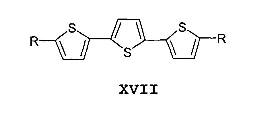
- In another general aspect of the present invention the calamitic n-type materials are selected from the group consisting of the structures XV to XVII:


- Advantageously, the discotic p-type materials are selected from the group consisting of the structures XVIII to XXII:

- Furthermore the calamitic p-type materials are selected from the group consisting of the structures XXIII to XXXII:


- In a particular aspect of the present invention, high optical anisotropy liquid mesogenic materials are selected from the group consisting of the structures XXXIII to XXXVIII:


- In another particular aspect of the present invention, a discotic material, soluble in high polarity solvents, is the structure XXXIX:

- In an additional particular aspect of the present invention, a discotic material insoluble in high polarity solvents is the structure XL:

- More precisely, the present invention discloses a method using the above mentioned molecules
- wherein "x" is the number of thiophene or vinylthiophene units and is between 2 and 6;
- wherein "M" can be one metal atom (Cu, Zn, Co, Pt, ...) or two atoms (Li2, H2);
- wherein "R" is an atom such as F, Cl, Br, I, H, ..., a functional group such as NH2, NO2, CN, SO3H, COOH, ... or their salts, an aliphatic, an oligoether moieties, or a combination of them, preceded by a heteroatom such as S, O, N, ..., and/or a semi-flexible function such as ester, amide, ..., and/or or a rigid function such as alkene, alkyne, phenyl,...;
- wherein "A" is C-R4 or N (nitrogen), and y is the number
of ethyleneoxy units in each chain.
- R2 is
- hydrogen (H) or deuterium (D)
- halogen (F, Cl, Br or I)
- nitro (NO2)
- nitryl (CN)
- R4 is
- ether (O-R3)
- ester (O-CO- R3 or CO-O- R3)
- ketone (CO-R3)
- alkyl (R3) with R1 and R3 being an alkyl group, branched or not, of 1 to 10 carbon atoms. The number of ethyleneoxy units y is fixed between 1 and 6.
- wherein M1 is a metal (zinc (Zn), copper (Cu), platinum (Pt), palladium (Pd)) or two protons (H2), and R5 is a branched aliphatic chain of 8 to 24 carbon atoms.
- Additionally, the invention discloses a discotic material insoluble in high polarity solvents is: 2, 9 (10), 16 (17), 23 (24)-Tetra(2-decyltetradecyloxy)-phthalocyanine XL (M1 is H2 ; R5 is 2-decyltetradecyl).
- Furthermore, the invention discloses a discotic material soluble in high polarity solvents is: 2, 3, 8, 9, 14, 15-hexa{2-[2-(2-methoxy-ethoxy)-ethoxy]-5, 6, 11, 12, 17, 18-hexaaza-trinaphthylene XXXIX (A is C-R4 ; R4 is H ; R1 is C2H4 ; R2 is O-CH3 ; y is 2)
- In practice, the deposited successive layers have a thickness from 1 nm to 2 µm each and are deposited by spin coating, doctor blading, zone casting, or the Langmuir-Blodgett technique.
- Fig.1 represents the schematic structure of one example of a bilayer device of the present invention.
- Fig.2 represents the schematic structure of a bilayer field effect transistor of the present invention.
- Fig.3 summarises some examples of n-type discotic liquid crystals that can be used in electronic devices according to the present invention. "R" can be composed, independently, by an atom (F, Cl, Br, I, H, ...), a functional group (NH2, NO2, CN, SO3H, COOH, ...) or their salts, or an aliphatic, or oligoether moieties, or a combination of them, preceded by an heteroatom (S, O, N, ...), and/or a semi-flexible function (ester, amide, ...), and/or or a rigid function (alkene, alkyne, phenyl, ...).
- Fig.4 summarises some examples of n-type calamitic liquid crystals that can be used in electronic devices according to the present invention. "x", the number of thiophene units, is taken between 2 and 6. "R" can be composed, independently, by an atom (F, Cl, Br, I, H, ...), a functional group (NH2, NO2, CN, SO3H, COOH, ...) or their salts, or an aliphatic, or oligoether moieties, or a combination of them, preceded by an heteroatom (S, O, N, ...), and/or a semi-flexible function (ester, amide, ...), and/or or a rigid function (alkene, alkyne, phenyl, ...).
- Fig.5 summarises some examples of p-type discotic liquid crystals that can be used in electronic devices according to the present invention. "M" can be one metal atom (Cu, Zn, Co, Pt, ...) or two atoms (Li2, H2). "R" can be composed, independently, by an atom (F, Cl, Br, I, H, ...), a functional group (NH2, NO2, CN, SO3H, COOH, ...) or their salts, or an aliphatic, or oligoether moieties, or a combination of them, preceded by an heteroatom (S, O, N, ...), and/or a semi-flexible function (ester, amide, ...), and/or or a rigid function (alkene, alkyne, phenyl, ...).
- Fig.6 summarises some examples of p-type calamitic liquid crystals that can be used in electronic devices according to the present invention. "R" can be composed, independently, by an atom (F, Cl, Br, I, H, ...), a functional group (NH2, NO2, CN, SO3H, COOH, ...) or their salts, or an aliphatic, or oligoether moieties, or a combination of them, preceded by an heteroatom (S, O, N, ...), and/or a semi-flexible function (ester, amide, ...), and/or or a rigid function (alkene, alkyne, phenyl, ...).
- Fig.7 summarises some examples of high optical anisotropy liquid crystals that can be used in LCDs according to the present invention. "R" can be composed, independently, by an atom (F, Cl, Br, I, H, ...), a functional group (NH2, NO2, CN, SO3H, COOH, ...) or their salts, or an aliphatic, or oligoether moieties, or a combination of them, preceded by an heteroatom (S, O, N, ...), and/or a semi-flexible function (ester, amide, ...), and/or or a rigid function (alkene, alkyne, phenyl, ...).
- Fig.8 represents the device structure of example 1.
- Fig.9 represents one of the discotic structure XXX, soluble in high polarity solvents, that can be used in the present invention.
- Fig.10 represents one of the discotic structure XXXI, insoluble in high polarity solvents, that can be used in the present invention.
- Fig.11 shows the comparison between the solid-state absorption spectra of an hexa-aza-trinaphthylene XXX soluble in acetone, and an acetone insoluble phthalocyanine derivative XXXI; and of the bilayer device obtained by spin coating according to the present invention.
- The present invention relates to a method for the manufacturing of multilayer mesogenic materials by use of solubility complementarities between the organic mesogenes to be deposited.
- On a
substrate 1, coated by one to four alignment and/orelectrode layers 2, is deposited a first solution with a first mesogenic material m1 dissolved in a first solvent S1, forming a first layer ofmesogenic material 3. A second layer is then added on the top of the firstmesogenic material 3, from a solution consisting in a second material m2 dissolved in a second solvent, this second solvent should not be able to solubilise the first material m1 to avoid the deterioration and/or the washing of the material m1 by said second solvent. This process leads to the formation of the second layer ofmesogenic material 4 and can be continued until the right number of layers is achieved. - According to the present invention, the last deposited layer should always be insoluble in the solvent of the next layer to be deposited.
- The
top layer 5 is then added. This layer comprises one to four alignment and/or electrode layers. - The
substrate 1 consists in a flat hard or flexible surface. Non-restrictive examples of such materials are glass, quartz, silica, silicon, mica, organic polymers [polyethylene (PE), polypropylene (PP), polybutadiene (PBD), polystyrene (PS), polyvinylchloride (PVC), polyurethanes (PU), polyethyleneterephthalate (PET), polymethacrylates (Plexiglas, ...), blends or copolymers of them, chemically and/or physically modified or not. These substrates are well known by those skilled in the art. - The
substrate 1 can be optionally coated with one to four electrode/alignment layers 2 with a thickness of 0.1 to 100 nm each. These layers align the material m1 of the first layer ofmesogens 3 in a certain direction and/or act simply as an electrode. - Typical materials for
electrode layers - In electronic components, the nature of the first mesogenic material m1 will be conditioned by the
layers 2. If the work-function of theelectrode 2 is low, the first mesogenic material m1 has to be a n-type semiconductor. Examples of such n-type semi-conductors are represented in Fig.3 and 4 and can be discotic liquid crystal derived from the hexaazatriphenylene I, hexaazatrinaphthylene II, dodecaazatrinaphthylene III, hexaazatriisooxanaphthene IV, hexaazatriisothianaphthene V, tricycloquinazoline VI, perylo[1,12-efg]isoindole-1,3-dione VII, tetraazatetrahydrocoronene-tetracarboxylic acid bisphenylimide VIII, terylene IX, quaterylene X, perylene bisamidine XIa XIb, perinone bisbenzimidazole XIIa XIIb, perylene XIII, pyrene XIV, ... aromatic cores, substituted with flexible side-chains; or calamitic liquid crystal derived from the 2,5-Diphenyl-pyrimidine XV, 2-Biphenyl-4-yl-5-phenyl-2,5-dihydro-[1,3,4]oxadiazole XVI, terthiophene XVII, ... substituted with flexible side-chains. - If the work-function of the
electrode 2 is high, the first mesogenic material m1 has to be a p-type semiconductor. Examples of such p-type semiconductors are represented in Fig. 5 and 6 and can be a discotic liquid crystal derived from the triphenylene XVIII, hexabenzocoronene XIX, phthalocyanine XX, porphyrin XXI, tetraazaporphyrin XXII, ... aromatic cores, substituted with flexible side-chains; or it can be a calamitic liquid crystal derived from naphthalene XXIII, anthracene XXIV, tetracene XXV, pentacene XXVI, Dithiadicyclopenta[b,i]anthracene XXVIIa XXVIIb, 2,6-Diphenylanthracene XXVIII, 1,4-Distyryl-benzene XXIX, 2-Phenylbenzothiazole XXX, oligothiophene XXXI, oligovinylthiophene XXXII, ... - The solvents S1 to Sj used to dissolve the first mesogenic material highly depends on the solubility characteristics of the first material. Representative solvents include, but are not intended to be limited to, aromatic and aliphatic hydrocarbons, haloaromatic and haloaliphatic hydrocarbons, water, ether, ester, keton, alcohol, amine, amide, or acid based solvents. Particularly preferred solvents are toluene, xylenes, chloroform, dichloromethane, hexane, water, methanol, ethanol, isopropanol, diethylether, acetone and acetic acid.
- Preferred methods for the depositing of the first mesogenic material m1 is solution based coating such as spin coating, doctor blading, Langmuir-Blodgett, zone-casting, or any variant of those. A particularly preferred method is the spin coating technique. The films are obtained by injecting the solution on the spinning substrate at 500 to 5000 rpm, with or without gradient of speed or acceleration. Spinning time can be from 2 to 300 seconds. The injection can be performed before or during spinning. The solution and the
substrate 1 can be independently heated up or cooled down at a temperature of -70°C to 250°C. The coating can be performed under air, argon, nitrogen, ... or in the presence of a solvent vapour. The thin film obtained can have from 1 nm to 2 µm of average thickness. The solvent of the mesogenic material m1 evaporates during the spinning operation. - The nature of the second mesogenic material m2 will depend on the nature of the
layer 3. In the case of PVCs, thelayer 4 has to be complementary with thelayer 3. If the material used in 3 is of n-type, the material of 4 has to show an electron donor character (p-type), and vice versa. Some examples of both families of semiconductors are given above. In the case of OLEDs, thelayer 4 will act as an electroluminescent layer. The material has to be both electrons and holes acceptor to be luminescent. Such a material can derive from the terylene IX, quaterylene X, perylene XIII, pyrene XIV, ... aromatic cores, substituted with flexible side-chains. - For certain applications (OLEDs, LCDs, ...), additional layers of mesogenic materials are requested. The materials composing the complementary layers have to be chosen according to the needs. According to the invention, those supplementary layers have to be deposited with a solvent that cannot dissolve the material composing the previous layer.
- In the case of some LCDs, mesogenic materials with high optical anisotropy are needed. Some examples of materials are given in Figure 7.
- When the desired mesogenic multilayer structure is achieved the electronic component/device can be optionally encapsulated.
- The preferred embodiments are disclosed by the following particularly contemplated combinations.
- 1. bilayer device comprising two layers of calamitic or discotic materials m1 and m2. Only one of both materials is soluble in hexane. The multilayer structure is achieved by spin coating the two layers on top of each other;
- 2. bilayer device comprising two layers of calamitic or discotic materials m1 and m2. Only one of both materials is soluble in water. The multilayer structure is achieved by spin coating the two layers on top of each other;
- 3. bilayer device comprising a first layer of calamitic material soluble in acetone and insoluble in toluene, and a second layer of discotic material soluble in toluene. The multilayer structure is achieved by spin coating the two layers on top of each other;
- 4. four-layers device comprising two layers of calamitic materials and two layers of discotic materials is made by a combining the processes of spin coating and Doctor-blading;
- 5. bilayer device comprising two layers of discotic materials that are crystalline at device working temperature. The multilayer structure is achieved by spin coating the two layers on top of each other.
-
- Proceeding from an 5, 6, 11, 12, 17, 18-hexaazatrinaphthylene (HATNA) or 1, 4, 5, 6, 7, 10, 11, 12, 13, 16, 17, 18-dodecaaza-trinaphthylene (DATNA) derivative of the structure XXXIX, soluble in high polarity solvents such as water, methanol, ethanol, acetone, toluene or chloroform; and a room temperature liquid crystalline tetrasubstituted phthalocyanine derivative of the structure XL, which is insoluble in said high polarity solvents.
- In one of the preferred embodiments of the invention, poly-aza-trinaphthylene derivatives of the structure XXXIX are defined as follows:wherein A is C-R4 or N (nitrogen), and y is the number of ethyleneoxy units in each chain.

- R2 is
- hydrogen (H) or deuterium (D)
- halogen (F, Cl, Br or I)
- nitro (NO2)
- nitryl (CN)
- R4 is
- ether (O-R3)
- ester (O-CO- R3 or CO-O- R3)
- ketone (CO-R3)
- alkyl (R3) with R1 and R3 being an alkyl group, branched or not, of 1 to 10 carbon atoms. The number of ethyleneoxy units y is fixed between 1 and 6.
-
- In another preferred embodiment of the invention, tetrasubstituted phthalocyanine derivatives of the structure XL are defined as follows:wherein M1 is a metal (zinc (Zn), copper (Cu), platinum (Pt), palladium (Pd)) or two protons (H2), and R5 is a branched aliphatic chain of 8 to 24 carbon atoms.

- In the general embodiment, illustrated in Fig. 1, spin coating is used for the film deposition.
- A solution of 0.1 to 50 gram per litre of the phthalocyanine derivative XL is made. The solvent is dichloromethane, chloroform, toluene, xylene, or hexane. In order to increase the solution concentration, the later can be heated up to reflux. The solution (hot or cold) is spin coated on a
substrate 1 consisting in a flat surface as defined above, coated with 50 nm of indium tin oxide (ITO) that acts as lowwork function electrode 2. The film thickness, regularity, and roughness is regulated by the general spinning conditions, the concentration of the solution and the nature of the solvent. - The spinning rate is generally chosen between 500 and 5000 rpm with or without gradient of speed or acceleration, and the spinning time is chosen between 2 and 300 seconds. Under these conditions, a
good quality film 3 can be obtained, with a thickness range of 5 to 500 nm. - A solution of 0.1 to 50 gram per litre of an hexaaza-trinaphthylene derivative XXXIX is made. In order to increase the solution concentration, the later can be heated up until reflux. The solution (hot or cold) is spin coated on the top of the
film 3, using a spinning rate of 500 to 5000 rpm with or without gradient of speed or acceleration, and a spinning time of 2 to 300 seconds. Under these conditions, agood quality film 4 can be obtained on the top of 3, with a thickness range of 5 to 500 nm. Thetop layer 5, preferably consisting in a metallic (calcium, silver, aluminium, ...) and/or inorganic salts (LiF, CsF, Li2O, ...) and/or organic (PEDOT-PSS, ...) electrode and/or in an aligning layer (PTFE, ...) is then coated. - Two solutions of low molecular weight semiconductors are made, using two different solvents. In the former, 15 mg of 2, 9 (10), 16 (17), 23 (24)-Tetra(2-decyltetradecyloxy)-phthalocyanine (M1 is H2 ; R5 is 2-decyltetradecyl) is dissolved in 1 mL of chloroform. The later is obtained by dissolving 20 mg of 2, 3, 8, 9, 14, 15-hexa{2-[2-(2-methoxy-ethoxy)-ethoxy]-5, 6, 11, 12, 17, 18-hexaazatrinaphthylene (A is C-R4 ; R4 is H ; R1 is C2H4 ; R2 is O-CH3 ; y is 2) in 1 mL of acetone.
A first layer of organic semiconductor is spin-coated on a quartz substrate (rotation speed: 1500 rpm; spinning time: 30 sec.). The second layer is then coated (rotation speed: 1500 rpm; spinning time: 30 sec.) on its top, forming two layers of small molecules semiconductors. The presence of the two materials in the final multilayer coating is proven by taking an UV-visible absorption spectrum. Fig. 11 shows the absorption spectrum of the bilayer device, in comparison with the pure materials solid-state spectra and their arithmetic sum. - Legend
- 1. substrate
- 2. first electrode layer (one to four layers of metal and/or metal oxide and/or organic material)
- 3. first layer of mesogenic material m1
- 4. second layer of mesogenic material m2
- 5. second electrode layer (one to four layers of metal and/or metal oxide and/or organic material)
- 6. gate electrode
- 7. insulating layer
- 8. alignment layers (optional)
- 9. drain electrode
- 10. source electrode
-
Claims (16)
- Method for the manufacturing of an electronic component comprising the deposition of a multilayer structure of the successive mesogenic materials m1, m2.., mj on a substrate (1) comprising the steps of:wherein the mesogenic material m (i-1) is insoluble in the solvent Si of the following mesogenic material mi in the manufacturing of the successive layers m1, m2.., mj to avoid the washing of the layer m (i-1) by the solvent Si. (i = 2 to j)dissolving of a mesogenic material m1,m2..,mj respectively in the solvents S1, S2.. Sj ;depositing a first layer of said first mesogenic material m1 dissolved in S1, on a substrate (1);depositing a second layer of said second mesogenic material m2 dissolved in S2, on said first layer of mesogenic material m1;depositing finally a supplementary layer of the mesogenic material mj dissolved in Sj, on a layer of mesogenic material m(j-1);
- The method of Claim 1 wherein the mesogenic materials m1, m2.., mj are selected from the group consisting of calamitic and/or discotic materials.
- The method of Claim 1 wherein said mesogenic materials m1, m2.., mj are in a crystalline phase or in a mesophase and in particular in a plastic crystalline phase, liquid crystalline phase or glass phase at processing or electronic device working temperatures.
- The method of Claim 1 wherein the solvents S1, S2.. Sj are selected from the group consisting of aromatic and aliphatic hydrocarbons, haloaromatic and haloaliphatic hydrocarbons, water, ether, ester, keton, alcohol, amine, amide, and acid based solvents.
- The method of Claim 2 wherein the discotic n-type materials are selected from the group consisting of the structures I to XIV:


- The method of Claim 2 wherein the calamitic n-type materials are selected from the group consisting of the structures XV to XVII:

- The method of Claim 2 wherein the discotic p-type materials are selected from the group consisting of the structures XVIII to XXII:

- The method of Claim 2 wherein the calamitic p-type materials are selected from the group consisting of the structures XXIII to XXXII:


- The method of Claim 2 wherein high optical anisotropy liquid mesogenic materials are selected from the group consisting of the structures XXXIII to XXXVIII:


- The method according to any of the preceding claims wherein a discotic material, soluble in high polarity solvents, is the structure XXXIX:

- The method according to any of the preceding claims wherein a discotic material insoluble in high polarity solvents is the structure XL:

- The method according to any of the preceding claimswherein "x" is the number of thiophene or vinylthiophene units and is between 2 and 6.wherein "M" can be one metal atom (Cu, Zn, Co, Pt, ...) or two atoms (Li2, H2).wherein "R" is an atom such as F, Cl, Br, I, H, ..., a functional group such as NH2, NO2, CN, SO3H, COOH, ... or their salts, an aliphatic, an oligoether moieties, or a combination of them, preceded by a heteroatom such as S, O, N, ..., and/or a semi-flexible function such as ester, amide, ..., and/or or a rigid function such as alkene, alkyne, phenyl,....wherein "A" is C-R4 or N (nitrogen), and y is the number of ethyleneoxy units in each chain.with R1 and R3 being an alkyl group, branched or not, of 1 to 10 carbon atoms. The number of ethyleneoxy units y is fixed between 1 and 6.R2 ishydrogen (H) or deuterium (D)halogen (F, Cl, Br or I)nitro (NO2)nitryl (CN)R4 isether (O-R3)ester (O-CO- R3 or CO-O- R3)ketone (CO-R3)alkyl (R3)wherein M1 is a metal (zinc (Zn), copper (Cu), platinum (Pt), palladium (Pd)) or two protons (H2), and R5 is a branched aliphatic chain of 8 to 24 carbon atoms.
- The method according to any of the preceding claims wherein a discotic material insoluble in high polarity solvents is: 2, 9 (10), 16 (17), 23 (24)-Tetra(2-decyltetradecyloxy)-phthalocyanine XL (M1 is H2 ; R5 is 2-decyltetradecyl).
- The method according to any of the preceding claims wherein a discotic material soluble in high polarity solvents is: 2, 3, 8, 9, 14, 15-hexa{2-[2-(2-methoxy-ethoxy)-ethoxy]-5, 6, 11, 12, 17, 18-hexaazatrinaphthylene XXXIX (A is C-R4 ; R4 is H ; R1 is C2H4 ; R2 is O-CH3 ; y is 2)
- The method according to any of the preceding claims wherein the deposited successive layers have a thickness from 1 nm to 2 µm each.
- The method of any of the preceding claims wherein said layers are deposited by spin coating, doctor blading, zone casting, or the Langmuir-Blodgett technique.
Priority Applications (2)
| Application Number | Priority Date | Filing Date | Title |
|---|---|---|---|
| EP04447034A EP1564827A1 (en) | 2004-02-10 | 2004-02-10 | Method for the manufacturing of multilayer mesogenic components |
| PCT/EP2005/000557 WO2005076384A1 (en) | 2004-02-10 | 2005-01-18 | Method for the manufacturing of multilayer mesogenic components |
Applications Claiming Priority (1)
| Application Number | Priority Date | Filing Date | Title |
|---|---|---|---|
| EP04447034A EP1564827A1 (en) | 2004-02-10 | 2004-02-10 | Method for the manufacturing of multilayer mesogenic components |
Publications (1)
| Publication Number | Publication Date |
|---|---|
| EP1564827A1 true EP1564827A1 (en) | 2005-08-17 |
Family
ID=34684831
Family Applications (1)
| Application Number | Title | Priority Date | Filing Date |
|---|---|---|---|
| EP04447034A Withdrawn EP1564827A1 (en) | 2004-02-10 | 2004-02-10 | Method for the manufacturing of multilayer mesogenic components |
Country Status (2)
| Country | Link |
|---|---|
| EP (1) | EP1564827A1 (en) |
| WO (1) | WO2005076384A1 (en) |
Cited By (2)
| Publication number | Priority date | Publication date | Assignee | Title |
|---|---|---|---|---|
| WO2007066098A1 (en) * | 2005-12-05 | 2007-06-14 | Cryscade Solar Limited | Organic solar cell |
| WO2007085810A1 (en) * | 2006-01-25 | 2007-08-02 | Kontrakt Technology Limited | Backlight polar organic light-emitting device |
Citations (2)
| Publication number | Priority date | Publication date | Assignee | Title |
|---|---|---|---|---|
| WO1999010939A2 (en) * | 1997-08-22 | 1999-03-04 | Koninklijke Philips Electronics N.V. | A method of manufacturing a field-effect transistor substantially consisting of organic materials |
| WO2001047043A1 (en) * | 1999-12-21 | 2001-06-28 | Plastic Logic Limited | Solution processed devices |
-
2004
- 2004-02-10 EP EP04447034A patent/EP1564827A1/en not_active Withdrawn
-
2005
- 2005-01-18 WO PCT/EP2005/000557 patent/WO2005076384A1/en active Application Filing
Patent Citations (2)
| Publication number | Priority date | Publication date | Assignee | Title |
|---|---|---|---|---|
| WO1999010939A2 (en) * | 1997-08-22 | 1999-03-04 | Koninklijke Philips Electronics N.V. | A method of manufacturing a field-effect transistor substantially consisting of organic materials |
| WO2001047043A1 (en) * | 1999-12-21 | 2001-06-28 | Plastic Logic Limited | Solution processed devices |
Non-Patent Citations (1)
| Title |
|---|
| L. SCHMIDT-MENDE ET AL.: "Self-Organized Discotic LIquid Crystals for high Efficiency Organic Photovoltaics", SCIENCE, vol. 293, 10 August 2001 (2001-08-10), pages 1119 - 1122, XP002279797 * |
Cited By (2)
| Publication number | Priority date | Publication date | Assignee | Title |
|---|---|---|---|---|
| WO2007066098A1 (en) * | 2005-12-05 | 2007-06-14 | Cryscade Solar Limited | Organic solar cell |
| WO2007085810A1 (en) * | 2006-01-25 | 2007-08-02 | Kontrakt Technology Limited | Backlight polar organic light-emitting device |
Also Published As
| Publication number | Publication date |
|---|---|
| WO2005076384A1 (en) | 2005-08-18 |
Similar Documents
| Publication | Publication Date | Title |
|---|---|---|
| Locklin et al. | Organic thin film transistors based on cyclohexyl-substituted organic semiconductors | |
| Lee et al. | Characteristics of solution‐processed small‐molecule organic films and light‐emitting diodes compared with their vacuum‐deposited counterparts | |
| Gsänger et al. | High-performance organic thin-film transistors of J-stacked squaraine dyes | |
| Cravino et al. | Triphenylamine− oligothiophene conjugated systems as organic semiconductors for opto-electronics | |
| US7037599B2 (en) | Organic light emitting diodes for production of polarized light | |
| US6649283B1 (en) | Polyimide layer comprising functional material, device employing the same and method of manufacturing same device | |
| Yang et al. | Effects of thin film processing on pentacene/C60 bilayer solar cell performance | |
| TW201217378A (en) | Nitrogenated aromatic compound, organic semiconductor material, and organic electronic device | |
| WO2005029605A1 (en) | Field effect type organic transistor and process for production thereof | |
| Sun et al. | Phthalimide–thiophene-based conjugated organic small molecules with high electron mobility | |
| Keuker-Baumann et al. | Absorption and luminescence spectra of electroluminescent liquid crystals with triphenylene, pyrene and perylene units | |
| Palilis et al. | Organic photovoltaic cells with high open circuit voltages based on pentacene derivatives | |
| Kongsabay et al. | An efficient solution-processable hybridized local and charge-transfer (HLCT)-based deep-red fluorescent emitter for simple structured non-doped OLED | |
| EP1722424A1 (en) | Method for the manufacturing of homeotropically aligned layer of discotic liquid crystals | |
| JP2017521395A (en) | N-fluoroalkyl substituted dibromonaphthalenediimides and their use as semiconductors | |
| CN101326652A (en) | Materials for organic thin film transistors | |
| TWI586634B (en) | Organic optoelectronic material and use thereof | |
| Kumar et al. | Functional pyrene–pyridine-integrated hole-transporting materials for solution-processed OLEDs with reduced efficiency roll-off | |
| Kippelen et al. | Liquid-crystal approaches to organic photovoltaics | |
| CN101384531A (en) | Liquid-crystalline styryl derivative, process for producing the same, and liquid-crystalline semiconductor element employing the same | |
| EP1564827A1 (en) | Method for the manufacturing of multilayer mesogenic components | |
| Pająk et al. | New thiophene imines acting as hole transporting materials in photovoltaic devices | |
| Sim et al. | Polymer binder assisted, solution processed cyanophenyl functionalized diketopyrrolopyrrole microwire for n-channel field-effect transistors | |
| Franca et al. | Delayed Fluorescence by Triplet–Triplet Annihilation from Columnar Liquid Crystal Films | |
| Yu et al. | Solution-processable donor-π-acceptor derivatives for high-performance electronic memristors |
Legal Events
| Date | Code | Title | Description |
|---|---|---|---|
| PUAI | Public reference made under article 153(3) epc to a published international application that has entered the european phase |
Free format text: ORIGINAL CODE: 0009012 |
|
| AK | Designated contracting states |
Kind code of ref document: A1 Designated state(s): AT BE BG CH CY CZ DE DK EE ES FI FR GB GR HU IE IT LI LU MC NL PT RO SE SI SK TR |
|
| AX | Request for extension of the european patent |
Extension state: AL LT LV MK |
|
| AKX | Designation fees paid | ||
| REG | Reference to a national code |
Ref country code: DE Ref legal event code: 8566 |
|
| STAA | Information on the status of an ep patent application or granted ep patent |
Free format text: STATUS: THE APPLICATION IS DEEMED TO BE WITHDRAWN |
|
| 18D | Application deemed to be withdrawn |
Effective date: 20060218 |