EP1564730A2 - Optical pickup apparatus - Google Patents
Optical pickup apparatus Download PDFInfo
- Publication number
- EP1564730A2 EP1564730A2 EP05002832A EP05002832A EP1564730A2 EP 1564730 A2 EP1564730 A2 EP 1564730A2 EP 05002832 A EP05002832 A EP 05002832A EP 05002832 A EP05002832 A EP 05002832A EP 1564730 A2 EP1564730 A2 EP 1564730A2
- Authority
- EP
- European Patent Office
- Prior art keywords
- optical
- laser beam
- axis
- laser
- flat plate
- Prior art date
- Legal status (The legal status is an assumption and is not a legal conclusion. Google has not performed a legal analysis and makes no representation as to the accuracy of the status listed.)
- Granted
Links
Images


Classifications
-
- G—PHYSICS
- G11—INFORMATION STORAGE
- G11B—INFORMATION STORAGE BASED ON RELATIVE MOVEMENT BETWEEN RECORD CARRIER AND TRANSDUCER
- G11B7/00—Recording or reproducing by optical means, e.g. recording using a thermal beam of optical radiation by modifying optical properties or the physical structure, reproducing using an optical beam at lower power by sensing optical properties; Record carriers therefor
- G11B7/12—Heads, e.g. forming of the optical beam spot or modulation of the optical beam
- G11B7/125—Optical beam sources therefor, e.g. laser control circuitry specially adapted for optical storage devices; Modulators, e.g. means for controlling the size or intensity of optical spots or optical traces
- G11B7/127—Lasers; Multiple laser arrays
- G11B7/1275—Two or more lasers having different wavelengths
-
- G—PHYSICS
- G11—INFORMATION STORAGE
- G11B—INFORMATION STORAGE BASED ON RELATIVE MOVEMENT BETWEEN RECORD CARRIER AND TRANSDUCER
- G11B7/00—Recording or reproducing by optical means, e.g. recording using a thermal beam of optical radiation by modifying optical properties or the physical structure, reproducing using an optical beam at lower power by sensing optical properties; Record carriers therefor
- G11B7/08—Disposition or mounting of heads or light sources relatively to record carriers
- G11B7/09—Disposition or mounting of heads or light sources relatively to record carriers with provision for moving the light beam or focus plane for the purpose of maintaining alignment of the light beam relative to the record carrier during transducing operation, e.g. to compensate for surface irregularities of the latter or for track following
- G11B7/095—Disposition or mounting of heads or light sources relatively to record carriers with provision for moving the light beam or focus plane for the purpose of maintaining alignment of the light beam relative to the record carrier during transducing operation, e.g. to compensate for surface irregularities of the latter or for track following specially adapted for discs, e.g. for compensation of eccentricity or wobble
- G11B7/0956—Disposition or mounting of heads or light sources relatively to record carriers with provision for moving the light beam or focus plane for the purpose of maintaining alignment of the light beam relative to the record carrier during transducing operation, e.g. to compensate for surface irregularities of the latter or for track following specially adapted for discs, e.g. for compensation of eccentricity or wobble to compensate for tilt, skew, warp or inclination of the disc, i.e. maintain the optical axis at right angles to the disc
-
- G—PHYSICS
- G11—INFORMATION STORAGE
- G11B—INFORMATION STORAGE BASED ON RELATIVE MOVEMENT BETWEEN RECORD CARRIER AND TRANSDUCER
- G11B7/00—Recording or reproducing by optical means, e.g. recording using a thermal beam of optical radiation by modifying optical properties or the physical structure, reproducing using an optical beam at lower power by sensing optical properties; Record carriers therefor
- G11B7/12—Heads, e.g. forming of the optical beam spot or modulation of the optical beam
- G11B7/135—Means for guiding the beam from the source to the record carrier or from the record carrier to the detector
- G11B7/1392—Means for controlling the beam wavefront, e.g. for correction of aberration
- G11B7/13922—Means for controlling the beam wavefront, e.g. for correction of aberration passive
-
- G—PHYSICS
- G11—INFORMATION STORAGE
- G11B—INFORMATION STORAGE BASED ON RELATIVE MOVEMENT BETWEEN RECORD CARRIER AND TRANSDUCER
- G11B7/00—Recording or reproducing by optical means, e.g. recording using a thermal beam of optical radiation by modifying optical properties or the physical structure, reproducing using an optical beam at lower power by sensing optical properties; Record carriers therefor
- G11B2007/0003—Recording, reproducing or erasing systems characterised by the structure or type of the carrier
- G11B2007/0006—Recording, reproducing or erasing systems characterised by the structure or type of the carrier adapted for scanning different types of carrier, e.g. CD & DVD
Definitions
- the present invention relates to an optical pickup apparatus for respectively recording and reproducing information respectively to and from optical disks having different board thicknesses of DVD (Digital Versatile Disk), CD (Compact Disk) or the like, particularly relates to an optical pickup apparatus capable of providing excellent spot light of a beam of laser light eliminating astigmatism and comma aberration.
- DVD Digital Versatile Disk
- CD Compact Disk
- a beam A of laser light emitted from a laser diode 11 is made to transmit a dichroic prism 13 and a deflecting beam splitter 14, further, a beam B emitted from a laser diode 12 is refracted by the dichroic prism 13 to coincide with an optical axis of the beam A, refracted in a direction orthogonal to an information recording face of an optical disk 21 to constitute a parallel beam by a collimator lens 16, deflected from elliptically polarized light to linearly polarized light by a quarter-wave prism 17 and is converged into spot light of the beam of laser light to the optical disk 21 by an object lens 18, and reflected light thereof is refracted in a direction of an optical detecting element 20 by the deflecting beam splitter 14 and is detected by the optical detecting element 20 via a cylindrical lens 19.
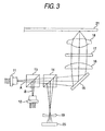
- a beam A of laser light emitted from a laser diode 31 is refracted to transmit by the parallel flat plate half mirrors 33, 34 arranged by angles orthogonal to an optical axis (in the drawing, the parallel flat plate half mirrors 33, 34 are shown simplifiedly two-dimensionally), further, a beam of laser light emitted from a laser diode 32 is refracted by the parallel flat plate half mirror 34 to coincide with the optical axis of the beam A of laser light, refracted by a total reflection mirror 35 in a direction orthogonal to an information recording face of an optical disk 40 to constitute a parallel beam by a collimator lens 36, deflected from elliptically polarized light to linearly polarized light by a quarter-wave plate 37 and is converged to spot light of the beam of laser light to the optical disk 40 by an object lens 38, and reflected light thereof is refracted in a direction of the optical detecting element 39 by the parallel flat plate half mirror 33 and is detected by the optical detecting element 39.
- a first parallel flat plate half mirror is arranged relative to an optical axis of Z axis of a beam of laser light emitted from one laser diode of two laser diodes having different wave lengths by being inclined around Y axis by an angle q
- a second parallel flat plate half mirror having a plate thickness the same as that of the first parallel flat plate half mirror is arranged by being inclined around X axis by an angle q
- the beam of laser light emitted from the one laser diode is successively refracted to transmit the first and the second parallel flat plate half mirrors
- the laser beam emitted from other laser beam diode is reflected by the second parallel flat plate half mirror to coincide the optical axes of the beams of laser light emitted from the two laser diodes having the different wave lengths (refer to, for example, JP-A-2001-006205).
- an inclination adjusting member is brought into contact with a lens, and by conducting electricity to a solenoid coil provided at a movable support member and a magnet provided at a fixed member in a state of bringing the inclination adjusting member into contact with the lens, the movable support member is displaced and an inclination of the lens is adjusted by pressing the lens to the inclination adjusting member (refer, for example, Japanese Patent Publication No. 3392904).
- first laser light from a first laser diode is reflected by a parallel flat plate half mirror, a reflected beam of the first laser light is converged by a converging lens, the converged beam of first laser light is shaped by a beam shaping prism and is converged to a first optical disk in correspondence with the first laser light, laser light from a second laser diode transmitted through a parallel flat plate half mirror is provided with astigmatism, second laser light from the second laser diode is converged to a second optical disk in correspondence with the second laser light, and astigmatism generated in passing a beam of the second light through the beam shaping prism is reduced (refer to, for example, JP-A-2001-344801).
- beams of respective laser light emitted from laser diodes for emitting two or more of beams of laser light having different wave lengths are converged by an object lens
- beams of respective laser light reflected by an optical disk and passing through an object lens are detected by an optical detecting element
- positions of returning the beams of respective laser light emitted from the laser diodes on optical paths between the laser diodes and the optical detecting element are made to coincide with each other at a light receiving face of the optical detecting element
- comma aberration is corrected by a hologram optical element (refer to, for example, JP-A-2003-317302).
- the first parallel flat plate half mirror is arranged to incline by the angle ⁇ relative to the optical axis of Z axis of the beam of laser light emitted from the one laser diode of the two laser diodes having different wave lengths
- the second parallel flat plate half mirror having the plate thickness the same as that of the first parallel flat plate half mirror is arranged to incline by the angle ⁇ around X axis
- the beam of laser light emitted from the one laser diode is successively refracted to transmit the first and the second parallel flat plate half mirrors
- the laser beam emitted from the other laser diode is reflected by the second parallel flat plate half mirror, thereby, the optical axes of the beams of laser light emitted from the two laser diodes having the different wave lengths can coincide with each other, however, it is difficult to eliminate astigmatism and comma aberration.
- the inclination adjusting member is brought into contact with the lens, in the state of bringing the inclination adjusting member into contact with the lens, by conducting electricity to the solenoid coil provided at the movable supporting member and the magnet provided at the fixed member, the movable supporting member is displaced, and the inclination of the lens can be adjusted by pressing the lens to the inclination adjusting member, however, the next configuration does not realize an optical pickup apparatus at low cost by reducing cost by a small number of pieces of parts.
- the first laser beam from the first laser diode is reflected by the parallel flat plate half mirror, the reflected beam of the first laser light is converged by the converging lens, the converged beam of first laser light is shaped by the beam shaping prism and converged to the first optical disk in correspondence with the first laser light, predetermined astigmatism is provided to the laser light from the second laser diode transmitting the parallel flat plate half mirror, the second laser beam from the second laser diode is converged to the second optical disk in correspondence with the second laser light, and astigmatism generated in passing the second laser light through the beam shaping prism can be reduced, however, similar to the above-described, the configuration does not realize an optical pickup apparatus at low cost by reducing cost by a small number of pieces of parts.
- the beams of respective laser light emitted from the laser diodes for emitting two or more of laser beams having the different wave lengths are converged by the object lens, the beams of respective laser light reflected by the optical disk and passing through the object lens is detected by the optical detecting element, the positions of returning the beams of respective laser light emitted from the laser diodes on the optical paths between the laser diodes and the optical detecting element are made to coincide with each other at the light receiving face of the optical detecting element, and comma aberration can be corrected by the hologram optical element, however, the hologram optical element needs to use, and the configuration does not realize an optical pickup apparatus at low cost.
- the invention has been carried out in view of the above-described problems of the background arts and it is an object thereof to provide an optical pickup apparatus capable of providing excellent spot light of a beam of laser light reducing cost by a small number of parts without using an expensive optical part and without deteriorating a function of the optical pickup apparatus and eliminating astigmatism and comma aberration.
- an optical pickup apparatus including: a first laser diode that emits a first laser beam having a first wave length; a second laser diode that emits a second laser beam having a second wave length that is different from the first wave length; a first optical element arranged on an optical axis of the first laser beam for refracting and transmitting the first laser beam therethrough, the first optical element being rotated by a first angle around a first axis orthogonal to the optical axis of the first laser beam and having a first refractive index; a second optical element arranged on the optical axis of the first laser beam that is transmitted through the first optical element for refracting and transmitting the first laser beam therethrough, and arranged on an optical axis of the second laser beam for refracting the second laser beam to coincide the optical axis of the second laser beam with the optical axis of the first laser beam, the second optical element being arranged at a position separated from the first optical element by a
- an optical pickup apparatus including: a first laser diode that emits a first laser beam having a first wave length; a second laser diode that emits a second laser beam having a second wave length that is different from the first wave length; a first optical element arranged on an optical axis of the first laser beam for refracting and transmitting the first laser beam therethrough, the first optical element being rotated by a first angle around a first axis orthogonal to the optical axis of the first laser beam and having a first refractive index; a second optical element arranged on the optical axis of the first laser beam that is transmitted through the first optical element for refracting and transmitting the first laser beam therethrough, and arranged on an optical axis of the second laser beam for refracting the second laser beam to coincide the optical axis of the second laser beam with the optical axis of the first laser beam, the second optical element being arranged at a position separated from the first optical element by a
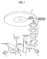
- Fig 1 is a perspective view showing a configuration of an optical pickup apparatus according to a first embodiment of the invention
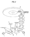
- Fig.2 is a perspective view showing a configuration of an optical pickup apparatus according to a second embodiment of the invention.
- the optical pickup apparatus includes two of a laser diode 1 and a laser diode 2 for emitting beams of laser light respectively having different wave lengths.
- a laser disk 10 is CD
- a beam A of laser light having a wave length of 790nm emitted from the laser diode 1 is converged to an information recording face of the optical disk 10 via an optical system
- information is recorded and reproduced to and from the optical disk 10
- reflected light of laser light reflected by the information recording face of the optical disk 10 is detected by an optical detecting element 9 and the information recorded to the optical disk 10 is read.
- the optical disk 10 is DVD
- a beam B of laser light having a wave length of 660nm emitted from the laser diode 2 is converged to the information recording face of the optical disk 10 via the optical system, information is recorded and reproduced to and from the optical disk 10, reflected light of laser light reflected by the information recording face of the optical disk 10 is detected by the optical detecting element 9 and information recorded to the optical disk 10 is read.
- the beam A of laser light having the wave lengths of 790nm emitted from the laser diode 1 is refracted to transmit a parallel flat plate half mirror 3a and a parallel flat plate half mirror 4 and is refracted in a direction orthogonal to the information recording face of the optical disk 10 by a total reflection mirror 5.
- the beam A of laser light refracted by the total reflection mirror 5 is made to constitute a parallel beam by a collimator lens 6 having a focal length of 20.05mm, and deflected from elliptically polarized light to linearly polarized light by a quarter-wave plate 7, and a beam of laser light deflected to the linearly polarized light is converged by an object lens 8 having a focal length of 3.05mm and a numerical aperture of 0.51 to the information recording face of the optical disk 10 having a thickness of 1.2mm, that is, to a position at a depth of 1.2mm of an inner face CD.
- reflected light of laser light reflected by the information recording face of the optical disk 10 of CD is returned in a reverse direction through the optical system of the object lens 8, the quarter-wave plate 7, the collimator lens 6, the total reflection mirror 5 and the parallel flat plate half mirror 4 and refracted in a direction of the optical detecting element 9 by the parallel flat plate half mirror 3a, the reflected light from the information recording face of the optical disk 10 of CD is detected by the optical detecting element 9 and information recorded to the information recording face of CD is read.
- the tilt angle correcting actuator 100 includes a supporting section and an actuating section.
- the supporting section includes four wires 101 that support the object lens 8 to be twistable in a tilting direction.
- the actuating section includes: a plurality of magnets 102 provided on a movable unit 103 in which the optical system including the object lens 8 is provided; and a plurality of coils (tracking coils 104 and focusing coils 105) provided on a fixed unit 106.
- Fig. 6 shows a top view of the tilt angle correcting actuator 100.
- the focusing coils 105 includes four focusing coils 105a, 105b, 105c and 105d.
- the focusing coils 105a and 105c are provided at one side of the movable unit 103 with respect to the tracking direction, and the focusing coils 105b and 105d are provided at the other side of the movable unit 103.
- the focusing coils 105a, 105c and the focusing coils 105b, 105d are activated in opposite phase.
- the focusing coils 105a, 105b, 105c and 105d are activated in the same phase.
- the tilt angle correcting actuator 100 is configured to be a type of a so-called moving magnet type.
- the tilt angle correcting actuator 100 serves as a tilt angle correcting unit that corrects a tilt angle of an optical system including the first and the second optical elements and cancels a comma aberration generated in a radial direction of an optical disk.
- the laser diode 2 is arranged such that the beam B of laser light having the wave length of 660nm emitted from the laser diode 2 is refracted by the parallel flat plate half mirror 4 to coincide with the optical axis of the beam A of laser light emitted from the laser diode 1.
- the beam B of laser light emitted from the laser diode 2 is refracted by the parallel flat plate half mirror 4 and is refracted in a direction orthogonal to the information recording face of the optical disk 10 by the total reflection mirror 5.
- the beam B of laser light refracted by the total reflection mirror 5 is made to constitute a parallel beam by the collimator lens 6 and deflected from elliptically polarized light to linearly polarized light by the quarter-wave plate 7 and a beam of laser light deflected to linearly polarized light is converged by the object lens 8 to the information recording face of the optical disk 10 of DVD having the thickness of 1.2mm, that is, a position at a depth of 0.6mm of an inner face of DVD.
- reflected light of laser light reflected by the information recording face of the optical disk 10 of DVD is returned in a reverse direction through an optical system of the object lens 8, the quarter-wave plate 7, the collimator lens 6, the total reflection mirror 5, and the parallel flat plate half mirror 4 and is refracted in a direction of the optical detecting element 9 by the parallel flat plate half mirror 3a, reflected light from the information recording face of the optical disk 10 of DVD is detected by the optical detecting element 9 and information recorded to the information recording face of DVD is read. Further, the beam B of laser light emitted from the laser diode 2 does not transmit through the parallel flat plate half mirror 4 and therefore, aberration is not generated.
- a parallel flat plate half mirror 3b is used in place of the parallel flat plate half mirror 3a according to the first embodiment. Further, constituent elements the same as those shown in Fig.1 are attached with the same notations and an explanation thereof will be omitted.
- the beam A of laser light having the wave length of 790nm emitted from the laser diode 1 is refracted to transmit the parallel flat plate half mirror 3b and the parallel flat plate half mirror 4 and is refracted in the direction orthogonal to the information recording face of the optical disk 10 by the total reflection mirror 5.
- the beam A of laser light refracted by the total reflection mirror 5 is made to constitute the parallel beam by the collimator lens 6 and deflected from elliptically polarized light to linearly polarized light by the quarter-wave plate 7 and the beam of laser light deflected to linearly polarized light is converged to the information recording face of the optical disk 10 having the thickness of 1.2mm, that is, to the position at the depth of 1.2mm of the inner face of CD by the object lens 8.
- the reflected light of laser light reflected by the information recording face of the optical disk 10 of CD is returned in the reverse direction through the optical system of the object lens 8, the quarter-wave plate 7, the collimator lens 6, the total reflection mirror 5 and the parallel flat plate half mirror 4 and is refracted in the direction of the optical detecting element 9 by the parallel flat plate half mirror 3b and reflected light from the information recording face of the optical disk 10 of CD is detected by the optical detecting element 9 and information recorded to the information recording face of CD is read.
- the laser diode 2 is arranged such that the beam B of laser light having the wave length of 660nm emitted from the laser diode 2 is refracted by the parallel flat plate half mirror 4 to coincide with the optical axis of the beam A of laser light emitted from the laser diode 1.
- the beam B of laser light emitted from the laser diode 2 is refracted by the parallel flat plate half mirror 4 and refracted in the direction orthogonal to the information recording face of the optical disk 10 by the total reflection mirror 5.
- the beam B of laser light refracted by the total reflection mirror 5 is made to constitute the parallel beam by the collimator lens 6 and deflected from elliptically polarized light to linearly polarized light by the quarter-wave plate 7, and a beam of laser light deflected to linearly polarized light is converged to the information recording face of the optical disk 10 of DVD having the thickness of 1.2mm, that is, to the position at the depth of 0.6mm of the inner face of DVD by the object lens 8.
- reflected light of laser light reflected by the information recording face of the optical disk 10 of DVD is returned in the reverse direction through the optical system of the object lens 8, the quarter-wave plate 7, the collimator lens 6, the total reflection mirror 5 and the parallel flat plate half mirror 4 and refracted in the direction of the optical detecting element 9 by the parallel flat plate half mirror 3b, and reflected light from the information recording face of the optical disk 10 of DVD is detected by the optical detecting element 9 and information recorded to the information recording face of DVD is read. Further, the beam B of laser light emitted from the laser diode 2 does not transmit through the parallel flat plate half mirror 4 and therefore, aberration is not generated.
- arranging the parallel flat plate half mirror 4 of BK7 having the thickness of 2.5mm at the position on the optical axis of the beam A of laser light separated from the parallel flat plate half mirror 3b by the distance of 8mm by being rotated in the counterclockwise direction around y axis by the angle of ⁇ 2 45°
- the tilt angle of the optical axis of the lens system comprising the collimator lens 6, the quarter-wave plate 7 and the object lens 8 of the optical pickup apparatus, or the tilt angle of the optical axis of the total of the optical pickup apparatus by the tilt angle correcting actuator
- the invention is not limited thereto but can be modified or improved within a normal range of knowledge of the skilled person.
- an explanation has been given of canceling astigmatism of the beam of laser light refracted to transmit the two parallel flat plate half mirrors by adjusting the thicknesses and the angles of the two parallel flat plate half mirrors of the optical glass material BK7 and arranging the two parallel flat plate half mirrors at the positions on the optical axis of the beam of laser light separated from each other by the predetermined distance, even when using two parallel flat plate half mirrors of other optical glass material having a different refractive index, by pertinently adjusting a separated distance, thicknesses and angles, astigmatism of the beam of laser light refracted to transmit the two parallel flat plate half mirrors can be cancelled.
Landscapes
- Physics & Mathematics (AREA)
- Optics & Photonics (AREA)
- Optical Head (AREA)
Abstract
Description
Claims (10)
- An optical pickup apparatus comprising:wherein the first and the second optical elements are formed to have same thickness, anda first laser diode that emits a first laser beam having a first wave length;a second laser diode that emits a second laser beam having a second wave length that is different from the first wave length;a first optical element arranged on an optical axis of the first laser beam for refracting and transmitting the first laser beam therethrough, the first optical element being rotated by a first angle around a first axis orthogonal to the optical axis of the first laser beam and having a first refractive index;a second optical element arranged on the optical axis of the first laser beam that is transmitted through the first optical element for refracting and transmitting the first laser beam therethrough, and arranged on an optical axis of the second laser beam for refracting the second laser beam to coincide the optical axis of the second laser beam with the optical axis of the first laser beam, the second optical element being arranged at a position separated from the first optical element by a predetermined distance on the optical axis of the first laser beam, being rotated by a second angle around a second axis orthogonal to the optical axis of the first laser beam and the first axis, and having a second refractive index that cancels an astigmatism of the first laser beam; anda tilt angle correcting unit that corrects a tilt angle of an optical system including the first and the second optical elements and cancels a comma aberration generated in a radial direction of an optical disk,
wherein the first and the second optical elements are made of a same optical material. - An optical pickup apparatus comprising:a first laser diode that emits a first laser beam having a first wave length;a second laser diode that emits a second laser beam having a second wave length that is different from the first wave length;a first optical element arranged on an optical axis of the first laser beam for refracting and transmitting the first laser beam therethrough, the first optical element being rotated by a first angle around a first axis orthogonal to the optical axis of the first laser beam and having a first refractive index;a second optical element arranged on the optical axis of the first laser beam that is transmitted through the first optical element for refracting and transmitting the first laser beam therethrough, and arranged on an optical axis of the second laser beam for refracting the second laser beam to coincide the optical axis of the second laser beam with the optical axis of the first laser beam, the second optical element being arranged at a position separated from the first optical element by a predetermined distance on the optical axis of the first laser beam, being rotated by a second angle around a second axis orthogonal to the optical axis of the first laser beam and the first axis, and having a second refractive index that cancels an astigmatism of the first laser beam; anda tilt angle correcting unit that corrects a tilt angle of an optical system including the first and the second optical elements and cancels a comma aberration generated in a radial direction of an optical disk.
- The optical pickup apparatus according to claim 2, wherein the first optical element includes a parallel flat plate half mirror.
- The optical pickup apparatus according to claim 2, wherein the first optical element includes a parallel flat plate half mirror.
- The optical pickup apparatus according to claim 2, wherein the first and the second optical elements are formed to have same thickness.
- The optical pickup apparatus according to claim 2, wherein the first angle and the second angle are configured to have same value.
- The optical pickup apparatus according to claim 2, wherein the first and the second optical elements are made of a same optical material.
- The optical pickup apparatus according to claim 7, wherein the first and the second optical elements are made of an optical glass material BK7.
- The optical pickup apparatus according to claim 2, wherein the first optical element includes a parallel flat plate half mirror of an optical glass material BK7 having a thickness of 2.5mm arranged by being rotated by an angle of 43.6° around the first axis, and
wherein the second optical element includes a parallel flat plate half mirror of the optical glass material BK7 having a thickness of 2.5mm arranged to be separated from the first optical element by a distance of 8mm on the optical axis of the beam of the first laser beam by being rotated by an angle of 45° around the second axis. - The optical pickup apparatus according to claim 2, wherein the first optical element includes a parallel flat plate half mirror of an optical glass material BK7 having a thickness of 2.45mm arranged by being rotated by an angle of 45° around the first axis, and
wherein the second optical element includes a parallel flat plate half mirror of the optical glass material BK7 having a thickness of 2.5mm arranged to be separated from the first optical element by a distance of 8mm on the optical axis of the beam of the first laser light by being rotated by an angle of 45° around the second axis.
Applications Claiming Priority (2)
| Application Number | Priority Date | Filing Date | Title |
|---|---|---|---|
| JP2004032922 | 2004-02-10 | ||
| JP2004032922A JP4058638B2 (en) | 2004-02-10 | 2004-02-10 | Optical pickup device |
Publications (3)
| Publication Number | Publication Date |
|---|---|
| EP1564730A2 true EP1564730A2 (en) | 2005-08-17 |
| EP1564730A3 EP1564730A3 (en) | 2007-01-31 |
| EP1564730B1 EP1564730B1 (en) | 2009-06-24 |
Family
ID=34697867
Family Applications (1)
| Application Number | Title | Priority Date | Filing Date |
|---|---|---|---|
| EP05002832A Expired - Lifetime EP1564730B1 (en) | 2004-02-10 | 2005-02-10 | Optical pickup apparatus |
Country Status (5)
| Country | Link |
|---|---|
| US (1) | US7417937B2 (en) |
| EP (1) | EP1564730B1 (en) |
| JP (1) | JP4058638B2 (en) |
| CN (1) | CN100426392C (en) |
| DE (1) | DE602005015044D1 (en) |
Cited By (1)
| Publication number | Priority date | Publication date | Assignee | Title |
|---|---|---|---|---|
| WO2008114231A1 (en) * | 2007-03-22 | 2008-09-25 | Koninklijke Philips Electronics N.V. | Optical apparatus |
Families Citing this family (9)
| Publication number | Priority date | Publication date | Assignee | Title |
|---|---|---|---|---|
| JP2007072087A (en) * | 2005-09-06 | 2007-03-22 | Fujinon Sano Kk | Optical element and optical pickup |
| US7848020B2 (en) * | 2006-06-02 | 2010-12-07 | Jds Uniphase Corporation | Thin-film design for positive and/or negative C-plate |
| EP1892543A1 (en) | 2006-08-23 | 2008-02-27 | JDS Uniphase Corporation | Cartesian polarizers utilizing photo-aligned liquid crystals |
| JP2008059644A (en) * | 2006-08-30 | 2008-03-13 | Hitachi Media Electoronics Co Ltd | Optical pickup device and optical disk device including the same |
| JP4840167B2 (en) * | 2007-01-31 | 2011-12-21 | 船井電機株式会社 | Optical disk device |
| JP4989302B2 (en) * | 2007-05-10 | 2012-08-01 | Hoya株式会社 | Optical pickup optical system assembly method |
| JP2008305525A (en) * | 2007-06-11 | 2008-12-18 | Sony Corp | Optical pickup and optical disk apparatus |
| US20090190463A1 (en) * | 2008-01-30 | 2009-07-30 | Jds Uniphase Corporation, | Optical pick-up unit with two-mirror phase shifter |
| JP2015056469A (en) * | 2013-09-11 | 2015-03-23 | 昭和オプトロニクス株式会社 | Diode laser module wavelength controlled by external resonator |
Family Cites Families (18)
| Publication number | Priority date | Publication date | Assignee | Title |
|---|---|---|---|---|
| JPS60111058U (en) | 1983-12-28 | 1985-07-27 | ソニー株式会社 | semiconductor laser equipment |
| JPS61236035A (en) * | 1985-04-09 | 1986-10-21 | Sony Corp | Optical head |
| JPS62102437A (en) | 1985-10-29 | 1987-05-12 | Mitsubishi Electric Corp | Optical head device |
| JPH06162549A (en) | 1992-11-13 | 1994-06-10 | Omron Corp | Optical head device |
| EP0602732A3 (en) | 1992-12-17 | 1995-09-27 | Philips Electronics Nv | Optical system with astigmatism compensation. |
| JP3392904B2 (en) | 1993-03-19 | 2003-03-31 | ペンタックス株式会社 | Lens tilt adjusting method and device |
| KR20000009844A (en) * | 1998-07-29 | 2000-02-15 | 사까이 히로시 | Optical pickup |
| KR100295102B1 (en) * | 1998-07-29 | 2001-07-12 | 이형도 | Optical pickup |
| JP2000311371A (en) | 1999-04-28 | 2000-11-07 | Ricoh Co Ltd | Optical pickup device |
| EP1178474A1 (en) * | 1999-05-11 | 2002-02-06 | Matsushita Electric Industrial Co., Ltd. | Optical head |
| JP2001006205A (en) | 1999-06-21 | 2001-01-12 | Akai Electric Co Ltd | Optical pickup device |
| KR100348883B1 (en) * | 1999-09-03 | 2002-08-17 | 엘지전자주식회사 | Optical pick up for suppressing astigmatism |
| JP2001344801A (en) | 2000-05-31 | 2001-12-14 | Matsushita Electric Ind Co Ltd | Optical pickup |
| US6496453B2 (en) * | 2000-03-27 | 2002-12-17 | Matsushita Electric Industrial Co., Ltd. | Optical pickup |
| JP3890941B2 (en) * | 2001-10-02 | 2007-03-07 | 日本電気株式会社 | Objective lens drive |
| WO2003032029A1 (en) * | 2001-10-09 | 2003-04-17 | Koninklijke Philips Electronics N.V. | Optical devices |
| JP2003123305A (en) | 2001-10-10 | 2003-04-25 | Nec Corp | Optical head device |
| JP2003317302A (en) | 2002-04-25 | 2003-11-07 | Sony Corp | Optical head and optical disk device |
-
2004
- 2004-02-10 JP JP2004032922A patent/JP4058638B2/en not_active Expired - Fee Related
-
2005
- 2005-02-09 US US11/053,664 patent/US7417937B2/en not_active Expired - Fee Related
- 2005-02-10 EP EP05002832A patent/EP1564730B1/en not_active Expired - Lifetime
- 2005-02-10 DE DE602005015044T patent/DE602005015044D1/en not_active Expired - Lifetime
- 2005-02-16 CN CNB200510009023XA patent/CN100426392C/en not_active Expired - Fee Related
Cited By (1)
| Publication number | Priority date | Publication date | Assignee | Title |
|---|---|---|---|---|
| WO2008114231A1 (en) * | 2007-03-22 | 2008-09-25 | Koninklijke Philips Electronics N.V. | Optical apparatus |
Also Published As
| Publication number | Publication date |
|---|---|
| US7417937B2 (en) | 2008-08-26 |
| DE602005015044D1 (en) | 2009-08-06 |
| JP2005228365A (en) | 2005-08-25 |
| US20050180292A1 (en) | 2005-08-18 |
| EP1564730A3 (en) | 2007-01-31 |
| CN100426392C (en) | 2008-10-15 |
| EP1564730B1 (en) | 2009-06-24 |
| CN1655257A (en) | 2005-08-17 |
| JP4058638B2 (en) | 2008-03-12 |
Similar Documents
| Publication | Publication Date | Title |
|---|---|---|
| US5892749A (en) | Optical head device for reading two optical disks | |
| EP1564730B1 (en) | Optical pickup apparatus | |
| EP1083554A2 (en) | Optical pickup apparatus with reduced astigmatic aberration | |
| JPH11110768A (en) | Optical pickup device | |
| US5809000A (en) | Optical pickup system for reading optical disks of different thicknesses | |
| US20040120242A1 (en) | Optical pickup using two-wavelength light source module | |
| JP2001034991A (en) | Lens, optical pickup device, and lens tilt detection method | |
| US8355309B2 (en) | Optical pickup device | |
| KR20040068176A (en) | Optical scanning device | |
| US8130624B2 (en) | Optical head device for forming light spot on disc-shaped information medium | |
| EP0468685B1 (en) | Optical information recording-reproducing apparatus | |
| US8279724B2 (en) | Optical pickup | |
| US7570547B2 (en) | Objective lens unit and optical pickup device | |
| JPH11110767A (en) | Optical pickup device | |
| JP2008243257A (en) | Optical pickup | |
| US20060245335A1 (en) | Optical head and information recording/reproducing apparatus | |
| KR100244179B1 (en) | optical pickup device pick-up | |
| JPH08329518A (en) | Optical pickup | |
| US20090073857A1 (en) | Optical pickup apparatus | |
| JP4358643B2 (en) | Optical head | |
| JPH10247338A (en) | Optical pickup device | |
| JP4383139B2 (en) | Optical pickup and optical disk apparatus | |
| JPH10149562A (en) | Optical pickup and optical disk device | |
| JP2002230821A (en) | Information recording / reproducing device | |
| JPH033127A (en) | optical head |
Legal Events
| Date | Code | Title | Description |
|---|---|---|---|
| PUAI | Public reference made under article 153(3) epc to a published international application that has entered the european phase |
Free format text: ORIGINAL CODE: 0009012 |
|
| AK | Designated contracting states |
Kind code of ref document: A2 Designated state(s): AT BE BG CH CY CZ DE DK EE ES FI FR GB GR HU IE IS IT LI LT LU MC NL PL PT RO SE SI SK TR |
|
| AX | Request for extension of the european patent |
Extension state: AL BA HR LV MK YU |
|
| PUAL | Search report despatched |
Free format text: ORIGINAL CODE: 0009013 |
|
| AK | Designated contracting states |
Kind code of ref document: A3 Designated state(s): AT BE BG CH CY CZ DE DK EE ES FI FR GB GR HU IE IS IT LI LT LU MC NL PL PT RO SE SI SK TR |
|
| AX | Request for extension of the european patent |
Extension state: AL BA HR LV MK YU |
|
| 17P | Request for examination filed |
Effective date: 20070713 |
|
| 17Q | First examination report despatched |
Effective date: 20070828 |
|
| AKX | Designation fees paid |
Designated state(s): DE FR GB |
|
| GRAP | Despatch of communication of intention to grant a patent |
Free format text: ORIGINAL CODE: EPIDOSNIGR1 |
|
| GRAS | Grant fee paid |
Free format text: ORIGINAL CODE: EPIDOSNIGR3 |
|
| GRAA | (expected) grant |
Free format text: ORIGINAL CODE: 0009210 |
|
| AK | Designated contracting states |
Kind code of ref document: B1 Designated state(s): DE FR GB |
|
| REG | Reference to a national code |
Ref country code: GB Ref legal event code: FG4D |
|
| REF | Corresponds to: |
Ref document number: 602005015044 Country of ref document: DE Date of ref document: 20090806 Kind code of ref document: P |
|
| PLBE | No opposition filed within time limit |
Free format text: ORIGINAL CODE: 0009261 |
|
| STAA | Information on the status of an ep patent application or granted ep patent |
Free format text: STATUS: NO OPPOSITION FILED WITHIN TIME LIMIT |
|
| 26N | No opposition filed |
Effective date: 20100325 |
|
| REG | Reference to a national code |
Ref country code: FR Ref legal event code: PLFP Year of fee payment: 12 |
|
| PGFP | Annual fee paid to national office [announced via postgrant information from national office to epo] |
Ref country code: DE Payment date: 20160202 Year of fee payment: 12 |
|
| PGFP | Annual fee paid to national office [announced via postgrant information from national office to epo] |
Ref country code: FR Payment date: 20160108 Year of fee payment: 12 Ref country code: GB Payment date: 20160210 Year of fee payment: 12 |
|
| REG | Reference to a national code |
Ref country code: DE Ref legal event code: R119 Ref document number: 602005015044 Country of ref document: DE |
|
| GBPC | Gb: european patent ceased through non-payment of renewal fee |
Effective date: 20170210 |
|
| REG | Reference to a national code |
Ref country code: FR Ref legal event code: ST Effective date: 20171031 |
|
| PG25 | Lapsed in a contracting state [announced via postgrant information from national office to epo] |
Ref country code: FR Free format text: LAPSE BECAUSE OF NON-PAYMENT OF DUE FEES Effective date: 20170228 Ref country code: DE Free format text: LAPSE BECAUSE OF NON-PAYMENT OF DUE FEES Effective date: 20170901 |
|
| PG25 | Lapsed in a contracting state [announced via postgrant information from national office to epo] |
Ref country code: GB Free format text: LAPSE BECAUSE OF NON-PAYMENT OF DUE FEES Effective date: 20170210 |