EP1564631A1 - Display control device, display control program, and display control method - Google Patents
Display control device, display control program, and display control method Download PDFInfo
- Publication number
- EP1564631A1 EP1564631A1 EP02808098A EP02808098A EP1564631A1 EP 1564631 A1 EP1564631 A1 EP 1564631A1 EP 02808098 A EP02808098 A EP 02808098A EP 02808098 A EP02808098 A EP 02808098A EP 1564631 A1 EP1564631 A1 EP 1564631A1
- Authority
- EP
- European Patent Office
- Prior art keywords
- display
- screen
- line
- drawn
- area
- Prior art date
- Legal status (The legal status is an assumption and is not a legal conclusion. Google has not performed a legal analysis and makes no representation as to the accuracy of the status listed.)
- Withdrawn
Links
Images

Classifications
-
- G—PHYSICS
- G06—COMPUTING OR CALCULATING; COUNTING
- G06F—ELECTRIC DIGITAL DATA PROCESSING
- G06F3/00—Input arrangements for transferring data to be processed into a form capable of being handled by the computer; Output arrangements for transferring data from processing unit to output unit, e.g. interface arrangements
- G06F3/01—Input arrangements or combined input and output arrangements for interaction between user and computer
- G06F3/048—Interaction techniques based on graphical user interfaces [GUI]
- G06F3/0487—Interaction techniques based on graphical user interfaces [GUI] using specific features provided by the input device, e.g. functions controlled by the rotation of a mouse with dual sensing arrangements, or of the nature of the input device, e.g. tap gestures based on pressure sensed by a digitiser
- G06F3/0488—Interaction techniques based on graphical user interfaces [GUI] using specific features provided by the input device, e.g. functions controlled by the rotation of a mouse with dual sensing arrangements, or of the nature of the input device, e.g. tap gestures based on pressure sensed by a digitiser using a touch-screen or digitiser, e.g. input of commands through traced gestures
-
- G—PHYSICS
- G06—COMPUTING OR CALCULATING; COUNTING
- G06F—ELECTRIC DIGITAL DATA PROCESSING
- G06F3/00—Input arrangements for transferring data to be processed into a form capable of being handled by the computer; Output arrangements for transferring data from processing unit to output unit, e.g. interface arrangements
- G06F3/01—Input arrangements or combined input and output arrangements for interaction between user and computer
- G06F3/048—Interaction techniques based on graphical user interfaces [GUI]
- G06F3/0484—Interaction techniques based on graphical user interfaces [GUI] for the control of specific functions or operations, e.g. selecting or manipulating an object, an image or a displayed text element, setting a parameter value or selecting a range
- G06F3/0485—Scrolling or panning
Definitions
- Display control device display control program, and display control method
- the present invention relates to a display control device, a display control program, and a display control method that controls a display device that displays a screen area wider than the width of the screen display area. More particularly, the present invention relates to a display control device, a display control program, and a display control method that allows the displayed screen to change by a simple operation even when a pen input device is used as the input device, and yet maintain the screen clarity.
- a pen input device is generally used as an input device of a portable information terminal. Unlike a keyboard or a mouse, the pen input device is simple to operate and is portable and is best suited for the portable information terminal. In recent years, the pen input device is also used as the input device for tablet type personal computers with emphasis on simplicity of operations and portability.
- the location of the pen input device cannot be determined unless the pen input devices touches the display screen. Moreover, since touching the display screen with the pen input device is considered as an instruction for the computer, it cannot function as an instruction for the display screen to scroll.
- a scroll bar or a scroll button needs to be included in the display area to scroll the display screen by means of the pen input device, thereby causing loss of space in the display area, as well as affecting the clarity.
- the display screen cannot be scrolled for applications not compatible with the software, or when the scroll bar or the scroll buttons themselves are outside the display area of the display device even in a compatible software.
- a display control device controls a display device capable of displaying a screen area wider than a screen display area and includes an identifying unit that detects an input in an input receiving area provided near the screen display area; and a display shift instruction unit that instructs the display device to change the display in the screen display area based on a result of detection by the identifying unit.
- a computer program causes a computer to controls a display device capable of displaying a screen area wider than a screen display area, and causes the computer to execute detecting an input in an input receiving area provided near the screen display area; and instructing the display device to change the display in the screen display area based on a result of detection at the detecting.
- a display control method controls a display device capable of displaying a screen area wider than a screen display area and includes detecting an input in an input receiving area provided near the screen display area; and instructing the display device to change the display in the screen display area based on a result of detection at the detecting.
- an input is detected in the input receiving area provided around the screen display area, and the display device is instructed to shift the screen that is displayed in the screen display area based on the input detection.
- the screen that is displayed can be shifted using a simple operation even if a pen input device is used as the input device, and yet the screen clarity is maintained.
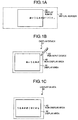
- Fig. 1A, Fig. 1B, and Fig. 1C are drawings illustrating a concept of a scrolling operation of a display screen according to a first embodiment of the present invention
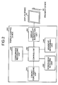
- Fig. 2 is a functional block diagram of a display control device according to the first embodiment
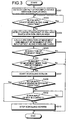
- Fig. 3 is a flowchart of a process of the display control device according to the first embodiment
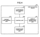
- Fig. 4 is a functional block diagram of a display control device according to a second embodiment of the present invention
- Fig. 5 is a flowchart of a process of the display control device according to the second embodiment
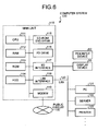
- Fig. 6 is a drawing of a computer system that executes a control program according to the first and second embodiments.
- FIG. 1 is a drawing of the concept of the scrolling operation of the display screen according to the first embodiment.
- Fig. 1B when a user drags the pen input device 60 from left to right on the right side of the non-display area 40, the display screen scrolls to the left as shown in Fig. 1C.
- the display screen scrolls to the right, when dragged from bottom to top above the non-display area 40, the display screen scrolls downward, and when dragged from top to bottom below the non-display area 40 the display screen scrolls upward.
- the display device 50 in addition to the display area 30, the display device 50 includes a pen input receiving area surrounding the display area 30, the margin between the pen input receiving area and the display area 30 comprising the non-display area 40, and the display screen is made to scroll by means of the pen input device 60 by dragging it in the non-display area 40 based on where the line is drawn as well as the direction in which the line is drawn, thereby enabling the scrolling of the screen by means of the pen input device 60.
- Fig. 2 is a functional block diagram of the display control device according to the first embodiment.
- a display control device 200 includes a contact point sensing unit 210, a coordinates recognizing unit 220, a screen edge detecting unit 230, a movement determining unit 240, a display screen shift instruction unit 250, and a control unit 260.
- the contact point sensing unit 210 detects when the pen input device 60 comes in contact with the pen input receiving area, that is, either the display area 30 or the non-display area 40 surrounding the display area 30.
- the pen input receiving area is covered by a resistor film or an electromagnetic inductor in the form of a thin film.
- the contact of the pen input device 60 is detected from the change in the resistance of the resistor film or the change in the capacitance of the electromagnetic inductor.
- the coordinates recognizing unit 220 recognizes the coordinates of the contact point detected by the contact point sensing unit 210 when the pen input device 60 touches the pen input receiving area. Further, the coordinates are recognized by means of a coordinate system in which the top left corner is taken as the origin (0,0) of the coordinates, with X-axis along the right and Y-axis downwards.
- the screen edge detecting unit 230 detects whether the contact point is in the non-display area 40 based on the coordinates of the contact point recognized by the coordinates recognizing unit 220 when the pen input device 60 touches the pen input receiving area. The detection by the screen edge detecting unit 230 of the contact point in the non-display area 40 when the pen input device 60 touches the pen input receiving area starts the display screen control of the display control device 200.
- the movement determining unit 240 calculates the direction of movement and the amount of movement of the pen input device 60 with the aid of the track from the contact start point of the pen input device 60 in the non-display area 40 detected by the screen edge detecting unit 230, and determines whether to start the scrolling of the display screen based on the calculated direction of the movement, the amount of the movement as well as the contact location of the pen input device.
- the movement determining unit 240 calculates the direction of movement and the amount of movement in the direction of the X-axis as well as the Y-axis of the pen input device 60 from the coordinates of the contact start point and the contact end point of the pen input device 60. If the calculated amount of movement is more than a predetermined value, and if the combination of the direction of movement and the contact location of the pen input device 60 is right, the movement determining unit 240 determines to start the scrolling of the display screen in the direction of movement of the pen input device 60.
- the combination of the contact location and the direction of movement of the pen input device 60 is right if the contact location is the non-display area 40 to the right of the display area 30 and the direction of movement is from left to right. Similarly, the combination is right if the contact location is the non-display area 40 to the left of the display area 30 and the direction of movement is from right to left. The combination is right if the contact location is the non-display area 40 above the display area 30 and the direction of movement is from bottom to top. Similarly, the combination is right if the contact location is the non-display area 40 below the display area 30 and the direction of movement is from top to bottom. There is no need to determine whether the combination of the contact location and the direction of movement is right.
- the display screen scrolls to the left. If the contact location is the non-display area 40 to the left of the display area 30, the display screen scrolls to the right. If the contact location is the non-display area 40 above the display area 30, the display screen scrolls downward, and if the contact location is the non-display area 40 below the display area 30, the display screen scrolls upward.
- the contact end point of the pen input device 60 is that point where the pen input device 60 stops moving.
- the movement determining unit 240 determines that the scrolling of the display screen should be stopped either when the pen input device 60 starts moving in the opposite direction or is removed from the non-display area 40.
- the movement determining unit 240 determines to start or stop the scrolling of the display screen based on which part of the non-display area 40 is touched by the pen input device 60, the direction of movement of the pen input device 60, and the amount of movement of the pen input device 60. Consequently, the display screen can be scrolled by operating the pen input device 60.
- the display screen shift instruction unit 250 gives instructions to the display device 50 to start scrolling or stop scrolling the display screen in a specified direction based on what the movement determining unit 240 determines.
- the control unit 260 controls the entire display control device 200. To be specific, the control unit 260 makes the display control device 200 function as one device by shifting control and enabling data exchange between the rest of the functional units.
- FIG. 3 is a flowchart of the display control process of the display control device 200 according to the first embodiment.
- the screen edge detecting unit 230 detects the contact of the pen input device 60 with the non-display area 40, thereby causing the display control device 200 to start the display control process (step S301).
- the screen edge detecting unit 230 senses the movement of the pen input device 60 when the pen input device 60 is moving along the same direction (step S302).
- the movement determining unit 240 detects the contact end point of the pen input device 60 (step S303), calculates the direction of movement, and the amount of movement of the pen input device 60 along X-axis and along Y-axis (step S304), and determines whether the combination of the contact location in the non-display area 40 and the direction of movement of the pen input device 60 is right (step S305). If the combination of the contact location in the non-display area 40 and the direction of movement of the pen input device 60 is not right, the display control process ends there.
- the movement determining unit 240 determines whether the amount of movement of the pen input device 60 is more than a predetermined value (step S306). If the amount of movement of the pen input device 60 is not more than the predetermined value, the display control process ends there. If the amount of movement of the pen input device 60 is more than the predetermined value, the movement determining unit 240 instructs the display device 50 to start scrolling the display screen via the display screen shift instruction unit 250 (step S307).
- the movement determining unit 240 determines whether the pen input device 60 has moved in the opposite direction (step S308), and if the pen input device 60 has not moved in the opposite direction, further determines whether the pen input device 60 is in contact with the non-display area 40 (step S309). If the pen input device 60 is in contact with the non-display area 40, the movement determining unit 240 determines that the pen input device 60 is in contact with the non-display area 40.
- the movement determining unit 240 instructs the display device 50 to stop scrolling the display screen via the display screen shift instruction unit 250, thereby ending the display control process (step S310).
- the screen edge detecting unit 230 detects when the pen input device 60 touches the non-display area 40, the movement determining unit 240 determines to start or stop the scrolling of the display screen in the specific direction based on the contact location of the pen input device 60 in the non-display area 40, the direction of movement of the pen input device 60, and the amount of movement of the pen input device 60.
- the display screen shift instruction unit 250 instructs the display device 50 to start or stop the scrolling of the display screen in the specific direction.
- the display screen can be easily scrolled by means of the pen input device 60.
- the non-display area 40 entirely surrounds the display area 30, and the scrolling direction of the display screen is determined based on the location and the direction in which the pen input device 60 is dragged in the non-display area 40.
- the present invention can be similarly applied in such a way that the non-display area 40 only partially surrounds the display area 30.
- the non-display area 40 may be provided to the right of the display area 30, and the scrolling direction of the display screen is determined based only on the direction in which the pen input device 60 is dragged in the non-display area.
- the scrolling of the display screen by dragging the pen input device 60 in the non-display area 40 is explained in the first embodiment.
- operations other than dragging the pen input device 60 in the display area can be used to give instructions to the display control device for shifting the display screen.
- the display control device that shifts the display screen when the pen input device 60 merely touches the non-display area is explained in a second embodiment.
- FIG. 4 is a functional block diagram of the display control device according to the second embodiment.
- the parts that are the same as or equivalent to the parts in Fig. 2 are assigned the same reference numerals, and are not explained in detail.
- a display control device 400 includes the contact point sensing unit 210, the coordinates recognizing unit 220, a screen edge detecting unit 430, a display screen shift instruction unit 450, and the control unit 260.
- the screen edge detecting unit 430 determines the contact location when the pen input device 60 touches the non-display area 40, and determines the scrolling direction of the display screen of the display device 50 based on the contact location. To be specific, the screen edge detecting unit 430 determines whether the contact location of the pen input device 60 is to the left, to the right, to the top, or to the bottom of the display area 30. If the contact location is to the right of the display area 30, the screen edge detecting unit 430 determines that the display screen should be shifted to the left by a predetermined distance. If the contact location is to the left of the display area 30, the screen edge detecting unit 430 determines that the display screen should be shifted to the right by a predetermined distance.
- the screen edge detecting unit 430 determines that the display screen should be shifted downward by a predetermined distance, and if the contact location is below the display area 30, the screen edge detecting unit 430 determines that the display screen should be shifted upward by a predetermined distance.
- the screen edge detecting unit 430 determines the contact location of the pen input device 60 in the non-display area 40, and determines the direction in which the display screen is to be shifted by a predetermined distance based on the contact location. Consequently, the display screen can be easily shifted by means of the pen input device 60.
- the display screen shift instruction unit 450 gives instructions to the display device 50 pertaining to the direction of shift and the amount of shift of the display screen based on what the screen edge detecting unit 430 determines. However, the display screen shift instruction unit 450 does not instruct the display device 50 to scroll the display screen, but to display the screen that is moved by a predetermined distance.
- FIG. 5 is a flowchart of the display control process of the display control device 400 according to the second embodiment.
- the display control device 400 determines whether the detected contact point is to the left, right, above, or below of the display area 30 (step S502), and determines the direction of shift of the display screen.
- step S503 If the contact point is above the display area 30, the display screen shift instruction unit 450 instructs the display device 50 to shift the display screen downward by a predetermined distance (step S503). If the contact point is below the display area 30, the display screen shift instruction unit 450 instructs the display device 50 to shift the display screen upward by a predetermined distance (step S504). If the contact point is to the left of the display area 30, the display screen shift instruction unit 450 instructs the display device 50 to shift the display screen to the right by a predetermined distance (step S505). If the contact point is to the right of the display area 30, the display screen shift instruction unit 450 instructs the display device 50 to shift the display screen to the left by a predetermined distance (step S506), thereby ending the process.
- the screen edge detecting unit 430 determines the direction of shift of the display screen based on the contact location of the pen input device in the non-display area 40, and the display screen shift instruction unit 450 instructs the display device 50 to shift the display screen by a predetermined distance in the determined direction. Consequently, the display screen can be easily shifted by means of the pen input device 60.
- Displaying a part of the virtual screen 10 by dragging the pen input device 60 in the non-display area or touching the non-display area with the pen input device 60 is explained in the first embodiment and the second embodiment.
- the present invention can be similarly applied in such a way that when a specific symbol or shape is drawn in the non-display area by means of the pen input device 60 toggles the display screen between full view of the virtual screen 10 with reduced display quality and a partial view of the virtual screen 10 with uncompromised display quality.
- the display control device was explained in the first embodiment and the second embodiment. However, the configuration of the display control device can be provided in software form and a display control program that includes similar functions can be formulated. A computer system that executes the display control program is explained next.
- Fig. 6 is a drawing of a computer system that executes the display control program according to the first and second embodiments.
- a computer system 100 includes a main unit 110, the display device 50 that displays a display screen according to instructions from the main unit 110, and the pen input device 60 that inputs various types of information into the computer system 100.
- the display area of the display device 50 and the area around the display area are covered with a resistor film that receives the input from the pen input device 60.
- the main unit 110 includes a Central Processing Unit (CPU) 111, a Random Access Memory (RAM) 112, a Read Only Memory (ROM) 113, a Hard Disk Drive (HDD) 114, a Compact Disk-Read Only Memory/Digital Versatile Disk (CD-ROM/DVD) drive 115, a Floppy Disk (FD) drive 116, an Input/Output (I/O) interface 117, a Local Area Network (LAN) interface 118, and a modem 119.
- the computer system 100 is connected to another computer system (such as a personal computer) 121, a server 122, and a printer 123 etc. via a LAN 120 connected to the LAN interface 118, and to a public circuit 130 via the modem 119.
- the display control program executed by the computer system 100 is stored in portable storage media such as floppy disk, CD-ROM, DVD disk, magneto optic disk, IC card etc., or the database of the server 122 connected to the computer system 100 via the LAN interface 118, or the database of the computer system 121, or the data base of other computer system connected to the computer system 100 via the public circuit 130.
- the main unit 110 reads the display control program stored these storage media and databases, and installs the display control program in the computer system 100.
- the installed display control program is stored in the HDD 114 and executed by the CPU 111 by means of the RAM 112, the ROM 113 etc.
- an input is detected in the input receiving area provided around the screen display area, and the display device is instructed to shift the screen that is displayed in the screen display area based on the input detection.
- the screen that is displayed can be shifted using a simple operation even if a pen input device is used as the input device, and yet the screen clarity is maintained.
- the display control device, the display control program, and the display control method according to the present invention is useful in tablet type personal computers with emphasis on simplicity of operation and portability.
Landscapes
- Engineering & Computer Science (AREA)
- General Engineering & Computer Science (AREA)
- Theoretical Computer Science (AREA)
- Human Computer Interaction (AREA)
- Physics & Mathematics (AREA)
- General Physics & Mathematics (AREA)
- User Interface Of Digital Computer (AREA)
- Position Input By Displaying (AREA)
Abstract
Description
However, the present invention can be similarly applied in such a way that the
Claims (20)
- A display control device that controls a display device capable of displaying a screen area wider than a screen display area, comprising:an identifying unit that detects an input in an input receiving area provided near the screen display area; anda display shift instruction unit that instructs the display device to change the display in the screen display area based on a result of detection by the identifying unit.
- The display control device according to claim 1, wherein the input receiving area is provided around the screen display area.
- The display control device according to claim 1 or 2, wherein the identifying unit identifies a shape drawn in the input receiving area, and the display shift instruction unit instructs the display device to change the display in the screen display area based on the shape identified by the identifying unit.
- The display control device according to claim 3, wherein the identifying unit identifies as a line any line drawn from left to right, or from right to left, or from bottom to top, or from top to bottom, and the display shift instruction unit instructs the display device to shift the display screen towards left if the line is drawn from left to right, towards right if the line is drawn from right to left, downward if the line is drawn from bottom to top, and upward if the line is drawn from top to bottom.
- The display control device according to claim 4, wherein the identifying unit identifies the line drawn from left to right in the input receiving area to the right of the screen display area, the line drawn from right to left in the input receiving area to the left of the screen display area, the line drawn from bottom to top in the input receiving area above the screen display area, and the line drawn from top to bottom in the input receiving area below the screen display area, and the display shift instruction unit instructs the display device to scroll to the left if the line identified by the identifying unit is drawn from left to right, to the right if the line identified by the identifying unit is drawn from right to left, downward if the line identified by the identifying unit is drawn from bottom to top, and upward if the line identified by the identifying unit is drawn from top to bottom.
- the display control device according to claim 4 or 5, wherein the identifying unit identifies the line as either the line drawn from left to right or the line from right to left if a shift amount horizontally is more than a predetermined value, and as either the line drawn from bottom to top or the line drawn from top to bottom if the shift amount vertically is more than the predetermined value, the shift amount being a difference between a start point and an end point of the line drawn in the input receiving area.
- The display control device according to claim 2, wherein the shape input on the right side of, left side of, above, and below the screen display area is identified by the identifying unit as a point, and the display shift instruction unit instructs the display device to shift the display screen by a predetermined amount to the left if the point identified by the identifying unit is input in the input receiving area to the right of the screen display area, to the right if the point identified by the identifying unit is input in the input receiving area to the left of the screen display area, downward if the point identified by the identifying is input in the input receiving area above the screen display area, and upward if the point identified by the identifying unit is input in the input receiving area below the screen display area.
- The display control device according to claim 3, wherein the identifying unit further identifies, besides the line, another predetermined shape drawn in the input receiving area, and the display shift instruction unit instructs the display device to toggle between a full screen with reduced display quality and a partial screen with uncompromised display quality when the identifying unit identifies the predetermined shape.
- A computer program that causes a computer to controls a display device capable of displaying a screen area wider than a screen display area, the computer program causing the computer to execute:detecting an input in an input receiving area provided near the screen display area; andinstructing the display device to change the display in the screen display area based on a result of detection at the detecting.
- The computer program according to claim 9, wherein the input receiving area is provided around the screen display area.
- The computer program according to claim 9 or 10, wherein the detecting includes detecting a shape drawn in the input receiving area, and the instructing includes instructing the display device to change the display in the screen display area based on the shape detected at the detecting.
- The computer program according to claim 11, wherein the detecting includes detecting as a line any line drawn from left to right, or from right to left, or from bottom to top, or from top to bottom, and the instructing includes instructing the display device to shift the display screen towards left if the line is drawn from left to right, towards right if the line is drawn from right to left, downward if the line is drawn from bottom to top, and upward if the line is drawn from top to bottom.
- The computer program according to claim 12, wherein the detecting includes detecting the line drawn from left to right in the input receiving area to the right of the screen display area, the line drawn from right to left in the input receiving area to the left of the screen display area, the line drawn from bottom to top in the input receiving area above the screen display area, and the line drawn from top to bottom in the input receiving area below the screen display area, and the instructing includes instructing the display device to scroll to the left if the line detected at the detecting is drawn from left to right, to the right if the line detected at the detecting is drawn from right to left, downward if the line detected at the detecting is drawn from bottom to top, and upward if the line detected at the detecting is drawn from top to bottom.
- The computer program according to claim 12 or 13, wherein the detecting includes detecting the line as either the line drawn from left to right or the line from right to left if a shift amount horizontally is more than a predetermined value, and as either the line drawn from bottom to top or the line drawn from top to bottom if the shift amount vertically is more than the predetermined value, the shift amount being a difference between a start point and an end point of the line drawn in the input receiving area.
- The computer program according to claim 10, wherein the shape input on the right side of, left side of, above, and below the screen display area is detected at the detecting as a point, and the instructing includes instructing the display device to shift the display screen by a predetermined amount to the left if the point detected at the detecting is input in the input receiving area to the right of the screen display area, to the right if the point detected at the detecting is input in the input receiving area to the left of the screen display area, downward if the point identified by the identifying is input in the input receiving area above the screen display area, and upward if the point detected at the detecting is input in the input receiving area below the screen display area.
- The computer program according to claim 11, wherein the detecting includes detecting, besides the line, another predetermined shape drawn in the input receiving area, and the instructing includes instructing the display device to toggle between a full screen with reduced display quality and a partial screen with uncompromised display quality when the predetermined shape is detected at the detecting.
- A display control method of controlling a display device capable of displaying a screen area wider than a screen display area, comprising:detecting an input in an input receiving area provided near the screen display area; andinstructing the display device to change the display in the screen display area based on a result of detection at the detecting.
- The display control method according to claim 17, wherein the detecting includes detecting a shape drawn in the input receiving area, and the instructing includes instructing the display device to change the display in the screen display area based on the shape detected at the detecting.
- The display control method according to claim 18, wherein the shape input on the right side of, left side of, above, and below the screen display area is detected at the detecting as a point, and the instructing includes instructing the display device to shift the display screen by a predetermined amount to the left if the point detected at the detecting is input in the input receiving area to the right of the screen display area, to the right if the point detected at the detecting is input in the input receiving area to the left of the screen display area, downward if the point identified by the identifying is input in the input receiving area above the screen display area, and upward if the point detected at the detecting is input in the input receiving area below the screen display area.
- The display control method according to claim 18, wherein the detecting includes detecting, besides the line, another predetermined shape drawn in the input receiving area, and the instructing includes instructing the display device to toggle between a full screen with reduced display quality and a partial screen with uncompromised display quality when the predetermined shape is detected at the detecting.
Applications Claiming Priority (1)
| Application Number | Priority Date | Filing Date | Title |
|---|---|---|---|
| PCT/JP2002/011519 WO2004042547A1 (en) | 2002-11-05 | 2002-11-05 | Display control device, display control program, and display control method |
Publications (2)
| Publication Number | Publication Date |
|---|---|
| EP1564631A1 true EP1564631A1 (en) | 2005-08-17 |
| EP1564631A4 EP1564631A4 (en) | 2008-12-31 |
Family
ID=32310226
Family Applications (1)
| Application Number | Title | Priority Date | Filing Date |
|---|---|---|---|
| EP02808098A Withdrawn EP1564631A4 (en) | 2002-11-05 | 2002-11-05 | DISPLAY CONTROL DEVICE, DISPLAY CONTROL PROGRAM, AND DISPLAY CONTROL METHOD |
Country Status (3)
| Country | Link |
|---|---|
| EP (1) | EP1564631A4 (en) |
| JP (1) | JPWO2004042547A1 (en) |
| WO (1) | WO2004042547A1 (en) |
Cited By (3)
| Publication number | Priority date | Publication date | Assignee | Title |
|---|---|---|---|---|
| EP2175353A1 (en) * | 2008-10-07 | 2010-04-14 | Research In Motion Limited | Portable electronic device and method of controlling same |
| US8619041B2 (en) | 2008-10-07 | 2013-12-31 | Blackberry Limited | Portable electronic device and method of controlling same |
| EP2770418A1 (en) * | 2013-02-25 | 2014-08-27 | Samsung Electronics Co., Ltd | Electronic apparatus comprising a touch screen and method of controlling the same |
Families Citing this family (3)
| Publication number | Priority date | Publication date | Assignee | Title |
|---|---|---|---|---|
| JP4579106B2 (en) * | 2005-09-05 | 2010-11-10 | 株式会社メイクソフトウェア | PHOTOGRAPHING APPARATUS, PHOTOGRAPHING APPARATUS CONTROL METHOD, AND PHOTOGRAPHING APPARATUS CONTROL PROGRAM |
| US7919646B2 (en) | 2006-07-14 | 2011-04-05 | Invista North America S.A R.L. | Hydrocyanation of 2-pentenenitrile |
| JP6716519B2 (en) * | 2017-10-05 | 2020-07-01 | シャープ株式会社 | Display device and display method |
Family Cites Families (2)
| Publication number | Priority date | Publication date | Assignee | Title |
|---|---|---|---|---|
| JP2002016969A (en) * | 2000-06-29 | 2002-01-18 | Matsushita Electric Ind Co Ltd | How to display the receiving screen |
| JP5039911B2 (en) * | 2000-10-11 | 2012-10-03 | インターナショナル・ビジネス・マシーンズ・コーポレーション | Data processing device, input / output device, touch panel control method, storage medium, and program transmission device |
-
2002
- 2002-11-05 WO PCT/JP2002/011519 patent/WO2004042547A1/en not_active Ceased
- 2002-11-05 JP JP2004549556A patent/JPWO2004042547A1/en not_active Withdrawn
- 2002-11-05 EP EP02808098A patent/EP1564631A4/en not_active Withdrawn
Cited By (3)
| Publication number | Priority date | Publication date | Assignee | Title |
|---|---|---|---|---|
| EP2175353A1 (en) * | 2008-10-07 | 2010-04-14 | Research In Motion Limited | Portable electronic device and method of controlling same |
| US8619041B2 (en) | 2008-10-07 | 2013-12-31 | Blackberry Limited | Portable electronic device and method of controlling same |
| EP2770418A1 (en) * | 2013-02-25 | 2014-08-27 | Samsung Electronics Co., Ltd | Electronic apparatus comprising a touch screen and method of controlling the same |
Also Published As
| Publication number | Publication date |
|---|---|
| WO2004042547A1 (en) | 2004-05-21 |
| EP1564631A4 (en) | 2008-12-31 |
| JPWO2004042547A1 (en) | 2006-03-09 |
Similar Documents
| Publication | Publication Date | Title |
|---|---|---|
| US20050168441A1 (en) | Display control device, display control method, computer product | |
| US20230325073A1 (en) | Information processing apparatus, information processing method, and program | |
| CN101714056B (en) | Information processing apparatus, information processing method | |
| CN1661538B (en) | Pointing device for terminal with touch screen and method of using same | |
| CN102934067B (en) | Information processing system, operation input equipment, information processor, information processing method | |
| EP1912112B1 (en) | Storage medium storing input position processing program, and input position processing device | |
| EP1536316B1 (en) | Information display input device and information display input method, and information processing device | |
| CN101673177B (en) | Information processing apparatus, information processing method | |
| CN104145236B (en) | Method and apparatus for the content in mobile terminal | |
| JP5270485B2 (en) | Touch panel device and method, program, and recording medium | |
| US20120218201A1 (en) | User-Friendly Process for Interacting with Information Content on Touchscreen Devices | |
| JP6381032B2 (en) | Electronic device, control method thereof, and program | |
| JP5664147B2 (en) | Information processing apparatus, information processing method, and program | |
| JP5606950B2 (en) | Electronic device, handwriting processing method, and handwriting processing program | |
| JP2016115208A (en) | Input device, wearable terminal, portable terminal, control method of input device, and control program for controlling operation of input device | |
| KR20120062852A (en) | Display | |
| JP4719494B2 (en) | Input coordinate processing program and input coordinate processing apparatus | |
| KR20060118811A (en) | Apparatus and method for displaying a character input panel | |
| JP2010287121A (en) | Information processing apparatus, program, recording medium, and display control apparatus | |
| EP1564631A1 (en) | Display control device, display control program, and display control method | |
| JP2002297283A (en) | Button control method and button control device | |
| JP4498554B2 (en) | Information processing apparatus, information processing apparatus control method, and recording medium recording information processing apparatus control program | |
| JP7196246B2 (en) | USER INTERFACE PROCESSING PROGRAM, RECORDING MEDIUM, USER INTERFACE PROCESSING METHOD | |
| KR101544527B1 (en) | Method and system for user interface using touch interface | |
| JP5998700B2 (en) | Information equipment |
Legal Events
| Date | Code | Title | Description |
|---|---|---|---|
| PUAI | Public reference made under article 153(3) epc to a published international application that has entered the european phase |
Free format text: ORIGINAL CODE: 0009012 |
|
| 17P | Request for examination filed |
Effective date: 20050329 |
|
| AK | Designated contracting states |
Kind code of ref document: A1 Designated state(s): AT BE BG CH CY CZ DE DK EE ES FI FR GB GR IE IT LI LU MC NL PT SE SK TR |
|
| RBV | Designated contracting states (corrected) |
Designated state(s): DE FR GB |
|
| A4 | Supplementary search report drawn up and despatched |
Effective date: 20081201 |
|
| RIC1 | Information provided on ipc code assigned before grant |
Ipc: G06T 11/80 20060101ALI20040525BHEP Ipc: G06F 3/033 20060101AFI20081125BHEP |
|
| STAA | Information on the status of an ep patent application or granted ep patent |
Free format text: STATUS: THE APPLICATION IS DEEMED TO BE WITHDRAWN |
|
| 18D | Application deemed to be withdrawn |
Effective date: 20090303 |