EP1564475A1 - Strömungskonditionierer für fluidtreibende Leitung - Google Patents
Strömungskonditionierer für fluidtreibende Leitung Download PDFInfo
- Publication number
- EP1564475A1 EP1564475A1 EP20050290329 EP05290329A EP1564475A1 EP 1564475 A1 EP1564475 A1 EP 1564475A1 EP 20050290329 EP20050290329 EP 20050290329 EP 05290329 A EP05290329 A EP 05290329A EP 1564475 A1 EP1564475 A1 EP 1564475A1
- Authority
- EP
- European Patent Office
- Prior art keywords
- porous plate
- ring
- conditioner according
- flow
- clogging
- Prior art date
- Legal status (The legal status is an assumption and is not a legal conclusion. Google has not performed a legal analysis and makes no representation as to the accuracy of the status listed.)
- Granted
Links
Images


Classifications
-
- F—MECHANICAL ENGINEERING; LIGHTING; HEATING; WEAPONS; BLASTING
- F16—ENGINEERING ELEMENTS AND UNITS; GENERAL MEASURES FOR PRODUCING AND MAINTAINING EFFECTIVE FUNCTIONING OF MACHINES OR INSTALLATIONS; THERMAL INSULATION IN GENERAL
- F16L—PIPES; JOINTS OR FITTINGS FOR PIPES; SUPPORTS FOR PIPES, CABLES OR PROTECTIVE TUBING; MEANS FOR THERMAL INSULATION IN GENERAL
- F16L55/00—Devices or appurtenances for use in, or in connection with, pipes or pipe systems
- F16L55/02—Energy absorbers; Noise absorbers
- F16L55/027—Throttle passages
- F16L55/02709—Throttle passages in the form of perforated plates
- F16L55/02718—Throttle passages in the form of perforated plates placed transversely
-
- F—MECHANICAL ENGINEERING; LIGHTING; HEATING; WEAPONS; BLASTING
- F16—ENGINEERING ELEMENTS AND UNITS; GENERAL MEASURES FOR PRODUCING AND MAINTAINING EFFECTIVE FUNCTIONING OF MACHINES OR INSTALLATIONS; THERMAL INSULATION IN GENERAL
- F16L—PIPES; JOINTS OR FITTINGS FOR PIPES; SUPPORTS FOR PIPES, CABLES OR PROTECTIVE TUBING; MEANS FOR THERMAL INSULATION IN GENERAL
- F16L55/00—Devices or appurtenances for use in, or in connection with, pipes or pipe systems
- F16L55/02—Energy absorbers; Noise absorbers
- F16L55/027—Throttle passages
-
- Y—GENERAL TAGGING OF NEW TECHNOLOGICAL DEVELOPMENTS; GENERAL TAGGING OF CROSS-SECTIONAL TECHNOLOGIES SPANNING OVER SEVERAL SECTIONS OF THE IPC; TECHNICAL SUBJECTS COVERED BY FORMER USPC CROSS-REFERENCE ART COLLECTIONS [XRACs] AND DIGESTS
- Y10—TECHNICAL SUBJECTS COVERED BY FORMER USPC
- Y10T—TECHNICAL SUBJECTS COVERED BY FORMER US CLASSIFICATION
- Y10T137/00—Fluid handling
- Y10T137/794—With means for separating solid material from the fluid
- Y10T137/8049—Movable strainer
-
- Y—GENERAL TAGGING OF NEW TECHNOLOGICAL DEVELOPMENTS; GENERAL TAGGING OF CROSS-SECTIONAL TECHNOLOGIES SPANNING OVER SEVERAL SECTIONS OF THE IPC; TECHNICAL SUBJECTS COVERED BY FORMER USPC CROSS-REFERENCE ART COLLECTIONS [XRACs] AND DIGESTS
- Y10—TECHNICAL SUBJECTS COVERED BY FORMER USPC
- Y10T—TECHNICAL SUBJECTS COVERED BY FORMER US CLASSIFICATION
- Y10T137/00—Fluid handling
- Y10T137/794—With means for separating solid material from the fluid
- Y10T137/8122—Planar strainer normal to flow path
-
- Y—GENERAL TAGGING OF NEW TECHNOLOGICAL DEVELOPMENTS; GENERAL TAGGING OF CROSS-SECTIONAL TECHNOLOGIES SPANNING OVER SEVERAL SECTIONS OF THE IPC; TECHNICAL SUBJECTS COVERED BY FORMER USPC CROSS-REFERENCE ART COLLECTIONS [XRACs] AND DIGESTS
- Y10—TECHNICAL SUBJECTS COVERED BY FORMER USPC
- Y10T—TECHNICAL SUBJECTS COVERED BY FORMER US CLASSIFICATION
- Y10T137/00—Fluid handling
- Y10T137/8593—Systems
- Y10T137/87265—Dividing into parallel flow paths with recombining
- Y10T137/87539—Having guide or restrictor
Definitions
- the present invention relates to the general field of flow conditioners for fluid transport pipelines. She is more particularly a flow conditioner for piping gas transporting device comprising at least one flow straightener associated with a porous plate disposed upstream of the rectifier flow.
- the turbine gas volume meters that are installed in delivery stations are sensitive to the conditions of use.
- these meters are installed downstream of regulators or obstacles such as valves, elbows, double elbows, reductions, tees or other non-rectilinear elements, their accuracy may be affected by the disturbances caused by these obstacles.
- Such conditioners consist essentially of a perforated plate comprising a set of holes distributed over several concentric concentric rings on the center of the perforated plate.
- conditioners reduce satisfactory the rotation of the gas vein, the dissymmetry and the pulsations of the flow. They are indeed designed to be used with straight lengths upstream and downstream corresponding to several times the nominal diameter of the pipes, which limits their interest when wants to achieve compact relaxation-counting stations.
- the Applicant has proposed a conditioner flow described in the patent application FR 2,776,033.
- the conditioner comprises a perforated plate and a porous plate which is placed upstream of the perforated plate and is put in contact with it so that the entire flow of gas passes through these two elements.
- the presence of a porous plate in the conditioner is particularly advantageous since it allows significantly improve the homogenizing power of the perforated plate on the flow.
- the present invention therefore aims to overcome such drawbacks by providing a compact flow conditioner that allows for effectively remove all flow disturbances while avoiding any risk of rupture of the fluid supply continuity.
- a flow conditioner for fluid transport pipe, comprising a main body substantially tubular support, at least one rectifier flow arranged inside the main body essentially perpendicular to the axis XX 'thereof, and a porous plate disposed within the main body upstream of the rectifier parallel to it, characterized in that the elements conditioner are arranged so that a substantial part of the flow of fluid passes through the flow straightener and the porous plate in the absence of clogging of the porous plate, and in that it comprises in addition a bypass circuit to ensure continuity of flow fluid flow in case of clogging of the porous plate.
- a fixed element and a movable element are arranged inside the main body, the movable element being contact with the fixed element in the absence of clogging of the plate porous and able to be moved axially in translation downstream by relative to the fixed element so as to clear a bypass passage for the gas in case of clogging of said porous plate.
- the conditioner further comprises means to keep the movable element in contact with the fixed element in the absence of clogging of the porous plate and translation means of the movable element relative to the fixed element in case of clogging of the porous plate.
- the mobile element is a support ring of the porous plate having an outer diameter less than an internal diameter of the main body
- the fixed element is a crown disposed within the main body upstream of the plate porous, parallel to the latter and having an internal diameter less than outer diameter of the movable ring.
- the conditioner comprises means for produce a magnetic attraction force to hold the ring mobile against the fixed crown.
- This magnetic attraction force can be obtained by means of at least one permanent magnet or at least one an electromagnet fixed to the fixed ring, the movable ring being essentially consisting of at least one ferromagnetic element.
- the movable ring comprises at least a guide rod extending axially upstream and cooperating with a hole made through the fixed crown so as to allow a axial translation of the movable ring relative to the fixed ring.
- the guide rod is provided with an element adjustable stop with an upstream face of the fixed ring.
- the fixed element is constituted by the porous plate having an external diameter less than an inner diameter of the main body
- the movable member is a ring disposed around the porous plate, between the outer diameter of the porous plate and the inner diameter of the main body.
- the flow straightener may comprise at least one rod guide axially extending upstream and cooperating with a hole practiced through the mobile ring so as to allow a translation axial axis of the mobile ring relative to the porous plate.
- the guide rod may be provided with a spring interposed between the flow straightener and the movable ring so as to maintain the ring mobile around the porous plate.
- the movable ring comprises an adjustable element stopper designed to keep the bypass passage clear in case of clogging of the porous plate. This avoids a phenomenon of self-sustaining oscillations of the moving ring that would have an effect harmful to the counting quality.
- the plate porous has a thickness of the order of 10 mm and is made in one nickel-chromium alloy.
- the distance between the perforated plate and the rectifier of flow in the absence of clogging of the porous plate is by example between 5 and 25 mm approximately.
- the flow straightener may be a perforated plate and the fluid be a gaseous fluid.
- the flow conditioner 2, 2 is intended to gas transmission pipelines.
- this invention applies to pipe flow conditioners transport of any type of fluid.
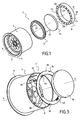
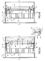
- the flow conditioner 2, 2 ' essentially comprises a tubular main body 4 of axis XX 'forming a support. At its end downstream, the main body 4 has a collar 6 for fixing it on a gas transport pipeline (not shown). The body main 4 is disposed inside the pipe so that its axis XX 'is confused with that of the pipe.
- the conditioner 2, 2 ' also comprises at least one flow straightener 8 disposed inside the main body 4 substantially perpendicular to the axis XX 'thereof, and a plate porous 10 disposed inside the main body 4 upstream of the flow straightener 8 parallel thereto.
- the flow straightener can be a perforated plate 8 fixed inside the main body 4. It can for example be formed in one piece with the main body 4. It also has openings whose distribution and dimensions are optimized to participate in the mitigation of disturbances of the flow of gas. For example, it may include a central hole 12 and a set of holes 12 'distributed over several rings concentric centered on the axis XX 'of the main body 4.
- the flow rectifier may be of type beam of tubes or finned.
- the porous plate 10 is positioned inside the body principal 4 so that a substantial part (or all) of the gas passes through the porous plate and the perforated plate 8 in the absence of clogging of the porous plate.
- the porous plate 10 makes it possible to improve efficiency of the flow conditioner by helping to eliminate the dissymmetries and to mitigate the high levels of turbulence. She has a excellent homogenizing power on the flow while destroying the big turbulent structures.
- the porous material used is an alloy of nickel-chromium.
- the average pore diameter can be advantageously of the order of 0.9 mm with a contact surface with the flow (or surface area) of the order of 1700 m2 / m3 and a thickness of the order 10 mm.
- the flow conditioner further comprises a circuit for diversion to ensure flow continuity of the gas flow in case of clogging of the porous plate.
- clogging the plate porous it is meant that the pores thereof are at least partially clogged with impurities from the gas so the loss of charge increases sharply.
- the branch circuit comprises a fixed element and an element movable arranged inside the main body, the movable element being contact with the fixed element in the absence of clogging of the plate porous and able to be moved axially in translation downstream by relative to the fixed element so as to clear a bypass passage for the gas in case of clogging of said porous plate.
- the branch circuit further comprises means for keep the moving element in contact with the fixed element in the absence of clogging of the porous plate and means of translation of the element movable relative to the fixed member so as to allow movement of this movable element in case of clogging of the porous plate.
- the movable element of the branch circuit is a support ring 14 of the porous plate 10 having an external diameter D1 less than one internal diameter D2 of the main body.
- the porous plate is for example fixed on the movable ring 14 by means of pressure screws 15.
- the fixed element of the branch circuit is a ring 16 disposed within the main body 4 upstream of the porous plate 10, parallel thereto and having an internal diameter D3 less than external diameter D1 of the movable ring 14.
- the fixing of the crown 16 on the main body 4 is made using clamping screws 18.
- the fixed ring 16 comprises at least one permanent magnet 20 for producing a magnetic attraction force for maintaining of the mobile ring 14 in the absence of clogging of the porous plate 10.
- the movable ring 14 essentially consists of at least one ferromagnetic element, chosen for example from among the elements iron, nickel and cobalt.
- the fixed ring 16 comprises a plurality permanent magnets 20 made for example of samarium-cobalt alloy and which are regularly distributed over its entire circumference.
- such magnets may have a diameter of 8 mm and a length of 20 mm with a load bearing strength of the order of 2.2 kg.
- the magnetic attraction force for holding the movable ring 14 in the absence of clogging of the porous plate 10 can be obtained by minus one electromagnet (not shown) attached to the fixed ring gear 16.
- the mobile ring 14 is also essentially constituted of minus one ferromagnetic element.
- the movable ring 14 comprises at least one guide rod 22 extending axially upstream and cooperating with a hole 24 practiced through the fixed ring 16 so as to allow translation axial of the movable ring relative to the fixed ring.
- the movable ring 14 preferably comprises two rods of guidance 22 diametrically opposed. These guide rods are examples welded to the movable ring 14.
- each of these guide rods 22 is provided with an adjustable element 26 forming a stop with an upstream face of the fixed crown 16.
- the distance between perforated plate 8 and the porous plate 10 is for example between 5 and 25 mm, and preferably of the order of 10 mm.
- the retaining force of the movable ring 14 on the fixed ring 16 can be adjusted according to the number of magnets 20 implanted on the fixed crown. This adjustment is made according to the diameter of the pipe on which is mounted the conditioner and according to the tolerated level of clogging of the porous material.
- a mode of operation intermediate conditioner 2 is possible.
- the support ring of the porous plate is fixed relative to the crown and is kept at a certain distance from it, for example through a stop interposed between the ring and the crown.
- the presence of magnets in the crown is not necessary.
- the branch circuit is therefore permanently open.
- a part substantial flow of fluid passes through the porous plate and throughput remaining flows through the branch circuit.
- the entire flow of fluid flows through the derivation in order to ensure flow continuity of fluid.
- the fixed element of the branch circuit is constituted by the porous plate 10 having a lower outer diameter D4 to the inner diameter D2 of the main body 4, and the movable element is a ring 28 arranged around the porous plate 10, between the diameter outer D4 of the porous plate and the internal diameter D2 of the body principal 4.
- the porous plate 10 is for example fixed on the plate perforated 8 via fixing rods 30 extending towards the upstream parallel to the axis XX 'of the main body 4.
- the perforated plate 8 comprises at least one guide rod 32 extending axially upstream and cooperating with a hole 34 practiced through the movable ring 28 so as to allow translation axial axis thereof relative to the porous plate 10.
- the perforated plate 8 preferably comprises two guide rods 32 diametrically opposite. These guide rods are for example welded on the perforated plate 8.
- Each guide rod 32 has at its end a element 36 of the washer or nut type for forming abutment against an upstream face of the mobile ring 28.
- each guide rod 32 is elsewhere provided with a spring 38 interposed between the perforated plate 8 and the movable ring 28 so as to keep the ring mobile around the porous plate 10 in the absence of clogging thereof.
- This abutment element 40 is for example a folded tab provided with lugs which are intended to bear against a downstream face of the porous plate 10 when the movable ring 28 moves in translation downstream.
- this distance is by example of the order of 5 to 25 mm, and preferably about 10 mm.
- the retaining force of the movable ring 28 around the plate Porous 10 can also be adjusted by taring adequately the springs 38, for example depending on the diameter of the pipe and the tolerated level of clogging of the porous material.
- conditioner 2 It is not necessary that the elements of conditioner 2 'from this embodiment has ferromagnetic characteristics. They can therefore be made of any type of material resistant to fluid pressure.
- the intermediate mode of operation described in connection with the previous embodiment can also apply at conditioner 2 '.
- the ring disposed around the porous plate is fixed relative to to this one.
- the ring is kept at a distance from the plate porous for example via the tongue tabs so that the bypass circuit is permanently open.
- the bypass circuit is permanently open.
- FIG. 5 thus illustrates the gain curve of accuracy (in percentage) of a conditioner as a function of gas flow (in meters cube per hour) passing through the conditioner.
- the gain in accuracy (or precision) represents the difference between the error obtained without conditioner and that obtained with conditioner.
- curve A corresponds to a conditioner at flow without bypass circuit and curves B and C at conditioners with a branch circuit in configuration normal use (ie without clogging porous material).
- the porous plate is about 10 mm distant from the perforated plate, while for curve C, the distance between the plates porous and perforated is set to about 20 mm.
- FIG. 6 thus represents the curve of the level of noise (in decibels A) of a conditioner as a function of gas flow (in cubic meters per hour) passing through the conditioner.
- the measure was carried out in an anechoic chamber at a distance of 1 m from the pipe.
- curves E and F correspond to conditioners equipped with a bypass circuit.
- the conditioner has been tested in normal use configuration (this is say in the absence of clogging of the porous material), while for the curve F, the porous material of the conditioner is clogged and the circuit of open derivation.
Landscapes
- Engineering & Computer Science (AREA)
- General Engineering & Computer Science (AREA)
- Mechanical Engineering (AREA)
- Pipe Accessories (AREA)
- Measuring Volume Flow (AREA)
- Resistance Heating (AREA)
- Water Treatment By Electricity Or Magnetism (AREA)
- Feeding, Discharge, Calcimining, Fusing, And Gas-Generation Devices (AREA)
- Extrusion Moulding Of Plastics Or The Like (AREA)
- Rigid Pipes And Flexible Pipes (AREA)
Applications Claiming Priority (2)
| Application Number | Priority Date | Filing Date | Title |
|---|---|---|---|
| FR0401558 | 2004-02-17 | ||
| FR0401558A FR2866410B1 (fr) | 2004-02-17 | 2004-02-17 | Conditionneur d'ecoulement pour canalisation de transport de fluide |
Publications (2)
| Publication Number | Publication Date |
|---|---|
| EP1564475A1 true EP1564475A1 (de) | 2005-08-17 |
| EP1564475B1 EP1564475B1 (de) | 2009-05-20 |
Family
ID=34685033
Family Applications (1)
| Application Number | Title | Priority Date | Filing Date |
|---|---|---|---|
| EP20050290329 Expired - Lifetime EP1564475B1 (de) | 2004-02-17 | 2005-02-15 | Strömungskonditionierer für fluidtreibende Leitung |
Country Status (8)
| Country | Link |
|---|---|
| US (1) | US7370675B2 (de) |
| EP (1) | EP1564475B1 (de) |
| CN (1) | CN100414167C (de) |
| AT (1) | ATE431917T1 (de) |
| CA (1) | CA2496715C (de) |
| DE (1) | DE602005014519D1 (de) |
| ES (1) | ES2327426T3 (de) |
| FR (1) | FR2866410B1 (de) |
Cited By (3)
| Publication number | Priority date | Publication date | Assignee | Title |
|---|---|---|---|---|
| EP2159553A3 (de) * | 2008-07-29 | 2012-01-18 | Saeta GmbH & Co. KG | Anlage und Verfahren zur Abgabe von Flüssigkeit aus einem mehrere Kammern enthaltenden Tankwagen im Wesentlichen durch Schwerkraft |
| CN102392925A (zh) * | 2011-03-30 | 2012-03-28 | 上海锅炉厂有限公司 | 一种节流装置 |
| WO2017127028A2 (en) | 2016-01-20 | 2017-07-27 | Malad, S.R.O. | The rectifier for symmetrical flow of fluid in a pipeline |
Families Citing this family (38)
| Publication number | Priority date | Publication date | Assignee | Title |
|---|---|---|---|---|
| CN1942635B (zh) * | 2004-02-06 | 2010-12-15 | Jvl工程有限公司 | 节水装置 |
| DE102007001052B4 (de) * | 2007-01-03 | 2011-01-05 | Airbus Deutschland Gmbh | Blendensystem zur Verwendung in einer Klimaanlage, insbesondere einer Flugzeugklimaanlage |
| US7845688B2 (en) | 2007-04-04 | 2010-12-07 | Savant Measurement Corporation | Multiple material piping component |
| DE102008049891B4 (de) * | 2008-10-02 | 2012-12-06 | Hydrometer Gmbh | Strömungsrichter für ein Durchflussmessgerät, insbesondere ein Ultraschallmessgerät |
| FR2940676B1 (fr) * | 2008-12-31 | 2011-04-01 | Total Raffinage Marketing | Dispositif d'amortissement de variation de pression dans une enceinte fermee |
| US20100246743A1 (en) * | 2009-03-30 | 2010-09-30 | Ge-Hitachi Nuclear Energy Americas, Llc | Steam flow vortex straightener |
| EP2260937A1 (de) * | 2009-06-12 | 2010-12-15 | DSM IP Assets B.V. | Vorrichtung zur Verarbeitung und Vorbereitung von Material, das durch eine Vorrichtung transportiert wird |
| US9097364B2 (en) * | 2012-03-27 | 2015-08-04 | Fisher Controls International Llc | Flow straightening seat ring and control valve having flow straightening seat ring |
| US9057391B2 (en) * | 2012-05-17 | 2015-06-16 | Canada Pipeline Accessories, Co. Ltd. | Reflector for fluid measurement system |
| USD713492S1 (en) | 2012-09-13 | 2014-09-16 | Canada Pipeline Accessories, Co. Ltd. | Flow conditioner with internal vanes |
| USD697581S1 (en) | 2012-09-13 | 2014-01-14 | Canada Pipeline Accessories, Co. Ltd. | Flow conditioner |
| WO2014040191A1 (en) | 2012-09-13 | 2014-03-20 | Canada Pipeline Accessories, Co. Ltd. | Flow conditioner with integral vanes |
| USD701939S1 (en) | 2013-01-11 | 2014-04-01 | Canada Pipeline Accessories, Co. Ltd | Flow conditioner |
| WO2014110673A1 (en) | 2013-01-17 | 2014-07-24 | Canada Pipeline Accessories, Co. Ltd. | Flow conditioner with integral vanes |
| US9297489B2 (en) | 2013-01-17 | 2016-03-29 | Canada Pipeline Accessories, Co. Ltd. | Extended length flow conditioner |
| USD721417S1 (en) | 2013-04-11 | 2015-01-20 | Canada Pipeline Accessories, Co., Ltd. | Flow conditioner |
| US9506484B2 (en) * | 2013-05-17 | 2016-11-29 | Cameron International Corporation | Flow conditioner and method for optimization |
| EP2999890B1 (de) | 2013-05-21 | 2018-10-10 | Canada Pipeline Accessories, Co. Ltd. | Strömungskonditionierer und verfahren zum entwurf davon |
| USD732640S1 (en) | 2013-09-02 | 2015-06-23 | Canada Pipeline Accessories, Co. Ltd. | Flow conditioner flange |
| US9927064B2 (en) | 2014-03-10 | 2018-03-27 | Toyota Motor Engineering & Manufacturing North America, Inc. | Flow-restricting plug and differential drive pinion having the same |
| DE112015001360T5 (de) | 2014-03-20 | 2016-12-01 | Canada Pipeline Accessories, Co. Ltd. | Rohranordnung mit abgestuften Strömungskonditionierern |
| IL321077A (en) | 2014-04-17 | 2025-07-01 | Compart Systems Pte Ltd | Ultra-seal gasket for joining high purity fluid pathways |
| US9752729B2 (en) | 2014-07-07 | 2017-09-05 | Canada Pipeline Accessories, Co. Ltd. | Systems and methods for generating swirl in pipelines |
| US9453520B2 (en) * | 2014-09-02 | 2016-09-27 | Canada Pipeline Accessories, Co. Ltd. | Heated flow conditioning systems and methods of using same |
| CN104573365B (zh) * | 2015-01-09 | 2017-09-05 | 华南理工大学 | 一种流动调整器性能评估方法 |
| FR3033371B1 (fr) * | 2015-03-06 | 2018-09-21 | Thermodyn | Separateur liquide/gaz et groupe motocompresseur centrifuge dote d'un tel separateur |
| DE102015105058A1 (de) * | 2015-04-01 | 2016-10-06 | Endress+Hauser Flowtec Ag | Strömungsgleichrichter |
| US9625293B2 (en) | 2015-05-14 | 2017-04-18 | Daniel Sawchuk | Flow conditioner having integral pressure tap |
| US10365143B2 (en) | 2016-09-08 | 2019-07-30 | Canada Pipeline Accessories, Co., Ltd. | Measurement ring for fluid flow in a pipeline |
| CN107014450B (zh) * | 2017-04-29 | 2023-11-14 | 成都伦慈仪表有限公司 | 降噪整流结构及其构成的超声波流量计 |
| CN108007514B (zh) * | 2017-11-29 | 2019-12-31 | 成都市三宇仪表科技发展有限公司 | 一种水表整流器 |
| US11232874B2 (en) * | 2017-12-18 | 2022-01-25 | Ge-Hitachi Nuclear Energy Americas Llc | Multiple-path flow restrictor nozzle |
| CN114829884B (zh) * | 2019-12-27 | 2026-02-06 | Abb瑞士股份有限公司 | 电磁流量计 |
| USD957568S1 (en) * | 2020-06-25 | 2022-07-12 | Wellis USA Inc. | Spa jet multiport |
| CN112555238B (zh) * | 2020-12-30 | 2022-11-01 | 深圳人本国际科技服饰有限公司 | 高压流体缓释装置 |
| CN216081636U (zh) * | 2021-09-03 | 2022-03-18 | 霍尼韦尔控制科技(中国)有限公司 | 整流器以及流量计 |
| CN114198583B (zh) * | 2021-11-05 | 2023-06-20 | 中国船舶重工集团公司第七一九研究所 | 一种交汇管热疲劳缓解系统及热疲劳缓解控制方法 |
| US20250137825A1 (en) * | 2023-10-25 | 2025-05-01 | Siargo Ltd. | Flow conditioning assembly with micromachined mass flow sensors |
Citations (3)
| Publication number | Priority date | Publication date | Assignee | Title |
|---|---|---|---|---|
| FR2319072A1 (fr) * | 1975-07-21 | 1977-02-18 | Electricite De France | Perfectionnements a l'attenuation des bruits d'ecoulement dans les fluides |
| FR2566092A1 (fr) * | 1984-06-18 | 1985-12-20 | Vibrasonic | Dispositif de commande d'ecoulement de fluide a faible niveau de bruit |
| FR2776033A1 (fr) * | 1998-03-13 | 1999-09-17 | Gaz De France | Conditionneur d'ecoulement pour canalisation de transport de gaz |
Family Cites Families (10)
| Publication number | Priority date | Publication date | Assignee | Title |
|---|---|---|---|---|
| US3050086A (en) * | 1959-06-29 | 1962-08-21 | American Radiator & Standard | Flow control having low pressure by-pass |
| US4244526A (en) * | 1978-08-16 | 1981-01-13 | Arth Michael J | Flow controlled shower head |
| US4743365A (en) * | 1985-08-26 | 1988-05-10 | Noland Wayne B | Valve filter mechanism |
| US4770212A (en) * | 1985-12-13 | 1988-09-13 | Halliburton Company | Pressure compensated flow rate controllers |
| GB2235064B (en) * | 1989-07-20 | 1993-06-02 | Univ Salford Business Services | Flow conditioner |
| US5148830A (en) * | 1991-08-30 | 1992-09-22 | Hung Liu | Flow control device |
| US5373873A (en) * | 1993-11-12 | 1994-12-20 | Victor Equipment Company | Gauge block having check valve with orifice |
| US5495872A (en) * | 1994-01-31 | 1996-03-05 | Integrity Measurement Partners | Flow conditioner for more accurate measurement of fluid flow |
| US6186179B1 (en) * | 1998-09-18 | 2001-02-13 | Panametrics, Inc. | Disturbance simulating flow plate |
| US20060081292A1 (en) * | 2004-10-15 | 2006-04-20 | Magic Plastics, Inc. | Quickly opening hinged check valve with pre-determined upstream pressure required to open |
-
2004
- 2004-02-17 FR FR0401558A patent/FR2866410B1/fr not_active Expired - Fee Related
-
2005
- 2005-02-09 CA CA2496715A patent/CA2496715C/fr not_active Expired - Fee Related
- 2005-02-09 US US11/054,697 patent/US7370675B2/en not_active Expired - Lifetime
- 2005-02-15 AT AT05290329T patent/ATE431917T1/de active
- 2005-02-15 DE DE200560014519 patent/DE602005014519D1/de not_active Expired - Lifetime
- 2005-02-15 ES ES05290329T patent/ES2327426T3/es not_active Expired - Lifetime
- 2005-02-15 EP EP20050290329 patent/EP1564475B1/de not_active Expired - Lifetime
- 2005-02-17 CN CNB2005100641478A patent/CN100414167C/zh not_active Expired - Fee Related
Patent Citations (3)
| Publication number | Priority date | Publication date | Assignee | Title |
|---|---|---|---|---|
| FR2319072A1 (fr) * | 1975-07-21 | 1977-02-18 | Electricite De France | Perfectionnements a l'attenuation des bruits d'ecoulement dans les fluides |
| FR2566092A1 (fr) * | 1984-06-18 | 1985-12-20 | Vibrasonic | Dispositif de commande d'ecoulement de fluide a faible niveau de bruit |
| FR2776033A1 (fr) * | 1998-03-13 | 1999-09-17 | Gaz De France | Conditionneur d'ecoulement pour canalisation de transport de gaz |
Cited By (4)
| Publication number | Priority date | Publication date | Assignee | Title |
|---|---|---|---|---|
| EP2159553A3 (de) * | 2008-07-29 | 2012-01-18 | Saeta GmbH & Co. KG | Anlage und Verfahren zur Abgabe von Flüssigkeit aus einem mehrere Kammern enthaltenden Tankwagen im Wesentlichen durch Schwerkraft |
| CN102392925A (zh) * | 2011-03-30 | 2012-03-28 | 上海锅炉厂有限公司 | 一种节流装置 |
| CN102392925B (zh) * | 2011-03-30 | 2013-08-21 | 上海锅炉厂有限公司 | 一种节流装置 |
| WO2017127028A2 (en) | 2016-01-20 | 2017-07-27 | Malad, S.R.O. | The rectifier for symmetrical flow of fluid in a pipeline |
Also Published As
| Publication number | Publication date |
|---|---|
| ATE431917T1 (de) | 2009-06-15 |
| ES2327426T3 (es) | 2009-10-29 |
| US20050178455A1 (en) | 2005-08-18 |
| CA2496715C (fr) | 2013-01-15 |
| US7370675B2 (en) | 2008-05-13 |
| CN1670423A (zh) | 2005-09-21 |
| DE602005014519D1 (de) | 2009-07-02 |
| FR2866410B1 (fr) | 2006-05-19 |
| CA2496715A1 (fr) | 2005-08-17 |
| CN100414167C (zh) | 2008-08-27 |
| EP1564475B1 (de) | 2009-05-20 |
| FR2866410A1 (fr) | 2005-08-19 |
Similar Documents
| Publication | Publication Date | Title |
|---|---|---|
| CA2496715C (fr) | Conditionneur d'ecoulement pour canalisation de transport de fluide | |
| EP0942220B1 (de) | Strömungskonditionierer für Gase führende Leitungen | |
| CA2776313C (fr) | Dispositif de centrage et de guidage en rotation d'un arbre de turbomachine | |
| EP0880015B1 (de) | Kompaktes Messgerät zur Messung der Gasströmung bei variablem Druck | |
| FR2507736A1 (fr) | Dispositif d'attenuation des bruits d'un fluide en ecoulement turbulent non symetrique par rapport a un axe | |
| FR3011619A1 (fr) | Injecteur de carburant pour une turbomachine | |
| EP3042071B1 (de) | Vorrichtung zur stromerzeugung für ein rohr | |
| FR2493461A1 (fr) | Dispositif de vanne a bille | |
| WO1986004887A1 (fr) | Conditionnement magnetique de l'eau dure | |
| FR2982337A1 (fr) | Clapet anti-retour | |
| CA2891076C (fr) | Support de tube d'evacuation d'air dans une turbomachine | |
| BE897189A (fr) | Valve a asservissement montee dans un train de tiges de forage, | |
| FR3073007A1 (fr) | Dispositif de maintien d'un tube de refroidissement pour carter de turbomachine | |
| EP3683429A1 (de) | Innenstruktur eines primären ausstossrohrs | |
| FR2889621A1 (fr) | Actionneur electromagnetique comportant un tube magnetique et destine a actionner une vanne hydraulique ou pneumatique | |
| FR3087855A1 (fr) | Un turbocompresseur centrifuge ayant un trajet de flux de gaz comportant une chambre de detente | |
| FR2984986A1 (fr) | Vanne anti-retour pour circuit fluidique | |
| FR3082992A1 (fr) | Dispositif electromagnetique comportant un conduit de sortie de vapeur dispose dans un boitier intermediaire | |
| CA3218773A1 (en) | Device for guiding a main air flow for an aircraft turbine engine | |
| EP1825132A1 (de) | Element für den abgaskreislauf eines verbrennungsmotors | |
| FR2945837A1 (fr) | Rampe d'alimentation d'une chambre de combustion ou de post-combustion de turbomachine | |
| CA2797332C (fr) | Robinet a joint metallique | |
| EP3394487A1 (de) | Differentialventil für flexibles unterwasserrohr | |
| EP0581636B1 (de) | Stromverbesserer für eine Entspannungsstation und Messvorrichtung | |
| FR2800829A1 (fr) | Valve de retenue de gaz |
Legal Events
| Date | Code | Title | Description |
|---|---|---|---|
| PUAI | Public reference made under article 153(3) epc to a published international application that has entered the european phase |
Free format text: ORIGINAL CODE: 0009012 |
|
| AK | Designated contracting states |
Kind code of ref document: A1 Designated state(s): AT BE BG CH CY CZ DE DK EE ES FI FR GB GR HU IE IS IT LI LT LU MC NL PL PT RO SE SI SK TR |
|
| AX | Request for extension of the european patent |
Extension state: AL BA HR LV MK YU |
|
| 17P | Request for examination filed |
Effective date: 20051214 |
|
| AKX | Designation fees paid |
Designated state(s): AT BE BG CH CY CZ DE DK EE ES FI FR GB GR HU IE IS IT LI LT LU MC NL PL PT RO SE SI SK TR |
|
| GRAP | Despatch of communication of intention to grant a patent |
Free format text: ORIGINAL CODE: EPIDOSNIGR1 |
|
| RAP1 | Party data changed (applicant data changed or rights of an application transferred) |
Owner name: GDF SUEZ |
|
| GRAS | Grant fee paid |
Free format text: ORIGINAL CODE: EPIDOSNIGR3 |
|
| GRAA | (expected) grant |
Free format text: ORIGINAL CODE: 0009210 |
|
| AK | Designated contracting states |
Kind code of ref document: B1 Designated state(s): AT BE BG CH CY CZ DE DK EE ES FI FR GB GR HU IE IS IT LI LT LU MC NL PL PT RO SE SI SK TR |
|
| REG | Reference to a national code |
Ref country code: GB Ref legal event code: FG4D Free format text: NOT ENGLISH |
|
| REG | Reference to a national code |
Ref country code: CH Ref legal event code: EP |
|
| REG | Reference to a national code |
Ref country code: IE Ref legal event code: FG4D Free format text: LANGUAGE OF EP DOCUMENT: FRENCH |
|
| REF | Corresponds to: |
Ref document number: 602005014519 Country of ref document: DE Date of ref document: 20090702 Kind code of ref document: P |
|
| REG | Reference to a national code |
Ref country code: CH Ref legal event code: NV Representative=s name: MICHELI & CIE SA |
|
| REG | Reference to a national code |
Ref country code: ES Ref legal event code: FG2A Ref document number: 2327426 Country of ref document: ES Kind code of ref document: T3 |
|
| PG25 | Lapsed in a contracting state [announced via postgrant information from national office to epo] |
Ref country code: PT Free format text: LAPSE BECAUSE OF FAILURE TO SUBMIT A TRANSLATION OF THE DESCRIPTION OR TO PAY THE FEE WITHIN THE PRESCRIBED TIME-LIMIT Effective date: 20090920 Ref country code: FI Free format text: LAPSE BECAUSE OF FAILURE TO SUBMIT A TRANSLATION OF THE DESCRIPTION OR TO PAY THE FEE WITHIN THE PRESCRIBED TIME-LIMIT Effective date: 20090520 Ref country code: LT Free format text: LAPSE BECAUSE OF FAILURE TO SUBMIT A TRANSLATION OF THE DESCRIPTION OR TO PAY THE FEE WITHIN THE PRESCRIBED TIME-LIMIT Effective date: 20090520 |
|
| PG25 | Lapsed in a contracting state [announced via postgrant information from national office to epo] |
Ref country code: SE Free format text: LAPSE BECAUSE OF FAILURE TO SUBMIT A TRANSLATION OF THE DESCRIPTION OR TO PAY THE FEE WITHIN THE PRESCRIBED TIME-LIMIT Effective date: 20090820 Ref country code: PL Free format text: LAPSE BECAUSE OF FAILURE TO SUBMIT A TRANSLATION OF THE DESCRIPTION OR TO PAY THE FEE WITHIN THE PRESCRIBED TIME-LIMIT Effective date: 20090520 Ref country code: IS Free format text: LAPSE BECAUSE OF FAILURE TO SUBMIT A TRANSLATION OF THE DESCRIPTION OR TO PAY THE FEE WITHIN THE PRESCRIBED TIME-LIMIT Effective date: 20090920 Ref country code: SI Free format text: LAPSE BECAUSE OF FAILURE TO SUBMIT A TRANSLATION OF THE DESCRIPTION OR TO PAY THE FEE WITHIN THE PRESCRIBED TIME-LIMIT Effective date: 20090520 |
|
| REG | Reference to a national code |
Ref country code: IE Ref legal event code: FD4D |
|
| PG25 | Lapsed in a contracting state [announced via postgrant information from national office to epo] |
Ref country code: DK Free format text: LAPSE BECAUSE OF FAILURE TO SUBMIT A TRANSLATION OF THE DESCRIPTION OR TO PAY THE FEE WITHIN THE PRESCRIBED TIME-LIMIT Effective date: 20090520 Ref country code: RO Free format text: LAPSE BECAUSE OF FAILURE TO SUBMIT A TRANSLATION OF THE DESCRIPTION OR TO PAY THE FEE WITHIN THE PRESCRIBED TIME-LIMIT Effective date: 20090520 Ref country code: EE Free format text: LAPSE BECAUSE OF FAILURE TO SUBMIT A TRANSLATION OF THE DESCRIPTION OR TO PAY THE FEE WITHIN THE PRESCRIBED TIME-LIMIT Effective date: 20090520 Ref country code: IE Free format text: LAPSE BECAUSE OF FAILURE TO SUBMIT A TRANSLATION OF THE DESCRIPTION OR TO PAY THE FEE WITHIN THE PRESCRIBED TIME-LIMIT Effective date: 20090520 Ref country code: CZ Free format text: LAPSE BECAUSE OF FAILURE TO SUBMIT A TRANSLATION OF THE DESCRIPTION OR TO PAY THE FEE WITHIN THE PRESCRIBED TIME-LIMIT Effective date: 20090520 |
|
| PG25 | Lapsed in a contracting state [announced via postgrant information from national office to epo] |
Ref country code: SK Free format text: LAPSE BECAUSE OF FAILURE TO SUBMIT A TRANSLATION OF THE DESCRIPTION OR TO PAY THE FEE WITHIN THE PRESCRIBED TIME-LIMIT Effective date: 20090520 |
|
| PLBE | No opposition filed within time limit |
Free format text: ORIGINAL CODE: 0009261 |
|
| STAA | Information on the status of an ep patent application or granted ep patent |
Free format text: STATUS: NO OPPOSITION FILED WITHIN TIME LIMIT |
|
| PG25 | Lapsed in a contracting state [announced via postgrant information from national office to epo] |
Ref country code: BG Free format text: LAPSE BECAUSE OF FAILURE TO SUBMIT A TRANSLATION OF THE DESCRIPTION OR TO PAY THE FEE WITHIN THE PRESCRIBED TIME-LIMIT Effective date: 20090820 |
|
| 26N | No opposition filed |
Effective date: 20100223 |
|
| PG25 | Lapsed in a contracting state [announced via postgrant information from national office to epo] |
Ref country code: MC Free format text: LAPSE BECAUSE OF NON-PAYMENT OF DUE FEES Effective date: 20100301 Ref country code: GR Free format text: LAPSE BECAUSE OF FAILURE TO SUBMIT A TRANSLATION OF THE DESCRIPTION OR TO PAY THE FEE WITHIN THE PRESCRIBED TIME-LIMIT Effective date: 20090821 |
|
| PG25 | Lapsed in a contracting state [announced via postgrant information from national office to epo] |
Ref country code: CY Free format text: LAPSE BECAUSE OF FAILURE TO SUBMIT A TRANSLATION OF THE DESCRIPTION OR TO PAY THE FEE WITHIN THE PRESCRIBED TIME-LIMIT Effective date: 20090520 |
|
| PG25 | Lapsed in a contracting state [announced via postgrant information from national office to epo] |
Ref country code: HU Free format text: LAPSE BECAUSE OF FAILURE TO SUBMIT A TRANSLATION OF THE DESCRIPTION OR TO PAY THE FEE WITHIN THE PRESCRIBED TIME-LIMIT Effective date: 20091121 |
|
| PG25 | Lapsed in a contracting state [announced via postgrant information from national office to epo] |
Ref country code: TR Free format text: LAPSE BECAUSE OF FAILURE TO SUBMIT A TRANSLATION OF THE DESCRIPTION OR TO PAY THE FEE WITHIN THE PRESCRIBED TIME-LIMIT Effective date: 20090520 |
|
| REG | Reference to a national code |
Ref country code: FR Ref legal event code: PLFP Year of fee payment: 12 |
|
| REG | Reference to a national code |
Ref country code: FR Ref legal event code: PLFP Year of fee payment: 13 |
|
| REG | Reference to a national code |
Ref country code: FR Ref legal event code: PLFP Year of fee payment: 14 |
|
| REG | Reference to a national code |
Ref country code: LU Ref legal event code: HC Owner name: GDF SUEZ; FR Free format text: FORMER OWNER: GDF SUEZ Effective date: 20190118 Ref country code: LU Ref legal event code: HC Owner name: ENGIE; FR Free format text: FORMER OWNER: GDF SUEZ Effective date: 20190118 Ref country code: LU Ref legal event code: PD Owner name: GRTGAZ; FR Free format text: FORMER OWNER: ENGIE Effective date: 20190118 |
|
| REG | Reference to a national code |
Ref country code: GB Ref legal event code: 732E Free format text: REGISTERED BETWEEN 20190131 AND 20190206 |
|
| REG | Reference to a national code |
Ref country code: CH Ref legal event code: PFA Owner name: ENGIE, FR Free format text: FORMER OWNER: GDF SUEZ, FR Ref country code: CH Ref legal event code: PUE Owner name: GRTGAZ, FR Free format text: FORMER OWNER: ENGIE, FR |
|
| REG | Reference to a national code |
Ref country code: BE Ref legal event code: HC Owner name: ENGIE; FR Free format text: DETAILS ASSIGNMENT: CHANGE OF OWNER(S), CHANGEMENT DE NOM DU PROPRIETAIRE Effective date: 20190129 Ref country code: BE Ref legal event code: PD Owner name: GRTGAZ; FR Free format text: DETAILS ASSIGNMENT: CHANGE OF OWNER(S), CESSION Effective date: 20190129 |
|
| REG | Reference to a national code |
Ref country code: NL Ref legal event code: HC Owner name: ENGIE; FR Free format text: DETAILS ASSIGNMENT: CHANGE OF OWNER(S), CHANGE OF OWNER(S) NAME; FORMER OWNER NAME: GDF SUEZ Effective date: 20190320 Ref country code: NL Ref legal event code: PD Owner name: GRTGAZ; FR Free format text: DETAILS ASSIGNMENT: CHANGE OF OWNER(S), ASSIGNMENT; FORMER OWNER NAME: ENGIE Effective date: 20190320 |
|
| REG | Reference to a national code |
Ref country code: ES Ref legal event code: PC2A Owner name: GRTGAZ Effective date: 20190823 |
|
| PGFP | Annual fee paid to national office [announced via postgrant information from national office to epo] |
Ref country code: LU Payment date: 20210126 Year of fee payment: 17 |
|
| PGFP | Annual fee paid to national office [announced via postgrant information from national office to epo] |
Ref country code: CH Payment date: 20210120 Year of fee payment: 17 Ref country code: IT Payment date: 20210120 Year of fee payment: 17 Ref country code: NL Payment date: 20210120 Year of fee payment: 17 |
|
| PGFP | Annual fee paid to national office [announced via postgrant information from national office to epo] |
Ref country code: ES Payment date: 20210301 Year of fee payment: 17 Ref country code: GB Payment date: 20210120 Year of fee payment: 17 Ref country code: DE Payment date: 20210120 Year of fee payment: 17 Ref country code: AT Payment date: 20210122 Year of fee payment: 17 Ref country code: BE Payment date: 20210125 Year of fee payment: 17 |
|
| REG | Reference to a national code |
Ref country code: DE Ref legal event code: R081 Ref document number: 602005014519 Country of ref document: DE Owner name: GRTGAZ S.A., FR Free format text: FORMER OWNER: GDF SUEZ, PARIS, FR |
|
| REG | Reference to a national code |
Ref country code: DE Ref legal event code: R119 Ref document number: 602005014519 Country of ref document: DE |
|
| REG | Reference to a national code |
Ref country code: NL Ref legal event code: MM Effective date: 20220301 |
|
| REG | Reference to a national code |
Ref country code: CH Ref legal event code: PL |
|
| REG | Reference to a national code |
Ref country code: AT Ref legal event code: MM01 Ref document number: 431917 Country of ref document: AT Kind code of ref document: T Effective date: 20220215 |
|
| REG | Reference to a national code |
Ref country code: BE Ref legal event code: MM Effective date: 20220228 |
|
| GBPC | Gb: european patent ceased through non-payment of renewal fee |
Effective date: 20220215 |
|
| PG25 | Lapsed in a contracting state [announced via postgrant information from national office to epo] |
Ref country code: LU Free format text: LAPSE BECAUSE OF NON-PAYMENT OF DUE FEES Effective date: 20220215 Ref country code: AT Free format text: LAPSE BECAUSE OF NON-PAYMENT OF DUE FEES Effective date: 20220215 |
|
| PG25 | Lapsed in a contracting state [announced via postgrant information from national office to epo] |
Ref country code: NL Free format text: LAPSE BECAUSE OF NON-PAYMENT OF DUE FEES Effective date: 20220301 |
|
| PG25 | Lapsed in a contracting state [announced via postgrant information from national office to epo] |
Ref country code: LI Free format text: LAPSE BECAUSE OF NON-PAYMENT OF DUE FEES Effective date: 20220228 Ref country code: GB Free format text: LAPSE BECAUSE OF NON-PAYMENT OF DUE FEES Effective date: 20220215 Ref country code: DE Free format text: LAPSE BECAUSE OF NON-PAYMENT OF DUE FEES Effective date: 20220901 Ref country code: CH Free format text: LAPSE BECAUSE OF NON-PAYMENT OF DUE FEES Effective date: 20220228 |
|
| PG25 | Lapsed in a contracting state [announced via postgrant information from national office to epo] |
Ref country code: BE Free format text: LAPSE BECAUSE OF NON-PAYMENT OF DUE FEES Effective date: 20220228 |
|
| REG | Reference to a national code |
Ref country code: ES Ref legal event code: FD2A Effective date: 20230329 |
|
| PG25 | Lapsed in a contracting state [announced via postgrant information from national office to epo] |
Ref country code: ES Free format text: LAPSE BECAUSE OF NON-PAYMENT OF DUE FEES Effective date: 20220216 |
|
| PG25 | Lapsed in a contracting state [announced via postgrant information from national office to epo] |
Ref country code: IT Free format text: LAPSE BECAUSE OF NON-PAYMENT OF DUE FEES Effective date: 20220215 |
|
| PGFP | Annual fee paid to national office [announced via postgrant information from national office to epo] |
Ref country code: FR Payment date: 20240223 Year of fee payment: 20 |