-
The invention is directed to turbines and, more particularly, to an improved
configuration for the root portion, known as a firtree, of a turbine bucket and
the corresponding turbine wheel broach slot into which the bucket fits. More
specifically, the present invention provides improved firtree/broach slot
configurations that reduce the number of buckets required and the stresses
acting on the buckets and wheel at the point of their attachment.
-
The third stage of a typical gas turbine can have as many as 92 buckets that
radially extend from a rotor or wheel. Each bucket has a root portion that is
configured to mate with a corresponding broach slot in the wheel. The
firtree/broach slot configurations are designed to reduce stresses that occur
transiently and at normal operating speeds.
-
Prior known firtree/broach slot configurations are disclosed in Goodwin, U.S.
Patent No. 4,260,331 issued on April 7, 1981, Pisz et al., U.S. Patent No.
4,824,328 issued on April 25, 1989, Dierksmeier et al., U.S. Patent No.
5,688,108 issued on November 18, 1997, Heppenstall, U.S. Patent No.
5,741,119 issued on April 21, 1998, Dierksmeier et al., U.S. Patent No.
5,836,742 issued on November 17, 1998, and Dierksmeier et al., U.S. Patent
No. 5,863,183 issued on January 26, 1999. Each one of these prior art
patents describes the particular details of the geometric assimilation of lines,
arcs, and angles of its disclosed firtree/broach slot configuration for the
purposes of reducing centrifugal forces, bending moments, and vibrations and
the consequential peak stresses that result at the attachment points.
-
It is desirable to reduce the number of buckets to be attached to the wheel for
a number of reasons, including fewer parts (less cost), higher natural
frequencies, less profile losses (skin friction), and reduced overtip leakage.
However, a reduction in the number of buckets also results in each individual
bucket being heavier as it covers a longer circumferential length. Simply
scaling the size of the buckets and slots on existing firtree and broach slot
configurations, while maintaining the same size wheel, to reduce the number
of buckets will not minimize the stresses acting at the attachment points.
-
It is an object of the present invention to provide an improved firtree/broach
slot configuration or form that enhances the transfer of load from the bucket
(buckets, also known as blades, include the airfoil, shank, and firtree
attachment) to the wheel (also known as disk) for a high temperature turbine
stage having 90 buckets.
-
Another object of the present invention reduces the magnitude of the pull
force on the rotor wheel by the bucket firtree and wheelpost known as the
dead rim annulus.
-
Further objects of the present invention are to reduce the magnitudes of the
concentrated stresses in the form for improved low cycle fatigue (LCF) and
high cycle fatigue (HCF) capability of both the bucket and the wheel.
-
Still further objects of the present invention are to reduce the capacity for
leaks across the stage through the firtree, and equalize the load transfer from
the bucket to the wheelpost among the tangs.
-
The present invention is designed with the intent and goal of improved fuel
efficiency over previous designs. Several measures have been taken in the
hot gas path to contribute to this goal, among them being a reduced bucket
count. Stage 3 in the turbine has 90 buckets rather than the typical 92 bucket
count. The benefits of reduced bucket count include: fewer parts (cost), higher
natural frequencies, less profile losses (skin friction), reduced overtip leakage,
etc.
-
However, a reduced count also results in each individual bucket being heavier
as it covers a longer circumferential length. This increased weight and
circumferential length have been accounted for in the new firtree form since
the prior art forms were typically designed for as many as 92 buckets.
-
The new firtree form has unique dimensions and relationships between the
bucket and wheel necessary for enhancing transfer of the bucket load into the
wheelpost, while reducing concentrated stresses and rotor pull. The new
firtree form was arrived at by iteration of form parameters and thermomechanical
loading. This form has certain key features that have improved
this load transfer successfully.
-
This form may be scaled to larger or smaller sizes provided, however, that the
rotor wheel or disk diameters are correspondingly scaled to larger or smaller
sizes or that the two sides of the bucket and wheel are offset similarly, i.e.,
wider or narrower. In addition, although a preferred range of tolerances for
the dimensions of the bucket and wheel are provided herein, those skilled in
the art will recognize that a broader range of tolerances could also be
employed in practicing the invention.
-
Although the intended use for this form is the GE 6C IGT model gas turbine,
it, or any scale of it, may be applied to other applications where blades or
buckets are attached to a rotating wheel or disk in a high temperature
environment.
-
Embodiments of the invention will now be described, by way of example with
reference to the accompanying drawings, in which:
- FIGURE 1 shows a portion of a turbine wheel with attached buckets;
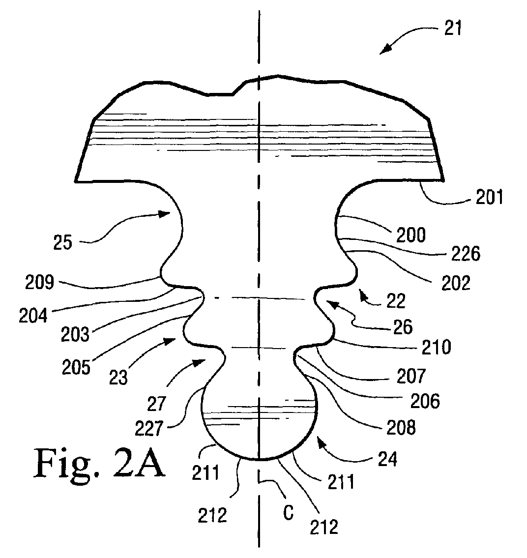
- FIGURE 2A represents a cross-sectional schematic drawing of a portion of a
bucket at the attachment and depicts the firtree profile;
- FIGURE 2B represents a cross-sectional schematic drawing of a portion of a
turbine wheel at the attachment and depicts the broach slot profile;
- FIGURE 3 shows a forward view of a bucket interlocked between
corresponding wheelposts;
- FIGURE 4 represents an interior cross-sectional schematic drawing of the
attachment portion of a bucket;
- FIGURE 5 shows a partial side view of the bucket root;
- FIGURE 6 shows gaps between an installed bucket and adjacent wheelpost
in the operating (loaded outward) condition;
- FIGURE 7 shows a perspective view of the upper edge of a wheelpost;
- FIGURE 8 shows a perspective view of the upper edge of a wheelpost with an
installed bucket;
- FIGURES 9 and 10 show dimensional aspects of a bucket;
- FIGURES 11 and 12 show dimensional aspects of the corresponding broach
slot in which the bucket of FIGURES 9 and 10 installs; and
- FIGURE 13 schematically shows zones for slight dimensional changes from
those of the preferred embodiment.
-
-
Key and fundamental elements of the invention are defined by two series of
lines, arcs, and ellipses of which the adjacent components are tangent. One
series depicts the profile or form of the firtree shape of the bucket root while
the other series depicts the profile or form of the corresponding broach slot of
the rotor wheel into which the firtree shape is fitted.
-
FIGURE 1 shows a portion of an assembled rotor wheel 10 to include buckets
11 fitted into corresponding broach slots 12. Thus, the profile of the wheel
broach slot 12 (best seen in the unfilled broach slot in FIGURE 1) is
substantially filled by the portion of the bucket 11 termed the bucket root (best
seen by the filled wheel broach slot in FIGURE 1).
-
FIGURE 2A shows in cross-sectional schematic form the profile of bucket root
21 of bucket 11. Bucket root 21 comprises three sets of curved tangs 22, 23,
24 and three sets of fillets 25, 26, 27. One tang and fillet, from each set of
tangs and fillets, is disposed on either side of centerline C. On either side of
center line C and above tangs 22 are disposed fillets 25. Tangs 22 are
disposed on either side of centerline C between fillets 25 and 26. Tangs 23
are disposed on either side of centerline C between fillets 26 and 27. Tangs
24 are joined to each other at centerline C and are disposed below fillets 27.
-
Each one of fillets 25, 26, 27 comprises an inwardly curved radial surface at
its center together with two substantially straight surfaces on either side of the
curved radial surface. In the case of fillet 25, the central curved surface is
joined to the lower straight surface by way of a transitioning arc. For each
fillet 25, curved surface 200 is connected to straight surface 201 at its upper
end that also forms an upper portion of bucket root 21, and transitioning arc
226 at its lower end. The other end of arc 226 connects to straight surface
202 that also forms a part of tang 22. For each fillet 26, curved surface 203 is
sandwiched by upper straight surface 204 that also forms a part of tang 22
and lower straight surface 205 that also forms a part of tang 23. For each
fillet 27, curved surface 206 is sandwiched by upper straight surface 207 that
also forms a part of tang 23 and lower straight surface 208 that also forms a
part of tang 24.
-
Each one of tangs 22, 23 comprises an outwardly curved radial surface
sandwiched by straight surfaces on either side. For each tang 22, curved
surface 209 is sandwiched by upper straight surface 202 that also forms a
part of fillet 25, and lower straight surface 204 that also forms a part of fillet
26. For each tang 23, curved surface 210 is sandwiched by upper straight
surface 205 that also forms a part of fillet 26 and lower straight surface 207
that also forms a part of fillet 27.
-
Each one of tangs 24 comprise an outwardly curved surface sandwiched by
curved and straight surfaces on either side. For each tang 24, outwardly
curved surface 211 connects at its upper end to elliptical surface 227 that
transitions with straight surface 208 that also forms a part of fillet 27. At its
lower end, surface 211 connects to another outwardly curved surface 212 with
the curved surfaces 212 of each tang 24 being joined at the centerline C.
-
FIGURE 2B shows in cross-sectional schematic form the profile of broach slot
12 of rotor wheel 10. Broach slot 12 comprises the physical space between
two adjacent wheelposts 13 and is thus defined by the same set of curves.
Wheelpost 13 comprises three sets of tangs 28, 29, 30 and three sets of fillets
31, 32, and 33. The fillets and tangs of broach slot 12 are complimentary to
the tangs and fillets of bucket root 21 so that bucket root 21 can be fitted
within broach slot 12.
-
Each one of tangs 29, 30 comprises an outwardly curved radial surface
sandwiched between straight surfaces. For each tang 29, curved surface 216
is sandwiched by upper straight surface 217 that also forms a part of internal
fillet 31, and lower straight surface 218 that also forms a part of fillet 32. For
each tang 30, curved surface 219 is sandwiched by the upper straight surface
220 that also forms a part of fillet 32 and lower straight surface 221 that also
forms a part of fillet 33.
-
Each one of tangs 28 comprises an outwardly curved surface connected to a
straight surface at its upper end and transitioning to a straight surface at its
lower end by way of an elliptical curve. For each tang 28, curved surface 213
connects at its upper end to straight surface 214 that forms a top surface
adjacent to another broach slot 12. At its lower end, surface 213 connects to
elliptical surface 229 that transitions into straight surface 215 that forms part
of fillet 31.
-
Each one of fillets 31, 32 comprises an inwardly curved radial surface
sandwiched by substantially straight surfaces on either side. For each fillet 31,
curved surface 222 is sandwiched by upper straight surface 215 that also
forms a part of tang 28, and lower straight surface 217 that also forms a part
of tang 29. For each fillet 32, curved surface 223 is sandwiched by upper
straight surface 218 that also forms a part of tang 29 and lower straight
surface 220 that also forms a part of tang 30.
-
Each one of fillets 33 comprises an inwardly curved surface 224 connected on
each end to another inwardly curved surface. At its upper end, surface 224
connects to curved surface 228 that transitions it into straight surface 221 that
also forms a part of tang 30. At its lower end, surface 224 connects to curved
surface 225 with these surfaces 225 of each fillet 33 being joined at the
centerline C.
-
FIGURE 3 shows a forward view of bucket root 21 interlocked within
wheelposts 13 (or installed in broach slot 12). In FIGURE 3, empty broach slot
12 is adjacent to the slot with the bucket root 21 installed and shows in
perspective upper tang 28 of wheelpost 13. The firtree and broach slot
profiles are sized to maintain adequate live rim radius to reduce the amount of
dead weight in the firtree and wheelpost. More particularly, as shown in
FIGURE 4, the neck above the bottom tang on the firtree (between fillets 27)
has been sized to carry the necessary loading at reasonable stress levels.
-
Figure 5 shows a partial side view of bucket root 21. As shown in FIGURE 6,
a small gap 60 exists between bucket root 21 and wheelpost 13 in wheel 10,
when the bucket root is inserted into the broach slot 12. This gap or
clearance is provided to facilitate the insertion of the buckets into the broach
slots and to accommodate manufacturing tolerances.
-
As shown in FIGURES 7 and 8, center region 70 of upper tangs 28 of
wheelpost 13, looking at a tangential cross-section, has been scalloped away
to reduce weight, which reduces rotor pull and stresses in wheelpost 13. The
lobes 71 on the end remain to seal against the bucket to reduce leakage
across the firtree/shank region.
-
The bucket root 21, as described above, incorporates a uniquely sized and
interleaved triple fillet and tang arrangement so as to distribute concentrated
stresses evenly over a larger region, thus lowering peak stresses and
improving LCF capability. The arrangement allows for a reduction from 92
buckets and wheelposts to 90 buckets and wheelposts for the third stage of a
turbine.
-
The radial thickness of bottom tang 24 as set by surface 14 in FIGURE 4 has
been uniquely sized such that an equalized distribution of loading exists
among the tangs. This stiffness adjustment results in even stress distributions
throughout the firtree and wheelpost thus improving the LCF capability of the
parts as well as reducing peak crush stresses on the bearing faces.
-
The fillets, between the tangs on the bucket firtree, and on the wheelpost
have been sized to reduce occurrence of peak stresses thus improving LCF
capability.
-
The fillet above the top tang on the bucket firtree incorporates a compound
fillet so as to distribute the concentrated stresses over a larger region, thus
lowering peak stresses and improving LCF capability. The top of the
wheelpost, as the form transitions away from the contact face and into the top
sealing lobe, incorporates an elliptical curve to make this transition. Likewise,
the bottom of the bucket firtree, as the form transitions away from the contact
face and into the bottom-sealing lobe, incorporates an elliptical curve to make
this transition.
-
The divergence angles D of the contact faces (angle to centerline of dovetail),
shown in FIGURES 10 and 12, are set at 18.000° so that the appropriate
balance between the crush stresses on the contact faces and the peak
stresses in the adjacent fillets is achieved. The divergence angles E also
shown in FIGURES 10 and 12, of the array of tangs on each side of the form,
have been set at 25.780° so that the appropriate balance among various limits
(p/a stress, crush stress, peak stresses, etc.) has been maintained.
-
FIGURES 9 and 10 provide exemplary and preferred dimensions of the
bucket and FIGURES 11 and 12 provide exemplary and preferred dimensions
for the broach slot into which the bucket of FIGURES 9 and 10 is inserted. In
all cases, the preferred relative dimensions with respect to the buckets and
wheelposts shown in FIGURES 9-12 are such that the line and curve
segments fall within offsets of the defined profile at ± 0.001 inches. Of
course, those skilled in the art will recognize that minor changes beyond these
tolerance ranges will not impact, to any substantial effect, the practice of the
invention, and therefore should be considered to be within the scope of the
invention. For example, a set of joined lines and curves falling within a
tolerance zone defined by profile offsets of ± .01 inches may still meet the
intent of the invention. Further, the sides of the bucket dovetail or broach,
mirrored by the centerline, may be separated differently and still fall within this
scope. For example, dimensions L1, L2, L3, L4, L9 and L10 in Figure 9 could
be increased or decreased by a constant amount to change the overall width
of the bucket dovetail.
-
As shown in FIGURE 9, the angles A that depict the angular orientation of
tang pressure faces 202, 205, and 208 relation to horizontal equal 50.000°.
The angles B of the first tang 22 and the second fillet 26 equals 52.940°. The
angles F of the second tang 23 and lowermost fillet 27, shown in FIGURE 10,
equals 58.079°. In all of the angular measurements described in this
application, the angle to be measured is defined by tangent lines along the
outer boundaries of the portions of the bucket or wheelpost to be measured or
between the center line of the bucket or wheelpost and a line defined by the
intersection points resulting from at least two sets of the aforementioned
intersecting tangent lines.
-
FIGURE 9 also shows that the termination of upper fillet 25 forms a 90.000°
angle with the center line C through the bucket as denoted by angle C'. In
FIGURE 10 angles D and E are measured from center line C to lines defined
by points at which tangent lines along the first and second fillets intersect.
Angles D and E are respectively 18.000° and 25.780°.
-
FIGURE 9 shows a number of dimensional relationships L1 through L13, L29
and L31 which define the relative position of the tangs and fillets that form the
geometric configuration of the bucket.
-
L1 measures 1.0395 inches and L2 measures .5517 inches, with L1
representing the outermost distance or width of the bucket from center line C
and L2 representing the distance from the center line C to the intersection
point of the tangent lines formed along either side of tang 22. L29 measures
.4096 inches and defines the distance from center line C to the intersection
point of tangent lines drawn along either side of tang 23. L10 measures .2723
inches and depicts the distance from the center line C to the intersection point
of a line drawn through intersection points defined above with respect to tangs
22 and 23 and a tangent line along upper straight surface 208 of tang 24.
-
L5 to L8 define the distances from the bottom surface of tang 24 to,
respectively, the uppermost straight portion of fillet 25, the intersection point of
tangent lines drawn along tang 22, the intersection point of tangent lines
drawn along tang 23, and the intersection point of a line drawn through the
intersection points defined above with respect to tangs 22 and 23 and a
tangent line along upper straight surface 208 of tang 24. These distances L5
through L8 are, respectively, 1.4530 inches, .8191 inches, .5249 inches, and
.2407 inches.
-
Distance measures L11, L31 depict the distance from the bottom of tang 24 to
the points from which the radii of curvatures for the curved portions of tang 24
are defined. L12 and L13 depict the distance from the bottom of tang 24 to,
respectively, the intersection point of tangent lines drawn along fillet 27, and
the intersection point of tangent lines drawn along fillet 26. L11, L31, L12, and L13
measure, respectively, .2074 inches, .3360 inches, .4722 inches and .7999
inches.
-
Dimensions L3 and L4, respectively, give the distance from center line C to the
intersection point of tangent lines along fillet 27 and the intersection point of
tangent lines drawn along fillet 26. L3 and L4 measure, respectively, .0739
inches and .1788 inches.
-
As noted above, tang 24 is formed in part by two radial curves having center
points offset from either side of center line C, (a third radial curve forming tang
24 has its center point on center line C the distance L31 from the bottom of
tang 24). Distance L9 shows the offsets to the right and left of center line C
(offset is only shown to the right of center line C in FIGURE 9) and measures
.0465 inches. The offset radii are shown in FIGURE 10 as R1 and measure
.1992 inches. The radius for the curve having its center point on the center
line is shown in FIGURE 10 as R13 and measures .3360 inches.
-
L27 denotes the width of the uppermost tangs 22 which measures .9261
inches, and L28 denotes the width of the intermediate tangs 23 which
measures .6916 inches.
-
In addition to radii R1 and R13, FIGURE 10 also shows radii R2 through R6
which respectively represent the radius of the lowermost fillet 27, the radius of
the intermediate tang 23, the radius of fillet 26, the radius of the uppermost
tang 22 and the radii of the uppermost fillet 25. These radii R2 through R6 are
respectively, .0695 inches, .0752 inches, .0656 inches, .0855 inches, .0718
inches (R6') and .3376 inches (R6).
-
Curve 227 joins tang 24 with fillet 37 and is an elliptical radius with semi-major
axis .0222 inches and semi-minor axis .0014 inches.
-
As noted above, FIGURES 11 and 12 show the dimensions related to the
corresponding broach slots. In FIGURES 11 and 12 the angles A, B, C' and D
through F are identical in measurement to the complementary angles A, B, C'
and D through F in FIGURES 9 and 10.
-
FIGURE 11 shows a number of dimensional relationships L14 through L26, L30
and L32 that define the relative position of the tangs and fillets that form the
geometric configuration of the broach slot.
-
L14 measures 1.0395 inches and L15 measures .5565 inches, with L14
representing the outermost distance or width of the wheelpost from center line
C and L15 representing the distance from the center line C to the intersection
point of the tangent lines formed along either side of fillet 31. L30 measures
.4144 inches and defines the distance from center line C to the intersection
point of tangent lines drawn along either side of tang fillet 32. L23 measures
.2772 inches and depicts the distance from the center line C to the
intersection point of a line drawn through the intersection points defined above
with respect to fillets 31 and 32 and a tangent line along upper straight
surface 221 of fillet 33.
-
L18 to L21 define the distances from the bottom of fillet 33 to, respectively, the
uppermost straight portion of tang 28, the intersection point of tangent lines
drawn along fillet 31, the intersection point of tangent lines drawn along fillet
32, and the intersection point of a line drawn through the intersection points
defined above with respect to fillets 31 and 32 and a tangent line along the
upper straight surface 221 of fillet 33. These distances L18 through L21 are,
respectively, 1.4530 inches, .8193 inches, .5251 inches, and .2409 inches.
-
Distance measures L24, L32 depict the distance from the bottom of fillet 33 to
the points from which the radii of curvature for the curved portions of fillet 33
are defined. L25 and L26 depict the distance from the bottom of fillet 33 to,
respectively, the intersection point of tangent lines drawn along tang 30, and
the intersection point of tangent lines drawn along tang 29. L24, L32, L25, and L26
measure, respectively, .2134 inches, .3420 inches, .4774 inches and .8002
inches.
-
Dimensions L16 and L17, respectively, give the distance from center line C to
the intersection point of tangent lines along tang 30 and the intersection point
of tangent lines drawn along tang 29. L16 and L17 measure, respectively,
.0787 inches and .1836 inches.
-
Fillet 33 is formed by two radial curves having center points offset from either
side of center line C and a third radial curve with its center point on center line
C the distance L32 from the bottom of fillet 33. The offset radii are shown in
FIGURE 12 as R7' measuring .2052 inches. Distance L22 shows the offsets to
the right and left of center line C for the offset radial curve R7'(the offset is only
shown to the right of center line C in FIGURE 11) and measures .0465 inches.
The radius for the curve having its center point on the center line is shown in
FIGURE 12 as R7 and measures .3420 inches.
-
In addition to radii R7 through R7", FIGURE 12 also shows radii R8 through R12
which respectively represent the radius of tang 30, the radius of fillet 32, the
radius of tang 29, the radius of the uppermost fillet 31 and the radius of the
uppermost tang 28. These radii R8 through R12 are respectively, .0695
inches, .0752 inches, .0656 inches, .0855 inches, and .3316 inches.
-
Curve 215 joins tang 28 with fillet 31 and is an elliptical radius with semi-major
axis .0288 inches and semi-minor axis .0045 inches.
-
FIGURE 13 schematically depicts that the bucket dovetail and wheel broach
profiles can be formed within a range of tolerances as shown by the heavy
and dotted lines. For example, with respect to the bucket, its outer
dimensions could be altered from the solid line to a shape within the dotted
lines.
-
In FIGURE 13, 'A' represents the combination of lines and curves making up
the bucket dovetail or wheel broach profile as defined exactly. 'B' represents
the zone bound by offsets of 'A' by ± 0.001 inches and contains profile
variations that meet the preferred embodiment. 'C' represents the zone
bound by offsets of the individual mirrored sides of 'A' by ± 0.01 inches and
contain profile variations that fall within the scope of the invention.
-
In particular, all of the dimensions for the bucket and wheel could be scaled
larger or smaller than those given for the preferred embodiment.
Furthermore, the two sides of the bucket (and corresponding broach slot)
could be spaced differently by increasing or decreasing dimensions L1, L2, L3,
L4, L9, L10 which would result in different bottom fillet radii 227, 211 and 212
for the bucket. Similarly, increasing or decreasing the corresponding
dimensions of the broach slot would result in different bottom fillet radii 228,
224 and 225.
-
For completeness, various aspects of the invention are set out in the following
numbered clauses:
- 1. A turbine comprising:
- a wheel (10) having ninety broach slots (12) with the wheel (10)
material between each adjacent pair of slots forming a wheelpost (13), each
one having an interleaved system of fillets (25, 26, 27, 31, 32, 33) and tangs
(22, 23, 24, 28, 29, 30); and
- ninety buckets (11) each having a corresponding interleaved system of
fillets (25, 26, 27, 31, 32, 33) and tangs (22, 23, 24, 28, 29, 30) so that said
ninety buckets (11) can be fitted one to one into said ninety broach slots (12)
on said wheel (10);
said interleaved system of fillets (25, 26, 27, 31, 32, 33) and tangs (22,
23, 24, 28, 29, 30) on said buckets (11) and wheelposts (13) reducing
stresses acting on said fitted buckets (11) and wheelposts (13). - 2. A turbine as specified in clause 1, each one of said buckets (11) and
wheelposts (13) having three interleaved tangs (22, 23, 24, 28, 29, 30) and
fillets (25, 26, 27, 31, 32, 33).
- 3. A turbine as specified in clause 2, wherein each of said buckets (11)
having a bottom tang (22, 23, 24, 28, 29, 30) formed from curved surfaces
(200, 203, 206, 209, 210, 211, 212, 213, 215, 216, 219, 222, 223, 224, 225,
227, 228) having more than one radius of curvature.
- 4. A turbine as specified in clause 3, wherein each of said buckets (11)
further includes at least one straight surface (201, 202, 204, 205, 207, 208,
214, 215, 217, 218, 220, 221).
- 5. A turbine as specified in clause 2, wherein each of said wheelposts
(13) having a bottom fillet (224, 225, 228) formed from curved surfaces (200,
203, 206, 209, 210, 211, 212, 213, 215, 216, 219, 222, 223, 224, 225, 227,
228) having more than one radius of curvature.
- 6. A turbine as specified in clause 5, wherein each of said wheelposts
(13) further includes at least one straight surface (201, 202, 204, 205, 207,
208, 214, 215, 217, 218, 220, 221).
- 7. A turbine as specified in clause 3, wherein said curved surfaces (200,
203, 206, 209, 210, 211, 212, 213, 215, 216, 219, 222, 223, 224, 225, 227,
228) have radius of curvatures of .1992 inches and .3360 inches.
- 8. A turbine as specified in clause 5, wherein said curved surfaces (200,
203, 206, 209, 210, 211, 212, 213, 215, 216, 219, 222, 223, 224, 225, 227,
228) have radius of curvatures of .2052 inches and .3420 inches.
- 9. A turbine as specified in clause 1, wherein a top edge of each one of
said wheelposts (13) being scalloped so as to reduce the weight of said wheel
(10).
- 10. A turbine comprising:
- a wheel (10) having a plurality of wheelposts (13), each one having an
interleaved system of fillets (25, 26, 27, 31, 32, 33) and tangs (22, 23, 24, 28,
29, 30); and
- a plurality of buckets (11) each having a corresponding interleaved
system of fillets (25, 26, 27, 31, 32, 33) and tangs (22, 23, 24, 28, 29, 30) so
that said plurality of buckets (11) can be fitted, one to one, into said plurality of
wheelposts (13) on said wheel (10);
wherein said interleaved system of fillets (25, 26, 27, 31, 32, 33) and
tangs (22, 23, 24, 28, 29, 30) on said buckets (11) and wheelposts (13) act to
reduce stresses acting on said fitted buckets (11) and wheelposts (13), the
fillets (25, 26, 27, 31, 32, 33) and tangs (22, 23, 24, 28, 29, 30) of said
interleaved system of fillets (25, 26, 27, 31, 32, 33) and tangs (22, 23, 24, 28,
29, 30) each being formed by a combination of curved (200, 203, 206, 209,
210, 211, 212, 213, 215, 216, 219, 222, 223, 224, 225, 227, 228) and straight
(201, 202, 204, 205, 207, 208, 214, 215, 217, 218, 220, 221) surfaces;
wherein the fillets (25, 26, 27, 31, 32, 33) formed on said plurality of
buckets (11) have angles ranging from 50° to 59°. - 11. A turbine comprising:
- a wheel having a plurality of broach slots (12), each one having an
interleaved system of fillets (25, 26, 27, 31, 32, 33) and tangs (22, 23, 24, 28,
29, 30); and
- a plurality of buckets (11) each having a corresponding interleaved
system of fillets (25, 26, 27, 31, 32, 33) and tangs (22, 23, 24, 28, 29, 30) so
that said plurality of buckets (11) can be fitted, one to one, into said plurality of
broach slots (12) on said wheel (10);
wherein said interleaved system of fillets (25, 26, 27, 31, 32, 33) and
tangs (22, 23, 24, 28, 29, 30) on said buckets (11) and wheelposts (13) act to
reduce stresses acting on said fitted buckets (11) and wheelposts (13), the
fillets (25, 26, 27, 31, 32, 33) and tangs (22, 23, 24, 28, 29, 30) of said
interleaved system of fillets (25, 26, 27, 31, 32, 33) and tangs (22, 23, 24, 28,
29, 30) each being formed by a combination of curved (200, 203, 206, 209,
210, 211, 212, 213, 215, 216, 219, 222, 223, 224, 225, 227, 228) and straight
(201, 202, 204, 205, 207, 208, 214, 215, 217, 218, 220, 221) surfaces;
wherein the fillets (25, 26, 27, 31, 32, 33) formed on said plurality of
wheelposts (13) have angles ranging from 50° to 59°. - 12. A turbine as specified in clause 11, wherein the fillets (25, 26, 27, 31,
32, 33) formed on said plurality of buckets (11) have angles ranging from 50°
to 59°.
- 13. A turbine as specified in clause 10, each one of said buckets (11) and
wheelposts (13) having three interleaved tangs (22, 23, 24, 28, 29, 30) and
fillets (25, 26, 27, 31, 32, 33).
- 14. A turbine as specified in clause 13, wherein each of said buckets (11)
having a bottom tang (22, 23, 24, 28, 29, 30) formed from curved surfaces
(200, 203, 206, 209, 210, 211, 212, 213, 215, 216, 219, 222, 223, 224, 225,
227, 228) having more than one radius of curvature.
- 15. A turbine as specified in clause 14, wherein each of said buckets (11)
further includes at least one straight surface (201, 202, 204, 205, 207, 208,
214, 215, 217, 218, 220, 221).
- 16. A turbine as specified in clause 10, wherein each of said wheelposts
(13) having a bottom fillet (25. 26, 27, 31, 32, 33) formed from curved
surfaces (200, 203, 206, 209, 210, 211, 212, 213, 215, 216, 219, 222, 223,
224, 225, 227, 228) having more than one radius of curvature.
- 17. A turbine as specified in clause 16, wherein each of said wheelposts
(13) further includes at least one straight surface (201, 202, 204, 205, 207,
208,214,215,217,218,220,221).
- 18. A turbine as specified in clause 14, wherein said curved surfaces (200,
203, 206, 209, 210, 211, 212, 213, 215, 216, 219, 222, 223, 224, 225, 227,
228) have radius of curvatures of .1992 inches and .3360 inches.
- 19. A turbine as specified in clause 16, wherein said curved surfaces (200,
203, 206, 209, 210, 211, 212, 213, 215, 216, 219, 222, 223, 224, 225, 227,
228) have radius of curvatures of .2052 inches and .3420 inches.
- 20. A turbine as specified in clause 10, wherein a top surface of each one
of said wheelposts (13) being scalloped so as to reduce the weight of said
wheel (10).
- 21. A turbine as specified in clause 11, each one of said buckets (11) and
wheelposts (13) having three interleaved tangs (22, 23, 24, 28, 29, 30) and
fillets (25, 26, 27, 31, 32, 33).
- 22. A turbine as specified in clause 21, wherein each of said buckets (11)
having a bottom tang (22, 23, 24, 28, 29, 30) formed from curved surfaces
(200, 203, 206, 209, 210, 211, 212, 213, 215, 216, 219, 222, 223, 224, 225,
227, 228) having more than one radius of curvature.
- 23. A turbine as specified in clause 22, wherein each of said buckets (11)
further includes at least one straight surface (201, 202, 204, 205, 207, 208,
214,215,217,218,220,221).
- 24. A turbine as specified in clause 21, wherein each of said wheelposts
(13) having a bottom fillet formed from curved surfaces (200, 203, 206, 209,
210, 211, 212, 213, 215, 216, 219, 222, 223, 224, 225, 227, 228) having more
than one radius of curvature.
- 25. A turbine as specified in clause 11, wherein each of said wheelposts
(13) further includes at least one straight surface (201, 202, 204, 205, 207,
208, 214, 215, 217, 218, 220, 221).
- 26. A turbine as specified in clause 22, wherein said curved surfaces (200,
203, 206, 209, 210, 211, 212, 213, 215, 216, 219, 222, 223, 224, 225, 227,
228) have radius of curvatures of .1492 inches and .3360 inches.
- 27. A turbine as specified in clause 24, wherein said curved surfaces (200,
203, 206, 209, 210, 211, 212, 213, 215, 216, 219, 222, 223, 224, 225, 227,
228) have radius of curvatures of .2052 inches and .3420 inches.
- 28. A turbine as specified in clause 11, wherein a top edge of each one of
said wheelposts (13) being scalloped so as to reduce the weight of said wheel
(10).
- 29. A bucket (11) for insertion into a wheelpost (13) of a turbine rotor 10),
said bucket (11) being formed from interleaved fillets (25, 26, 27, 31, 32, 33)
and tangs (22, 23, 24, 28, 29, 30) which complement interleaved fillets (25,
26, 27, 31, 32, 33) and tangs (22, 23, 24, 28, 29, 30) formed in the wheelpost
(13), angles of the fillets (25, 26, 27, 31, 32, 33) formed in bucket (11) ranging
from 50° to 59°.
- 30. A bucket (11) as specified in clause 29, said bucket (11) having three
interleaved tangs (22, 23, 24, 28, 29, 30) and fillets (25, 26, 27, 31, 32, 33).
- 31. A bucket (11) as specified in clause 30, said bucket (11) having a
bottom tang (22, 23, 24, 28, 29, 30) formed from curved surfaces (200, 203,
206, 209, 210, 211, 212, 213, 215, 216, 219, 222, 223, 224, 225, 227, 228)
having more than one radius of curvature.
- 32. A bucket (11) as specified in clause 31, said bucket (11) further
including at least one straight surface (201, 202, 204, 205, 207, 208, 214,
215,217,218,220,221).
- 33. A bucket (11) as specified in clause 31, said curved surfaces (200,
203, 206, 209, 210, 211, 212, 213, 215, 216, 219, 222, 223, 224, 225, 227,
228) having radii of curvatures of .1992 inches and .3360 inches.
- 34. A bucket (11) as specified in clause 30, said bucket (11) having an
upper tang (22, 23, 24, 28, 29, 30) formed from curved surfaces (200, 203,
206, 209, 210, 211, 212, 213, 215, 216, 219, 222, 223, 224, 225, 227, 228)
having more than one radius of curvature.
- 35. A bucket (11) as specified in clause 31, said bucket (11) having an
upper tang (22, 23, 24, 28, 29, 30) formed from curved surfaces (200, 203,
206, 209, 210, 211, 212, 213, 215, 216, 219, 222, 223, 224, 225, 227, 228)
having more than one radius of curvature.
- 36. A bucket (11) as specified in clause 34, said bucket (11) further
including at least one straight surface (201, 202, 204, 205, 207, 208, 214,
215, 217, 218, 220, 221).
- 37. A bucket (11) as specified in clause 30, said bucket (11) having an
intermediate tang (22, 23, 24, 28, 29, 30) formed from curved surfaces (200,
203, 206, 209, 210, 211, 212, 213, 215, 216, 219, 222, 223, 224, 225, 227,
228) having more than one radius of curvature.
- 38. A bucket (11) as specified in clause 31, said bucket (11) having an
intermediate tang (22, 23, 24, 28, 29, 30) formed from curved surfaces (200,
203, 206, 209, 210, 211, 212, 213, 215, 216, 219, 222, 223, 224, 225, 227,
228) having more than one radius of curvature.
- 39. A bucket (11) as specified in clause 35, said bucket (11) having an
intermediate tang (22, 23, 24, 28, 29, 30) formed from curved surfaces (200,
203, 206, 209, 210, 211, 212, 213, 215, 216, 219, 222, 223, 224, 225, 227,
228) having more than one radius of curvature.
- 40. A bucket (11) as specified in clause 37, said bucket (11) further
including at least one straight surface (201, 202, 204, 205, 207, 208, 214,
215, 217, 218, 220, 221).
-