EP1564373A1 - Wirbelgleichrichter in Röhrenbauweise - Google Patents
Wirbelgleichrichter in Röhrenbauweise Download PDFInfo
- Publication number
- EP1564373A1 EP1564373A1 EP05002838A EP05002838A EP1564373A1 EP 1564373 A1 EP1564373 A1 EP 1564373A1 EP 05002838 A EP05002838 A EP 05002838A EP 05002838 A EP05002838 A EP 05002838A EP 1564373 A1 EP1564373 A1 EP 1564373A1
- Authority
- EP
- European Patent Office
- Prior art keywords
- secondary air
- radially
- compressor
- rectifier according
- securing element
- Prior art date
- Legal status (The legal status is an assumption and is not a legal conclusion. Google has not performed a legal analysis and makes no representation as to the accuracy of the status listed.)
- Granted
Links
- 239000003638 chemical reducing agent Substances 0.000 title abstract 2
- 239000011324 bead Substances 0.000 claims description 12
- 238000010276 construction Methods 0.000 claims description 4
- 238000001816 cooling Methods 0.000 claims description 2
- 238000006073 displacement reaction Methods 0.000 claims 1
- 210000003437 trachea Anatomy 0.000 description 6
- 238000004519 manufacturing process Methods 0.000 description 3
- 230000008901 benefit Effects 0.000 description 2
- 238000002485 combustion reaction Methods 0.000 description 2
- 230000009471 action Effects 0.000 description 1
- 230000001419 dependent effect Effects 0.000 description 1
- 230000000694 effects Effects 0.000 description 1
- 238000005516 engineering process Methods 0.000 description 1
- 238000009434 installation Methods 0.000 description 1
- 238000012423 maintenance Methods 0.000 description 1
- 238000000034 method Methods 0.000 description 1
- 230000008569 process Effects 0.000 description 1
- 230000009467 reduction Effects 0.000 description 1
- 230000008439 repair process Effects 0.000 description 1
Images



Classifications
-
- F—MECHANICAL ENGINEERING; LIGHTING; HEATING; WEAPONS; BLASTING
- F04—POSITIVE - DISPLACEMENT MACHINES FOR LIQUIDS; PUMPS FOR LIQUIDS OR ELASTIC FLUIDS
- F04D—NON-POSITIVE-DISPLACEMENT PUMPS
- F04D29/00—Details, component parts, or accessories
- F04D29/58—Cooling; Heating; Diminishing heat transfer
- F04D29/582—Cooling; Heating; Diminishing heat transfer specially adapted for elastic fluid pumps
- F04D29/584—Cooling; Heating; Diminishing heat transfer specially adapted for elastic fluid pumps cooling or heating the machine
-
- F—MECHANICAL ENGINEERING; LIGHTING; HEATING; WEAPONS; BLASTING
- F01—MACHINES OR ENGINES IN GENERAL; ENGINE PLANTS IN GENERAL; STEAM ENGINES
- F01D—NON-POSITIVE DISPLACEMENT MACHINES OR ENGINES, e.g. STEAM TURBINES
- F01D17/00—Regulating or controlling by varying flow
- F01D17/10—Final actuators
- F01D17/105—Final actuators by passing part of the fluid
-
- F—MECHANICAL ENGINEERING; LIGHTING; HEATING; WEAPONS; BLASTING
- F01—MACHINES OR ENGINES IN GENERAL; ENGINE PLANTS IN GENERAL; STEAM ENGINES
- F01D—NON-POSITIVE DISPLACEMENT MACHINES OR ENGINES, e.g. STEAM TURBINES
- F01D5/00—Blades; Blade-carrying members; Heating, heat-insulating, cooling or antivibration means on the blades or the members
- F01D5/02—Blade-carrying members, e.g. rotors
- F01D5/08—Heating, heat-insulating or cooling means
-
- F—MECHANICAL ENGINEERING; LIGHTING; HEATING; WEAPONS; BLASTING
- F04—POSITIVE - DISPLACEMENT MACHINES FOR LIQUIDS; PUMPS FOR LIQUIDS OR ELASTIC FLUIDS
- F04D—NON-POSITIVE-DISPLACEMENT PUMPS
- F04D29/00—Details, component parts, or accessories
- F04D29/26—Rotors specially for elastic fluids
- F04D29/32—Rotors specially for elastic fluids for axial flow pumps
- F04D29/321—Rotors specially for elastic fluids for axial flow pumps for axial flow compressors
-
- F—MECHANICAL ENGINEERING; LIGHTING; HEATING; WEAPONS; BLASTING
- F05—INDEXING SCHEMES RELATING TO ENGINES OR PUMPS IN VARIOUS SUBCLASSES OF CLASSES F01-F04
- F05D—INDEXING SCHEME FOR ASPECTS RELATING TO NON-POSITIVE-DISPLACEMENT MACHINES OR ENGINES, GAS-TURBINES OR JET-PROPULSION PLANTS
- F05D2230/00—Manufacture
- F05D2230/60—Assembly methods
- F05D2230/64—Assembly methods using positioning or alignment devices for aligning or centring, e.g. pins
- F05D2230/642—Assembly methods using positioning or alignment devices for aligning or centring, e.g. pins using maintaining alignment while permitting differential dilatation
-
- F—MECHANICAL ENGINEERING; LIGHTING; HEATING; WEAPONS; BLASTING
- F05—INDEXING SCHEMES RELATING TO ENGINES OR PUMPS IN VARIOUS SUBCLASSES OF CLASSES F01-F04
- F05D—INDEXING SCHEME FOR ASPECTS RELATING TO NON-POSITIVE-DISPLACEMENT MACHINES OR ENGINES, GAS-TURBINES OR JET-PROPULSION PLANTS
- F05D2260/00—Function
- F05D2260/30—Retaining components in desired mutual position
Definitions
- the invention relates to a vortex rectifier in Tubular construction according to the features of the preamble of the main claim.
- the invention relates to a vortex rectifier for cooling air flow in a compressor of a Gas turbine with radially extending, in a morinnhunt arranged secondary air tubes, which at their radially outer end portion attached to a compressor disk are.
- Embodiments are known from the prior art, in which the secondary air tubes with appropriate brackets the discs are pressed, riveted, screwed, snapped or are forged.
- This proves to be disadvantageous that a sufficiently large working space is required, to assemble the secondary air tubes by means of suitable tools perform.
- This requires a relative large cross section of the secondary air chamber, through which the Secondary air flows into the secondary air tubes. hereby in turn, high production costs result.
- the risk that the compressor disk during assembly the secondary trachea is damaged. This results a very significant cost risk.
- the special tools lead to a not inconsiderable cost increase.
- the invention is based on the object, a vortex rectifier to create a tubular construction of the type mentioned, which with a simple structure and simpler, more reliable Usability inexpensive and safe to produce is.
- the radially inner Area of the secondary air tube fitting and radially to directed outside in a recess of a bearing flange of a Compressor is mounted.
- the secondary trachea thus becomes at its radially inner end region or foot region fitting, namely free of play, held in the recess.
- the radially outer region of Secondary air tube in a recess of a bearing leg of a Compressor disk guided radially displaceable and by means of a securing element against a radially inwardly directed Shift is secured.
- the radially outer area is thus stored so that changes in length due to temperature differences be compensated by the sliding storage can. Furthermore, in this way a double fit prevented.
- the fuse element is in the inventive Design prevents the secondary trachea at standstill of the compressor disk or the gas turbine directed radially inwards.
- the security element only at standstill of the compressor disk in effect, while it is not in with a rotation of the compressor disk Function is. It follows that the accuracy of fit and mounting accuracy of the fuse element larger tolerances can have.
- the secondary air tubes at their radially inner Area are provided with a torus, which radially from the inside abut against the respective bearing flange. hereby results in a good force application at the same time Ensuring exact positioning.
- the securing element according to the invention is in each case by means of a attached the two compressor discs connecting bolt. Thus accounts for additional fasteners for the Fuse element.
- the securing element preferably comprises a holding leg for engagement with the retaining bead of the secondary air tube. Furthermore, it is advantageous if the fuse element a comprises deformable securing leg for holding the bolt, so that the bolt can be pre-assembled or in the Repair state can not solve the fuse element.
- the contact surfaces between the secondary trachea and the compressor disk can be either spherical or flat be.
- a flat or planar configuration may have a corresponding recessed contact surface be formed on the compressor disk.
- Another advantage is the simpler installation and dismantling both in the manufacture of the gas turbine as also during maintenance work. By reducing the items as well as by reducing the work steps a significant cost reduction. Furthermore allowed the embodiment of the invention, the dimensioning of Intermediate disc chamber to optimize, in this way the Improve air flow while increasing the overall strength.
- Another advantage is that the secondary air tubes for balancing or balancing the compressor easily are interchangeable.
- Fig. 7 shows a partial sectional view of an inventive Gas turbine.
- Reference numeral 1 shows a compressor, which rotor blades 11 and stator blades 12 includes.
- the Rotor blades 11 are attached to compressor disks 3 and 4, respectively. These form an intermediate disc chamber 5, in which arranged a plurality of radially arranged secondary air tubes 2 are.
- the reference numeral 13 indicates a combustion chamber,
- Reference numeral 14 schematically shows a turbine. The arrows result in the schematic course of the secondary air duct.
- Figs. 1 and 2 show embodiments of the prior Technology. It can be seen that the end portions of the secondary air tubes riveted, as this is by the Reference 15 gives.
- the reference numeral 16 is an additional Carrier disk shown which an additional volume Component forms and in the intermediate disc chamber. 5 is mounted.
- FIG. 2 shows a similar embodiment, in which the reference numeral 15 again shows a riveted connection. It can be seen in particular that a very large secondary air chamber 17 is required to introduce the riveting tool.
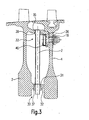
- Fig. 3 shows in the sectional view of an inventive Embodiment in the assembled state. It can be seen from this that the secondary air tube 2 at its radially inner, the axis of rotation of the gas turbine facing area with an annular bead 37 is provided which with a detail not designated, radially outwardly facing contact surface is provided. This contact surface lies against a bearing flange 32, which is integral with the compressor disk 3rd is trained. The secondary air tube 2 is accordingly through a recess 31 of the bearing flange 32 feasible.
- the secondary air tube 2 provided with a holding bead 38.
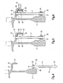
- the retaining bead 38 has a Outer diameter, which is smaller than the inner diameter the recess 31, so that the secondary air tube from the inside, as shown in Fig. 4, is pushed through.
- the retaining bead 38 is in the mounted state with a game against a bearing leg 35 of the compressor disk 3, so that no double match results.
- the inner diameter of a recess 34 of the bearing leg 35 is preferably chosen so that the end portion of the secondary air tube 2 longitudinally displaceable is, but is kept vibration-free.
- a threaded bolt is provided, which also serves for fixing a securing element 36.
- a radially outer portion 33 of the secondary air tube 2 prevented from sliding radially inward, when the compressor 1 is at a standstill.
- the radial outward force during operation of the compressor 1 is in the manner described at a radially inner Area 30 of the secondary trachea 2 was added.
- the securing element 36 comprises an extended holding leg 39 (see Fig. 5 and 6), which against the retaining bead 38 is present or to this a certain game. additionally is the securing element 36 with a securing leg 40 provided (see FIGS. 5 and 6), which after assembly deformable to hold the head of the threaded bolt 18.
- Figs. 4 to 6 show the progress of assembly.
- the secondary air tube 2 from the inside out is first performed by the bearing flange 32.
- the radially outer portion 33 is in the recess 34th introduced while the radially inner region 30 due is inserted into the recess 31, wherein the Ring bead 37 fits against the contact surface of the bearing flange 32 applies.
Landscapes
- Engineering & Computer Science (AREA)
- Mechanical Engineering (AREA)
- General Engineering & Computer Science (AREA)
- Physics & Mathematics (AREA)
- Thermal Sciences (AREA)
- Structures Of Non-Positive Displacement Pumps (AREA)
Abstract
Description
- Fig. 1
- eine schematische Teilansicht eines Ausgestaltungsbeispiels gemäß dem Stand der Technik,
- Fig. 2
- eine Ansicht, analog Fig. 1, eines weiteren Ausführungsbeispiels gemäß dem Stand der Technik,
- Fig. 3
- eine vereinfachte Schnittansicht eines erfindungsgemäßen Ausführungsbeispiels,
- Fig. 4-6
- den Montageablauf der in Fig. 3 gezeigten Ausführung, und
- Fig. 7
- eine vereinfachte Schnittansicht eines Teils einer erfindungsgemäßen Gasturbine unter Verwendung der Erfindung.
- 1
- Verdichter
- 2
- Sekundärluftröhre
- 3, 4
- Verdichterscheibe
- 5
- Zwischenscheibenkammer
- 11
- Rotorschaufel
- 12
- Statorschaufel
- 13
- Brennkammer
- 14
- Turbine
- 15
- Nietverbindung
- 16
- Trägerscheibe
- 17
- Sekundärluftkammer
- 18
- Bolzen
- 30
- radial innenliegender Bereich
- 31
- Ausnehmung
- 32
- Lagerflansch
- 33
- radial äußerer Bereich
- 34
- Ausnehmung
- 35
- Lagerschenkel
- 36
- Sicherungselement
- 37
- Ringwulst
- 38
- Haltewulst
- 39
- Halteschenkel
- 40
- Sicherungsschenkel
- 41
- Ausnehmung
- 42
- Klammer
Claims (8)
- Wirbelgleichrichter in Röhrenbauweise zur Kühlluftführung in einem Verdichter (1) einer Gasturbine, mit sich radial erstreckenden, in einer Zwischenscheibenkammer (5) angeordneten Sekundärluftröhren (2), welche an ihrem radial äußeren Endbereich (33) an einer Verdichterscheibe (3) gelagert sind, dadurch gekennzeichnet, dass der radial innenliegende Bereich (30) der Sekundärluftröhren (2) passend und radial nach außen gesichert in einer Ausnehmung (31) eines Lagerflansches (32) einer Verdichterscheibe (3) gelagert ist und dass der radial äußere Bereich (33) der Sekundärluftröhre (2) in einer Ausnehmung (34) eines Lagerschenkels (35) einer Verdichterscheibe (3) radial verschiebbar geführt und mittels eines Sicherungselements (36) gegen eine radial nach innen gerichtete Verschiebung gesichert ist.
- Wirbelgleichrichter nach Anspruch 1, dadurch gekennzeichnet, dass die Sekundärluftröhre (2) an ihrem radial innenliegenden Bereich (30) mit einer Ringwulst (37) versehen ist, welche radial von innen gegen den Lagerflansch (32) anliegt.
- Wirbelgleichrichter nach Anspruch 1 oder 2, dadurch gekennzeichnet, dass die Sekundärluftröhre (2) an ihrem radial außenliegenden Bereich (33) mit einer ringförmigen Haltewulst (38) versehen ist, gegen welche das Sicherungselement (36) in Anlage bringbar ist.
- Wirbelgleichrichter nach einem der Ansprüche 1 bis 3, dadurch gekennzeichnet, dass das Sicherungselement (36) jeweils mittels eines die beiden Verdichterscheiben (3, 4) verbindenden Bolzens (18) befestigt ist.
- Wirbelgleichrichter nach Anspruch 4, dadurch gekennzeichnet, dass das Sicherungselement (36) einen Halteschenkel (39) zur Anlage an dem Haltewulst (38) umfasst.
- Wirbelgleichrichter nach Anspruch 4 oder 5, dadurch gekennzeichnet, dass das Sicherungselement (36) einen verformbaren Sicherungsschenkel (40) zur Halterung des Bolzens (18) umfasst.
- Wirbelgleichrichter nach einem der Ansprüche 1 bis 6, dadurch gekennzeichnet, dass die Kontaktflächen der Sekundärluftröhre (2) und der Verdichterscheibe (3) sphärisch ausgebildet sind.
- Wirbelgleichrichter nach einem der Ansprüche 1 bis 6, dadurch gekennzeichnet, dass die Kontaktflächen der Sekundärluftröhre (2) und der Verdichterscheibe (3) eben ausgebildet sind.
Applications Claiming Priority (2)
| Application Number | Priority Date | Filing Date | Title |
|---|---|---|---|
| DE102004006775 | 2004-02-11 | ||
| DE102004006775A DE102004006775A1 (de) | 2004-02-11 | 2004-02-11 | Wirbelgleichrichter in Röhrenbauweise |
Publications (2)
| Publication Number | Publication Date |
|---|---|
| EP1564373A1 true EP1564373A1 (de) | 2005-08-17 |
| EP1564373B1 EP1564373B1 (de) | 2007-03-07 |
Family
ID=34684008
Family Applications (1)
| Application Number | Title | Priority Date | Filing Date |
|---|---|---|---|
| EP05002838A Ceased EP1564373B1 (de) | 2004-02-11 | 2005-02-10 | Wirbelgleichrichter in Röhrenbauweise |
Country Status (3)
| Country | Link |
|---|---|
| US (1) | US7552590B2 (de) |
| EP (1) | EP1564373B1 (de) |
| DE (2) | DE102004006775A1 (de) |
Cited By (3)
| Publication number | Priority date | Publication date | Assignee | Title |
|---|---|---|---|---|
| US8250870B2 (en) | 2008-05-19 | 2012-08-28 | Rolls-Royce Deutschland Ltd Co KG | Combined vortex reducer |
| EP2787169A1 (de) * | 2013-04-04 | 2014-10-08 | MTU Aero Engines GmbH | Rotor für eine Strömungsmaschine |
| DE102005034180B4 (de) * | 2005-07-21 | 2016-10-27 | Rolls-Royce Deutschland Ltd & Co Kg | Wirbelgleichrichter in Röhrenbauweise |
Families Citing this family (26)
| Publication number | Priority date | Publication date | Assignee | Title |
|---|---|---|---|---|
| US7448221B2 (en) * | 2004-12-17 | 2008-11-11 | United Technologies Corporation | Turbine engine rotor stack |
| US8465252B2 (en) * | 2009-04-17 | 2013-06-18 | United Technologies Corporation | Turbine engine rotating cavity anti-vortex cascade |
| US9239006B2 (en) | 2010-12-30 | 2016-01-19 | Rolls-Royce North American Technologies, Inc. | Gas turbine engine and system for modulating secondary air flow |
| US8926290B2 (en) | 2012-01-04 | 2015-01-06 | General Electric Company | Impeller tube assembly |
| US8915057B2 (en) * | 2012-02-10 | 2014-12-23 | General Electric Company | Gas turbine engine sump pressurization system |
| US9121413B2 (en) * | 2012-03-22 | 2015-09-01 | General Electric Company | Variable length compressor rotor pumping vanes |
| CN102661201B (zh) * | 2012-04-28 | 2014-02-12 | 中国航空动力机械研究所 | 发动机的引气结构 |
| US9140136B2 (en) | 2012-05-31 | 2015-09-22 | United Technologies Corporation | Stress-relieved wire seal assembly for gas turbine engines |
| US9091173B2 (en) * | 2012-05-31 | 2015-07-28 | United Technologies Corporation | Turbine coolant supply system |
| US20140090397A1 (en) * | 2012-09-28 | 2014-04-03 | United Technologies Corporation | Bleed tube attachment |
| CN103867235B (zh) * | 2012-12-18 | 2015-12-23 | 中航商用航空发动机有限责任公司 | 一种管式减涡器引气系统 |
| FR3016936B1 (fr) * | 2014-01-24 | 2019-05-17 | Safran Aircraft Engines | Disque de rotor a dispositif de prelevement d'air centripete, compresseur comportant ledit disque et turbomachine avec un tel compresseur |
| US10030517B2 (en) | 2015-01-20 | 2018-07-24 | United Technologies Corporation | Rotor disk boss |
| DE102015216110A1 (de) | 2015-08-24 | 2017-03-02 | Rolls-Royce Deutschland Ltd & Co Kg | Verdichter und Verfahren zur Montage eines Verdichters |
| FR3073581B1 (fr) * | 2017-11-14 | 2019-11-22 | Safran Aircraft Engines | Dispositif de maintien d'un organe de prelevement d'air radial centripete |
| CN112503029A (zh) * | 2019-09-16 | 2021-03-16 | 中国航发商用航空发动机有限责任公司 | 航空发动机压气机及减涡器组件 |
| US11339673B2 (en) * | 2020-01-17 | 2022-05-24 | Raytheon Technologies Corporation | Rotor assembly with internal vanes |
| CN111379736B (zh) * | 2020-04-03 | 2021-09-03 | 中国航发沈阳发动机研究所 | 一种压气机引气结构 |
| CN112065775A (zh) * | 2020-09-15 | 2020-12-11 | 中国航发沈阳发动机研究所 | 一种引气导流结构及其压气机引气结构 |
| US11414995B2 (en) * | 2020-09-17 | 2022-08-16 | Raytheon Technologies Corporation | Anti-vortex tube retaining ring and bore basket |
| CN113090593A (zh) * | 2021-05-14 | 2021-07-09 | 中国航发湖南动力机械研究所 | 适用于涡轴发动机的反旋叶片式减涡引气结构 |
| CN113898610B (zh) * | 2021-10-10 | 2024-08-02 | 中国航发沈阳发动机研究所 | 一种压气机转子轮盘盘心引气结构 |
| FR3132930B1 (fr) * | 2022-02-22 | 2024-01-12 | Safran Aircraft Engines | Turbomachine pour aéronef |
| CN114838006B (zh) * | 2022-04-29 | 2023-04-07 | 北京航空航天大学 | 一种压气机用挡板式减涡引气系统 |
| CN114838008B (zh) * | 2022-05-20 | 2023-01-20 | 北京航空航天大学 | 一种压气机径向内流盘腔可变角度反旋喷嘴减涡系统 |
| CN118517335B (zh) * | 2024-06-13 | 2025-09-12 | 北京航空航天大学 | 一种燃气轮机二次空气系统减涡结构 |
Citations (4)
| Publication number | Priority date | Publication date | Assignee | Title |
|---|---|---|---|---|
| US3398881A (en) * | 1967-01-10 | 1968-08-27 | United Aircraft Corp | Compressor bleed device |
| US4844694A (en) * | 1986-12-03 | 1989-07-04 | Societe Nationale D'etude Et De Construction De Moteurs D'aviation (Snecma) | Fastening spindle and method of assembly for attaching rotor elements of a gas-turbine engine |
| US5267832A (en) * | 1992-03-30 | 1993-12-07 | United Technologies Corporation | Flarable retainer |
| US20030101730A1 (en) * | 2001-12-05 | 2003-06-05 | Stefan Hein | Vortex reducer in the high-pressure compressor of a gas turbine |
Family Cites Families (2)
| Publication number | Priority date | Publication date | Assignee | Title |
|---|---|---|---|---|
| US5853285A (en) * | 1997-06-11 | 1998-12-29 | General Electric Co. | Cooling air tube vibration damper |
| DE10310815A1 (de) * | 2003-03-12 | 2004-09-23 | Rolls-Royce Deutschland Ltd & Co Kg | Wirbelgleichrichter in Röhrenbauweise mit Haltering |
-
2004
- 2004-02-11 DE DE102004006775A patent/DE102004006775A1/de not_active Withdrawn
-
2005
- 2005-02-10 EP EP05002838A patent/EP1564373B1/de not_active Ceased
- 2005-02-10 DE DE502005000429T patent/DE502005000429D1/de not_active Expired - Lifetime
- 2005-02-10 US US11/053,944 patent/US7552590B2/en not_active Expired - Fee Related
Patent Citations (4)
| Publication number | Priority date | Publication date | Assignee | Title |
|---|---|---|---|---|
| US3398881A (en) * | 1967-01-10 | 1968-08-27 | United Aircraft Corp | Compressor bleed device |
| US4844694A (en) * | 1986-12-03 | 1989-07-04 | Societe Nationale D'etude Et De Construction De Moteurs D'aviation (Snecma) | Fastening spindle and method of assembly for attaching rotor elements of a gas-turbine engine |
| US5267832A (en) * | 1992-03-30 | 1993-12-07 | United Technologies Corporation | Flarable retainer |
| US20030101730A1 (en) * | 2001-12-05 | 2003-06-05 | Stefan Hein | Vortex reducer in the high-pressure compressor of a gas turbine |
Cited By (3)
| Publication number | Priority date | Publication date | Assignee | Title |
|---|---|---|---|---|
| DE102005034180B4 (de) * | 2005-07-21 | 2016-10-27 | Rolls-Royce Deutschland Ltd & Co Kg | Wirbelgleichrichter in Röhrenbauweise |
| US8250870B2 (en) | 2008-05-19 | 2012-08-28 | Rolls-Royce Deutschland Ltd Co KG | Combined vortex reducer |
| EP2787169A1 (de) * | 2013-04-04 | 2014-10-08 | MTU Aero Engines GmbH | Rotor für eine Strömungsmaschine |
Also Published As
| Publication number | Publication date |
|---|---|
| DE102004006775A1 (de) | 2006-10-19 |
| US7552590B2 (en) | 2009-06-30 |
| US20050172640A1 (en) | 2005-08-11 |
| EP1564373B1 (de) | 2007-03-07 |
| DE502005000429D1 (de) | 2007-04-19 |
Similar Documents
| Publication | Publication Date | Title |
|---|---|---|
| EP1564373B1 (de) | Wirbelgleichrichter in Röhrenbauweise | |
| EP1457640B1 (de) | Wirbelgleichrichter in Röhrenbauweise mit Haltering für Gasturbinen | |
| EP2503246B1 (de) | Segmentierter Brennkammerkopf | |
| EP2806107B1 (de) | Geteilter Innenring | |
| EP2245272B1 (de) | Mehrteiliger beschaufelter rotor für eine strömungsmaschine | |
| EP3409897B1 (de) | Dichtungsanordnung für eine strömungsmaschine, verfahren zur herstellung einer dichtungsanordnung sowie strömungsmaschine | |
| EP2845999A2 (de) | Verfahren zum Auswuchten und zur Montage eines Turbinenrotors | |
| EP3006680A1 (de) | Fluggasturbinentriebwerk mit stossdämpfungselement für fanschaufelverlust | |
| EP1148209A2 (de) | Zwischenstufendichtungsanordnung | |
| EP2344723A1 (de) | Gasturbine mit dichtplatten an der turbinenscheibe | |
| DE102015116935A1 (de) | Sicherungsvorrichtung zur axialen Sicherung einer Laufschaufel und Rotorvorrichtung mit einer derartigen Sicherungsvorrichtung | |
| EP2084369A1 (de) | Leitvorrichtung einer strömungsmaschine sowie leitschaufel für eine derartige leitvorrichtung | |
| EP3287608B1 (de) | Innenring für einen leitschaufelkranz einer strömungsmaschine | |
| EP3017147B1 (de) | Rotor für eine turbine | |
| EP2378066A2 (de) | Rotor für eine Strömungsmaschine | |
| DE102016122639A1 (de) | Leitschaufelbaugruppe mit Ausgleichseinrichtung | |
| EP3176386B1 (de) | Innenringsystem, zugehöriger innenring, zwichengehäuse und strömungsmaschine | |
| WO2012004336A2 (de) | Verdichter | |
| EP3309359B1 (de) | Laufschaufelbaugruppe für ein triebwerk | |
| EP2816198B1 (de) | Leitschaufelanordnung, Leitschaufel und Verfahren zum Montieren einer Leitschaufel | |
| EP4506543A1 (de) | Leitschaufelanordnung einer strömungsmaschine, verfahren zur montage einer leitschaufelanordnung einer strömungsmaschine, und strömungsmaschine | |
| EP3327256B1 (de) | Leitschaufelbaugruppe mit ausgleichseinrichtung | |
| DE102005034180B4 (de) | Wirbelgleichrichter in Röhrenbauweise | |
| EP3115554A1 (de) | Laufschaufelanordnung mit elastischen stützelementen für eine thermische strömungsmaschine | |
| DE102021129534A1 (de) | Leitschaufelanordnung einer Strömungsmaschine und Verfahren zur Montage einer Leitschaufelanordnung |
Legal Events
| Date | Code | Title | Description |
|---|---|---|---|
| PUAI | Public reference made under article 153(3) epc to a published international application that has entered the european phase |
Free format text: ORIGINAL CODE: 0009012 |
|
| AK | Designated contracting states |
Kind code of ref document: A1 Designated state(s): AT BE BG CH CY CZ DE DK EE ES FI FR GB GR HU IE IS IT LI LT LU MC NL PL PT RO SE SI SK TR |
|
| AX | Request for extension of the european patent |
Extension state: AL BA HR LV MK YU |
|
| 17P | Request for examination filed |
Effective date: 20051130 |
|
| GRAP | Despatch of communication of intention to grant a patent |
Free format text: ORIGINAL CODE: EPIDOSNIGR1 |
|
| AKX | Designation fees paid |
Designated state(s): DE FR GB |
|
| GRAS | Grant fee paid |
Free format text: ORIGINAL CODE: EPIDOSNIGR3 |
|
| GRAA | (expected) grant |
Free format text: ORIGINAL CODE: 0009210 |
|
| AK | Designated contracting states |
Kind code of ref document: B1 Designated state(s): DE FR GB |
|
| REG | Reference to a national code |
Ref country code: GB Ref legal event code: FG4D Free format text: NOT ENGLISH |
|
| REF | Corresponds to: |
Ref document number: 502005000429 Country of ref document: DE Date of ref document: 20070419 Kind code of ref document: P |
|
| GBT | Gb: translation of ep patent filed (gb section 77(6)(a)/1977) |
Effective date: 20070417 |
|
| PLBE | No opposition filed within time limit |
Free format text: ORIGINAL CODE: 0009261 |
|
| STAA | Information on the status of an ep patent application or granted ep patent |
Free format text: STATUS: NO OPPOSITION FILED WITHIN TIME LIMIT |
|
| 26N | No opposition filed |
Effective date: 20071210 |
|
| REG | Reference to a national code |
Ref country code: DE Ref legal event code: R082 Ref document number: 502005000429 Country of ref document: DE Representative=s name: HOEFER & PARTNER, DE |
|
| REG | Reference to a national code |
Ref country code: DE Ref legal event code: R082 Ref document number: 502005000429 Country of ref document: DE Representative=s name: HOEFER & PARTNER, DE Effective date: 20130402 Ref country code: DE Ref legal event code: R081 Ref document number: 502005000429 Country of ref document: DE Owner name: ROLLS-ROYCE DEUTSCHLAND LTD & CO KG, DE Free format text: FORMER OWNER: ROLLS-ROYCE DEUTSCHLAND LTD & CO KG, 15827 BLANKENFELDE, DE Effective date: 20130402 Ref country code: DE Ref legal event code: R082 Ref document number: 502005000429 Country of ref document: DE Representative=s name: HOEFER & PARTNER PATENTANWAELTE MBB, DE Effective date: 20130402 |
|
| REG | Reference to a national code |
Ref country code: FR Ref legal event code: PLFP Year of fee payment: 12 |
|
| REG | Reference to a national code |
Ref country code: FR Ref legal event code: PLFP Year of fee payment: 13 |
|
| REG | Reference to a national code |
Ref country code: FR Ref legal event code: PLFP Year of fee payment: 14 |
|
| PGFP | Annual fee paid to national office [announced via postgrant information from national office to epo] |
Ref country code: GB Payment date: 20200227 Year of fee payment: 16 Ref country code: DE Payment date: 20200227 Year of fee payment: 16 |
|
| PGFP | Annual fee paid to national office [announced via postgrant information from national office to epo] |
Ref country code: FR Payment date: 20200225 Year of fee payment: 16 |
|
| REG | Reference to a national code |
Ref country code: DE Ref legal event code: R119 Ref document number: 502005000429 Country of ref document: DE |
|
| GBPC | Gb: european patent ceased through non-payment of renewal fee |
Effective date: 20210210 |
|
| PG25 | Lapsed in a contracting state [announced via postgrant information from national office to epo] |
Ref country code: DE Free format text: LAPSE BECAUSE OF NON-PAYMENT OF DUE FEES Effective date: 20210901 Ref country code: GB Free format text: LAPSE BECAUSE OF NON-PAYMENT OF DUE FEES Effective date: 20210210 Ref country code: FR Free format text: LAPSE BECAUSE OF NON-PAYMENT OF DUE FEES Effective date: 20210228 |