EP1564351A1 - Fencing section with flat rod panels fixed to fencing post - Google Patents
Fencing section with flat rod panels fixed to fencing post Download PDFInfo
- Publication number
- EP1564351A1 EP1564351A1 EP04100561A EP04100561A EP1564351A1 EP 1564351 A1 EP1564351 A1 EP 1564351A1 EP 04100561 A EP04100561 A EP 04100561A EP 04100561 A EP04100561 A EP 04100561A EP 1564351 A1 EP1564351 A1 EP 1564351A1
- Authority
- EP
- European Patent Office
- Prior art keywords
- fencing
- rod
- post
- vertically extending
- extending rods
- Prior art date
- Legal status (The legal status is an assumption and is not a legal conclusion. Google has not performed a legal analysis and makes no representation as to the accuracy of the status listed.)
- Granted
Links
- 229910052751 metal Inorganic materials 0.000 claims description 3
- 239000002184 metal Substances 0.000 claims description 3
- 238000009434 installation Methods 0.000 description 7
- 238000010276 construction Methods 0.000 description 4
- 239000012858 resilient material Substances 0.000 description 3
- 229910000831 Steel Inorganic materials 0.000 description 2
- 239000010959 steel Substances 0.000 description 2
- 239000004677 Nylon Substances 0.000 description 1
- HCHKCACWOHOZIP-UHFFFAOYSA-N Zinc Chemical compound [Zn] HCHKCACWOHOZIP-UHFFFAOYSA-N 0.000 description 1
- 229910000611 Zinc aluminium Inorganic materials 0.000 description 1
- 229910045601 alloy Inorganic materials 0.000 description 1
- 239000000956 alloy Substances 0.000 description 1
- HXFVOUUOTHJFPX-UHFFFAOYSA-N alumane;zinc Chemical compound [AlH3].[Zn] HXFVOUUOTHJFPX-UHFFFAOYSA-N 0.000 description 1
- 239000011248 coating agent Substances 0.000 description 1
- 238000000576 coating method Methods 0.000 description 1
- 238000006073 displacement reaction Methods 0.000 description 1
- 230000000694 effects Effects 0.000 description 1
- 229920001778 nylon Polymers 0.000 description 1
- 230000000149 penetrating effect Effects 0.000 description 1
- 229920000728 polyester Polymers 0.000 description 1
- 229920000642 polymer Polymers 0.000 description 1
- 238000003466 welding Methods 0.000 description 1
- 229910052725 zinc Inorganic materials 0.000 description 1
- 239000011701 zinc Substances 0.000 description 1
Images



Classifications
-
- E—FIXED CONSTRUCTIONS
- E04—BUILDING
- E04H—BUILDINGS OR LIKE STRUCTURES FOR PARTICULAR PURPOSES; SWIMMING OR SPLASH BATHS OR POOLS; MASTS; FENCING; TENTS OR CANOPIES, IN GENERAL
- E04H17/00—Fencing, e.g. fences, enclosures, corrals
- E04H17/14—Fences constructed of rigid elements, e.g. with additional wire fillings or with posts
- E04H17/16—Fences constructed of rigid elements, e.g. with additional wire fillings or with posts using prefabricated panel-like elements, e.g. wired frames
- E04H17/161—Fences constructed of rigid elements, e.g. with additional wire fillings or with posts using prefabricated panel-like elements, e.g. wired frames using wire panels
Definitions
- the present invention relates to a fencing section having at least one flat rod panel, a fencing post and fastening means such as bolts and nuts for fixing the rod panel to the fencing post.
- a fencing section having at least one flat rod panel, a fencing post.
- the rod panel or rod panels are fixed to the fencing post.
- the rod panel has vertically extending rods and horizontally extending rods.
- the vertically extending rods are welded to the horizontally extending rods.
- the vertically extending rods face the fencing post, i.e. the horizontally extending rods are more remote from the fencing post than the vertically extending rods.
- the fencing post is characterized by an open side with an openness that is open over at least the height of the vertically extending rods. This open side faces the rod panel or the rod panels.
- the open side has two flange portions, which limit the openness.
- the rod panel is fixed to the fencing post so that at least one vertically extending rod is housed in the openness.
- the rod panel will no longer pivot around the vertically extending rods and will remain planar or in the same plane as the other rod panels.
- the horizontally extending rods contact the flange portions, which further increases the stability of the construction and prevents the rod panels from pivoting.
- the openness allows horizontal adjustment of the rod panel in the fencing post, which will facilitate installation of the fencing section.
- installation will no longer be bound by tolerances of less than plus minus 5 mm. Tolerances or adjustments of the order of 5 cm, i.e. ten times higher than before, are now allowed.
- the fencing section comprises two rod panels.
- Each of these two rod panels has two edge rods extending vertically at each side thereof and limiting the rod panel.
- the edge rod of one of these panels and an adjacent edge rod of the other of these panels are both housed in the openness.
- the edge rod of the attacked rod panel will provide an anchorage and line contact with the relevant flange portion over its whole height, which provides a much higher resistance than the isolated fixtures of bolts and nuts in the prior art embodiment.
- the flange portions comprise vertically extending slots instead of circular holes for housing e.g. bolts as fastening means. These vertically extending slots allow vertical adjustment of the rod panel to the fencing post. These vertically extending slots help to facilitate the installation.
- the cover plate may also comprise vertically extending slots for housing bolts instead of circular holes. This allows vertical adjustment of the cover plate to the rod panel and the fencing post.
- the fencing post may be made from several pieces of metal plate, which are welded to each other.
- the fencing post is made out of a single piece of metal plate, which has been formed to the desired profile. This forming can be done in a continuous operation, after which the continuous profile is cut to the desired lengths (heights) of the fencing post.
- the means for fastening the rod panel to the fencing post may be any known means such as bolts and nuts, screws, rivets, ...
- FIGURE 1 illustrates the installation of a fencing section 10 according to the prior art.
- the fencing section 10 comprises two flat rod panels 12 and 14. Each rod panel 12, 14 comprises horizontally extending rods 16 and vertically extending rods 18. The vertically extending rods 18 are welded to the horizontally extending rods 16.
- the fencing section further comprises a hollow but closed fencing post 20 with a square cross-section. Circular cross-sections are also available.
- the rod panels 12 and 14 are fixed to fencing post 20 in an overlapping configuration by means of a clamp bar 22. Holes 26 are made in fencing post 20 and slots 28 are made in the clamp bar 22. Bolts 29 are used through the holes 26 and through the slots 28 to fix the rod panels 12 and 14 between the clamp bar 22 and the fencing post 20.
- a first drawback of this prior art fencing section 10 is as follows. If one tries to fix the rod panels 12 and 14 very tightly to the fencing post 20, a great force is applied to the horizontally extending rods 16 in the middle between two vertically extending rods 18. Since the vertically extending rods 18 keep the horizontally extending rods 16 at a distance from the fencing post 20 or at a distance from another rod panel, which distance is equal to the diameter of the vertically extending rods, the horizontally extending rods 16 start to bend and pivot with respect to the vertically extending rods 18. The result is damage on the rod panels 12 and 14. The rod panels 12 and 14 no longer lie in one single plane.
- a second drawback of the prior art fencing section 10 is as follows.
- attempts have been made to overcome the above-mentioned two drawbacks.
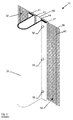
- FIGURE 2 gives a perspective view of an invention fencing section 30.
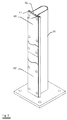
- FIGURE 3 gives a perspective view of a fencing post 36 without the rod panels.
- FIGUREs 4 give the various parts individually.
- FIGURE 4a is a frontal view of the fencing post 36.
- FIGURE 4b is a cross-section of the fencing post 36.
- FIGURE 4c is a frontal view of the covering plate 46.
- FIGURE 4d is a perspective view of fastening means.
- FIGURE 4e is a perspective view of a post cap.
- FIGURE 5 is a cross-section of an invention fencing section 30.
- a fencing section 30 according to the invention comprises two flat rod panels 32 and 34 and a fencing post 36.
- These rod panels 32, 34 are a heavy high security panel with rod diameter of 4.0 mm for both the horizontally extending rods 38 and the vertically extending rods 40.
- the horizontally extending rods and the vertically extending rods form rectangular meshes of the size 12.7 mm (height) x 76.2 mm (width), measured from the geometrical center axes of the wire rods. The height of these meshes is deliberately kept that small in order to prevent human fingers or human feet from penetrating there through or from finding support.
- the standard width of the whole rod panel 32, 34 is 2515 mm and the height of the panel can be up to 6270 mm.
- Tensile strength of the wire rods 38, 40 ranges from 540 MPa to 615 MPa.
- the horizontally extending rods 38 are welded to the vertically extending rods 40.
- the weldshear strength is about 75% of the tensile strength of the rod 38, 40.
- the weight of a rod panel 32, 34 is about 9.10 kg/m 2 .
- the wire rods 38, 40 are galvanized by means of a hot dip operation in zinc or a zinc aluminum alloy.
- the rod panels 32, 34 are coated by means of a polymer coating such as nylon or polyester. Other dimensions, other wire rod diameters, other sizes of meshes and sizes of panels are possible. As a matter of example, the wire rod diameters may vary between 3.0 mm to 7.0 mm.
- the fencing post 36 is a hollow post with an open side. Flanging portions 41 at the open side limit an openness 42 in the fencing post 36. A vertical edge rod 43 of a rod panel 34 and a vertical edge rod 44 of an adjacent rod panel 32 are housed in the openness 42. Due to this housing of the vertical edge rods 43 and 44 in the openness 42, the horizontally extending rods 38 now may contact the flange portions 41 of the fencing post over the width of the flange portions 41, which increases substantially the stability and rigidity of the construction.
- the openness 42 between the flange portions 41 allows some horizontal shifting or displacement of the rod panels 32 and 34. As a matter of example, the width of the openness 42 is 50.0 mm.
- the fencing post 36 is preferably made out of a single steel plate with, for example, a thickness of about 5.0 mm. Other suitable dimensions of thickness may vary from 3.0 to 6.0 mm.
- the final profile of the fencing post 36, with its flange portions 41, can be made by cold forming by means of a single continuous operation. There is no need for additional welding operations. After this operation the profile is cut to its required length corresponding to the height of the fencing post 36.
- the fencing post 36 can have a greatest cross-sectional dimension T ranging from e.g. 110 mm to 150 mm and more.
- a cover plate 46 is used to help to fix the rod panels 32 and 34 to the flanging portions of fencing post 36.
- more than one cover plate 46', 46" can be used.
Landscapes
- Engineering & Computer Science (AREA)
- Architecture (AREA)
- Civil Engineering (AREA)
- Structural Engineering (AREA)
- Fencing (AREA)
- Devices Affording Protection Of Roads Or Walls For Sound Insulation (AREA)
- Bridges Or Land Bridges (AREA)
Abstract
Description
- The present invention relates to a fencing section having at least one flat rod panel, a fencing post and fastening means such as bolts and nuts for fixing the rod panel to the fencing post.
- In the prior art various embodiments of fencing sections with flat rod panels and fencing posts are known. As will be explained hereafter, these embodiments suffer from three major drawbacks. First of all it is extremely difficult to fix the rod panels tightly to the fencing post and still keep the panels flat in a single plane. Secondly, the fencing sections are very vulnerable from a security point of view. It suffices to break a fencing section at or in the neighborhood of the single and isolated spots where bolts are used, to penetrate through the fencing. Thirdly, installation of the fencing section must be done in a very accurate way since high tolerances are not allowed.
- It is an object of the present invention to avoid the drawbacks of the prior art.
It is another object of the present invention to enable fixing of rod panels to fencing posts in a straight and planar way.
It is also an object of the present invention to increase the security offered by fencing sections.
It is still an object of the present invention to facilitate the installation of fencing sections. - According to the present invention there is provided a fencing section having at least one flat rod panel, a fencing post. The rod panel or rod panels are fixed to the fencing post. The rod panel has vertically extending rods and horizontally extending rods. The vertically extending rods are welded to the horizontally extending rods. The vertically extending rods face the fencing post, i.e. the horizontally extending rods are more remote from the fencing post than the vertically extending rods. The fencing post is characterized by an open side with an openness that is open over at least the height of the vertically extending rods. This open side faces the rod panel or the rod panels. The open side has two flange portions, which limit the openness. The rod panel is fixed to the fencing post so that at least one vertically extending rod is housed in the openness.
As a consequence, and as will be explained hereafter, when fixing the rod panel tightly to the fencing post, the rod panel will no longer pivot around the vertically extending rods and will remain planar or in the same plane as the other rod panels. - Preferably the horizontally extending rods contact the flange portions, which further increases the stability of the construction and prevents the rod panels from pivoting.
- Preferably the openness allows horizontal adjustment of the rod panel in the fencing post, which will facilitate installation of the fencing section. As will be explained hereinafter in more detail, installation will no longer be bound by tolerances of less than plus minus 5 mm. Tolerances or adjustments of the order of 5 cm, i.e. ten times higher than before, are now allowed.
- According to a preferable embodiment, the fencing section comprises two rod panels. Each of these two rod panels has two edge rods extending vertically at each side thereof and limiting the rod panel. The edge rod of one of these panels and an adjacent edge rod of the other of these panels are both housed in the openness. When a frontal attack is launched in the middle of one of the rod panels, the edge rod of the attacked rod panel will provide an anchorage and line contact with the relevant flange portion over its whole height, which provides a much higher resistance than the isolated fixtures of bolts and nuts in the prior art embodiment.
- The fencing section according to the invention preferably comprises a cover plate and fastening means. The cover plate overlaps with the flange portions of the fencing post. Fastening means fix the rod panel between the flange portions and the cover plate. The cover plate increases the stability of the construction. Preferably the horizontally extending rods contact the cover plate, which further increases the stability and strength of the construction.
- In a preferable embodiment, the flange portions comprise vertically extending slots instead of circular holes for housing e.g. bolts as fastening means. These vertically extending slots allow vertical adjustment of the rod panel to the fencing post. These vertically extending slots help to facilitate the installation.
The cover plate may also comprise vertically extending slots for housing bolts instead of circular holes. This allows vertical adjustment of the cover plate to the rod panel and the fencing post. - Instead of a single cover plate per fencing post, there may be provided more than one cover plate. This more than one cover plate per fencing post may overlap partially with each other, which further increases the stability of the fencing section.
- The fencing post may be made from several pieces of metal plate, which are welded to each other. Preferably, however, the fencing post is made out of a single piece of metal plate, which has been formed to the desired profile. This forming can be done in a continuous operation, after which the continuous profile is cut to the desired lengths (heights) of the fencing post.
- The means for fastening the rod panel to the fencing post may be any known means such as bolts and nuts, screws, rivets, ...
- The invention will now be described into more detail with reference to the accompanying drawings wherein
- FIGURE 1 illustrates the way in which a prior art fencing section is installed ;
- FIGURE 2 gives a perspective view of a fencing section according to the invention ;
- FIGURE 3 gives a perspective view of a fencing post according to the invention ;
- Figures 4 give the various individual components of a
fencing section according to the invention :
- o FIGURE 4a is a frontal view of a fencing post,
- o FIGURE 4b is a cross-section of the fencing post,
- o FIGURE 4c is a frontal view of a cover plate,
- o FIGURE 4d is a perspective view of fastening means,
- o FIGURE 4e is a perspective view of a cap ;
- FIGURE 5 is a cross-section of a preferable embodiment of the invention ;
- FIGURE 6 is a cross-section of an alternative embodiment of the invention ;
- FIGURE 7 is a cross-section of another alternative embodiment of the invention.
- FIGURE 1 illustrates the installation of a
fencing section 10 according to the prior art. Thefencing section 10 comprises twoflat rod panels rod panel rods 16 and vertically extendingrods 18. The vertically extendingrods 18 are welded to the horizontally extendingrods 16. The fencing section further comprises a hollow butclosed fencing post 20 with a square cross-section. Circular cross-sections are also available. Therod panels fencing post 20 in an overlapping configuration by means of aclamp bar 22.Holes 26 are made infencing post 20 andslots 28 are made in theclamp bar 22.Bolts 29 are used through theholes 26 and through theslots 28 to fix therod panels clamp bar 22 and thefencing post 20.
A first drawback of this priorart fencing section 10 is as follows. If one tries to fix therod panels fencing post 20, a great force is applied to the horizontally extendingrods 16 in the middle between two vertically extendingrods 18. Since the vertically extendingrods 18 keep the horizontally extendingrods 16 at a distance from thefencing post 20 or at a distance from another rod panel, which distance is equal to the diameter of the vertically extending rods, the horizontally extendingrods 16 start to bend and pivot with respect to the vertically extendingrods 18. The result is damage on therod panels rod panels rods 16 and thefencing post 20. The addition of such a resilient material, however, complicates the structure and is time-consuming.
A second drawback of the priorart fencing section 10 is as follows. The forces and impacts caused by a frontal attack, e.g. by a car hitting the middle of arod panel 12, must be received mainly at the isolated spots of thebolts 29. Due to the lever effect of the horizontally extendingrods 16, the fixation of therod panels fencing post 20 risks to be broken quite quickly.
In other prior art fencing sections, attempts have been made to overcome the above-mentioned two drawbacks. This has been done by the use of the above-mentioned resilient material and by the use of two bolts on the same horizontal line. However, these other prior art fencing sections suffer from following drawback. Experience by professional installation teams of these other prior art fencing sections has shown that the maximum tolerances in a horizontal direction amount to ± 8.0 mm, which is very small having regard to the size of the rod panels and to the rigidity of both the fencing posts and the rod panels. - FIGURE 2, FIGURE 3, FIGUREs 4a, 4b, 4c, 4d, 4e and FIGURE 5 all illustrate a preferable embodiment of the invention.
FIGURE 2 gives a perspective view of aninvention fencing section 30.
FIGURE 3 gives a perspective view of afencing post 36 without the rod panels.
FIGUREs 4 give the various parts individually. FIGURE 4a is a frontal view of thefencing post 36. FIGURE 4b is a cross-section of thefencing post 36. FIGURE 4c is a frontal view of the coveringplate 46.
FIGURE 4d is a perspective view of fastening means. FIGURE 4e is a perspective view of a post cap.
FIGURE 5 is a cross-section of aninvention fencing section 30. - Referring to both FIGURE 2 and FIGURE 5, a
fencing section 30 according to the invention comprises twoflat rod panels fencing post 36. - Although other rod panels are not excluded, the invention is particularly useful for
rod panels rod panels rods 38 and the vertically extendingrods 40. The horizontally extending rods and the vertically extending rods form rectangular meshes of the size 12.7 mm (height) x 76.2 mm (width), measured from the geometrical center axes of the wire rods. The height of these meshes is deliberately kept that small in order to prevent human fingers or human feet from penetrating there through or from finding support. The standard width of thewhole rod panel wire rods rods 38 are welded to the vertically extendingrods 40. The weldshear strength is about 75% of the tensile strength of therod rod panel wire rods rod panels
Other dimensions, other wire rod diameters, other sizes of meshes and sizes of panels are possible. As a matter of example, the wire rod diameters may vary between 3.0 mm to 7.0 mm. - The
fencing post 36 is a hollow post with an open side.Flanging portions 41 at the open side limit anopenness 42 in thefencing post 36. Avertical edge rod 43 of arod panel 34 and avertical edge rod 44 of anadjacent rod panel 32 are housed in theopenness 42.
Due to this housing of thevertical edge rods openness 42, the horizontally extendingrods 38 now may contact theflange portions 41 of the fencing post over the width of theflange portions 41, which increases substantially the stability and rigidity of the construction.
Theopenness 42 between theflange portions 41 allows some horizontal shifting or displacement of therod panels openness 42 is 50.0 mm. Taken into account a wire rod diameter of 5.0 mm, such openness increases the tolerances on the positioning of the fencing posts 36 to about 45.0 mm.
An external force exercised upon one of therod panels edge rods flange portions 41. A line contact is established over the whole height of therod panels rod panels fencing post 36 as the bolds no longer alone have to absorb any external forces.
Thefencing post 36 is preferably made out of a single steel plate with, for example, a thickness of about 5.0 mm. Other suitable dimensions of thickness may vary from 3.0 to 6.0 mm. The final profile of thefencing post 36, with itsflange portions 41, can be made by cold forming by means of a single continuous operation. There is no need for additional welding operations. After this operation the profile is cut to its required length corresponding to the height of thefencing post 36. Thefencing post 36 can have a greatest cross-sectional dimension T ranging from e.g. 110 mm to 150 mm and more.
Acover plate 46 is used to help to fix therod panels fencing post 36. - Referring to FIGURE 3, in an advantageous embodiment of the
fencing section 30, more than onecover plate 46', 46" can be used. - These
cover plates 46', 46" preferably overlap. This overlapping gives a supplementary rigidity and security to the fencing section. - FIGURE 4a gives a frontal view of
fencing post 36. Vertically extendingslots 50 are made in theflanging sections 41 offencing post 36. Such vertically extendingslots 50 allow some vertical adjustment of therod panels fencing post 36. Such vertically extendingslots 50 are difficult to make in prior art closed round or square fencing posts. In contrast herewith and according to an aspect of the invention, the presence of theflanging sections 41 facilitate making such vertically extendingslots 50.
FIGURE 4b gives a cross-section of afencing post 36.
FIGURE 4c is a frontal view of acover plate 46. Such acover plate 46 may be made from a steel plate of e.g. 5.0 mm thick. As with theflanging sections 41, vertically extendingslots 52 are preferably provided in the coveringplate 46. Theseslots 52 allow for some vertical adjustment of thecover plate 46 with respect to therod panels fencing post 36.
FIGURE 4d gives a perspective view of fastening means. These fastening means can bebolts 54,nuts 56 andwashers 58. Other fastening means may be screws. Thebolts 54 can be limited in length since they do not need to traverse the whole cross-section of the fencing post.
FIGURE 4e gives a perspective view of afencing post cap 60 fitting with the particular cross-section offencing post 36. - FIGURE 6 gives a cross-section of a first alternative embodiment of a fencing section according to the invention. Fencing
post 62 has an open rectangular cross-section.Flange sections 64 at the open side offencing post 62 allow fixation of therod panels - FIGURE 7 is a cross-section of a second alternative embodiment of a fencing section according to the invention. The fencing post is now made out of several parts : an open U-profile 66 and two
flange sections 68. Theflange sections 68 are connected to profile 66 by means ofwelds 70.
Claims (12)
- A fencing section comprising at least one flat rod panel, a fencing post, said rod panel being fixed to said fencing post,
said rod panel having vertically extending rods and horizontally extending rods, said vertically extending rods being welded to said horizontally extending rods, said vertically extending rods facing said fencing post,
said fencing post having an open side having an openness which is open over at least the height of the vertically extending rods, said open side facing said rod panel, said open side having two flange portions which limit said openness,
said rod panel being fixed to said fencing post so that at least one vertically extending rod is housed in said openness. - A fencing section according to claim 1 wherein said horizontally extending rods contact said flange portions.
- A fencing section according to claim 1 or claim 2 wherein said openness allows horizontal adjustment of said rod panel in said fencing post.
- A fencing section according to any one of the preceding claims, wherein said fencing section comprises two rod panels, each of said rod panels having two edge rods extending vertically at each side thereof, an edge rod of one of said panels and an adjacent edge rod of another of said panels both being housed in said openness.
- A fencing section according to any one of the preceding claims wherein said fencing section further comprises a cover plate and fastening means, said cover plate overlapping with said flange portions, said fastening means fixing said rod panel between said flange portions and said cover plate.
- A fencing section according to claim 5 wherein said horizontally extending rods contact said cover plate.
- A fencing section according to any one of the preceding claims wherein said flange portions comprise vertically extending slots for allowing vertical adjustment of said rod panel to said fencing post.
- A fencing section according to any one of claims 5 to 7 wherein said cover plate comprises vertically extending slots for allowing vertical adjustment of said cover plate to said rod panel and said fencing post.
- A fencing section according to any one of the claims 5 to 8, wherein said fencing section comprises more than one cover plate.
- A fencing section according to claim 9 wherein said more than one cover plate overlap partially with each other.
- A fencing section according to any one of the preceding claims wherein said fencing post is made out of a single piece of metal plate.
- A fencing section according to any one of the preceding claims wherein said fastening means comprise bolts and nuts.
Priority Applications (8)
| Application Number | Priority Date | Filing Date | Title |
|---|---|---|---|
| SI200430318T SI1564351T1 (en) | 2004-02-13 | 2004-02-13 | Fencing section with flat rod panels fixed to fencing post |
| EP04100561A EP1564351B1 (en) | 2004-02-13 | 2004-02-13 | Fencing section with flat rod panels fixed to fencing post |
| DE602004005567T DE602004005567T2 (en) | 2004-02-13 | 2004-02-13 | Fence construction with fence posts and attached flat grid panels |
| DK04100561T DK1564351T3 (en) | 2004-02-13 | 2004-02-13 | Fencing section with flat bar panels attached to a fence post |
| PT04100561T PT1564351E (en) | 2004-02-13 | 2004-02-13 | Fencing section with flat rod panels fixed to fencing post |
| AT04100561T ATE358220T1 (en) | 2004-02-13 | 2004-02-13 | FENCE CONSTRUCTION WITH FENCE POSTS AND FLAT GRID PANELS ATTACHED TO THEM |
| ES04100561T ES2285351T3 (en) | 2004-02-13 | 2004-02-13 | CLOSING SECTION WITH FIXED FLAT PANELS ON A POST. |
| PCT/EP2005/050067 WO2005080712A1 (en) | 2004-02-13 | 2005-01-07 | Fencing section with panel and post |
Applications Claiming Priority (1)
| Application Number | Priority Date | Filing Date | Title |
|---|---|---|---|
| EP04100561A EP1564351B1 (en) | 2004-02-13 | 2004-02-13 | Fencing section with flat rod panels fixed to fencing post |
Publications (2)
| Publication Number | Publication Date |
|---|---|
| EP1564351A1 true EP1564351A1 (en) | 2005-08-17 |
| EP1564351B1 EP1564351B1 (en) | 2007-03-28 |
Family
ID=34684740
Family Applications (1)
| Application Number | Title | Priority Date | Filing Date |
|---|---|---|---|
| EP04100561A Expired - Lifetime EP1564351B1 (en) | 2004-02-13 | 2004-02-13 | Fencing section with flat rod panels fixed to fencing post |
Country Status (8)
| Country | Link |
|---|---|
| EP (1) | EP1564351B1 (en) |
| AT (1) | ATE358220T1 (en) |
| DE (1) | DE602004005567T2 (en) |
| DK (1) | DK1564351T3 (en) |
| ES (1) | ES2285351T3 (en) |
| PT (1) | PT1564351E (en) |
| SI (1) | SI1564351T1 (en) |
| WO (1) | WO2005080712A1 (en) |
Cited By (11)
| Publication number | Priority date | Publication date | Assignee | Title |
|---|---|---|---|---|
| WO2008154661A3 (en) * | 2007-06-15 | 2009-02-05 | Richard Bruce Cochrane | Barrier |
| WO2011061507A1 (en) * | 2009-11-19 | 2011-05-26 | Zaun Limited | Fence panels and fence assemblies, and apparatus and methods of manufacturing the same |
| CN102493711A (en) * | 2011-12-07 | 2012-06-13 | 张家港固耐特围栏系统有限公司 | Fence pillar |
| CN102493710A (en) * | 2011-12-07 | 2012-06-13 | 张家港固耐特围栏系统有限公司 | Fencing post and fencing system with same |
| CN103061580A (en) * | 2012-12-31 | 2013-04-24 | 张家港固耐特围栏系统有限公司 | Fence post |
| CN103061592A (en) * | 2012-12-31 | 2013-04-24 | 张家港固耐特围栏系统有限公司 | Conveniently installed fence |
| CN103061595A (en) * | 2012-12-31 | 2013-04-24 | 张家港固耐特围栏系统有限公司 | Stand column trepanning structure on fences |
| CN104196325A (en) * | 2014-09-18 | 2014-12-10 | 张家港固耐特围栏系统有限公司 | metal fence posts |
| EP3696347A1 (en) * | 2019-01-27 | 2020-08-19 | Alois Reiterbauer | Fence post for fence panel, fence panel and fence |
| CN115613888A (en) * | 2021-02-02 | 2023-01-17 | 江苏固耐特围栏系统股份有限公司 | Net piece, stand that has net piece, rail system |
| US11891831B1 (en) * | 2018-07-17 | 2024-02-06 | Ameristar Perimeter Security Usa Inc. | Infill-covered barrier |
Families Citing this family (5)
| Publication number | Priority date | Publication date | Assignee | Title |
|---|---|---|---|---|
| CN102936973A (en) * | 2012-09-24 | 2013-02-20 | 张家港固耐特围栏系统有限公司 | Rail stand column installation seat |
| CN102852385B (en) * | 2012-09-24 | 2015-05-13 | 张家港固耐特围栏系统有限公司 | Rail column, rail unit and detection alarm rail |
| CN103061594A (en) * | 2012-12-31 | 2013-04-24 | 张家港固耐特围栏系统有限公司 | Top cover used for rail mounting |
| DE202013100055U1 (en) | 2013-01-07 | 2013-02-08 | Nikolaus Berlemann | Fence mesh, fence and retaining element or profile |
| CN103089064A (en) * | 2013-03-11 | 2013-05-08 | 张家港固耐特围栏系统有限公司 | Stand column used for installation of rail |
Citations (7)
| Publication number | Priority date | Publication date | Assignee | Title |
|---|---|---|---|---|
| DE8809307U1 (en) * | 1988-07-21 | 1988-09-01 | Häberle, Ludwig, 4760 Werl | Security fence kit |
| FR2660005A1 (en) * | 1990-03-23 | 1991-09-27 | Tmf | Fence for safety enclosure |
| FR2676487A1 (en) * | 1988-11-09 | 1992-11-20 | Gantois Ets | Improvement to fences comprising a welded wire netting connected to support posts |
| GB2276401A (en) * | 1993-03-26 | 1994-09-28 | S M Cerramiento | Securing a fencing panel to a fence post |
| EP0872612A1 (en) * | 1997-04-17 | 1998-10-21 | Orsogril S.p.A. | Locking element for fencing panels and method for the erection of the said panels |
| EP0935038A1 (en) * | 1998-02-04 | 1999-08-11 | N.V. Bekaert S.A. | Universal I-shaped fence post with matching securing devices for fixing welded wire mesh to the post |
| EP1098051A1 (en) * | 1999-11-05 | 2001-05-09 | Corinne Boutteau | Fence post and fence obtained by assembling wired panels on the posts |
-
2004
- 2004-02-13 ES ES04100561T patent/ES2285351T3/en not_active Expired - Lifetime
- 2004-02-13 EP EP04100561A patent/EP1564351B1/en not_active Expired - Lifetime
- 2004-02-13 DE DE602004005567T patent/DE602004005567T2/en not_active Expired - Lifetime
- 2004-02-13 DK DK04100561T patent/DK1564351T3/en active
- 2004-02-13 AT AT04100561T patent/ATE358220T1/en active
- 2004-02-13 SI SI200430318T patent/SI1564351T1/en unknown
- 2004-02-13 PT PT04100561T patent/PT1564351E/en unknown
-
2005
- 2005-01-07 WO PCT/EP2005/050067 patent/WO2005080712A1/en not_active Ceased
Patent Citations (7)
| Publication number | Priority date | Publication date | Assignee | Title |
|---|---|---|---|---|
| DE8809307U1 (en) * | 1988-07-21 | 1988-09-01 | Häberle, Ludwig, 4760 Werl | Security fence kit |
| FR2676487A1 (en) * | 1988-11-09 | 1992-11-20 | Gantois Ets | Improvement to fences comprising a welded wire netting connected to support posts |
| FR2660005A1 (en) * | 1990-03-23 | 1991-09-27 | Tmf | Fence for safety enclosure |
| GB2276401A (en) * | 1993-03-26 | 1994-09-28 | S M Cerramiento | Securing a fencing panel to a fence post |
| EP0872612A1 (en) * | 1997-04-17 | 1998-10-21 | Orsogril S.p.A. | Locking element for fencing panels and method for the erection of the said panels |
| EP0935038A1 (en) * | 1998-02-04 | 1999-08-11 | N.V. Bekaert S.A. | Universal I-shaped fence post with matching securing devices for fixing welded wire mesh to the post |
| EP1098051A1 (en) * | 1999-11-05 | 2001-05-09 | Corinne Boutteau | Fence post and fence obtained by assembling wired panels on the posts |
Cited By (18)
| Publication number | Priority date | Publication date | Assignee | Title |
|---|---|---|---|---|
| WO2008154661A3 (en) * | 2007-06-15 | 2009-02-05 | Richard Bruce Cochrane | Barrier |
| WO2011061507A1 (en) * | 2009-11-19 | 2011-05-26 | Zaun Limited | Fence panels and fence assemblies, and apparatus and methods of manufacturing the same |
| WO2013083044A1 (en) * | 2011-12-07 | 2013-06-13 | 张家港固耐特围栏系统有限公司 | Fence column and fence system having the fence column |
| CN102493711A (en) * | 2011-12-07 | 2012-06-13 | 张家港固耐特围栏系统有限公司 | Fence pillar |
| CN102493710A (en) * | 2011-12-07 | 2012-06-13 | 张家港固耐特围栏系统有限公司 | Fencing post and fencing system with same |
| CN102493710B (en) * | 2011-12-07 | 2015-09-16 | 张家港固耐特围栏系统有限公司 | Fence post and there is the fence system of this fence post |
| US20150041742A1 (en) * | 2011-12-07 | 2015-02-12 | Zhangjiagang Goldnet Fencing System Co., Ltd. | Fence column and fence system having the fence column |
| WO2013083045A1 (en) * | 2011-12-07 | 2013-06-13 | 张家港固耐特围栏系统有限公司 | Fence column and fence system |
| CN103061580A (en) * | 2012-12-31 | 2013-04-24 | 张家港固耐特围栏系统有限公司 | Fence post |
| CN103061595A (en) * | 2012-12-31 | 2013-04-24 | 张家港固耐特围栏系统有限公司 | Stand column trepanning structure on fences |
| CN103061592A (en) * | 2012-12-31 | 2013-04-24 | 张家港固耐特围栏系统有限公司 | Conveniently installed fence |
| CN104196325A (en) * | 2014-09-18 | 2014-12-10 | 张家港固耐特围栏系统有限公司 | metal fence posts |
| CN104196325B (en) * | 2014-09-18 | 2018-04-27 | 张家港固耐特围栏系统有限公司 | metal fence posts |
| US11891831B1 (en) * | 2018-07-17 | 2024-02-06 | Ameristar Perimeter Security Usa Inc. | Infill-covered barrier |
| EP3696347A1 (en) * | 2019-01-27 | 2020-08-19 | Alois Reiterbauer | Fence post for fence panel, fence panel and fence |
| CN115613888A (en) * | 2021-02-02 | 2023-01-17 | 江苏固耐特围栏系统股份有限公司 | Net piece, stand that has net piece, rail system |
| CN117365187A (en) * | 2021-02-02 | 2024-01-09 | 江苏固耐特围栏系统股份有限公司 | Mesh, upright post with mesh and fence system |
| CN117403962A (en) * | 2021-02-02 | 2024-01-16 | 江苏固耐特围栏系统股份有限公司 | a kind of pillar |
Also Published As
| Publication number | Publication date |
|---|---|
| DE602004005567T2 (en) | 2008-01-24 |
| EP1564351B1 (en) | 2007-03-28 |
| ES2285351T3 (en) | 2007-11-16 |
| ATE358220T1 (en) | 2007-04-15 |
| PT1564351E (en) | 2007-06-21 |
| SI1564351T1 (en) | 2007-08-31 |
| DK1564351T3 (en) | 2007-07-30 |
| WO2005080712A1 (en) | 2005-09-01 |
| DE602004005567D1 (en) | 2007-05-10 |
Similar Documents
| Publication | Publication Date | Title |
|---|---|---|
| EP1564351A1 (en) | Fencing section with flat rod panels fixed to fencing post | |
| US7396002B1 (en) | Terrain-adjustable bracket | |
| CA2698715A1 (en) | Barrier system | |
| US10604962B1 (en) | Barrier infill system | |
| US20090321701A1 (en) | Fence System | |
| WO2006114290A1 (en) | A fence panel | |
| CN102414383A (en) | Fence | |
| US6010116A (en) | High security fence assembly | |
| CN213087692U (en) | Two-piece temporary fence support | |
| WO2020245168A1 (en) | Security fencing | |
| CN215669108U (en) | Penetrating anticollision sound barrier | |
| US20110067322A1 (en) | Porthole Retrofit Apparatus for a Monopole Tower | |
| EP2628852B1 (en) | Road safety barrier structure with supporting pillar and method to install it | |
| EP1857594A1 (en) | Post for safety barrier with base plate | |
| US20060243954A1 (en) | High tension cable to metal beam guide fence transition | |
| WO2021165058A1 (en) | Fence panel | |
| JP6605916B2 (en) | Bracket, guard fence and method of assembling guard fence | |
| EP2515400B1 (en) | Device for installing conduits | |
| US20090321698A1 (en) | Panel Fence System and Method | |
| CN216055674U (en) | Novel lightning protection structure and fixing clamp for metal roof of transformer substation | |
| JP7388930B2 (en) | fence | |
| CN214467649U (en) | Support arm for mounting holding pole | |
| GB2624769A (en) | Palidsade fence rail with improved form | |
| GB2641924A (en) | Fence panel | |
| GB2588147A (en) | Security fence |
Legal Events
| Date | Code | Title | Description |
|---|---|---|---|
| PUAI | Public reference made under article 153(3) epc to a published international application that has entered the european phase |
Free format text: ORIGINAL CODE: 0009012 |
|
| AK | Designated contracting states |
Kind code of ref document: A1 Designated state(s): AT BE BG CH CY CZ DE DK EE ES FI FR GB GR HU IE IT LI LU MC NL PT RO SE SI SK TR |
|
| AX | Request for extension of the european patent |
Extension state: AL LT LV MK |
|
| 17P | Request for examination filed |
Effective date: 20051219 |
|
| AKX | Designation fees paid |
Designated state(s): AT BE BG CH CY CZ DE DK EE ES FI FR GB GR HU IE IT LI LU MC NL PT RO SE SI SK TR |
|
| AXX | Extension fees paid |
Extension state: LV Payment date: 20051219 Extension state: LT Payment date: 20051219 |
|
| GRAP | Despatch of communication of intention to grant a patent |
Free format text: ORIGINAL CODE: EPIDOSNIGR1 |
|
| GRAS | Grant fee paid |
Free format text: ORIGINAL CODE: EPIDOSNIGR3 |
|
| GRAA | (expected) grant |
Free format text: ORIGINAL CODE: 0009210 |
|
| AK | Designated contracting states |
Kind code of ref document: B1 Designated state(s): AT BE BG CH CY CZ DE DK EE ES FI FR GB GR HU IE IT LI LU MC NL PT RO SE SI SK TR |
|
| AX | Request for extension of the european patent |
Extension state: LT LV |
|
| REG | Reference to a national code |
Ref country code: GB Ref legal event code: FG4D |
|
| REG | Reference to a national code |
Ref country code: CH Ref legal event code: EP |
|
| REF | Corresponds to: |
Ref document number: 602004005567 Country of ref document: DE Date of ref document: 20070510 Kind code of ref document: P |
|
| REG | Reference to a national code |
Ref country code: IE Ref legal event code: FG4D |
|
| REG | Reference to a national code |
Ref country code: SE Ref legal event code: TRGR |
|
| REG | Reference to a national code |
Ref country code: PT Ref legal event code: SC4A Free format text: AVAILABILITY OF NATIONAL TRANSLATION Effective date: 20070611 |
|
| REG | Reference to a national code |
Ref country code: CH Ref legal event code: NV Representative=s name: SCHNEIDER FELDMANN AG PATENT- UND MARKENANWAELTE |
|
| ET | Fr: translation filed | ||
| REG | Reference to a national code |
Ref country code: DK Ref legal event code: T3 |
|
| REG | Reference to a national code |
Ref country code: HU Ref legal event code: AG4A Ref document number: E001783 Country of ref document: HU |
|
| REG | Reference to a national code |
Ref country code: ES Ref legal event code: FG2A Ref document number: 2285351 Country of ref document: ES Kind code of ref document: T3 |
|
| PG25 | Lapsed in a contracting state [announced via postgrant information from national office to epo] |
Ref country code: RO Free format text: LAPSE BECAUSE OF FAILURE TO SUBMIT A TRANSLATION OF THE DESCRIPTION OR TO PAY THE FEE WITHIN THE PRESCRIBED TIME-LIMIT Effective date: 20070328 |
|
| PLBE | No opposition filed within time limit |
Free format text: ORIGINAL CODE: 0009261 |
|
| STAA | Information on the status of an ep patent application or granted ep patent |
Free format text: STATUS: NO OPPOSITION FILED WITHIN TIME LIMIT |
|
| 26N | No opposition filed |
Effective date: 20080102 |
|
| PG25 | Lapsed in a contracting state [announced via postgrant information from national office to epo] |
Ref country code: GR Free format text: LAPSE BECAUSE OF FAILURE TO SUBMIT A TRANSLATION OF THE DESCRIPTION OR TO PAY THE FEE WITHIN THE PRESCRIBED TIME-LIMIT Effective date: 20070629 |
|
| PG25 | Lapsed in a contracting state [announced via postgrant information from national office to epo] |
Ref country code: MC Free format text: LAPSE BECAUSE OF NON-PAYMENT OF DUE FEES Effective date: 20080228 |
|
| PG25 | Lapsed in a contracting state [announced via postgrant information from national office to epo] |
Ref country code: EE Free format text: LAPSE BECAUSE OF FAILURE TO SUBMIT A TRANSLATION OF THE DESCRIPTION OR TO PAY THE FEE WITHIN THE PRESCRIBED TIME-LIMIT Effective date: 20070328 |
|
| PG25 | Lapsed in a contracting state [announced via postgrant information from national office to epo] |
Ref country code: CY Free format text: LAPSE BECAUSE OF FAILURE TO SUBMIT A TRANSLATION OF THE DESCRIPTION OR TO PAY THE FEE WITHIN THE PRESCRIBED TIME-LIMIT Effective date: 20070328 |
|
| PG25 | Lapsed in a contracting state [announced via postgrant information from national office to epo] |
Ref country code: BG Free format text: LAPSE BECAUSE OF FAILURE TO SUBMIT A TRANSLATION OF THE DESCRIPTION OR TO PAY THE FEE WITHIN THE PRESCRIBED TIME-LIMIT Effective date: 20070628 |
|
| PG25 | Lapsed in a contracting state [announced via postgrant information from national office to epo] |
Ref country code: LU Free format text: LAPSE BECAUSE OF NON-PAYMENT OF DUE FEES Effective date: 20080213 |
|
| REG | Reference to a national code |
Ref country code: FR Ref legal event code: PLFP Year of fee payment: 13 |
|
| REG | Reference to a national code |
Ref country code: FR Ref legal event code: PLFP Year of fee payment: 14 |
|
| REG | Reference to a national code |
Ref country code: FR Ref legal event code: PLFP Year of fee payment: 15 |
|
| REG | Reference to a national code |
Ref country code: DE Ref legal event code: R082 Ref document number: 602004005567 Country of ref document: DE Representative=s name: DEHNS PATENT AND TRADEMARK ATTORNEYS, DE Ref country code: DE Ref legal event code: R082 Ref document number: 602004005567 Country of ref document: DE Representative=s name: DEHNS, DE Ref country code: DE Ref legal event code: R081 Ref document number: 602004005567 Country of ref document: DE Owner name: GUARDIAR EUROPE, BE Free format text: FORMER OWNER: BETAFENCE HOLDING NV, ZWEVEGEM, BE Ref country code: CH Ref legal event code: PUE Owner name: GUARDIAR EUROPE, BE Free format text: FORMER OWNER: BETAFENCE HOLDING NV, BE |
|
| REG | Reference to a national code |
Ref country code: GB Ref legal event code: 732E Free format text: REGISTERED BETWEEN 20181220 AND 20181224 |
|
| REG | Reference to a national code |
Ref country code: AT Ref legal event code: PC Ref document number: 358220 Country of ref document: AT Kind code of ref document: T Owner name: GUARDIAR EUROPE, BE Effective date: 20190110 |
|
| REG | Reference to a national code |
Ref country code: BE Ref legal event code: PD Owner name: GUARDIAR EUROPE; BE Free format text: DETAILS ASSIGNMENT: CHANGE OF OWNER(S), CESSION; FORMER OWNER NAME: BETAFENCE HOLDING NV Effective date: 20190131 |
|
| REG | Reference to a national code |
Ref country code: ES Ref legal event code: PC2A Owner name: GUARDIAR EUROPE Effective date: 20190404 |
|
| PGFP | Annual fee paid to national office [announced via postgrant information from national office to epo] |
Ref country code: CH Payment date: 20190218 Year of fee payment: 16 Ref country code: CZ Payment date: 20190207 Year of fee payment: 16 |
|
| REG | Reference to a national code |
Ref country code: SI Ref legal event code: SP73 Owner name: GUARDIAR EUROPE; BE Effective date: 20190312 |
|
| REG | Reference to a national code |
Ref country code: NL Ref legal event code: PD Owner name: GUARDIAR EUROPE; BE Free format text: DETAILS ASSIGNMENT: CHANGE OF OWNER(S), ASSIGNMENT; FORMER OWNER NAME: BETAFENCE HOLDING NV Effective date: 20190227 |
|
| REG | Reference to a national code |
Ref country code: HU Ref legal event code: GB9C Owner name: GUARDIAR EUROPE, BE Free format text: FORMER OWNER(S): BETAFENCE HOLDING NV, BE |
|
| PGFP | Annual fee paid to national office [announced via postgrant information from national office to epo] |
Ref country code: SK Payment date: 20190207 Year of fee payment: 16 |
|
| REG | Reference to a national code |
Ref country code: CH Ref legal event code: NV Representative=s name: SCHNEIDER FELDMANN AG PATENT- UND MARKENANWAEL, CH |
|
| PGFP | Annual fee paid to national office [announced via postgrant information from national office to epo] |
Ref country code: PT Payment date: 20200203 Year of fee payment: 17 Ref country code: NL Payment date: 20200218 Year of fee payment: 17 Ref country code: SE Payment date: 20200214 Year of fee payment: 17 Ref country code: IT Payment date: 20200219 Year of fee payment: 17 Ref country code: ES Payment date: 20200302 Year of fee payment: 17 |
|
| PGFP | Annual fee paid to national office [announced via postgrant information from national office to epo] |
Ref country code: TR Payment date: 20200204 Year of fee payment: 17 |
|
| REG | Reference to a national code |
Ref country code: FI Ref legal event code: MAE |
|
| REG | Reference to a national code |
Ref country code: CH Ref legal event code: PL |
|
| REG | Reference to a national code |
Ref country code: AT Ref legal event code: MM01 Ref document number: 358220 Country of ref document: AT Kind code of ref document: T Effective date: 20200213 |
|
| PG25 | Lapsed in a contracting state [announced via postgrant information from national office to epo] |
Ref country code: FI Free format text: LAPSE BECAUSE OF NON-PAYMENT OF DUE FEES Effective date: 20200213 Ref country code: SK Free format text: LAPSE BECAUSE OF NON-PAYMENT OF DUE FEES Effective date: 20200213 Ref country code: CZ Free format text: LAPSE BECAUSE OF NON-PAYMENT OF DUE FEES Effective date: 20200213 |
|
| REG | Reference to a national code |
Ref country code: SK Ref legal event code: MM4A Ref document number: E 2149 Country of ref document: SK Effective date: 20200213 |
|
| REG | Reference to a national code |
Ref country code: LT Ref legal event code: MM9D Effective date: 20200213 |
|
| PG25 | Lapsed in a contracting state [announced via postgrant information from national office to epo] |
Ref country code: CH Free format text: LAPSE BECAUSE OF NON-PAYMENT OF DUE FEES Effective date: 20200229 Ref country code: AT Free format text: LAPSE BECAUSE OF NON-PAYMENT OF DUE FEES Effective date: 20200213 Ref country code: SI Free format text: LAPSE BECAUSE OF NON-PAYMENT OF DUE FEES Effective date: 20200214 Ref country code: LI Free format text: LAPSE BECAUSE OF NON-PAYMENT OF DUE FEES Effective date: 20200229 Ref country code: HU Free format text: LAPSE BECAUSE OF NON-PAYMENT OF DUE FEES Effective date: 20200214 |
|
| PG25 | Lapsed in a contracting state [announced via postgrant information from national office to epo] |
Ref country code: IE Free format text: LAPSE BECAUSE OF NON-PAYMENT OF DUE FEES Effective date: 20200213 |
|
| PGFP | Annual fee paid to national office [announced via postgrant information from national office to epo] |
Ref country code: DK Payment date: 20210216 Year of fee payment: 18 Ref country code: GB Payment date: 20210217 Year of fee payment: 18 Ref country code: DE Payment date: 20210218 Year of fee payment: 18 |
|
| REG | Reference to a national code |
Ref country code: SE Ref legal event code: EUG |
|
| PG25 | Lapsed in a contracting state [announced via postgrant information from national office to epo] |
Ref country code: SE Free format text: LAPSE BECAUSE OF NON-PAYMENT OF DUE FEES Effective date: 20210214 Ref country code: PT Free format text: LAPSE BECAUSE OF NON-PAYMENT OF DUE FEES Effective date: 20210813 |
|
| REG | Reference to a national code |
Ref country code: NL Ref legal event code: MM Effective date: 20210301 |
|
| PG25 | Lapsed in a contracting state [announced via postgrant information from national office to epo] |
Ref country code: NL Free format text: LAPSE BECAUSE OF NON-PAYMENT OF DUE FEES Effective date: 20210301 |
|
| PG25 | Lapsed in a contracting state [announced via postgrant information from national office to epo] |
Ref country code: IT Free format text: LAPSE BECAUSE OF NON-PAYMENT OF DUE FEES Effective date: 20210213 |
|
| REG | Reference to a national code |
Ref country code: ES Ref legal event code: FD2A Effective date: 20220510 |
|
| PGFP | Annual fee paid to national office [announced via postgrant information from national office to epo] |
Ref country code: FR Payment date: 20220214 Year of fee payment: 19 Ref country code: BE Payment date: 20220214 Year of fee payment: 19 |
|
| PG25 | Lapsed in a contracting state [announced via postgrant information from national office to epo] |
Ref country code: ES Free format text: LAPSE BECAUSE OF NON-PAYMENT OF DUE FEES Effective date: 20210214 |
|
| REG | Reference to a national code |
Ref country code: DE Ref legal event code: R119 Ref document number: 602004005567 Country of ref document: DE |
|
| REG | Reference to a national code |
Ref country code: DK Ref legal event code: EBP Effective date: 20220228 |
|
| GBPC | Gb: european patent ceased through non-payment of renewal fee |
Effective date: 20220213 |
|
| PG25 | Lapsed in a contracting state [announced via postgrant information from national office to epo] |
Ref country code: GB Free format text: LAPSE BECAUSE OF NON-PAYMENT OF DUE FEES Effective date: 20220213 Ref country code: DK Free format text: LAPSE BECAUSE OF NON-PAYMENT OF DUE FEES Effective date: 20220228 Ref country code: DE Free format text: LAPSE BECAUSE OF NON-PAYMENT OF DUE FEES Effective date: 20220901 |
|
| REG | Reference to a national code |
Ref country code: BE Ref legal event code: MM Effective date: 20230228 |
|
| PG25 | Lapsed in a contracting state [announced via postgrant information from national office to epo] |
Ref country code: FR Free format text: LAPSE BECAUSE OF NON-PAYMENT OF DUE FEES Effective date: 20230228 |
|
| PG25 | Lapsed in a contracting state [announced via postgrant information from national office to epo] |
Ref country code: BE Free format text: LAPSE BECAUSE OF NON-PAYMENT OF DUE FEES Effective date: 20230228 |
|
| PG25 | Lapsed in a contracting state [announced via postgrant information from national office to epo] |
Ref country code: TR Free format text: LAPSE BECAUSE OF NON-PAYMENT OF DUE FEES Effective date: 20210213 |