EP1564106B1 - Schliessmechanismus für Rahmen - Google Patents
Schliessmechanismus für Rahmen Download PDFInfo
- Publication number
- EP1564106B1 EP1564106B1 EP04003052A EP04003052A EP1564106B1 EP 1564106 B1 EP1564106 B1 EP 1564106B1 EP 04003052 A EP04003052 A EP 04003052A EP 04003052 A EP04003052 A EP 04003052A EP 1564106 B1 EP1564106 B1 EP 1564106B1
- Authority
- EP
- European Patent Office
- Prior art keywords
- frame unit
- rod
- locking mechanism
- slide
- base
- Prior art date
- Legal status (The legal status is an assumption and is not a legal conclusion. Google has not performed a legal analysis and makes no representation as to the accuracy of the status listed.)
- Expired - Lifetime
Links
- 230000000903 blocking effect Effects 0.000 claims abstract description 25
- 230000004048 modification Effects 0.000 description 2
- 238000012986 modification Methods 0.000 description 2
- 230000001419 dependent effect Effects 0.000 description 1
Images


Classifications
-
- B—PERFORMING OPERATIONS; TRANSPORTING
- B62—LAND VEHICLES FOR TRAVELLING OTHERWISE THAN ON RAILS
- B62B—HAND-PROPELLED VEHICLES, e.g. HAND CARTS OR PERAMBULATORS; SLEDGES
- B62B7/00—Carriages for children; Perambulators, e.g. dolls' perambulators
- B62B7/04—Carriages for children; Perambulators, e.g. dolls' perambulators having more than one wheel axis; Steering devices therefor
- B62B7/06—Carriages for children; Perambulators, e.g. dolls' perambulators having more than one wheel axis; Steering devices therefor collapsible or foldable
-
- B—PERFORMING OPERATIONS; TRANSPORTING
- B62—LAND VEHICLES FOR TRAVELLING OTHERWISE THAN ON RAILS
- B62B—HAND-PROPELLED VEHICLES, e.g. HAND CARTS OR PERAMBULATORS; SLEDGES
- B62B2205/00—Hand-propelled vehicles or sledges being foldable or dismountable when not in use
- B62B2205/02—Hand-propelled vehicles or sledges being foldable or dismountable when not in use foldable widthwise
-
- B—PERFORMING OPERATIONS; TRANSPORTING
- B62—LAND VEHICLES FOR TRAVELLING OTHERWISE THAN ON RAILS
- B62B—HAND-PROPELLED VEHICLES, e.g. HAND CARTS OR PERAMBULATORS; SLEDGES
- B62B2205/00—Hand-propelled vehicles or sledges being foldable or dismountable when not in use
- B62B2205/20—Catches; Locking or releasing an articulation
Definitions
- the present invention relates generally to a locking mechanism or locking means for a frame unit, and more particularly to a locking mechanism for a frame unit with a secondary safety lock.
- the locking mechanism disclosed in European Patent No. 1,232,927 A2 has a lever 9a pivotally connected to an oblong portion 8b at an upper end, and a tooth 9b of the lever 9a at a lower end is engaged into a recess of a crusor 5k to maintain the frames of a stroller with an umbrella at a stretched state.
- the lever 9a is pivoted upwardly to make the tooth 9b escape from the recess 85 so that the crusor 5k is movable and the frame can be collapsed.
- the locking mechanism disclosed in Figs. 25-27 of EP 1 232 927 A2 is not equipped with a safety lock. Hence, if the locking mechanism is mistakenly operated when the child is sitting in the stroller, the stroller may be collapsed and thus the child will be squeezed therein.
- An object of the present invention is the provision of a locking mechanism for a frame unit having safety lock.
- a locking mechanism for a frame unit provided for connecting to the frame unit which has at least a first rod and at least a second rod, comprises: a base pivotally connected with the at least the first rod of the frame unit; a slide pivotally connected with the at least the second rod of the frame unit; a pivoting member having opposite two ends, a pivoting portion between the two ends, and a protuberance at one of the two ends, the pivoting portion pivotally connecting with the base and the protuberance being provided to lock the slide so as to secure the slide near the base and hold the at least the first rod and the at least the second rod of the frame unit at a stretched state; and a flexible member provided between the pivoting member and the base to recover the pivoting member; wherein when a force is exerted at one end of the pivoting member, the pivoting member is pivotally rotated relative to the pivoting portion so that the protuberance of the pivoting member is separated from the slide to
- the locking mechanism further has a blocking member in the base for contacting with the pivoting member to prevent the pivoting member from separating from the slide.
- the blocking member has two elastic arms and the base has two inclined surfaces respectively contacting with the two elastic arms to recover the blocking member.
- the locking mechanism further has a restricting member and the blocking member further has an elongated hole for receiving the restricting member which restricts the blocking member and the flexible member within a range.
- the locking mechanism further has a handle provided at the pivoting member and when a force is applied to the handle, the protuberance is separated from the slide.
- the frame unit further comprises a guiding rod connected to the base to guide the motion of the slide.
- the frame unit further comprises a pedal assembly provided at one end of the guiding rod to facilitate stretching the frame unit.
- the frame unit further comprises at least a third rod to connect the guiding rod and the at least the second rod.
- the frame unit further comprises a rod assembly connecting the at least the first rod and the at least the second rod.
- the base has a slit for accommodating the guiding rod.
- the slide has a tunnel for accommodating the guiding rod.
- the base has at least a slot for accommodating the at least the first rod.
- the slide has at least a flute for accommodating the at least the second rod.
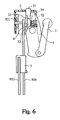
- a locking mechanism (or locking means) 1 of a frame unit 9 comprises a rectangular base 2, a blocking member 3, a wheel-shaped restricting member 4, a rectangular slide 5, a cover-like pivoting member 6, and a handle 7.
- the base 2 includes a first board 21, a second board 22 parallel to the first board 21, a U-shaped bridge board 23 connecting with the first board 21 and the second board 22, and a slot 24 defined by the first board 21 and the second board 22 and situated at three end surfaces of the first board 21 and the second board 22.
- the first board 21 has an aperture 211 formed at the center thereof, two L-shaped ribs 212 near a surface of the second board 22, and a slit 213 defined by the two ribs 212.
- the bridge board 23 has two aligned holes 231 respectively placed on the two opposite surfaces extending away from the first board, an opening 232 situated on the third surface, and two wedges, only one of which is shown in Fig. 3 .
- the two wedges respectively have an inclined surface 233.
- the two inclined surfaces 233 is spaced farther at the end near the opening 232 than the end away from the opening 232.
- the second board 22 has a bore 221 aligned with the aperture 211 of the first board 21.
- the slide 5 includes a first plate 51, a second plate 52 parallel to the first plate 51, a bridge plate 53 connecting the first plate 51 and the second plate 52, and a flute 54 defined by the first plate 51 and the second plate 52 and situated at three end surfaces of the first plate 51 and the second plate 52.
- the first plate 51 has a tunnel 511 defined by ribs on the surface near the second plate 52, two eyelets 512 whose central line is perpendicular to the axis of the tunnel 511, and a ledge 513 on the surface away from the second plate 52.
- the pivoting member 6 includes a perpendicular protrusion 61 at one end thereof, a perpendicular protuberance 62 at another end thereof, and a pivoting portion 64 constructed by two pivotal holes respectively situated at two sides of the pivoting member 6 near the middle part thereof
- the blocking member 3 includes a head 31, a tail 32 opposite to the head 31, two L-shaped elastic arms 33 perpendicularly protruding respectively from two sides thereof between the head 31 and the tails 32, a projection 34 perpendicular to the head 31 and the arms 33 between the head 31 and the tails 32.
- the tail 32 has an elongated hole 321.
- the restricting member 4 has an axial orifice 41 and a ring 42 around the circumference.
- the orifice 41 has different diameters at two opposite sections and a step (not shown) is formed at the intersection of the two sections.
- a pin 71 is pass through the two end holes of the handle 7 and the performation 63 of the pivoting member 6 to pivotally connect the handle 7 to the pivoting member 6.
- the blocking member 3 is installed into the base 2 in the manner that the head 31 of the blocking member 3 protrudes out of the opening 232 and the two arms 33 are respectively against the inclined surfaces 233 of the wedges in the base 2.
- the restricting member 4 is inserted at one end thereof into the elongated hole 321 of the blocking member 3 and a flexible member 72 such as a spring is bushed around another end of the restricting member 4.
- a rivet (not shown) is passed through the hole 231 of the base 2 and the pivotal holes 64 of the pivoting member 6 to pivotally connect the sub-assembly of the pivoting member 6 and the handle 7 to the base 2.
- a rivet (not shown) is passed through the hole 231 of the base 2 and the pivotal holes 64 of the pivoting member 6 to pivotally connect the sub-assembly of the pivoting member 6 and the handle 7 to the base 2.
- another end of the flexible member 72 is just bushed around the protrusion 61 of the pivoting member 6.
- the slide 5 is placed under the base 2 and by means that the force of restoration of the flexible member 72 situated at one end of the pivoting member 6 together with the abutment of the projection 34 of the locking member 3 against upper end of the pivoting member 6, the protuberance 62 situated at another end of the pivoting member 6 hooks onto the lower surface of the ledge 513 of the slide 5 to secure the slide 5 and to completely construct the locking means 1 for the frame unit 9 according to the present invention.
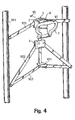
- the frame unit 9 applied together with the locking means 1 comprises a strut assembly 91, a rod assembly 92, and a pedal assembly 93.
- the strut assembly 91 includes a plurality of struts 911, which parallel to , inclined, or crossed each other to construct a stroller or a push-chair with a canopy (not shown), but only two struts 911 are shown in this embodiment.
- the rod assembly 92 includes two first rods 921, two second rods 922, two third rods 923, and a guiding rod 924.
- the pedal assembly 93 has a pedal body 931 and a collar 932 integrated with the pedal body 931.
- the pedal body 931 further has a recess 933 at the front end thereof and the collar 932 further has a howe 934 at the center thereof.
- the two first rods 921 at one end thereof are respectively connected pivotally to the two struts 911 by a rivet. Another ends of the two first rods 921 are respectively inserted into the slot 24 from two sides of the base 2 and one end of the guiding rod 924 is inserted into the slit 213 of the base 2.
- a rivet (not shown) is sequentially passed through the orifice 41 of the restricting member 4, the aperture 211 of the first board 21, the one end of the guiding rod 924, the another ends of the two first rods 921, and the bore 221 of the second board 22 and then the members mentioned above are pivotally connected together.
- One ends of two second rods 922 are respectively inserted into the flute 54 of the slide 5, and then pivotally connected to the slide 5 respectively at the eyelets 512 by a rivet.
- the another end of the guiding rod 924 is previously passed through the tunnel 511 of the slide 5 and the recess 933 of the pedal body 931, and then a rivet is sequentially passed through the howe 934 of the collar 932, the another end of the guiding rod 924, and the another ends of the third rods 923 in order to pivotally connect the pedal assembly 93, the guiding rod 924, and the third rods 923 together.
- the another end of each the second rod 922 and each the third rod 923 are pivotally connected to each the strut 911 respectively by a rivet.
- the protuberance 62 of the pivoting member 6 usually locking at the slide 5 by the aid of the flexible member 72 is served as a secondary safety lock which can prevent the slide 5 from departing from the upper end point of the guiding rod 924 to unexpectedly fold the rod assembly 92 and the frame unit 9 when the frame unit 9 is suffered an incidental force.
- the blocking member 3 has to be pressed down to separate the projection 34 from the upper end of the pivoting member 6.
- the restricting member 4 may abuts against the upper edge of the circumference of the elongated hole 321, which enables the restricting member 4 to prevent the blocking member 3 from being excessively pressed down.
- the upper end of the pivoting member 6 is pressed or the handle 7 is pulled upward with one hand, both of which can pivotally rotate the pivoting member 6 to separate the protuberance 62 from the ledge 513 and release the engagement of the pivoting member 6 and the slide 5.
- the state of the rod assembly 92 or the slide 5 situating at the upper dead point is released and the slide 5 is moved down and runs away from the base 2 along the guiding bar 924 to fold the frame unit 9.
- the pivoting member 6 is recovered to the previous state by the restoration force of the flexible member 72.
- the blocking member 3 is recovered to the state prior to be pressed by the component of force upwardly exerted on the elastic arms 33 applied by the inclined surfaces 233 of the wedges.
- the struts 911 may be oppositely pulled out each other by both hands in order to make the slide move upwardly to the extent that the ledge 513 is held by the protuberance 62 so that the pivoting member 6 is engaged with the slide 5.
- the pedal body 931 may be stepped on by one foot and the struts 911 may be oppositely pulled out each other by both hands, which is more easy to stretch the frame unit 9.
Landscapes
- Engineering & Computer Science (AREA)
- Chemical & Material Sciences (AREA)
- Combustion & Propulsion (AREA)
- Transportation (AREA)
- Mechanical Engineering (AREA)
- Carriages For Children, Sleds, And Other Hand-Operated Vehicles (AREA)
- Supporting Of Heads In Record-Carrier Devices (AREA)
- Door And Window Frames Mounted To Openings (AREA)
- Jib Cranes (AREA)
- Mirrors, Picture Frames, Photograph Stands, And Related Fastening Devices (AREA)
Claims (12)
- Rahmeneinheit (9) mit einer Feststellvorrichtung (1), wobei die Rahmeneinheit (9) mindestens eine erste Strebe (921) und mindestens eine zweite Strebe (922) aufweist, wobei die Feststellvorrichtung (1) umfasst:eine Basis (2), die schwenkbar mit der ersten Strebe (921) der Rahmeneinheit (9) verbunden ist;ein Schwenkelement (6), das gegenüberliegend zwei Enden, einen Schwenkbereich (64) zwischen den zwei Enden, und einen Vorsprung (62) an einem der beiden Enden aufweist, wobei der Schwenkbereich (64) schwenkbar mit der Basis (2) verbunden ist; undein flexibles Element (72), das zwischen dem Schwenkelement (6) und der Basis (2) zum Zurückstellen des Schwenkelements (6) vorgesehen ist;ein Gleitelement (5), das schwenkbar mit der zweiten Strebe (922) der Rahmeneinheit (9) verbunden ist; undwobei der Vorsprung (62) zum Feststellen des Gleitelements (5) bereitgestellt wird, um das Gleitelement (5) nahe der Basis (2) zu befestigen und die erste Strebe (921) und die zweite Strebe (922) der Rahmeneinheit (9) in einem aufgespannten Zustand zu halten,dadurch gekennzeichnet, dass
ein Blockierelement (3) in der Basis (2) zum Kontaktieren des Schwenkelements (6) angeordnet ist, um das Schwenkelement (6) an einem Trennen von dem Gleitelement (5) zu hindern;
wobei das Schwenkelement (6), wenn das Blockierelement (3) relativ zu dem Schwenkelement (6) bewegt wird und eine Kraft auf ein Ende des Schwenkelements (6) aufgebracht wird, relativ zu dem Schwenkbereich (64) schwenkend gedreht wird, so dass der Vorsprung (62) des Schwenkelements (6) von dem Gleitelement (5) getrennt wird, um dem Gleitelement (5) zu ermöglichen, sich relativ zu der Basis (2) zu bewegen, welches die Rahmeneinheit (9), die erste Strebe (921) und die zweite Strebe (922) in einen faltbaren Zustand bringt. - Rahmeneinheit (9) mit der Feststellvorrichtung (1) nach Anspruch 1, wobei das Blockierelement (3) zwei elastische Arme (33) aufweist, und die Basis (2) zwei geneigte Flächen (233) aufweist, die die zwei elastischen Arme (33) jeweils kontaktieren, um das Blockierelement (3) zurückzustellen.
- Rahmeneinheit (9) mit der Feststellvorrichtung (1) nach Anspruch 1 oder 2, wobei die Feststellvorrichtung (1) des weiteren ein Beschränkungselement (4) aufweist, und das Blockierelement (3) des Weiteren ein Langloch (321) zum Aufnehmen des Beschränkungselements (4) aufweist, welches das Blockierelement (3) und das flexible Element (72) auf einen Bereich beschränkt.
- Rahmeneinheit (9) mit der Feststellvorrichtung (1) nach einem der Ansprüche 1-3, wobei die Feststellvorrichtung (1) des Weiteren einen Griff (7) aufweist, der an dem Schwenkelement (6) vorgesehen ist, und wobei der Vorsprung (62) von dem Gleitelement (5) getrennt wird, wenn eine Kraft auf den Griff (7) aufgebracht wird.
- Rahmeneinheit (9) mit der Feststellvorrichtung (1) nach einem der Ansprüche 1-4, wobei die Rahmeneinheit (9) des Weiteren eine Führungsstrebe (924) umfasst, die mit der Basis (2) zum Führen der Bewegung des Gleitelements (5) verbunden ist.
- Rahmeneinheit (9) mit der Feststellvorrichtung (1) nach Anspruch 5, wobei die Rahmeneinheit (9) des Weiteren eine Pedalanordnung (93) umfasst, die an einem Ende der Führungsstrebe (924) vorgesehen ist, um ein Aufspannen der Rahmeneinheit (9) zu vereinfachen.
- Rahmeneinheit (9) mit der Feststellvorrichtung (1) nach Anspruch 5 oder 6, wobei die Rahmeneinheit (9) des Weiteren mindestens eine dritte Strebe (923) zum Verbinden der Führungsstrebe (924) und der zweiten Strebe (922) umfasst.
- Rahmeneinheit (9) mit der Feststellvorrichtung (1) nach einem der Ansprüche 5-7, wobei die Basis (2) einen Schlitz (213) zum Aufnehmen der Führungsstrebe (924) aufweist.
- Rahmeneinheit (9) mit der Feststellvorrichtung (1) nach einem der Ansprüche 5-8, wobei das Gleitelement (5) einen Tunnel (511) zum Aufnehmen der Führungsstrebe (924) aufweist.
- Rahmeneinheit (9) mit der Feststellvorrichtung (1) nach einem der Ansprüche 1-9, wobei die Rahmeneinheit (9) des Weiteren eine Strebenanordnung (92) umfasst, die die erste Strebe (921) und die zweite Strebe (922) verbindet.
- Rahmeneinheit (9) mit der Feststellvorrichtung (1) nach einem der Ansprüche 1-10, wobei die Basis (2) mindestens eine Aussparung (24) zum Aufnehmen von mindestens der ersten Strebe (921) aufweist.
- Rahmeneinheit (9) mit der Feststellvorrichtung (1) nach einem der Ansprüche 1-11, wobei das Gleitelement (5) mindestens eine Nut (54) zum Aufnehmen der zweiten Strebe (922) aufweist.
Priority Applications (3)
| Application Number | Priority Date | Filing Date | Title |
|---|---|---|---|
| DE602004014096T DE602004014096D1 (de) | 2004-02-11 | 2004-02-11 | Schliessmechanismus für Rahmen |
| EP04003052A EP1564106B1 (de) | 2004-02-11 | 2004-02-11 | Schliessmechanismus für Rahmen |
| AT04003052T ATE396904T1 (de) | 2004-02-11 | 2004-02-11 | Schliessmechanismus für rahmen |
Applications Claiming Priority (1)
| Application Number | Priority Date | Filing Date | Title |
|---|---|---|---|
| EP04003052A EP1564106B1 (de) | 2004-02-11 | 2004-02-11 | Schliessmechanismus für Rahmen |
Publications (2)
| Publication Number | Publication Date |
|---|---|
| EP1564106A1 EP1564106A1 (de) | 2005-08-17 |
| EP1564106B1 true EP1564106B1 (de) | 2008-05-28 |
Family
ID=34684668
Family Applications (1)
| Application Number | Title | Priority Date | Filing Date |
|---|---|---|---|
| EP04003052A Expired - Lifetime EP1564106B1 (de) | 2004-02-11 | 2004-02-11 | Schliessmechanismus für Rahmen |
Country Status (3)
| Country | Link |
|---|---|
| EP (1) | EP1564106B1 (de) |
| AT (1) | ATE396904T1 (de) |
| DE (1) | DE602004014096D1 (de) |
Families Citing this family (4)
| Publication number | Priority date | Publication date | Assignee | Title |
|---|---|---|---|---|
| CN2784275Y (zh) * | 2005-06-17 | 2006-05-31 | 明门实业股份有限公司 | 供一支架单元用的锁固装置 |
| GB2441750B (en) * | 2006-09-15 | 2008-11-26 | Wonderland Nursery Goods | Safety device of collapsible stroller |
| FR2938813B1 (fr) * | 2008-11-24 | 2010-12-03 | Dorel France Sa | Chassis pliant de poussette pour enfant, et poussette correspondante |
| CN102689645B (zh) * | 2011-03-23 | 2014-05-28 | 明门香港股份有限公司 | 婴儿车及其车架收合机构 |
Family Cites Families (3)
| Publication number | Priority date | Publication date | Assignee | Title |
|---|---|---|---|---|
| DE9318000U1 (de) * | 1993-11-24 | 1994-02-03 | Chern Yng Enterprise Co. Ltd., Tainan | Klappmechanismus für Kinderwagen |
| DE19852050C2 (de) * | 1998-11-11 | 2003-06-18 | Link Treasure Ltd | Freigabevorrichtung für einen klappbaren Kinderwagen |
| ITVR20010022A1 (it) * | 2001-02-20 | 2002-08-20 | Inglesina Baby Spa L | Telaio ripiegabile ad ombrello particolarmente per passeggini |
-
2004
- 2004-02-11 EP EP04003052A patent/EP1564106B1/de not_active Expired - Lifetime
- 2004-02-11 DE DE602004014096T patent/DE602004014096D1/de not_active Expired - Lifetime
- 2004-02-11 AT AT04003052T patent/ATE396904T1/de not_active IP Right Cessation
Also Published As
| Publication number | Publication date |
|---|---|
| EP1564106A1 (de) | 2005-08-17 |
| ATE396904T1 (de) | 2008-06-15 |
| DE602004014096D1 (de) | 2008-07-10 |
Similar Documents
| Publication | Publication Date | Title |
|---|---|---|
| US6565111B2 (en) | Folding pushchair with tilting handle equipped with a folding control on the handle | |
| US7731220B2 (en) | Frame assembly for double-seat baby stroller | |
| US6443479B2 (en) | Locking device with safety arrangement for collapsable stroller | |
| US5871227A (en) | Foldable mechanism for use in a stroller | |
| US11066119B2 (en) | Folding scooter frame | |
| US6318392B1 (en) | Supportive walker with safety features | |
| JPS59106366A (ja) | ベビ−カ | |
| US6722690B2 (en) | Foldable strolier | |
| US6431567B2 (en) | Collapsible skateboard | |
| US5639109A (en) | Collapsible luggage trolley | |
| EP0994004A2 (de) | Verriegelungsvorrichtung für zusammenklappbare Kinderwagen | |
| US7178822B2 (en) | Stroller frame foldable in two directions | |
| US10773767B2 (en) | Folding drive mechanism of folding scooter | |
| US12233931B2 (en) | Vehicle frame and baby stroller | |
| US20020140193A1 (en) | Folding and locking arrangement for collapsible scooter | |
| US7735911B2 (en) | Collapsible high chair for children | |
| EP1564106B1 (de) | Schliessmechanismus für Rahmen | |
| EP1614605B1 (de) | Schliessmechanismus für Rahmen | |
| US5549311A (en) | Armrest and handle assembly for a stroller | |
| US7748782B2 (en) | Tilt adjustment mechanism for child safety seat | |
| EP1847439B1 (de) | Faltbarer Kinderwagen | |
| GB2445806A (en) | Locking pivot for baby stroller comprising blocking member | |
| US9700479B2 (en) | Foldable walker | |
| US7635159B2 (en) | Collapsing device and child seat using the same | |
| EP1733948B1 (de) | Verriegelungsvorrichtung zum Gebrauch in Kombination mit einer Rahmenstruktur |
Legal Events
| Date | Code | Title | Description |
|---|---|---|---|
| PUAI | Public reference made under article 153(3) epc to a published international application that has entered the european phase |
Free format text: ORIGINAL CODE: 0009012 |
|
| 17P | Request for examination filed |
Effective date: 20040824 |
|
| AK | Designated contracting states |
Kind code of ref document: A1 Designated state(s): AT BE BG CH CY CZ DE DK EE ES FI FR GB GR HU IE IT LI LU MC NL PT RO SE SI SK TR |
|
| AX | Request for extension of the european patent |
Extension state: AL LT LV MK |
|
| AKX | Designation fees paid |
Designated state(s): AT BE BG CH CY CZ DE DK EE ES FI FR GB GR HU IE IT LI LU MC NL PT RO SE SI SK TR |
|
| AXX | Extension fees paid |
Extension state: LT Payment date: 20040824 Extension state: AL Payment date: 20040824 Extension state: LV Payment date: 20040824 Extension state: MK Payment date: 20040824 |
|
| 17Q | First examination report despatched |
Effective date: 20070410 |
|
| RAP1 | Party data changed (applicant data changed or rights of an application transferred) |
Owner name: EXCELLERATE ENTERPRISE CO., LTD. |
|
| GRAP | Despatch of communication of intention to grant a patent |
Free format text: ORIGINAL CODE: EPIDOSNIGR1 |
|
| GRAS | Grant fee paid |
Free format text: ORIGINAL CODE: EPIDOSNIGR3 |
|
| GRAA | (expected) grant |
Free format text: ORIGINAL CODE: 0009210 |
|
| AK | Designated contracting states |
Kind code of ref document: B1 Designated state(s): AT BE BG CH CY CZ DE DK EE ES FI FR GB GR HU IE IT LI LU MC NL PT RO SE SI SK TR |
|
| AX | Request for extension of the european patent |
Extension state: AL LT LV MK |
|
| REG | Reference to a national code |
Ref country code: GB Ref legal event code: FG4D |
|
| REG | Reference to a national code |
Ref country code: CH Ref legal event code: EP |
|
| REF | Corresponds to: |
Ref document number: 602004014096 Country of ref document: DE Date of ref document: 20080710 Kind code of ref document: P |
|
| REG | Reference to a national code |
Ref country code: IE Ref legal event code: FG4D |
|
| PG25 | Lapsed in a contracting state [announced via postgrant information from national office to epo] |
Ref country code: SI Free format text: LAPSE BECAUSE OF FAILURE TO SUBMIT A TRANSLATION OF THE DESCRIPTION OR TO PAY THE FEE WITHIN THE PRESCRIBED TIME-LIMIT Effective date: 20080528 |
|
| PG25 | Lapsed in a contracting state [announced via postgrant information from national office to epo] |
Ref country code: ES Free format text: LAPSE BECAUSE OF FAILURE TO SUBMIT A TRANSLATION OF THE DESCRIPTION OR TO PAY THE FEE WITHIN THE PRESCRIBED TIME-LIMIT Effective date: 20080908 Ref country code: FI Free format text: LAPSE BECAUSE OF FAILURE TO SUBMIT A TRANSLATION OF THE DESCRIPTION OR TO PAY THE FEE WITHIN THE PRESCRIBED TIME-LIMIT Effective date: 20080528 |
|
| PG25 | Lapsed in a contracting state [announced via postgrant information from national office to epo] |
Ref country code: AT Free format text: LAPSE BECAUSE OF FAILURE TO SUBMIT A TRANSLATION OF THE DESCRIPTION OR TO PAY THE FEE WITHIN THE PRESCRIBED TIME-LIMIT Effective date: 20080528 Ref country code: NL Free format text: LAPSE BECAUSE OF FAILURE TO SUBMIT A TRANSLATION OF THE DESCRIPTION OR TO PAY THE FEE WITHIN THE PRESCRIBED TIME-LIMIT Effective date: 20080528 |
|
| NLV1 | Nl: lapsed or annulled due to failure to fulfill the requirements of art. 29p and 29m of the patents act | ||
| PG25 | Lapsed in a contracting state [announced via postgrant information from national office to epo] |
Ref country code: DK Free format text: LAPSE BECAUSE OF FAILURE TO SUBMIT A TRANSLATION OF THE DESCRIPTION OR TO PAY THE FEE WITHIN THE PRESCRIBED TIME-LIMIT Effective date: 20080528 Ref country code: PT Free format text: LAPSE BECAUSE OF FAILURE TO SUBMIT A TRANSLATION OF THE DESCRIPTION OR TO PAY THE FEE WITHIN THE PRESCRIBED TIME-LIMIT Effective date: 20081028 Ref country code: CZ Free format text: LAPSE BECAUSE OF FAILURE TO SUBMIT A TRANSLATION OF THE DESCRIPTION OR TO PAY THE FEE WITHIN THE PRESCRIBED TIME-LIMIT Effective date: 20080528 Ref country code: SE Free format text: LAPSE BECAUSE OF FAILURE TO SUBMIT A TRANSLATION OF THE DESCRIPTION OR TO PAY THE FEE WITHIN THE PRESCRIBED TIME-LIMIT Effective date: 20080828 |
|
| PG25 | Lapsed in a contracting state [announced via postgrant information from national office to epo] |
Ref country code: SK Free format text: LAPSE BECAUSE OF FAILURE TO SUBMIT A TRANSLATION OF THE DESCRIPTION OR TO PAY THE FEE WITHIN THE PRESCRIBED TIME-LIMIT Effective date: 20080528 Ref country code: BE Free format text: LAPSE BECAUSE OF FAILURE TO SUBMIT A TRANSLATION OF THE DESCRIPTION OR TO PAY THE FEE WITHIN THE PRESCRIBED TIME-LIMIT Effective date: 20080528 Ref country code: RO Free format text: LAPSE BECAUSE OF FAILURE TO SUBMIT A TRANSLATION OF THE DESCRIPTION OR TO PAY THE FEE WITHIN THE PRESCRIBED TIME-LIMIT Effective date: 20080528 |
|
| PLBE | No opposition filed within time limit |
Free format text: ORIGINAL CODE: 0009261 |
|
| STAA | Information on the status of an ep patent application or granted ep patent |
Free format text: STATUS: NO OPPOSITION FILED WITHIN TIME LIMIT |
|
| PG25 | Lapsed in a contracting state [announced via postgrant information from national office to epo] |
Ref country code: EE Free format text: LAPSE BECAUSE OF FAILURE TO SUBMIT A TRANSLATION OF THE DESCRIPTION OR TO PAY THE FEE WITHIN THE PRESCRIBED TIME-LIMIT Effective date: 20080528 Ref country code: BG Free format text: LAPSE BECAUSE OF FAILURE TO SUBMIT A TRANSLATION OF THE DESCRIPTION OR TO PAY THE FEE WITHIN THE PRESCRIBED TIME-LIMIT Effective date: 20080828 |
|
| 26N | No opposition filed |
Effective date: 20090303 |
|
| PG25 | Lapsed in a contracting state [announced via postgrant information from national office to epo] |
Ref country code: MC Free format text: LAPSE BECAUSE OF NON-PAYMENT OF DUE FEES Effective date: 20090228 |
|
| REG | Reference to a national code |
Ref country code: CH Ref legal event code: PL |
|
| PG25 | Lapsed in a contracting state [announced via postgrant information from national office to epo] |
Ref country code: LI Free format text: LAPSE BECAUSE OF NON-PAYMENT OF DUE FEES Effective date: 20090228 Ref country code: CH Free format text: LAPSE BECAUSE OF NON-PAYMENT OF DUE FEES Effective date: 20090228 |
|
| REG | Reference to a national code |
Ref country code: IE Ref legal event code: MM4A |
|
| PG25 | Lapsed in a contracting state [announced via postgrant information from national office to epo] |
Ref country code: IE Free format text: LAPSE BECAUSE OF NON-PAYMENT OF DUE FEES Effective date: 20090211 |
|
| PG25 | Lapsed in a contracting state [announced via postgrant information from national office to epo] |
Ref country code: GR Free format text: LAPSE BECAUSE OF FAILURE TO SUBMIT A TRANSLATION OF THE DESCRIPTION OR TO PAY THE FEE WITHIN THE PRESCRIBED TIME-LIMIT Effective date: 20080829 |
|
| PG25 | Lapsed in a contracting state [announced via postgrant information from national office to epo] |
Ref country code: LU Free format text: LAPSE BECAUSE OF NON-PAYMENT OF DUE FEES Effective date: 20090211 |
|
| PG25 | Lapsed in a contracting state [announced via postgrant information from national office to epo] |
Ref country code: HU Free format text: LAPSE BECAUSE OF FAILURE TO SUBMIT A TRANSLATION OF THE DESCRIPTION OR TO PAY THE FEE WITHIN THE PRESCRIBED TIME-LIMIT Effective date: 20081129 |
|
| PG25 | Lapsed in a contracting state [announced via postgrant information from national office to epo] |
Ref country code: TR Free format text: LAPSE BECAUSE OF FAILURE TO SUBMIT A TRANSLATION OF THE DESCRIPTION OR TO PAY THE FEE WITHIN THE PRESCRIBED TIME-LIMIT Effective date: 20080528 |
|
| PG25 | Lapsed in a contracting state [announced via postgrant information from national office to epo] |
Ref country code: CY Free format text: LAPSE BECAUSE OF FAILURE TO SUBMIT A TRANSLATION OF THE DESCRIPTION OR TO PAY THE FEE WITHIN THE PRESCRIBED TIME-LIMIT Effective date: 20080528 |
|
| REG | Reference to a national code |
Ref country code: DE Ref legal event code: R082 Ref document number: 602004014096 Country of ref document: DE Representative=s name: PATENT- UND RECHTSANWAELTE KRAUS & WEISERT, DE |
|
| REG | Reference to a national code |
Ref country code: DE Ref legal event code: R082 Ref document number: 602004014096 Country of ref document: DE Representative=s name: PATENT- UND RECHTSANWAELTE KRAUS & WEISERT, DE Effective date: 20130927 Ref country code: DE Ref legal event code: R081 Ref document number: 602004014096 Country of ref document: DE Owner name: BP CHILDREN'S PRODUCTS HK CO., LIMITED, HK Free format text: FORMER OWNER: EXCELLERATE ENTERPRISE CO., LTD., TAIPEI, TW Effective date: 20130927 Ref country code: DE Ref legal event code: R081 Ref document number: 602004014096 Country of ref document: DE Owner name: BP CHILDREN'S PRODUCTS HK CO., LIMITED, KWUN T, HK Free format text: FORMER OWNER: EXCELLERATE ENTERPRISE CO., LTD., TAIPEI, TW Effective date: 20130927 Ref country code: DE Ref legal event code: R082 Ref document number: 602004014096 Country of ref document: DE Representative=s name: KRAUS & WEISERT PATENTANWAELTE PARTGMBB, DE Effective date: 20130927 |
|
| REG | Reference to a national code |
Ref country code: FR Ref legal event code: TP Owner name: BP CHILDREN'S PRODUCTS HK CO., LIMITED, HK Effective date: 20131210 |
|
| REG | Reference to a national code |
Ref country code: GB Ref legal event code: 732E Free format text: REGISTERED BETWEEN 20140116 AND 20140122 |
|
| REG | Reference to a national code |
Ref country code: FR Ref legal event code: PLFP Year of fee payment: 13 |
|
| REG | Reference to a national code |
Ref country code: FR Ref legal event code: PLFP Year of fee payment: 14 |
|
| REG | Reference to a national code |
Ref country code: FR Ref legal event code: PLFP Year of fee payment: 15 |
|
| REG | Reference to a national code |
Ref country code: GB Ref legal event code: 732E Free format text: REGISTERED BETWEEN 20180809 AND 20180815 |
|
| REG | Reference to a national code |
Ref country code: DE Ref legal event code: R082 Ref document number: 602004014096 Country of ref document: DE Representative=s name: KRAUS & WEISERT PATENTANWAELTE PARTGMBB, DE Ref country code: DE Ref legal event code: R081 Ref document number: 602004014096 Country of ref document: DE Owner name: BAMBINO PREZIOSO SWITZERLAND AG, CH Free format text: FORMER OWNER: BP CHILDREN'S PRODUCTS HK CO., LIMITED, KWUN TONG, KOWLOON, HK |
|
| PGFP | Annual fee paid to national office [announced via postgrant information from national office to epo] |
Ref country code: GB Payment date: 20221222 Year of fee payment: 20 Ref country code: FR Payment date: 20221229 Year of fee payment: 20 |
|
| PGFP | Annual fee paid to national office [announced via postgrant information from national office to epo] |
Ref country code: IT Payment date: 20230220 Year of fee payment: 20 Ref country code: DE Payment date: 20221220 Year of fee payment: 20 |
|
| P01 | Opt-out of the competence of the unified patent court (upc) registered |
Effective date: 20230522 |
|
| REG | Reference to a national code |
Ref country code: DE Ref legal event code: R071 Ref document number: 602004014096 Country of ref document: DE |
|
| REG | Reference to a national code |
Ref country code: GB Ref legal event code: PE20 Expiry date: 20240210 |
|
| PG25 | Lapsed in a contracting state [announced via postgrant information from national office to epo] |
Ref country code: GB Free format text: LAPSE BECAUSE OF EXPIRATION OF PROTECTION Effective date: 20240210 |