EP1564020B1 - Printing plate precursor material - Google Patents
Printing plate precursor material Download PDFInfo
- Publication number
- EP1564020B1 EP1564020B1 EP05100873A EP05100873A EP1564020B1 EP 1564020 B1 EP1564020 B1 EP 1564020B1 EP 05100873 A EP05100873 A EP 05100873A EP 05100873 A EP05100873 A EP 05100873A EP 1564020 B1 EP1564020 B1 EP 1564020B1
- Authority
- EP
- European Patent Office
- Prior art keywords
- image formation
- particles
- printing plate
- formation layer
- weight
- Prior art date
- Legal status (The legal status is an assumption and is not a legal conclusion. Google has not performed a legal analysis and makes no representation as to the accuracy of the status listed.)
- Ceased
Links
- 238000007639 printing Methods 0.000 title claims description 148
- 239000000463 material Substances 0.000 title claims description 108
- 239000002243 precursor Substances 0.000 title description 5
- 239000002245 particle Substances 0.000 claims description 211
- 230000015572 biosynthetic process Effects 0.000 claims description 102
- 229920005992 thermoplastic resin Polymers 0.000 claims description 76
- XLYOFNOQVPJJNP-UHFFFAOYSA-N water Substances O XLYOFNOQVPJJNP-UHFFFAOYSA-N 0.000 claims description 53
- 229920005989 resin Polymers 0.000 claims description 41
- 239000011347 resin Substances 0.000 claims description 41
- 239000011248 coating agent Substances 0.000 claims description 36
- 238000000576 coating method Methods 0.000 claims description 36
- 238000000034 method Methods 0.000 claims description 32
- 238000006243 chemical reaction Methods 0.000 claims description 20
- 230000009477 glass transition Effects 0.000 claims description 13
- 238000001035 drying Methods 0.000 claims description 12
- 150000004676 glycans Chemical class 0.000 claims description 11
- 229920001282 polysaccharide Chemical class 0.000 claims description 11
- 239000005017 polysaccharide Chemical class 0.000 claims description 11
- 229920002125 Sokalan® Chemical class 0.000 claims description 10
- 239000004584 polyacrylic acid Chemical class 0.000 claims description 10
- 229920001169 thermoplastic Polymers 0.000 claims description 10
- 150000003839 salts Chemical class 0.000 claims description 9
- 229920000728 polyester Polymers 0.000 claims description 8
- 239000004416 thermosoftening plastic Substances 0.000 claims description 8
- 229920002401 polyacrylamide Polymers 0.000 claims description 6
- 229920001542 oligosaccharide Polymers 0.000 claims description 5
- 150000002482 oligosaccharides Chemical class 0.000 claims description 5
- 230000008569 process Effects 0.000 claims description 5
- 238000004519 manufacturing process Methods 0.000 claims description 4
- 239000010410 layer Substances 0.000 description 156
- 238000011282 treatment Methods 0.000 description 74
- 239000000243 solution Substances 0.000 description 65
- VYPSYNLAJGMNEJ-UHFFFAOYSA-N Silicium dioxide Chemical compound O=[Si]=O VYPSYNLAJGMNEJ-UHFFFAOYSA-N 0.000 description 40
- 229910052782 aluminium Inorganic materials 0.000 description 39
- XAGFODPZIPBFFR-UHFFFAOYSA-N aluminium Chemical compound [Al] XAGFODPZIPBFFR-UHFFFAOYSA-N 0.000 description 37
- 229910044991 metal oxide Inorganic materials 0.000 description 33
- 150000004706 metal oxides Chemical group 0.000 description 33
- 238000007788 roughening Methods 0.000 description 31
- NBIIXXVUZAFLBC-UHFFFAOYSA-N Phosphoric acid Chemical compound OP(O)(O)=O NBIIXXVUZAFLBC-UHFFFAOYSA-N 0.000 description 22
- HEMHJVSKTPXQMS-UHFFFAOYSA-M Sodium hydroxide Chemical compound [OH-].[Na+] HEMHJVSKTPXQMS-UHFFFAOYSA-M 0.000 description 21
- QAOWNCQODCNURD-UHFFFAOYSA-N Sulfuric acid Chemical compound OS(O)(=O)=O QAOWNCQODCNURD-UHFFFAOYSA-N 0.000 description 20
- 239000008119 colloidal silica Substances 0.000 description 20
- 239000002253 acid Substances 0.000 description 17
- 239000003513 alkali Substances 0.000 description 17
- VEXZGXHMUGYJMC-UHFFFAOYSA-N Hydrochloric acid Chemical compound Cl VEXZGXHMUGYJMC-UHFFFAOYSA-N 0.000 description 16
- 239000007864 aqueous solution Substances 0.000 description 15
- 239000007787 solid Substances 0.000 description 15
- 239000006185 dispersion Substances 0.000 description 14
- 239000000839 emulsion Substances 0.000 description 14
- 238000011109 contamination Methods 0.000 description 13
- 238000011161 development Methods 0.000 description 13
- 230000018109 developmental process Effects 0.000 description 13
- 239000008151 electrolyte solution Substances 0.000 description 13
- 238000005530 etching Methods 0.000 description 13
- 238000006386 neutralization reaction Methods 0.000 description 13
- -1 polyethylene terephthalate Polymers 0.000 description 13
- KWYUFKZDYYNOTN-UHFFFAOYSA-M Potassium hydroxide Chemical compound [OH-].[K+] KWYUFKZDYYNOTN-UHFFFAOYSA-M 0.000 description 12
- 229910052751 metal Inorganic materials 0.000 description 12
- 239000002184 metal Substances 0.000 description 12
- 229910000147 aluminium phosphate Inorganic materials 0.000 description 11
- 238000002048 anodisation reaction Methods 0.000 description 11
- 238000005238 degreasing Methods 0.000 description 11
- HNPSIPDUKPIQMN-UHFFFAOYSA-N dioxosilane;oxo(oxoalumanyloxy)alumane Chemical compound O=[Si]=O.O=[Al]O[Al]=O HNPSIPDUKPIQMN-UHFFFAOYSA-N 0.000 description 11
- 239000007788 liquid Substances 0.000 description 11
- 229920000642 polymer Polymers 0.000 description 10
- QTBSBXVTEAMEQO-UHFFFAOYSA-N Acetic acid Chemical compound CC(O)=O QTBSBXVTEAMEQO-UHFFFAOYSA-N 0.000 description 9
- GRYLNZFGIOXLOG-UHFFFAOYSA-N Nitric acid Chemical compound O[N+]([O-])=O GRYLNZFGIOXLOG-UHFFFAOYSA-N 0.000 description 9
- 239000000975 dye Substances 0.000 description 9
- SZVJSHCCFOBDDC-UHFFFAOYSA-N iron(II,III) oxide Inorganic materials O=[Fe]O[Fe]O[Fe]=O SZVJSHCCFOBDDC-UHFFFAOYSA-N 0.000 description 9
- 239000000203 mixture Substances 0.000 description 9
- 229910017604 nitric acid Inorganic materials 0.000 description 9
- 229920001225 polyester resin Polymers 0.000 description 9
- 239000004645 polyester resin Substances 0.000 description 9
- GWEVSGVZZGPLCZ-UHFFFAOYSA-N Titan oxide Chemical compound O=[Ti]=O GWEVSGVZZGPLCZ-UHFFFAOYSA-N 0.000 description 8
- 238000010438 heat treatment Methods 0.000 description 8
- 239000011148 porous material Substances 0.000 description 8
- 239000004094 surface-active agent Substances 0.000 description 8
- 229910000323 aluminium silicate Inorganic materials 0.000 description 7
- WTFXARWRTYJXII-UHFFFAOYSA-N iron(2+);iron(3+);oxygen(2-) Chemical compound [O-2].[O-2].[O-2].[O-2].[Fe+2].[Fe+3].[Fe+3] WTFXARWRTYJXII-UHFFFAOYSA-N 0.000 description 7
- 239000002904 solvent Substances 0.000 description 7
- OKTJSMMVPCPJKN-UHFFFAOYSA-N Carbon Chemical compound [C] OKTJSMMVPCPJKN-UHFFFAOYSA-N 0.000 description 6
- 229920000459 Nitrile rubber Polymers 0.000 description 6
- BPQQTUXANYXVAA-UHFFFAOYSA-N Orthosilicate Chemical compound [O-][Si]([O-])([O-])[O-] BPQQTUXANYXVAA-UHFFFAOYSA-N 0.000 description 6
- MUBZPKHOEPUJKR-UHFFFAOYSA-N Oxalic acid Chemical compound OC(=O)C(O)=O MUBZPKHOEPUJKR-UHFFFAOYSA-N 0.000 description 6
- CDBYLPFSWZWCQE-UHFFFAOYSA-L Sodium Carbonate Chemical compound [Na+].[Na+].[O-]C([O-])=O CDBYLPFSWZWCQE-UHFFFAOYSA-L 0.000 description 6
- 239000001768 carboxy methyl cellulose Substances 0.000 description 6
- KRVSOGSZCMJSLX-UHFFFAOYSA-L chromic acid Substances O[Cr](O)(=O)=O KRVSOGSZCMJSLX-UHFFFAOYSA-L 0.000 description 6
- 230000005611 electricity Effects 0.000 description 6
- AWJWCTOOIBYHON-UHFFFAOYSA-N furo[3,4-b]pyrazine-5,7-dione Chemical compound C1=CN=C2C(=O)OC(=O)C2=N1 AWJWCTOOIBYHON-UHFFFAOYSA-N 0.000 description 6
- 239000004816 latex Substances 0.000 description 6
- 229920000126 latex Polymers 0.000 description 6
- NBIIXXVUZAFLBC-UHFFFAOYSA-K phosphate Chemical compound [O-]P([O-])([O-])=O NBIIXXVUZAFLBC-UHFFFAOYSA-K 0.000 description 6
- 239000000377 silicon dioxide Substances 0.000 description 6
- 239000001488 sodium phosphate Substances 0.000 description 6
- 229910000162 sodium phosphate Inorganic materials 0.000 description 6
- 229920002134 Carboxymethyl cellulose Polymers 0.000 description 5
- XEEYBQQBJWHFJM-UHFFFAOYSA-N Iron Chemical compound [Fe] XEEYBQQBJWHFJM-UHFFFAOYSA-N 0.000 description 5
- 229910019142 PO4 Inorganic materials 0.000 description 5
- 235000010948 carboxy methyl cellulose Nutrition 0.000 description 5
- 239000008112 carboxymethyl-cellulose Substances 0.000 description 5
- 229920002678 cellulose Polymers 0.000 description 5
- 230000005660 hydrophilic surface Effects 0.000 description 5
- 238000002844 melting Methods 0.000 description 5
- 230000008018 melting Effects 0.000 description 5
- 239000010452 phosphate Substances 0.000 description 5
- 238000002360 preparation method Methods 0.000 description 5
- 239000011241 protective layer Substances 0.000 description 5
- 239000000126 substance Substances 0.000 description 5
- 238000004381 surface treatment Methods 0.000 description 5
- RYFMWSXOAZQYPI-UHFFFAOYSA-K trisodium phosphate Chemical compound [Na+].[Na+].[Na+].[O-]P([O-])([O-])=O RYFMWSXOAZQYPI-UHFFFAOYSA-K 0.000 description 5
- PLXMOAALOJOTIY-FPTXNFDTSA-N Aesculin Natural products OC[C@@H]1[C@@H](O)[C@H](O)[C@@H](O)[C@H](O)[C@H]1Oc2cc3C=CC(=O)Oc3cc2O PLXMOAALOJOTIY-FPTXNFDTSA-N 0.000 description 4
- KRHYYFGTRYWZRS-UHFFFAOYSA-N Fluorane Chemical compound F KRHYYFGTRYWZRS-UHFFFAOYSA-N 0.000 description 4
- 239000002202 Polyethylene glycol Substances 0.000 description 4
- 230000002378 acidificating effect Effects 0.000 description 4
- 125000002091 cationic group Chemical group 0.000 description 4
- 235000010980 cellulose Nutrition 0.000 description 4
- 229920001223 polyethylene glycol Polymers 0.000 description 4
- 238000007789 sealing Methods 0.000 description 4
- 229910052710 silicon Inorganic materials 0.000 description 4
- 229920003048 styrene butadiene rubber Polymers 0.000 description 4
- 206010016807 Fluid retention Diseases 0.000 description 3
- DGAQECJNVWCQMB-PUAWFVPOSA-M Ilexoside XXIX Chemical compound C[C@@H]1CC[C@@]2(CC[C@@]3(C(=CC[C@H]4[C@]3(CC[C@@H]5[C@@]4(CC[C@@H](C5(C)C)OS(=O)(=O)[O-])C)C)[C@@H]2[C@]1(C)O)C)C(=O)O[C@H]6[C@@H]([C@H]([C@@H]([C@H](O6)CO)O)O)O.[Na+] DGAQECJNVWCQMB-PUAWFVPOSA-M 0.000 description 3
- PXHVJJICTQNCMI-UHFFFAOYSA-N Nickel Chemical compound [Ni] PXHVJJICTQNCMI-UHFFFAOYSA-N 0.000 description 3
- XUIMIQQOPSSXEZ-UHFFFAOYSA-N Silicon Chemical compound [Si] XUIMIQQOPSSXEZ-UHFFFAOYSA-N 0.000 description 3
- RTAQQCXQSZGOHL-UHFFFAOYSA-N Titanium Chemical compound [Ti] RTAQQCXQSZGOHL-UHFFFAOYSA-N 0.000 description 3
- PNEYBMLMFCGWSK-UHFFFAOYSA-N aluminium oxide Inorganic materials [O-2].[O-2].[O-2].[Al+3].[Al+3] PNEYBMLMFCGWSK-UHFFFAOYSA-N 0.000 description 3
- 239000011230 binding agent Substances 0.000 description 3
- 230000008859 change Effects 0.000 description 3
- KRKNYBCHXYNGOX-UHFFFAOYSA-N citric acid Chemical compound OC(=O)CC(O)(C(O)=O)CC(O)=O KRKNYBCHXYNGOX-UHFFFAOYSA-N 0.000 description 3
- 229910052681 coesite Inorganic materials 0.000 description 3
- 239000000084 colloidal system Substances 0.000 description 3
- 150000001875 compounds Chemical class 0.000 description 3
- 229910052906 cristobalite Inorganic materials 0.000 description 3
- 230000007423 decrease Effects 0.000 description 3
- 239000002270 dispersing agent Substances 0.000 description 3
- 238000005868 electrolysis reaction Methods 0.000 description 3
- 238000011156 evaluation Methods 0.000 description 3
- 230000002209 hydrophobic effect Effects 0.000 description 3
- 238000003384 imaging method Methods 0.000 description 3
- 229910052742 iron Inorganic materials 0.000 description 3
- 239000011572 manganese Substances 0.000 description 3
- 239000003960 organic solvent Substances 0.000 description 3
- 239000011734 sodium Substances 0.000 description 3
- 229910052708 sodium Inorganic materials 0.000 description 3
- 229910000029 sodium carbonate Inorganic materials 0.000 description 3
- 238000003980 solgel method Methods 0.000 description 3
- 238000003756 stirring Methods 0.000 description 3
- 229910052682 stishovite Inorganic materials 0.000 description 3
- 238000003860 storage Methods 0.000 description 3
- 230000003746 surface roughness Effects 0.000 description 3
- 239000010936 titanium Substances 0.000 description 3
- 229910052719 titanium Inorganic materials 0.000 description 3
- 229910052905 tridymite Inorganic materials 0.000 description 3
- HDTRYLNUVZCQOY-UHFFFAOYSA-N α-D-glucopyranosyl-α-D-glucopyranoside Natural products OC1C(O)C(O)C(CO)OC1OC1C(O)C(O)C(O)C(CO)O1 HDTRYLNUVZCQOY-UHFFFAOYSA-N 0.000 description 2
- 229910000838 Al alloy Inorganic materials 0.000 description 2
- USFZMSVCRYTOJT-UHFFFAOYSA-N Ammonium acetate Chemical compound N.CC(O)=O USFZMSVCRYTOJT-UHFFFAOYSA-N 0.000 description 2
- 239000005695 Ammonium acetate Substances 0.000 description 2
- BVKZGUZCCUSVTD-UHFFFAOYSA-M Bicarbonate Chemical compound OC([O-])=O BVKZGUZCCUSVTD-UHFFFAOYSA-M 0.000 description 2
- 229920001634 Copolyester Polymers 0.000 description 2
- 229910002551 Fe-Mn Inorganic materials 0.000 description 2
- 229920000663 Hydroxyethyl cellulose Chemical class 0.000 description 2
- 239000004354 Hydroxyethyl cellulose Chemical class 0.000 description 2
- 229920003171 Poly (ethylene oxide) Polymers 0.000 description 2
- 239000004372 Polyvinyl alcohol Substances 0.000 description 2
- 239000004373 Pullulan Substances 0.000 description 2
- 229920001218 Pullulan Polymers 0.000 description 2
- 239000004115 Sodium Silicate Substances 0.000 description 2
- 229920002472 Starch Polymers 0.000 description 2
- 239000002174 Styrene-butadiene Substances 0.000 description 2
- HDTRYLNUVZCQOY-WSWWMNSNSA-N Trehalose Natural products O[C@@H]1[C@@H](O)[C@@H](O)[C@@H](CO)O[C@@H]1O[C@@H]1[C@H](O)[C@@H](O)[C@@H](O)[C@@H](CO)O1 HDTRYLNUVZCQOY-WSWWMNSNSA-N 0.000 description 2
- 238000002679 ablation Methods 0.000 description 2
- 239000003082 abrasive agent Substances 0.000 description 2
- 239000000654 additive Substances 0.000 description 2
- 230000000996 additive effect Effects 0.000 description 2
- 230000032683 aging Effects 0.000 description 2
- 150000001299 aldehydes Chemical class 0.000 description 2
- 150000004703 alkoxides Chemical class 0.000 description 2
- HDTRYLNUVZCQOY-LIZSDCNHSA-N alpha,alpha-trehalose Chemical compound O[C@@H]1[C@@H](O)[C@H](O)[C@@H](CO)O[C@@H]1O[C@@H]1[C@H](O)[C@@H](O)[C@H](O)[C@@H](CO)O1 HDTRYLNUVZCQOY-LIZSDCNHSA-N 0.000 description 2
- 150000001412 amines Chemical class 0.000 description 2
- 229940043376 ammonium acetate Drugs 0.000 description 2
- 235000019257 ammonium acetate Nutrition 0.000 description 2
- 150000003863 ammonium salts Chemical class 0.000 description 2
- TZCXTZWJZNENPQ-UHFFFAOYSA-L barium sulfate Chemical compound [Ba+2].[O-]S([O-])(=O)=O TZCXTZWJZNENPQ-UHFFFAOYSA-L 0.000 description 2
- KGBXLFKZBHKPEV-UHFFFAOYSA-N boric acid Chemical compound OB(O)O KGBXLFKZBHKPEV-UHFFFAOYSA-N 0.000 description 2
- 239000004327 boric acid Substances 0.000 description 2
- 230000001680 brushing effect Effects 0.000 description 2
- MTAZNLWOLGHBHU-UHFFFAOYSA-N butadiene-styrene rubber Chemical compound C=CC=C.C=CC1=CC=CC=C1 MTAZNLWOLGHBHU-UHFFFAOYSA-N 0.000 description 2
- 229910052799 carbon Inorganic materials 0.000 description 2
- 150000001768 cations Chemical class 0.000 description 2
- 239000001913 cellulose Substances 0.000 description 2
- 239000003153 chemical reaction reagent Substances 0.000 description 2
- 239000003795 chemical substances by application Substances 0.000 description 2
- 150000001805 chlorine compounds Chemical class 0.000 description 2
- 229910052804 chromium Inorganic materials 0.000 description 2
- 239000011651 chromium Substances 0.000 description 2
- 230000021615 conjugation Effects 0.000 description 2
- 229920001577 copolymer Polymers 0.000 description 2
- 229910052802 copper Inorganic materials 0.000 description 2
- 239000010949 copper Substances 0.000 description 2
- GUJOJGAPFQRJSV-UHFFFAOYSA-N dialuminum;dioxosilane;oxygen(2-);hydrate Chemical compound O.[O-2].[O-2].[O-2].[Al+3].[Al+3].O=[Si]=O.O=[Si]=O.O=[Si]=O.O=[Si]=O GUJOJGAPFQRJSV-UHFFFAOYSA-N 0.000 description 2
- 150000001993 dienes Chemical class 0.000 description 2
- BNIILDVGGAEEIG-UHFFFAOYSA-L disodium hydrogen phosphate Chemical compound [Na+].[Na+].OP([O-])([O-])=O BNIILDVGGAEEIG-UHFFFAOYSA-L 0.000 description 2
- 238000004090 dissolution Methods 0.000 description 2
- 239000000428 dust Substances 0.000 description 2
- 230000000694 effects Effects 0.000 description 2
- 239000010419 fine particle Substances 0.000 description 2
- 229910052731 fluorine Inorganic materials 0.000 description 2
- 125000001153 fluoro group Chemical group F* 0.000 description 2
- 229910002804 graphite Inorganic materials 0.000 description 2
- 239000010439 graphite Substances 0.000 description 2
- UCNNJGDEJXIUCC-UHFFFAOYSA-L hydroxy(oxo)iron;iron Chemical compound [Fe].O[Fe]=O.O[Fe]=O UCNNJGDEJXIUCC-UHFFFAOYSA-L 0.000 description 2
- 235000019447 hydroxyethyl cellulose Nutrition 0.000 description 2
- 229910052500 inorganic mineral Inorganic materials 0.000 description 2
- 229920000592 inorganic polymer Polymers 0.000 description 2
- NLYAJNPCOHFWQQ-UHFFFAOYSA-N kaolin Chemical compound O.O.O=[Al]O[Si](=O)O[Si](=O)O[Al]=O NLYAJNPCOHFWQQ-UHFFFAOYSA-N 0.000 description 2
- 150000002739 metals Chemical class 0.000 description 2
- 239000011707 mineral Substances 0.000 description 2
- 229910052901 montmorillonite Inorganic materials 0.000 description 2
- 229910052759 nickel Inorganic materials 0.000 description 2
- 150000002823 nitrates Chemical class 0.000 description 2
- 239000003921 oil Substances 0.000 description 2
- 150000007524 organic acids Chemical class 0.000 description 2
- 235000006408 oxalic acid Nutrition 0.000 description 2
- 239000010893 paper waste Substances 0.000 description 2
- 150000004968 peroxymonosulfuric acids Chemical class 0.000 description 2
- 239000000049 pigment Substances 0.000 description 2
- 239000002985 plastic film Substances 0.000 description 2
- 229920006255 plastic film Polymers 0.000 description 2
- 229920001495 poly(sodium acrylate) polymer Polymers 0.000 description 2
- 229920001451 polypropylene glycol Polymers 0.000 description 2
- 229920002451 polyvinyl alcohol Polymers 0.000 description 2
- 229920001289 polyvinyl ether Polymers 0.000 description 2
- 229920000036 polyvinylpyrrolidone Polymers 0.000 description 2
- 239000001267 polyvinylpyrrolidone Substances 0.000 description 2
- 235000013855 polyvinylpyrrolidone Nutrition 0.000 description 2
- 239000011164 primary particle Substances 0.000 description 2
- 235000019423 pullulan Nutrition 0.000 description 2
- 238000010298 pulverizing process Methods 0.000 description 2
- 239000010703 silicon Substances 0.000 description 2
- 239000002002 slurry Substances 0.000 description 2
- NNMHYFLPFNGQFZ-UHFFFAOYSA-M sodium polyacrylate Chemical compound [Na+].[O-]C(=O)C=C NNMHYFLPFNGQFZ-UHFFFAOYSA-M 0.000 description 2
- 159000000000 sodium salts Chemical class 0.000 description 2
- 229910052911 sodium silicate Inorganic materials 0.000 description 2
- 239000012798 spherical particle Substances 0.000 description 2
- 238000010186 staining Methods 0.000 description 2
- 235000019698 starch Nutrition 0.000 description 2
- 239000011115 styrene butadiene Substances 0.000 description 2
- XOLBLPGZBRYERU-UHFFFAOYSA-N tin dioxide Chemical compound O=[Sn]=O XOLBLPGZBRYERU-UHFFFAOYSA-N 0.000 description 2
- OGIDPMRJRNCKJF-UHFFFAOYSA-N titanium oxide Inorganic materials [Ti]=O OGIDPMRJRNCKJF-UHFFFAOYSA-N 0.000 description 2
- 229920002554 vinyl polymer Polymers 0.000 description 2
- 229910052725 zinc Inorganic materials 0.000 description 2
- 239000011701 zinc Substances 0.000 description 2
- OWEGMIWEEQEYGQ-UHFFFAOYSA-N 100676-05-9 Natural products OC1C(O)C(O)C(CO)OC1OCC1C(O)C(O)C(O)C(OC2C(OC(O)C(O)C2O)CO)O1 OWEGMIWEEQEYGQ-UHFFFAOYSA-N 0.000 description 1
- VXEGSRKPIUDPQT-UHFFFAOYSA-N 4-[4-(4-methoxyphenyl)piperazin-1-yl]aniline Chemical compound C1=CC(OC)=CC=C1N1CCN(C=2C=CC(N)=CC=2)CC1 VXEGSRKPIUDPQT-UHFFFAOYSA-N 0.000 description 1
- 239000004925 Acrylic resin Substances 0.000 description 1
- GUBGYTABKSRVRQ-XLOQQCSPSA-N Alpha-Lactose Chemical compound O[C@@H]1[C@@H](O)[C@@H](O)[C@@H](CO)O[C@H]1O[C@@H]1[C@@H](CO)O[C@H](O)[C@H](O)[C@H]1O GUBGYTABKSRVRQ-XLOQQCSPSA-N 0.000 description 1
- VYZAMTAEIAYCRO-UHFFFAOYSA-N Chromium Chemical compound [Cr] VYZAMTAEIAYCRO-UHFFFAOYSA-N 0.000 description 1
- RYGMFSIKBFXOCR-UHFFFAOYSA-N Copper Chemical compound [Cu] RYGMFSIKBFXOCR-UHFFFAOYSA-N 0.000 description 1
- 235000002918 Fraxinus excelsior Nutrition 0.000 description 1
- UFHFLCQGNIYNRP-UHFFFAOYSA-N Hydrogen Chemical compound [H][H] UFHFLCQGNIYNRP-UHFFFAOYSA-N 0.000 description 1
- GUBGYTABKSRVRQ-QKKXKWKRSA-N Lactose Natural products OC[C@H]1O[C@@H](O[C@H]2[C@H](O)[C@@H](O)C(O)O[C@@H]2CO)[C@H](O)[C@@H](O)[C@H]1O GUBGYTABKSRVRQ-QKKXKWKRSA-N 0.000 description 1
- FYYHWMGAXLPEAU-UHFFFAOYSA-N Magnesium Chemical compound [Mg] FYYHWMGAXLPEAU-UHFFFAOYSA-N 0.000 description 1
- GUBGYTABKSRVRQ-PICCSMPSSA-N Maltose Natural products O[C@@H]1[C@@H](O)[C@H](O)[C@@H](CO)O[C@@H]1O[C@@H]1[C@@H](CO)OC(O)[C@H](O)[C@H]1O GUBGYTABKSRVRQ-PICCSMPSSA-N 0.000 description 1
- 229930192627 Naphthoquinone Natural products 0.000 description 1
- IOVCWXUNBOPUCH-UHFFFAOYSA-M Nitrite anion Chemical compound [O-]N=O IOVCWXUNBOPUCH-UHFFFAOYSA-M 0.000 description 1
- 239000004952 Polyamide Substances 0.000 description 1
- 229920002873 Polyethylenimine Polymers 0.000 description 1
- 239000004721 Polyphenylene oxide Substances 0.000 description 1
- 239000004111 Potassium silicate Substances 0.000 description 1
- MUPFEKGTMRGPLJ-RMMQSMQOSA-N Raffinose Natural products O(C[C@H]1[C@@H](O)[C@H](O)[C@@H](O)[C@@H](O[C@@]2(CO)[C@H](O)[C@@H](O)[C@@H](CO)O2)O1)[C@@H]1[C@H](O)[C@@H](O)[C@@H](O)[C@@H](CO)O1 MUPFEKGTMRGPLJ-RMMQSMQOSA-N 0.000 description 1
- 229910020175 SiOH Inorganic materials 0.000 description 1
- 239000006087 Silane Coupling Agent Substances 0.000 description 1
- CZMRCDWAGMRECN-UGDNZRGBSA-N Sucrose Chemical compound O[C@H]1[C@H](O)[C@@H](CO)O[C@@]1(CO)O[C@@H]1[C@H](O)[C@@H](O)[C@H](O)[C@@H](CO)O1 CZMRCDWAGMRECN-UGDNZRGBSA-N 0.000 description 1
- 229930006000 Sucrose Natural products 0.000 description 1
- MUPFEKGTMRGPLJ-UHFFFAOYSA-N UNPD196149 Natural products OC1C(O)C(CO)OC1(CO)OC1C(O)C(O)C(O)C(COC2C(C(O)C(O)C(CO)O2)O)O1 MUPFEKGTMRGPLJ-UHFFFAOYSA-N 0.000 description 1
- 241000221561 Ustilaginales Species 0.000 description 1
- 229910021536 Zeolite Inorganic materials 0.000 description 1
- HCHKCACWOHOZIP-UHFFFAOYSA-N Zinc Chemical compound [Zn] HCHKCACWOHOZIP-UHFFFAOYSA-N 0.000 description 1
- 238000005299 abrasion Methods 0.000 description 1
- DPXJVFZANSGRMM-UHFFFAOYSA-N acetic acid;2,3,4,5,6-pentahydroxyhexanal;sodium Chemical compound [Na].CC(O)=O.OCC(O)C(O)C(O)C(O)C=O DPXJVFZANSGRMM-UHFFFAOYSA-N 0.000 description 1
- 239000006230 acetylene black Substances 0.000 description 1
- 238000010306 acid treatment Methods 0.000 description 1
- 150000007513 acids Chemical class 0.000 description 1
- 229910052783 alkali metal Inorganic materials 0.000 description 1
- 229910052910 alkali metal silicate Inorganic materials 0.000 description 1
- 150000001340 alkali metals Chemical class 0.000 description 1
- 125000005250 alkyl acrylate group Chemical group 0.000 description 1
- 229910045601 alloy Inorganic materials 0.000 description 1
- 239000000956 alloy Substances 0.000 description 1
- WQZGKKKJIJFFOK-PHYPRBDBSA-N alpha-D-galactose Chemical compound OC[C@H]1O[C@H](O)[C@H](O)[C@@H](O)[C@H]1O WQZGKKKJIJFFOK-PHYPRBDBSA-N 0.000 description 1
- HSFWRNGVRCDJHI-UHFFFAOYSA-N alpha-acetylene Natural products C#C HSFWRNGVRCDJHI-UHFFFAOYSA-N 0.000 description 1
- 238000007743 anodising Methods 0.000 description 1
- 239000001000 anthraquinone dye Substances 0.000 description 1
- 229910052787 antimony Inorganic materials 0.000 description 1
- 239000002956 ash Substances 0.000 description 1
- QVGXLLKOCUKJST-UHFFFAOYSA-N atomic oxygen Chemical compound [O] QVGXLLKOCUKJST-UHFFFAOYSA-N 0.000 description 1
- 229910052788 barium Inorganic materials 0.000 description 1
- GUBGYTABKSRVRQ-QUYVBRFLSA-N beta-maltose Chemical compound OC[C@H]1O[C@H](O[C@H]2[C@H](O)[C@@H](O)[C@H](O)O[C@@H]2CO)[C@H](O)[C@@H](O)[C@@H]1O GUBGYTABKSRVRQ-QUYVBRFLSA-N 0.000 description 1
- 229910052797 bismuth Inorganic materials 0.000 description 1
- JCXGWMGPZLAOME-UHFFFAOYSA-N bismuth atom Chemical compound [Bi] JCXGWMGPZLAOME-UHFFFAOYSA-N 0.000 description 1
- 229910001593 boehmite Inorganic materials 0.000 description 1
- 238000009835 boiling Methods 0.000 description 1
- 229910001430 chromium ion Inorganic materials 0.000 description 1
- 239000004927 clay Substances 0.000 description 1
- 239000002734 clay mineral Substances 0.000 description 1
- 239000011247 coating layer Substances 0.000 description 1
- 238000002485 combustion reaction Methods 0.000 description 1
- 239000002131 composite material Substances 0.000 description 1
- 238000007796 conventional method Methods 0.000 description 1
- 239000011162 core material Substances 0.000 description 1
- 239000007822 coupling agent Substances 0.000 description 1
- 230000018044 dehydration Effects 0.000 description 1
- 238000006297 dehydration reaction Methods 0.000 description 1
- SOCTUWSJJQCPFX-UHFFFAOYSA-N dichromate(2-) Chemical compound [O-][Cr](=O)(=O)O[Cr]([O-])(=O)=O SOCTUWSJJQCPFX-UHFFFAOYSA-N 0.000 description 1
- LYCAIKOWRPUZTN-UHFFFAOYSA-N ethylene glycol Natural products OCCO LYCAIKOWRPUZTN-UHFFFAOYSA-N 0.000 description 1
- 239000000945 filler Substances 0.000 description 1
- 239000006232 furnace black Substances 0.000 description 1
- 229930182830 galactose Natural products 0.000 description 1
- PCHJSUWPFVWCPO-UHFFFAOYSA-N gold Chemical compound [Au] PCHJSUWPFVWCPO-UHFFFAOYSA-N 0.000 description 1
- 229910052737 gold Inorganic materials 0.000 description 1
- 239000010931 gold Substances 0.000 description 1
- 230000005484 gravity Effects 0.000 description 1
- 229910052739 hydrogen Inorganic materials 0.000 description 1
- 239000001257 hydrogen Substances 0.000 description 1
- 230000007062 hydrolysis Effects 0.000 description 1
- 238000006460 hydrolysis reaction Methods 0.000 description 1
- 229920001600 hydrophobic polymer Polymers 0.000 description 1
- FAHBNUUHRFUEAI-UHFFFAOYSA-M hydroxidooxidoaluminium Chemical compound O[Al]=O FAHBNUUHRFUEAI-UHFFFAOYSA-M 0.000 description 1
- WGCNASOHLSPBMP-UHFFFAOYSA-N hydroxyacetaldehyde Natural products OCC=O WGCNASOHLSPBMP-UHFFFAOYSA-N 0.000 description 1
- PJXISJQVUVHSOJ-UHFFFAOYSA-N indium(III) oxide Inorganic materials [O-2].[O-2].[O-2].[In+3].[In+3] PJXISJQVUVHSOJ-UHFFFAOYSA-N 0.000 description 1
- 150000002484 inorganic compounds Chemical class 0.000 description 1
- 229910010272 inorganic material Inorganic materials 0.000 description 1
- 239000010954 inorganic particle Substances 0.000 description 1
- 230000001788 irregular Effects 0.000 description 1
- 238000002955 isolation Methods 0.000 description 1
- 239000003350 kerosene Substances 0.000 description 1
- 239000008101 lactose Substances 0.000 description 1
- 239000011133 lead Substances 0.000 description 1
- PAZHGORSDKKUPI-UHFFFAOYSA-N lithium metasilicate Chemical compound [Li+].[Li+].[O-][Si]([O-])=O PAZHGORSDKKUPI-UHFFFAOYSA-N 0.000 description 1
- 229910052912 lithium silicate Inorganic materials 0.000 description 1
- 229910052749 magnesium Inorganic materials 0.000 description 1
- 239000011777 magnesium Substances 0.000 description 1
- 229910052748 manganese Inorganic materials 0.000 description 1
- WPBNNNQJVZRUHP-UHFFFAOYSA-L manganese(2+);methyl n-[[2-(methoxycarbonylcarbamothioylamino)phenyl]carbamothioyl]carbamate;n-[2-(sulfidocarbothioylamino)ethyl]carbamodithioate Chemical compound [Mn+2].[S-]C(=S)NCCNC([S-])=S.COC(=O)NC(=S)NC1=CC=CC=C1NC(=S)NC(=O)OC WPBNNNQJVZRUHP-UHFFFAOYSA-L 0.000 description 1
- 239000002923 metal particle Substances 0.000 description 1
- 150000002791 naphthoquinones Chemical class 0.000 description 1
- 230000003472 neutralizing effect Effects 0.000 description 1
- 150000002894 organic compounds Chemical class 0.000 description 1
- 125000002524 organometallic group Chemical group 0.000 description 1
- 229910052760 oxygen Inorganic materials 0.000 description 1
- 239000001301 oxygen Substances 0.000 description 1
- 238000005191 phase separation Methods 0.000 description 1
- 230000000704 physical effect Effects 0.000 description 1
- 229920002492 poly(sulfone) Polymers 0.000 description 1
- 229920002647 polyamide Polymers 0.000 description 1
- 229920000768 polyamine Polymers 0.000 description 1
- 229920006289 polycarbonate film Polymers 0.000 description 1
- 229920006290 polyethylene naphthalate film Polymers 0.000 description 1
- 229920000139 polyethylene terephthalate Polymers 0.000 description 1
- 239000005020 polyethylene terephthalate Substances 0.000 description 1
- 229920001721 polyimide Polymers 0.000 description 1
- 229920000098 polyolefin Polymers 0.000 description 1
- 229920006380 polyphenylene oxide Polymers 0.000 description 1
- 229910052913 potassium silicate Inorganic materials 0.000 description 1
- NNHHDJVEYQHLHG-UHFFFAOYSA-N potassium silicate Chemical compound [K+].[K+].[O-][Si]([O-])=O NNHHDJVEYQHLHG-UHFFFAOYSA-N 0.000 description 1
- 235000019353 potassium silicate Nutrition 0.000 description 1
- 239000000843 powder Substances 0.000 description 1
- 239000002244 precipitate Substances 0.000 description 1
- 125000001453 quaternary ammonium group Chemical group 0.000 description 1
- MUPFEKGTMRGPLJ-ZQSKZDJDSA-N raffinose Chemical compound O[C@H]1[C@H](O)[C@@H](CO)O[C@@]1(CO)O[C@@H]1[C@H](O)[C@@H](O)[C@H](O)[C@@H](CO[C@@H]2[C@@H]([C@@H](O)[C@@H](O)[C@@H](CO)O2)O)O1 MUPFEKGTMRGPLJ-ZQSKZDJDSA-N 0.000 description 1
- 230000009467 reduction Effects 0.000 description 1
- 238000007670 refining Methods 0.000 description 1
- 239000010731 rolling oil Substances 0.000 description 1
- HBMJWWWQQXIZIP-UHFFFAOYSA-N silicon carbide Chemical compound [Si+]#[C-] HBMJWWWQQXIZIP-UHFFFAOYSA-N 0.000 description 1
- 229910010271 silicon carbide Inorganic materials 0.000 description 1
- 239000005049 silicon tetrachloride Substances 0.000 description 1
- 229910052709 silver Inorganic materials 0.000 description 1
- 239000004332 silver Substances 0.000 description 1
- 235000019812 sodium carboxymethyl cellulose Nutrition 0.000 description 1
- 229920001027 sodium carboxymethylcellulose Polymers 0.000 description 1
- NTHWMYGWWRZVTN-UHFFFAOYSA-N sodium silicate Chemical compound [Na+].[Na+].[O-][Si]([O-])=O NTHWMYGWWRZVTN-UHFFFAOYSA-N 0.000 description 1
- 239000002689 soil Substances 0.000 description 1
- 239000010935 stainless steel Substances 0.000 description 1
- 229910001220 stainless steel Inorganic materials 0.000 description 1
- 239000004575 stone Substances 0.000 description 1
- 239000000758 substrate Substances 0.000 description 1
- 239000005720 sucrose Substances 0.000 description 1
- 125000001302 tertiary amino group Chemical group 0.000 description 1
- ANRHNWWPFJCPAZ-UHFFFAOYSA-M thionine Chemical compound [Cl-].C1=CC(N)=CC2=[S+]C3=CC(N)=CC=C3N=C21 ANRHNWWPFJCPAZ-UHFFFAOYSA-M 0.000 description 1
- OKYDCMQQLGECPI-UHFFFAOYSA-N thiopyrylium Chemical compound C1=CC=[S+]C=C1 OKYDCMQQLGECPI-UHFFFAOYSA-N 0.000 description 1
- 238000012546 transfer Methods 0.000 description 1
- 229910052720 vanadium Inorganic materials 0.000 description 1
- 229910009112 xH2O Inorganic materials 0.000 description 1
- 239000010457 zeolite Substances 0.000 description 1
Images

Classifications
-
- B—PERFORMING OPERATIONS; TRANSPORTING
- B41—PRINTING; LINING MACHINES; TYPEWRITERS; STAMPS
- B41M—PRINTING, DUPLICATING, MARKING, OR COPYING PROCESSES; COLOUR PRINTING
- B41M5/00—Duplicating or marking methods; Sheet materials for use therein
- B41M5/26—Thermography ; Marking by high energetic means, e.g. laser otherwise than by burning, and characterised by the material used
- B41M5/36—Thermography ; Marking by high energetic means, e.g. laser otherwise than by burning, and characterised by the material used using a polymeric layer, which may be particulate and which is deformed or structurally changed with modification of its' properties, e.g. of its' optical hydrophobic-hydrophilic, solubility or permeability properties
- B41M5/366—Thermography ; Marking by high energetic means, e.g. laser otherwise than by burning, and characterised by the material used using a polymeric layer, which may be particulate and which is deformed or structurally changed with modification of its' properties, e.g. of its' optical hydrophobic-hydrophilic, solubility or permeability properties using materials comprising a polymeric matrix containing a polymeric particulate material, e.g. hydrophobic heat coalescing particles
-
- B—PERFORMING OPERATIONS; TRANSPORTING
- B41—PRINTING; LINING MACHINES; TYPEWRITERS; STAMPS
- B41C—PROCESSES FOR THE MANUFACTURE OR REPRODUCTION OF PRINTING SURFACES
- B41C1/00—Forme preparation
- B41C1/10—Forme preparation for lithographic printing; Master sheets for transferring a lithographic image to the forme
- B41C1/1008—Forme preparation for lithographic printing; Master sheets for transferring a lithographic image to the forme by removal or destruction of lithographic material on the lithographic support, e.g. by laser or spark ablation; by the use of materials rendered soluble or insoluble by heat exposure, e.g. by heat produced from a light to heat transforming system; by on-the-press exposure or on-the-press development, e.g. by the fountain of photolithographic materials
- B41C1/1025—Forme preparation for lithographic printing; Master sheets for transferring a lithographic image to the forme by removal or destruction of lithographic material on the lithographic support, e.g. by laser or spark ablation; by the use of materials rendered soluble or insoluble by heat exposure, e.g. by heat produced from a light to heat transforming system; by on-the-press exposure or on-the-press development, e.g. by the fountain of photolithographic materials using materials comprising a polymeric matrix containing a polymeric particulate material, e.g. hydrophobic heat coalescing particles
-
- B—PERFORMING OPERATIONS; TRANSPORTING
- B41—PRINTING; LINING MACHINES; TYPEWRITERS; STAMPS
- B41C—PROCESSES FOR THE MANUFACTURE OR REPRODUCTION OF PRINTING SURFACES
- B41C2201/00—Location, type or constituents of the non-imaging layers in lithographic printing formes
- B41C2201/02—Cover layers; Protective layers
-
- B—PERFORMING OPERATIONS; TRANSPORTING
- B41—PRINTING; LINING MACHINES; TYPEWRITERS; STAMPS
- B41C—PROCESSES FOR THE MANUFACTURE OR REPRODUCTION OF PRINTING SURFACES
- B41C2210/00—Preparation or type or constituents of the imaging layers, in relation to lithographic printing forme preparation
- B41C2210/04—Negative working, i.e. the non-exposed (non-imaged) areas are removed
-
- B—PERFORMING OPERATIONS; TRANSPORTING
- B41—PRINTING; LINING MACHINES; TYPEWRITERS; STAMPS
- B41C—PROCESSES FOR THE MANUFACTURE OR REPRODUCTION OF PRINTING SURFACES
- B41C2210/00—Preparation or type or constituents of the imaging layers, in relation to lithographic printing forme preparation
- B41C2210/08—Developable by water or the fountain solution
-
- B—PERFORMING OPERATIONS; TRANSPORTING
- B41—PRINTING; LINING MACHINES; TYPEWRITERS; STAMPS
- B41C—PROCESSES FOR THE MANUFACTURE OR REPRODUCTION OF PRINTING SURFACES
- B41C2210/00—Preparation or type or constituents of the imaging layers, in relation to lithographic printing forme preparation
- B41C2210/24—Preparation or type or constituents of the imaging layers, in relation to lithographic printing forme preparation characterised by a macromolecular compound or binder obtained by reactions involving carbon-to-carbon unsaturated bonds, e.g. acrylics, vinyl polymers
Definitions
- the present invention relates to a printing plate material, and particularly to a printing plate material capable of forming an image according to a computer to plate (CTP) system.
- CTP computer to plate
- the printing plate material for CTP which is inexpensive, can be easily handled, and has a printing ability comparable with that of a PS plate, is required accompanied with the digitization of printing data.
- a thermal processless printing plate material which can be applied to a printing press employing a direct imaging (DI) process without development by a special developing agent or a versatile thermal processless printing plate material which can be treated in the same manner as in PS plates has been required.
- DI direct imaging
- thermal processless printing plate material there is Thermo-Lite produced by Agfa Co., Ltd.
- a thermal processless printing plate material an image is formed according to a recording method employing a thermal laser emitting light with infrared to near infrared wavelengths.
- the thermal processless type printing plate material employing this recording method is divided into an ablation type printing plate material, a development-on-press type heat fusible image formation layer-containing printing plate material, and a phase change type printing plate material.
- ablation type printing plate material examples include those disclosed in for example, Japanese Patent O.P.I. Publication Nos. 8-507727 , 6-186750 , 6-199064 , 7-314934 , 10-58636 and 10-244773 .
- Examples of the development-on-press type heat fusible image formation layer-containing printing plate material include printing plate materials disclosed in for example, Japanese Patent Publication Nos. 2938397 and 2938398 , in which hydrophobic thermoplastic polymer particles can be combined with one another by heat application. However, no reference is made to adhesion of the polymer particles to the support.
- phase change type printing plate material examples include those disclosed in for example, Japanese Patent O.P.I. Publication No. 11-240270 .
- the hydrophilic layer contains hydrophobe precursor particles, which are not removed during printing, and the hydrophilic layer at exposed portions changes to be hydrophobic.
- a planographic printing plate material employing heat melting particles with a melting point of from 40 to 150 °C having specific physical properties is disclosed (see for example, Japanese Patent O.P.I. Publication No. 2001-200059 .).
- Most of the heat melting particles with that melting point disclosed in the patent document above have a relatively low molecular weight.
- the relatively low molecular weight particles are poor in abrasion resistance, water resistance and oil resistance, and have the problem that they are severely damaged during printing, resulting in lowering of printing durability.
- Lithographic printing plate precursors are described in EP A 1 145 848 . These printing plate precursors comprise a hydrophilic support and provided thereon a heat-sensitive layer containing a thermoplastic particulate polymer with a glass transition point of not lower than 60°C.
- the thermoplastic particulate polymers have an average particle diameter of from 0.005 to 2.0 ⁇ m.
- a method for the preparation of negative-working heat-sensitive lithographic printing plate precursors is described in EP A 1 243 410 .
- the method comprises the steps of preparing an aqueous dispersion comprising particles of a hydrophobic polymer A which is not soluble or swellable in an aqueous alkaline developer and particles of a further polymer B which is soluble or swellable in an aqueous alkaline developer but not soluble or swellable in water, applying in a second step the aqueous dispersion on a lithographic substrate which possesses a hydrophilic surface and finally heating the image-recording layer at a temperature which is higher than the softening temperature of the polymer B.
- a further method for making lithographic printing plates is described in EP A 1 092 555 in which an imaging element comprising an image forming layer comprising hydrophobic thermoplastic polymer particles with a glass transition temperature Tg of at least 80°C dispersed in a hydrophilic binder and a compound which is capable of converting light to heat, are image-wise exposed to light and the imaging element is then developed by supplying an aqueous liquid and/or ink to the image forming layer.
- An object of the invention is to provide a printing plate material, capable of being subjected to on-press development on a printing press, which provides excellent dot reproduction and improved print quality, and minimizes "ghost" resulting from stains of a blanket of a printing press, stains resulting from printing ink or dampening solution, and waste paper sheets at an initial stage of printing.
- the printing plate material of the invention comprises a hydrophilic support and provided thereon, an image formation layer containing thermoplastic resin particles in an amount of from 60 to 100% by weight, the thermoplastic resin particles having a glass transition point (Tg) and an average particle size of from 0.01 to 2 ⁇ m.
- Tg glass transition point
- the particle size of particles refers to a diameter of a circle having the same area as the projected image of the particles in an SEM photograph of the particles
- the average particle size of particles refers to the average of the particle size of arbitrarily selected 50 particles in the SEM photograph.
- the SEM photograph of the particles was taken by means of a scanning electron microscope S-800 (produced by Hitachi Seisakusho Co., Ltd.) at a magnification of 50,000.
- the support in the invention those well known in the art as supports for printing plates can be used.
- the support include a metal plate, a plastic film sheet, a paper sheet treated with polyolefin, and composite materials such as laminates thereof.
- the thickness of the support is not specifically limited as long as a printing plate having the support can be mounted on a printing press, and is advantageously from 50 to 500 ⁇ m in easily handling.
- the metal plate examples include iron, stainless steel, and aluminum.
- Aluminum is especially preferable in its gravity and stiffness. Aluminum is ordinarily used after degreasing with an alkali, an acid or a solvent to remove oil on the surface, which has been used when rolled and wound around a spool. The degreasing is carried out preferably employing an aqueous alkali solution.
- the surface of the support is subjected to adhesion increasing treatment or is coated with a subbing layer.
- the support is immersed in a solution containing silicate or a coupling agent such as a silane coupling agent, or the support is coated with the solution and then sufficiently dried.
- Anodization treatment is considered to be one kind of adhesion increasing treatment, and can be used.
- the anodization treatment and the immersing or coating treatment described above can be used in combination.
- Aluminum plate (so-called grained aluminum plate), which has been surface-roughened with a conventional method, can be used as a support having a hydrophilic surface.
- the aluminum plate used in the printing plate material in the invention is an aluminum plate or an aluminum alloy plate.
- the aluminum alloy there can be used various ones including an alloy of aluminum and a metal such as silicon, copper, manganese, magnesium, chromium, zinc, lead, bismuth, nickel, titanium, sodium or iron.
- the aluminum plate is subjected to degreasing treatment for removing rolling oil prior to surface roughening.
- the degreasing treatments include degreasing treatment employing solvents such as trichlene and thinner, and an emulsion degreasing treatment employing an emulsion such as kerosene or triethanol. It is also possible to use an aqueous alkali solution such as an aqueous solution of sodium hydroxide, potassium hydroxide, sodium carbonate, or sodium phosphate for the degreasing treatment.
- the resulting plate is preferably subjected to neutralization treatment in an aqueous solution of an acid such as phosphoric acid, nitric acid, sulfuric acid, chromic acid, or in an aqueous solution of a mixture thereof.
- the electrolytic surface roughening after the neutralization is carried out preferably in the same acid solution as in the neutralization treatment.
- the electrolytic surface roughening treatment of the aluminum plate is carried out according to a known method, but prior to that, chemical surface roughening treatment and/or mechanical surface roughening treatment may be carried out.
- the mechanical surface roughening treatment is preferably carried out.
- the chemical surface roughening treatment is carried out employing an aqueous alkali solution such as an aqueous solution of sodium hydroxide, potassium hydroxide, sodium carbonate, or sodium phosphate in the same manner as in degreasing treatment above.
- an aqueous alkali solution such as an aqueous solution of sodium hydroxide, potassium hydroxide, sodium carbonate, or sodium phosphate
- the resulting plate is preferably subjected to neutralization treatment in an aqueous solution of an acid such as phosphoric acid, nitric acid, sulfuric acid, chromic acid, or in an aqueous solution of a mixture thereof.
- the electrolytic surface roughening after the neutralization is carried out preferably in the same acid solution as the neutralization treatment.
- the brushing roughening method is carried out by rubbing the surface of the plate with a cylindrical brush with a brush hair with a diameter of 0.2 to 1 mm, while supplying slurry, in which an abrasive is dispersed in water, to the surface of the plate.
- the honing roughening method is carried out by ejecting obliquely slurry, in which an abrasive is dispersed in water, with pressure applied from nozzles to the surface of the plate.
- the abrasive include those generally used as abrasives such as volcanic ashes, alumina, or silicon carbide.
- the particle size of the abrasive is #200 to #3000, preferably #400 to #2000, and more preferably #600 to #1000.
- the plate After the plate has been roughened mechanically, it is preferably dipped in an acid or an aqueous alkali solution in order to remove abrasives and aluminum dust, etc. which have been embedded in the surface of the support or to control the shape of pits formed on the plate surface, whereby the surface is etched.
- the acid include sulfuric acid, persulfuric acid, hydrofluoric acid, phosphoric acid, nitric acid and hydrochloric acid
- examples of the alkali include sodium hydroxide and potassium hydroxide.
- the aluminum plate was mechanically surface roughened with an abrasive with a particle size of not less than #400, followed by etching treatment employing an aqueous alkali solution, whereby a complex surface structure formed due to the mechanical surface roughening treatment can be changed to a surface having a smooth convexoconcave structure.
- the resulting aluminum plate has a waviness of a relatively long wavelength of several microns to scores microns.
- the resulting aluminum plate further being subjected to electrolytic surface roughening treatment described later, an aluminum support is obtained which provides a good printing performance and good printing durability. Further, the aluminum plate can reduce the quantity of electricity during the electrolytic surface roughening treatment, contributing to cost reduction.
- the resulting plate after being dipped in the aqueous alkali solution is preferably subjected to neutralization treatment in an aqueous solution of an acid such as phosphoric acid, nitric acid, sulfuric acid, chromic acid, or in an aqueous solution of a mixture thereof.
- the electrolytic surface roughening after the neutralization is preferably carried out in the same acid solution as the neutralization treatment.
- the electrolytic surface roughening treatment in the invention is carried out in an acidic electrolytic solution employing an alternating current.
- an acidic electrolytic solution used in a conventional electrolytic surface roughening treatment can be used, but a hydrochloric acid or nitric acid electrolytic solution is preferably used.
- a hydrochloric acid electrolytic solution is especially preferably used.
- As a current waveform used in the electrolytic surface roughening treatment various waveforms such as a rectangular wave, trapezoidal wave, sawtooth wave or sine wave can be used, but sine wave is preferably used.
- Separated electrolytic surface roughening treatments disclosed in Japanese Patent O.P.I. Publication No. 10-869 are also preferably used.
- voltage applied is preferably from 1 to 50 V, and more preferably from 5 to 30 V.
- the current density (in terms of peak value) used is preferably from 10 to 200 A/dm 2 , and more preferably from 20 to 150 A/dm 2 .
- the total quantity of electricity is preferably 100 to 2000 C/dm 2 , more preferably 200 to 1500 C/dm 2 , and most preferably 200 to 1000 C/dm 2 .
- Temperature during the electrolytic surface roughening treatment is preferably from 10 to 50° C, and more preferably from 15 to 45°C.
- the nitric acid concentration in the electrolytic solution is preferably from 0.1 % by weight to 5 % by weight. It is possible to optionally add, to the electrolytic solution, nitrates, chlorides, amines, aldehydes, phosphoric acid, chromic acid, boric acid, acetic acid or oxalic acid.
- voltage applied is preferably from 1 to 50 V, and more preferably from 5 to 30 V.
- the current density (in terms of peak value) used is preferably from 10 to 200 A/dm 2 , and more preferably from 20 to 150 A/dm 2 .
- the total quantity of electricity is preferably 100 to 2000 C/dm 2 , and more preferably 200 to 1000 C/dm 2 .
- Temperature during the electrolytic surface roughening treatment is preferably from 10 to 50° C, and more preferably from 15 to 45°C.
- the hydrochloric acid concentration in the electrolytic solution is preferably from 0.1 % by weight to 5 % by weight. It is possible to optionally add, to the electrolytic solution, nitrates, chlorides, amines, aldehydes, phosphoric acid, chromic acid, boric acid, acetic acid or oxalic acid.
- the electrolytically surface roughened plate is dipped and subjected to etching treatment in an aqueous alkali solution in order to remove aluminum dust produced on the plate surface, or to control the shape of pits formed on the plate surface, whereby the surface is etched.
- alkali solution include a solution of sodium hydroxide, potassium hydroxide, sodium carbonate or sodium phosphate. This etching treatment improves initial printability and anti-stain property of a printing plate material comprising an image formation layer.
- Etching treatment after electrolytically surface roughening can be carried out employing a solution of an acid such as a sulfuric acid, persulfuric acid, hydrofluoric acid, phosphoric acid, nitric acid, or hydrochloric acid.
- Etching treatment employing an acid solution is likely to lower initial printability or anti-stain property of a printing plate material.
- etching treatment due to alkalis provides a fine surface structure of the electrolytically surface roughened plate different from etching treatment due to acids.
- Etching treatment due to alkalis if etching amount is small, easily dissolves aluminum of the plate surface to give a surface having a smooth convexoconcave structure as described above, whereby a component in the image formation layer from which stains result, e.g., a light-to-heat conversion material to be described later or a visualizing agent is easily removed during on-press development.
- the etching amount of the aluminum plate is preferably from 0.05 to 2.0 g/m 2 .
- the etching amount less than 0.05 g/m 2 has the problem in that smuts produced on the plate surface are not completely removed, and the etching amount exceeding 2.0 g/m 2 has the problem in that pits formed during the electrolytic surface roughening treatment have been excessively dissolved, lowering printing durability.
- the resulting plate after being dipped in the aqueous alkali solution in the above is preferably subjected to neutralization treatment in an aqueous solution of an acid such as phosphoric acid, nitric acid, sulfuric acid, chromic acid, or in an aqueous solution of a mixture thereof.
- the anodization treatment after the neutralization treatment is carried out preferably in the same acid solution as in the neutralization treatment.
- anodization treatment After the aluminum plate has been subjected to each of the surface treatments described above, it is subjected to anodization treatment.
- the anodization treatment forms an anodization film on the surface of the aluminum plate.
- a method of carrying out electrolysis by applying a current density of from 1 to 10 A/dm 2 to an aqueous solution containing sulfuric acid and/or phosphoric acid in a concentration of from 10 to 50%, as an electrolytic solution.
- a method of carrying out electrolysis by applying a high current density to sulfuric acid as described in U.S. Patent No. 1,412,768 , or a method of carrying out electrolysis in phosphoric acid as described in U.S. Patent No. 3,511,661 .
- the aluminum plate, which has been subjected to anodization treatment is optionally subjected to sealing treatment.
- sealing treatment it is possible to use known sealing treatment carried out using hot water, boiling water, steam, an aqueous dichromate solution, a nitrite solution and an ammonium acetate solution.
- the aluminum plate subjected to anodization treatment may be subjected to surface treatment other than the sealing treatment. Examples of the surface treatment include known treatments such as silicate treatment, phosphate treatment, various organic acid treatment, PVPA treatment and boehmite treatment.
- the aluminum plate subjected to anodization treatment may be subjected to surface treatment disclosed in Japanese Patent O.P.I. Publication No. 8-314157 in which the aluminum plate is treated in an aqueous bicarbonate solution or the aluminum plate is treated in an aqueous bicarbonate solution, followed by treatment in an organic acid solution such as an aqueous citric acid solution.
- plastic film examples include a polyethylene terephthalate film, a polyethylene naphthalate film, a polyimide film, a polyamide film, a polycarbonate film, a polysulfone film, a polyphenylene oxide film, and a cellulose ester film.
- a support with a backcoat layer on the side (rear surface) opposite the image formation layer can be preferably used in order to control slippage of a rear surface (for example, to decrease the friction of the rear surface to the plate cylinder of a printing press).
- a hydrophilic layer is preferably provided on the support to contact an image formation layer described later.
- Material used in the hydrophilic layer is preferably a metal oxide.
- the metal oxide is preferably metal oxide particles.
- the metal oxide particles include colloidal silica particles, an alumina sol, a titania sol and another metal oxide sol.
- the metal oxide particles may have any shape such as spherical, needle-like, and feather-like shape.
- the average particle size is preferably from 3 to 100 nm, and plural kinds of metal oxide each having a different size may be used in combination.
- the surface of the particles may be subjected to surface treatment.
- the metal oxide particles can be used as a binder, utilizing its layer forming ability.
- the metal oxide particles are suitably used in a hydrophilic layer since they minimize lowering of the hydrophilicity of the layer as compared with an organic compound binder.
- colloidal silica is particularly preferred.
- the colloidal silica has a high layer forming ability under a drying condition with a relatively low temperature, and can provide a good layer strength.
- the colloidal silica used in the invention is necklace-shaped colloidal silica or colloidal silica particles having an average particle size of not more than 20 nm, each being described later. Further, it is preferred that the colloidal silica provides an alkaline colloidal silica solution as a colloid solution.
- the necklace-shaped colloidal silica to be used in the invention is a generic term of an aqueous dispersion system of spherical silica having a primary particle size of the order of nm.
- the necklace-shaped colloidal silica to be used in the invention means a "pearl necklace-shaped" colloidal silica formed by connecting spherical colloidal silica particles each having a primary particle size of from 10 to 50 ⁇ m so as to attain a length of from 50 to 400 nm.
- the term of "pearl necklace-shaped” means that the image of connected colloidal silica particles is like to the shape of a pearl necklace.
- the bonding between the silica particles forming the necklace-shaped colloidal silica is considered to be -Si-O-Si-, which is formed by dehydration of -SiOH groups located on the surface of the silica particles.
- Concrete examples of the necklace-shaped colloidal silica include Snowtex-PS series produced by Nissan Kagaku Kogyo, Co., Ltd.
- the hydrophilic layer of the printing plate material of the invention preferably contains porous metal oxide particles as metal oxides.
- porous metal oxide particles include porous silica particles, porous aluminosilicate particles or zeolite particles as described later.
- the porous silica particles are ordinarily produced by a wet method or a dry method.
- the porous silica particles can be obtained by drying and pulverizing a gel prepared by neutralizing an aqueous silicate solution, or pulverizing the precipitate formed by neutralization.
- the porous silica particles are prepared by combustion of silicon tetrachloride together with hydrogen and oxygen to precipitate silica. The porosity and the particle size of such particles can be controlled by variation of the production conditions.
- the porous silica particles prepared from the gel by the wet method is particularly preferred.
- the porous aluminosilicate particles can be prepared by the method described in, for example, JP O.P.I. No. 10-71764 .
- prepared aluminosilicate particles are amorphous complex particles synthesized by hydrolysis of aluminum alkoxide and silicon alkoxide as the major components.
- the particles can be synthesized so that the ratio of alumina to silica in the particles is within the range of from 1 : 4 to 4 : 1.
- Complex particles composed of three or more components prepared by an addition of another metal alkoxide may also be used in the invention. In such a particle, the porosity and the particle size can be controlled by adjustment of the production conditions.
- the porosity of the particles is preferably not less than 1.0 ml/g, more preferably not less than 1.2 ml/g, and most preferably of from 1.8 to 2.5 ml/g, in terms of pore volume before the dispersion.
- the pore volume is closely related to water retention of the coated layer. As the pore volume increases, the water retention is increased, stain is difficult to occur, and water tolerance is high. Particles having a pore volume of more than 2.5 ml/g are brittle, resulting in lowering of durability of the layer containing them. Particles having a pore volume of less than 1.0 ml/g results in lowering of anti-stain property or water tolerance in printing.
- the particle size of the particles dispersed in the hydrophilic layer (or in the dispersed state before formed as a layer) is preferably not more than 1 ⁇ m, and more preferably not more than 0.5 ⁇ m.
- Zeolite is a crystalline aluminosilicate, which is a porous material having voids of a regular three dimensional net work structure and having a pore size of 0.3 to 1 nm.
- Natural and synthetic zeolites are expressed by the following formula. (M1, (M2) 1/2 ) m (Al m Si n O 2(m+n) ) ⁇ xH 2 O
- M1 and M2 are each exchangeable cations.
- M1 include Li + , Na + , K + , T1 + , Me 4 N + (TMA), Et 4 N + (TEA), Pr 4 N + (TPA), C 7 H 15 N 2+ , and C 8 H 16 N +
- M 2 include Ca 2+ , Mg 2+ , Ba 2+ , Sr 2+ and (C 8 H 18 N) 2 2+ .
- Relation of n and m is n ⁇ m, and consequently, the ratio of m/n, or that of Al/Si is not more than 1.
- a higher Al/Si ratio shows a higher content of the exchangeable cation, and a higher polarity, resulting in higher hydrophilicity.
- the Al/Si ratio is within the range of preferably from 0.4 to 1.0, and more preferably 0.8 to 1.0. "x" is an integer.
- the particle size of the porous inorganic particles in the hydrophilic layer is preferably not more than 1 ⁇ m, and more preferably not more than 0.5 ⁇ m.
- An aqueous solution of a silicate is also usable as another additive to the hydrophilic layer in the invention.
- An alkali metal silicate such as sodium silicate, potassium silicate or lithium silicate is preferable, and the SiO 2 /M 2 O (M represents an alkali metal) is preferably selected so that the pH value of the coating liquid after addition of the silicate exceeds 13 in order to prevent dissolution of the porous metal oxide particles or the colloidal silica particles.
- An inorganic polymer or an inorganic-organic hybrid polymer prepared by a sol-gel method employing a metal alkoxide can be applied to prepare the inorganic polymer or the inorganic-organic hybridpolymer by the sol-gel method.
- the hydrophilic layer preferably contains a hydrophilic resin.
- the hydrophilic resin include polysaccharides, polyethylene oxide, polypropylene oxide, polyvinyl alcohol, polyethylene glycol (PEG), polyvinyl ether, a styrene-butadiene copolymer, a conjugation diene polymer latex of methyl methacrylate-butadiene copolymer, an acryl polymer latex, a vinyl polymer latex, polyacrylamide, and polyvinyl pyrrolidone.
- a cationic resin may also be contained in the hydrophilic layer.
- the cationic resin include a polyalkylene-polyamine such as a polyethyleneamine or polypropylenepolyamine or its derivative, an acryl resin having a tertiary amino group or a quaternary ammonium group and diacrylamine.
- the cationic resin may be added in a form of fine particles. Examples of such particles include the cationic microgel described in Japanese Patent O.P.I. Publication No. 6-161101 .
- polysaccharide starches, celluloses, polyuronic acid and pullulan can be used.
- a cellulose derivative such as a methyl cellulose salt, a carboxymethyl cellulose salt or a hydroxyethyl cellulose salt is preferable, and a sodium or ammonium salt of carboxymethyl cellulose is more preferable.
- the surface of the hydrophilic layer preferably has a convexoconcave structure having a pitch of from 0.1 to 50 ⁇ m such as the grained aluminum surface of an aluminum PS plate.
- the water retention ability and the image maintaining ability are raised by such a convexoconcave structure of the surface.
- Such a convexoconcave structure can also be formed by adding in an appropriate amount a filler having a suitable particle size to the coating liquid of the hydrophilic layer.
- the convexoconcave structure is preferably formed by coating a coating liquid for the hydrophilic layer containing the alkaline colloidal silica and the water-soluble polysaccharide so that the phase separation occurs at the time of drying the coated liquid, whereby a structure is obtained which provides a good printing performance.
- the shape of the convexoconcave structure such as the pitch and the surface roughness thereof can be suitably controlled by the kinds and the adding amount of the alkaline colloidal silica particles, the kinds and the adding amount of the water-soluble polysaccharide, the kinds and the adding amount of another additive, a solid concentration of the coating liquid, a wet layer thickness or a drying condition.
- the pitch in the convexoconcave structure is preferably from 0.2 to 30 ⁇ m, and more preferably from 0.5 to 20 ⁇ m.
- a multi-layered convexoconcave structure may be formed in which a convexoconcave structure with a smaller pitch is formed on one with a larger pitch.
- the hydrophilic layer has a surface roughness Ra of preferably from 100 to 1000 nm, and more preferably from 150 to 600 nm.
- the thickness of the hydrophilic layer is from 0.01 to 50 ⁇ m, preferably from 0.2 to 10 ⁇ m, and more preferably from 0.5 to 3 ⁇ m.
- a water-soluble surfactant may be added for improving the coating ability of the coating liquid for the hydrophilic layer in the invention.
- a silicon atom-containing surfactant, a fluorine atom-containing surfactant or acetylene glycol surfactant is preferably used.
- the content of the surfactant is preferably from 0.01 to 3% by weight, and more preferably from 0.03 to 1% by weight based on the total weight of the hydrophilic layer (or the solid content of the hydrophilic layer coating liquid).
- the hydrophilic layer in the invention can contain a phosphate. Since a coating liquid for the hydrophilic layer is preferably alkaline, the phosphate to be added to the hydrophilic layer is preferably sodium phosphate or sodium monohydrogen phosphate. The addition of the phosphate provides improved reproduction of dots at shadow portions.
- the content of the phosphate is preferably from 0.1 to 5% by weight, and more preferably from 0.5 to 2% by weight in terms of amount excluding hydrated water.
- the hydrophilic layer in the invention preferably contains a light-to-heat conversion material described below.
- Examples of the light-to-heat conversion material include the following substances.
- the light-to-heat conversion material examples include a general infrared absorbing dye such as a cyanine dye, a chloconium dye, a polymethine dye, an azulenium dye, a squalenium dye, a thiopyrylium dye, a naphthoquinone dye or an anthraquinone dye, and an organometallic complex such as a phthalocyanine compound, a naphthalocyanine compound, an azo compound, a thioamide compound, a dithiol compound or an indoaniline compound.
- the light-to-heat conversion materials include those disclosed in Japanese Patent O.P.I. Publication Nos.
- pigment examples include carbon, graphite, a metal and a metal oxide.
- Furnace black and acetylene black is preferably used as the carbon.
- the graininess (d 50 ) thereof is preferably not more than 100 nm, and more preferably not more than 50 nm.
- the graphite is one having a particle size of preferably not more than 0.5 ⁇ m, more preferably not more than 100 nm, and most preferably not more than 50 nm.
- any metal can be used as long as the metal is in a form of fine particles having preferably a particle size of not more than 0.5 ⁇ m, more preferably not more than 100 nm, and most preferably not more than 50 nm.
- the metal may have any shape such as spherical, flaky and needle-like. Colloidal metal particles such as those of silver or gold are particularly preferred.
- the metal oxide materials having black color in the visible regions or materials which are electro-conductive or semi-conductive can be used.
- the former include black iron oxide and black complex metal oxides containing at least two metals.
- the latter include Sb-doped SnO 2 (ATO), Sn-added In 2 O 3 (ITO), TiO 2 , TiO prepared by reducing TiO 2 (titanium oxide nitride, generally titanium black).
- Particles prepared by covering a core material such as BaSO 4 , TiO 2 , 9Al 2 O 3 ⁇ 2B 2 O and K 2 O ⁇ nTiO 2 with these metal oxides is usable.
- These oxides are particles having a particle size of not more than 0.5 ⁇ m, preferably not more than 100 nm, and more preferably not more than 50 nm.
- black iron oxide or black complex metal oxides containing at least two metals are more preferred.
- the black iron oxide (Fe 3 O 4 ) particles have an average particle size of from 0.01 to 1 ⁇ m, and an acicular ratio (major axis length/minor axis length) of preferably from 1 to 1.5. It is preferred that the black iron oxide particles are substantially spherical ones (having an acicular ratio of 1) or octahedral ones (having an acicular ratio of 1.4). Examples of the black iron oxide particles include for example, TAROX series produced by Titan Kogyo K.K.
- Examples of the spherical particles include BL-100 (having a particle size of from 0.2 to 0.6 ⁇ m), and BL-500 (having a particle size of from 0.3 to 1.0 ⁇ m).
- Examples of the octahedral particles include ABL-203 (having a particle size of from 0.4 to 0.5 ⁇ m), ABL-204 (having a particle size of from 0.3 to 0.4 ⁇ m), ABL-205 (having a particle size of from 0.2 to 0.3 ⁇ m), and ABL-207 (having a particle size of 0.2 ⁇ m).
- the black iron oxide particles may be surface-coated with inorganic compounds such as SiO 2 .
- black iron oxide particles include spherical particles BL-200 (having a particle size of from 0.2 to 0.3 ⁇ m) and octahedral particles ABL-207A (having a particle size of 0.2 ⁇ m), each having been surface-coated with SiO 2 .
- black complex metal oxides examples include complex metal oxides comprising at least two selected from Al, Ti, Cr, Mn, Fe, Co, Ni, Cu, Zn, Sb, and Ba. These can be prepared according to the methods disclosed in Japanese Patent O.P.I. Publication Nos. 9-27393 , 9-25126 , 9-237570 , 9-241529 and 10-231441 .
- the complex metal oxide used in the invention is preferably a complex Cu-Cr-Mn type metal oxide or a Cu-Fe-Mn type metal oxide.
- the Cu-Cr-Mn type metal oxides are preferably subjected to the treatment disclosed in Japanese Patent O.P.I. Publication Nos. 8-27393 in order to reduce isolation of a 6-valent chromium ion.
- These complex metal oxides have a high color density and a high light heat conversion efficiency as compared with other metal oxides.
- the primary average particle size of these complex metal oxides is preferably from 0.001 to 1.0 ⁇ m, and more preferably from 0.01 to 0.5 ⁇ m.
- the primary average particle size of from 0.001 to 1.0 ⁇ m improves a light heat conversion efficiency relative to the addition amount of the particles, and the primary average particle size of from 0.05 to 0.5 ⁇ m further improves the light heat conversion efficiency relative to the addition amount of the particles.
- the light heat conversion efficiency relative to the addition amount of the particles depends on a dispersity of the particles, and the well-dispersed particles have a high light heat conversion efficiency.
- these complex metal oxide particles are preferably dispersed according to a known dispersing method, separately to a dispersion liquid (paste), before being added to a coating liquid for the particle containing layer.
- the metal oxides having a primary average particle size of less than 0.001 are not preferred since they are difficult to disperse.
- a dispersant is optionally used for dispersion.
- the addition amount of the dispersant is preferably from 0.01 to 5% by weight, and more preferably from 0.1 to 2% by weight, based on the weight of the complex metal oxide particles.
- a preferred printing plate material capable of being subjected to on-press development, comprises a hydrophilic support such as the surface roughened aluminum support or a support with a hydrophilic layer, and provided thereon, an image formation layer to be described later or another layer, any one of which contains a light-to-heat conversion material as described above.
- An image formation layer at non-image portions is prepared, as described later, so as to be capable of being removed by supplying printing ink or a dampening solution in a printing press.
- the image formation layer in the invention contains thermoplastic resin particles.
- thermoplastic resin particles in the image formation layer do not form a continuous phase but are in the form of particles.
- thermoplastic resin particles increase adhesion of the image formation layer to an adjoining hydrophilic layer thereof or the hydrophilic support during heating.
- Fig. 1(a) shows a sectional view of the printing plate material of the invention before being heated
- Fig. 1(b) a sectional view of the printing plate material of the invention after being heated.
- the printing plate material of the invention is manufactured by coating, on a hydrophilic surface (a hydrophilic support or a hydrophilic layer), a coating solution containing thermoplastic resin particles in which the thermoplastic resin particles are dispersed in an aqueous dispersion solvent, and drying to form an image formation layer containing the thermoplastic resin particles in the form of particles.
- adhesion force between the hydrophilic surface and the thermoplastic resin particles (fb) and adhesion force between the thermoplastic resin particles (fp) preferably satisfy the following relationship: fb > fp
- adhesion force between the hydrophilic surface and the thermoplastic resin particles (fb') satisfies the following relationship: fb ⁇ > fb
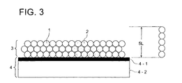
- the printing plate material before being heated comprises a hydrophilic support 4 and provided thereon, an image formation layer 3 containing thermoplastic resin particles 1, wherein the adhesion force (fb) between the hydrophilic support 4 and the thermoplastic resin particles 1 and the adhesion force (fp) between the thermoplastic resin particles preferably satisfy the following relationship: fb > fp
- the planographic printing plate material after imagewise heating comprises a hydrophilic support 4 and provided thereon, an image formation layer 3 containing unheated thermoplastic resin particles 1 and heated thermoplastic resin particles 2, and the adhesion force (fb) and the adhesion force (fb') between the hydrophilic support 4 and the thermoplastic resin particles 2 satisfy the following relationship: fb ⁇ > fb
- polyester resin As material for the thermoplastic resin particles, polyester resin is used in view of printing durability and on-press developability.
- the polyester resin preferably has a weight average molecular weight of preferably from 5,000 to 30,000.
- Examples of the polyester resin particles include Vilonal MD-1200, Vilonal PMD-1200 and Vilonal PMD-1100 each available from Toyo Boseki Co., Ltd.
- the image formation layer can be adhered at a certain strength to the hydrophilic support surface or the hydrophilic layer, and can be easily removed therefrom during on-press development.
- the resins described above have a glass transition point (Tg) of preferably not less than 40 °C, and more preferably from 40 to 150 °C, and most preferably from 50 to 120 °C.
- Tg glass transition point
- a glass transition point (Tg) less than 40 °C may result in staining or in lowering of on-press developability after storage.
- the rupture elongation of the thermoplastic polyester particles is preferably less than 100%, and more preferably not more than 20%.
- the rupture elongation of the thermoplastic polyester particles is measured according to ISO 527.
- the minimum film formation temperature of the thermoplastic resin particles is preferably not less than 80 °C.
- the minimum film formation temperature can be controlled by the content in the dispersion solvent of organic solvents other than water which swell or dissolve the thermoplastic resin particles.
- the organic solvent content of the dispersion solvent is not more than 15%, and preferably not more than 10% by weight.
- the minimum film formation temperature of the thermoplastic resin particles in the image formation layer is determined according to a method described in ISO 2115.
- the average particle size of the thermoplastic resin particles is preferably from 0.01 to 2 ⁇ m, and more preferably from 0.1 to 1 ⁇ m.
- the thermoplastic resin particle content of the image formation layer is from 60 to 100% by weight, preferably from 80 to 100% by weight, and more preferably from 90 to 100% by weight.
- the image formation layer containing thermoplastic resin particles in the particle form can be formed by coating a support with a thermoplastic resin particle-containing image formation layer coating solution and drying the coated layer at a temperature lower than a Tg of the thermoplastic resin particles. Further, such an image formation layer can be also formed by employing a thermoplastic resin particle-containing image formation layer coating solution in which the thermoplastic resin particles are dispersed in a dispersion solvent in which an organic solvent softening or dissolving the thermoplastic resin particles is reduced or eliminated, whereby the lowest film formation temperature is elevated.
- the drying temperature may be low but is preferably at least 10 °C.
- a printing plate material even though it partially comprises a continuous phase image formation layer in which thermoplastic resin particles are fused to form a continuous phase, increases the number of prints to be printed until a sufficient ink density is obtained at on-press development (at printing), resulting in increase of paper waste. Further, boundaries between image and non-image portions are not sharp, resulting in lowering of dot reproduction.
- thermoplastic resin particles in the form of particles (thermoplastic resin particles)
- the following formula shall be satisfied: L ⁇ d ⁇ 5 ⁇ L
- L represents an average particle size of the thermoplastic resin particles in the particle form
- d represents the thickness of the image formation layer.
- the thickness d of the image formation layer containing the thermoplastic resin particles with an average particle size of L is substantially not less than L.
- the hydrophilic support surface is sufficiently covered with the thermoplastic resin particles. The sufficient coverage provides high ink receptivity at image portions.
- d ⁇ 5L the proportion of the thermoplastic resin particles in the image formation layer contacting the hydrophilic support increases. It is important to increase adhesion of the thermoplastic resin particles in the image formation layer to the hydrophilic support by heating in order to obtain high printing durability.
- the relationship d ⁇ 5L is advantageous in the following points:
- Figs. 2 or 3 represents another embodiment of the printing plate material of the invention.
- the printing plate material after imagewise heating comprises a hydrophilic support 4 with a hydrophilic layer 4-1 provided on a support 4-2, and an image formation layer 3 containing unheated thermoplastic resin particles 1 and heated thermoplastic resin particles 2, wherein the thickness of the image formation layer is more than 5L, L representing an average particle size of the thermoplastic resin particles.
- the printing plate material after imagewise heating comprises a hydrophilic support 4 with a hydrophilic layer 4-1 provided on a support 4-2, and an image formation layer 3 containing unheated thermoplastic resin particles 1 and heated thermoplastic resin particles 2, wherein the thickness of the image formation layer is more than 5L, L representing an average particle size of the thermoplastic resin particles.
- the printing plate material after imagewise heating comprises a hydrophilic support 4 with a hydrophilic layer 4-1 provided on a support 4-2, and an image formation layer 3 containing unheated thermoplastic resin particles 1 and heated thermoplastic resin particles 2, wherein the thickness of the image formation layer is less than 5L, L representing an average particle size of the thermoplastic resin particles.
- a hydrophilic layer containing a light-to-heat conversion material is provided on a hydrophilic support, and an image formation layer, containing thermoplastic resin particles piled up in a stone wall form, is provided on the hydrophilic layer.
- an image formation layer containing thermoplastic resin particles piled up in a stone wall form.
- the image formation layer in the invention can further contain the following substances.
- the image formation layer preferably contains the light-to-heat conversion materials described above, water soluble resins or water dispersible resins.
- the image formation layer contains the light-to-heat conversion materials in an amount of not more than 10% by weight.
- the water soluble resins or water dispersible resins include oligosaccharides, polysaccharides, polyethylene oxide, polypropylene oxide, polyvinyl alcohol, polyethylene glycol (PEG), polyvinyl ether, a styrene-butadiene copolymer, a conjugation diene polymer latex of methyl methacrylate-butadiene copolymer, an acryl polymer latex, a vinyl polymer latex, polyacrylic acid, polyacrylic acid salts, polyacrylamide, and polyvinyl pyrrolidone.
- oligosaccharides polysaccharides, polyacrylic acid, polyacrylic acid salts (sodium salt, etc.), and polyacrylamide are preferred.
- oligosaccharides examples include raffinose, trehalose, maltose, galactose, sucrose, and lactose. Among these, trehalose is preferred.
- polysaccharides examples include starches, celluloses, polyuronic acid and pullulan.
- cellulose derivatives such as a methyl cellulose salt, a carboxymethyl cellulose salt and a hydroxyethyl cellulose salt are preferred, and a sodium or ammonium salt of carboxymethyl cellulose is more preferred.
- the molecular weight of polyacrylic acid, polyacrylic acid salts (sodium salt, etc.), and polyacrylamide has a molecular weight of preferably from 3,000 to 5,000,000, and more preferably from 5,000 to 1,000,000.
- the water soluble resins or water dispersible resins may be added to the image formation layer in order to improve an anti-stain property after storage, heat resistance or on-press-developability. However, they may lower strength of the image formation layer at image portions, and are preferably added to the image formation layer in the possible lowest amount.
- the addition amount of the water soluble resins or water dispersible resins in the image formation layer is preferably not more than 30% by weight, more preferably not more than 20% by weight, and most preferably from 1 to 20% by weight.
- the addition amount thereof in the image formation layer may be zero percent by weight.
- thermoplastic resin particles in the particle form improve an anti-stain property after storage or heat resistance, and can reduce the addition amount of the water soluble resins or water dispersible resins.
- a water-soluble surfactant may be contained in the image formation layer in the invention.
- a silicon atom-containing surfactant and a fluorine atom-containing surfactant can be used.
- the image formation layer in the invention can contain an acid (phosphoric acid or acetic acid) or an alkali (sodium hydroxide, silicate, or phosphate) to adjust pH.
- the coating amount of the image formation layer is from 0.01 to 10 g/m 2 , preferably from 0.1 to 3 g/m 2 , and more preferably from 0.2 to 2 g/m 2 .
- a protective layer can be provided on the image formation layer.
- the water soluble resins or the water dispersible resins described above can be preferably used.
- the protective layer in the invention may be the hydrophilic overcoat layer disclosed in Japanese Patent O.P.I. Publication Nos. 2002-19318 and 2002-86948 .
- the coating amount of the protective layer is from 0.01 to 10 g/m 2 , preferably from 0.1 to 3 g/m 2 , and more preferably from 0.2 to 2 g/m 2 .
- On-press development is carried out by supplying printing ink or a dampening solution to the (exposed) planographic printing plate material.
- the dampening solution used for printing is generally acidic. Exposure by infrared laser can be carried out on a printing press.
- the image formation layer forms image portions at exposed portions and forms oleophilic non-image portions at unexpected portions where the image formation layer at non-image portions is removed. Removal of the image formation layer at non-image portions can be carried out employing water, and can be carried out employing printing ink or a dampening solution on a printing press (subjected to so-called on-press development).
- Removal on a press of the image formation layer at non-image portions (unexposed portions) of a printing plate material, which is mounted on the plate cylinder, can be carried out by bringing a dampening roller and an inking roller into contact with the image formation layer while rotating the plate cylinder, and can be also carried out according to various sequences such as those described below or another appropriate sequence.
- the supplied amount of dampening solution may be adjusted to be greater or smaller than the amount ordinarily supplied in printing, and the adjustment may be carried out stepwise or continuously.
- a 0.24 mm thick aluminum plate (material 1050, refining H16) was immersed in an aqueous 1% by weight sodium hydroxide solution at 50 °C to give an aluminum dissolution amount of 2 g/m 2 , washed with water, immersed in an aqueous 0.1% by weight hydrochloric acid solution at 25 °C for 30 seconds to neutralize, and then washed with water.
- the aluminum plate was subjected to an electrolytic surface-roughening treatment in an electrolytic solution containing 10 g/liter of hydrochloric acid and 0.5 g/liter of aluminum at a peak current density of 50 A/dm 2 employing an alternating current with a sine waveform, in which the distance between the plate surface and the electrode was 10 mm.
- the electrolytic surface-roughening treatment was divided into 12 treatments, in which the quantity of electricity used in one treatment (at a positive polarity) was 40 C/dm 2 , and the total quantity of electricity used (at a positive polarity) was 480 C/dm 2 . Standby time of 5 seconds, during which no surface-roughening treatment was carried out, was provided after each of the separate electrolytic surface-roughening treatments.
- the resulting aluminum plate was immersed in an aqueous 1% by weight sodium hydroxide solution at 50 °C and etched to give an aluminum etching amount (including smut produced on the surface) of 1.2 g/m 2 , washed with water, neutralized in an aqueous 10% by weight sulfuric acid solution at 25 °C for 10 seconds, and washed with water.
- the aluminum plate was subjected to anodizing treatment in an aqueous 20% by weight sulfuric acid solution at a constant voltage of 20 V, in which a quantity of electricity of 150 C/dm 2 was supplied, and washed with water.
- the washed surface of the plate was squeegeed, and the plate was immersed in an aqueous 1% by weight disodium hydrogen phosphate solution at 70 °C for 30 seconds, washed with water, and dried at 80 °C for 5 minutes. Thus, a surface roughened support 1 was obtained.
- the surface roughened support 1 had a surface roughness Ra of 460 nm.
- the resulting coating solution 1 was coated on the surface roughened support 1 employing a wire bar, and dried at 100 °C for 3 minutes to give a hydrophilic layer having a dry thickness of 1.5 g/m 2 . Subsequently, the resulting material was then subjected to aging at 60 °C for 24 hours. Thus, a support 1 with a hydrophilic layer (hereinafter also referred to as a hydrophilic support 1) was obtained.
- Table 1 Composition of hydrophilic layer coating solution 1
- Cu-Fe-Mn type metal oxide black pigment TM-3550 black aqueous dispersion ⁇ prepared by dispersing TM-3550 black powder having a particle size of 0.1 ⁇ m produced by Dainichi Seika Kogyo Co., Ltd.
- Table 2 Composition of image formation layer coating solution 1
- Water-dispersion copolyester resin emulsion Vylonal ® PMD-1200 (Tg: 67 °C, rupture elongation: 5%, a solid content of 41% by weight, produced by Toyo Boseki Co., Ltd.) 22.4 parts by weight
- Planographic printing plate material samples 2 through 8 were prepared in the same manner as in printing plate material sample 1, except that the thermoplastic resin particle emulsion as shown in Table 3 was used and the drying temperature was changed to that as shown in Table 3.
- the content ratio of the thermoplastic resin to the water soluble resin, and the coating amount of the thermoplastic resin and the water soluble resin were the same as printing plate material sample 1.
- Each of the resulting printing plate samples was wound around an exposure drum and imagewise exposed. Exposure was carried out employing an infrared laser (having a wavelength of 830 nm and a beam spot diameter of 18 ⁇ m) at a resolution of 2400 dpi and at a screen line number of 175 to form a solid image, and a dot image with a dot area of 1 to 99%. In the exposure, the exposure energy was 300 mJ/cm 2 . The term, "dpi" shows the number of dots per 2.54 cm.
- the exposed printing plate material was mounted on a plate cylinder of a printing press and then printing was carried out in the same printing sequence as a conventional PS plate.
- Printing was carried out employing a printing press, DAIYA 1F-1 produced by Mitsubishi Jukogyo Co., Ltd., and employing coated paper sheets, a dampening solution, a 2% by weight solution of Astromark 3 (produced by Nikken Kagaku Kenkyusyo Co., Ltd.), and printing ink (TK Hyunity Magenta, produced by Toyo Ink Manufacturing Co.).
- the smallest number of paper sheets printed from when printing started until when on-press development was completed was counted and evaluated as a measure of on-press developability.
- Time when prints having no stain at non-image portions, an ink density of 1.6 or more at solid images, and reproduced 95% dot area were obtained was regarded as the completion point of the on-press development.
- the ink density was determined at M mode employing a densitometer Macbeth RD 918.
- Printing was carried out for 20,000 copies. Stains at non-image portions were observed in the 100 th copy, 5,000 th copy, 10,000 th copy, 15,000 th copy and 20,000 th copy, and were evaluated according to the following criteria:
- Dot quality was evaluated according to the following criteria:
- Printing was carried out for 20,000 copies. The number of prints printed from when printing started till when dots in the image with a 3% dot area began disappearing was counted, and evaluated as a measure of printing durability.
- Table 4 Sample No. On-press developability (number) Anti-stain property at non-image portions (number) Dot quality at image portions Resistance to blanket contamination Printing durability 100th 5,000th 10,000th 15,000th 20,000th 1 100 or more C C C C C C C C C - 2 40 B C C C C C B - 3 10 A A A A A A A 20,000 or more 4 100 or more C C C C C C A - 5 15 A A A A A A A 20,000 6 15 A A A A A A A A 14,000 7 15 A A A A A A A A 16,000 8 20 A A A A B B A 16, 000
- "-" shows that since on-press development was impossible or stain markedly occurred at the non-image portions, no evaluation was made.
- samples 3, and 5 through 8 provide excellent results in on-press developability, the anti-stain property at the non-image portions, dot quality, resistance to blanket contamination and printing durability, compared with samples 1, 2 and 4. This is considered to result from increase of adhesion of the image formation to the support.
- the support 1 obtained above was immersed in an aqueous 0.1% by weight ammonium acetate (produced by Kanto Kagaku Co., Ltd.) solution at 80 °C for 30 seconds with stirring, washed with water, dried, then immersed in an aqueous 0.1% by weight carboxymethylcellulose 1150 (produced by Daicel Kagaku Co., Ltd.) solution at 80 °C for 30 seconds with stirring, washed with water, and dried.
- a support with a hydrophilic layer (a hydrophilic support 2) was obtained.
- Printing plate material samples 9 through 15 were prepared in the same manner as in planographic printing plate material sample 3, except that the following image formation layer coating solution (2) composition as shown in Table 5 was coated on the hydrophilic support 2 and dried to form an image formation layer having each component content as shown in Table 6 of the composition. In the above, drying temperature was 50 °C.
- Table 7 Composition of image formation layer coating solution 2
- Water-dispersion copolyester resin emulsion Vylonal ® MD-1200 (Tg: 67 °C, rupture elongation: 5%, a solid content of 34% by weight, produced by Toyo Boseki Co., Ltd.)
- Aqueous solution of sodium polyacrylate AQUALIC ® DL522 (solid content 10%, produced by Nippon Shokubai Co., Ltd.)
- Light-to-heat conversion material an aqueous 1% by weight aqueous solution of ADS830WS (produced by American Dye Source Co., Ltd.) Pure water
- Table 6 Materials Concentration Sample No.
- the samples provide excellent results in on-press developability, the anti-stain property at the non-image portions, resistance to blanket contamination and printing durability, even when the water soluble resin content is small.
- Printing plate material samples 16 through 23 were prepared in the same manner as in printing plate material sample. 3 of Example 1, except that the image formation layer thickness was changed to those as shown in Table 8. The resulting samples were evaluated in the same manner as in Example 1. The results are shown in Table 8. The thickness of the image formation layer was measured from a section of the samples employing an electron microscope. The average particle size L of Vylonal ® PMD-1200 used as thermoplastic resin particles was 0.15 ⁇ m. Table 8 Sample No.
- inventive samples 16 through 21 which satisfy the relationship L ⁇ d ⁇ 5L, provide excellent printing properties.
Landscapes
- Physics & Mathematics (AREA)
- Optics & Photonics (AREA)
- Thermal Sciences (AREA)
- Engineering & Computer Science (AREA)
- Manufacturing & Machinery (AREA)
- Printing Plates And Materials Therefor (AREA)
- Materials For Photolithography (AREA)
- Photosensitive Polymer And Photoresist Processing (AREA)
- Manufacture Or Reproduction Of Printing Formes (AREA)
Description
- The present invention relates to a printing plate material, and particularly to a printing plate material capable of forming an image according to a computer to plate (CTP) system.
- The printing plate material for CTP, which is inexpensive, can be easily handled, and has a printing ability comparable with that of a PS plate, is required accompanied with the digitization of printing data. Recently, a thermal processless printing plate material which can be applied to a printing press employing a direct imaging (DI) process without development by a special developing agent or a versatile thermal processless printing plate material which can be treated in the same manner as in PS plates has been required.
- As a thermal processless printing plate material, there is Thermo-Lite produced by Agfa Co., Ltd. In a thermal processless printing plate material, an image is formed according to a recording method employing a thermal laser emitting light with infrared to near infrared wavelengths. The thermal processless type printing plate material employing this recording method is divided into an ablation type printing plate material, a development-on-press type heat fusible image formation layer-containing printing plate material, and a phase change type printing plate material.
- Examples of the ablation type printing plate material include those disclosed in for example, Japanese Patent O.P.I. Publication Nos.
8-507727 6-186750 6-199064 7-314934 10-58636 10-244773 - Examples of the development-on-press type heat fusible image formation layer-containing printing plate material include printing plate materials disclosed in for example,
Japanese Patent Publication Nos. 2938397 2938398 - Examples of the phase change type printing plate material include those disclosed in for example,
Japanese Patent O.P.I. Publication No. 11-240270 - A planographic printing plate material employing heat melting particles with a melting point of from 40 to 150 °C having specific physical properties is disclosed (see for example,
Japanese Patent O.P.I. Publication No. 2001-200059 - Lithographic printing plate precursors are described in
EP A 1 145 848 - A method for the preparation of negative-working heat-sensitive lithographic printing plate precursors is described in
EP A 1 243 410 . The method comprises the steps of preparing an aqueous dispersion comprising particles of a hydrophobic polymer A which is not soluble or swellable in an aqueous alkaline developer and particles of a further polymer B which is soluble or swellable in an aqueous alkaline developer but not soluble or swellable in water, applying in a second step the aqueous dispersion on a lithographic substrate which possesses a hydrophilic surface and finally heating the image-recording layer at a temperature which is higher than the softening temperature of the polymer B. - A further method for making lithographic printing plates is described in
EP A 1 092 555 - An object of the invention is to provide a printing plate material, capable of being subjected to on-press development on a printing press, which provides excellent dot reproduction and improved print quality, and minimizes "ghost" resulting from stains of a blanket of a printing press, stains resulting from printing ink or dampening solution, and waste paper sheets at an initial stage of printing.
-
- Fig. 1(a) is a sectional view of a printing plate material of the invention before heated,
- Fig. 1(b) is a sectional view of a printing plate material of the invention after imagewise heated,
- Fig. 2 is a sectional view of one embodiment of the printing plate material of the invention, and
- Fig. 3 shows a sectional view of another embodiment of the planographic printing plate material of the invention.
- The above object of the invention can be attained by the following constitutions:
- 1-1. A printing plate material comprising a hydrophilic support and provided thereon, an image forming layer containing thermoplastic resin particles in an amount of from 60 to 100% by weight, the thermoplastic resin particles being thermoplastic polyester particles having a glass transition point (Tg) and an average particle size of from 0.01 to 2 µm, wherein the following relation is satisfied, L ≤ d ≤ 5L, wherein d represents the thickness of the image formation layer and L represents the average particle size of the thermoplastic resin particles.
- 1-2. The printing plate material of
item 1 above, wherein the content of the thermoplastic resin particles in the image formation layer is from 80 to 100% by weight. - 1-3. The printing plate material of item 1-1 or 1-2 above, wherein the glass transition point (Tg) of the thermoplastic resin particles is not less than 40 °C.
- 1-4. The printing plate material of any of items 1-1 to 1-3 above, wherein the image formation layer contains a water soluble resin or a water dispersible resin in an amount of not more than 20% by weight.
- 1-5. The printing plate material of item 1-4 above, wherein the water soluble resin or the water dispersible resin is selected from the group consisting of oligosaccharides, polysaccharides, polyacrylic acid, polyacrylic acid salts, and polyacrylamide.
- 1-6. The printing plate material of any of items 1-1 to 1-5 above, wherein the image formation layer contains a light-to-heat conversion material in an amount of not more than 10% by weight.
- 1-7. The printing plate material of any of items 1-1 to 1-6 above, wherein the image formation layer contains a light-to-heat conversion material in an amount of not more than 10% by weight, and a water soluble resin or a water dispersible resin in an amount of not more than 20% by weight.
- 1-8. The printing plate material of any of items 1-1 to 1-7 above, wherein the polyester has a weight average molecular weight of 5,000 to 30,000.
- 1-9. A process of manufacturing a printing plate material comprising a hydrophilic support and provided thereon, an image formation layer containing thermoplastic resin particles in an amount of from 60 to 100% by weight,
- The present invention will be detailed below.
- The printing plate material of the invention comprises a hydrophilic support and provided thereon, an image formation layer containing thermoplastic resin particles in an amount of from 60 to 100% by weight, the thermoplastic resin particles having a glass transition point (Tg) and an average particle size of from 0.01 to 2 µm.
- In the invention, the particle size of particles refers to a diameter of a circle having the same area as the projected image of the particles in an SEM photograph of the particles, and the average particle size of particles refers to the average of the particle size of arbitrarily selected 50 particles in the SEM photograph. Herein, the SEM photograph of the particles was taken by means of a scanning electron microscope S-800 (produced by Hitachi Seisakusho Co., Ltd.) at a magnification of 50,000.
- As the support in the invention, those well known in the art as supports for printing plates can be used. Examples of the support include a metal plate, a plastic film sheet, a paper sheet treated with polyolefin, and composite materials such as laminates thereof. The thickness of the support is not specifically limited as long as a printing plate having the support can be mounted on a printing press, and is advantageously from 50 to 500 µm in easily handling.
- Examples of the metal plate include iron, stainless steel, and aluminum. Aluminum is especially preferable in its gravity and stiffness. Aluminum is ordinarily used after degreasing with an alkali, an acid or a solvent to remove oil on the surface, which has been used when rolled and wound around a spool. The degreasing is carried out preferably employing an aqueous alkali solution. In order to increase adhesion between the support and a coating layer, it is preferred that the surface of the support is subjected to adhesion increasing treatment or is coated with a subbing layer. For example, the support is immersed in a solution containing silicate or a coupling agent such as a silane coupling agent, or the support is coated with the solution and then sufficiently dried. Anodization treatment is considered to be one kind of adhesion increasing treatment, and can be used. The anodization treatment and the immersing or coating treatment described above can be used in combination. Aluminum plate (so-called grained aluminum plate), which has been surface-roughened with a conventional method, can be used as a support having a hydrophilic surface.
- The aluminum plate used in the printing plate material in the invention is an aluminum plate or an aluminum alloy plate. As the aluminum alloy, there can be used various ones including an alloy of aluminum and a metal such as silicon, copper, manganese, magnesium, chromium, zinc, lead, bismuth, nickel, titanium, sodium or iron.
- It is preferable that the aluminum plate is subjected to degreasing treatment for removing rolling oil prior to surface roughening. The degreasing treatments include degreasing treatment employing solvents such as trichlene and thinner, and an emulsion degreasing treatment employing an emulsion such as kerosene or triethanol. It is also possible to use an aqueous alkali solution such as an aqueous solution of sodium hydroxide, potassium hydroxide, sodium carbonate, or sodium phosphate for the degreasing treatment. When such an aqueous alkali solution is used for the degreasing treatment, it is possible to remove soils and an oxidized film which can not be removed by the above-mentioned degreasing treatment alone. When the aqueous alkali solution is used for the degreasing treatment, the resulting plate is preferably subjected to neutralization treatment in an aqueous solution of an acid such as phosphoric acid, nitric acid, sulfuric acid, chromic acid, or in an aqueous solution of a mixture thereof. The electrolytic surface roughening after the neutralization is carried out preferably in the same acid solution as in the neutralization treatment.
- The electrolytic surface roughening treatment of the aluminum plate is carried out according to a known method, but prior to that, chemical surface roughening treatment and/or mechanical surface roughening treatment may be carried out. The mechanical surface roughening treatment is preferably carried out.
- The chemical surface roughening treatment is carried out employing an aqueous alkali solution such as an aqueous solution of sodium hydroxide, potassium hydroxide, sodium carbonate, or sodium phosphate in the same manner as in degreasing treatment above. After that, the resulting plate is preferably subjected to neutralization treatment in an aqueous solution of an acid such as phosphoric acid, nitric acid, sulfuric acid, chromic acid, or in an aqueous solution of a mixture thereof. The electrolytic surface roughening after the neutralization is carried out preferably in the same acid solution as the neutralization treatment.
- Though there is no restriction for the mechanical surface roughening method, a brushing roughening method and a honing roughening method are preferable. The brushing roughening method is carried out by rubbing the surface of the plate with a cylindrical brush with a brush hair with a diameter of 0.2 to 1 mm, while supplying slurry, in which an abrasive is dispersed in water, to the surface of the plate. The honing roughening method is carried out by ejecting obliquely slurry, in which an abrasive is dispersed in water, with pressure applied from nozzles to the surface of the plate. Examples of the abrasive include those generally used as abrasives such as volcanic ashes, alumina, or silicon carbide. The particle size of the abrasive is #200 to #3000, preferably #400 to #2000, and more preferably #600 to #1000.
- After the plate has been roughened mechanically, it is preferably dipped in an acid or an aqueous alkali solution in order to remove abrasives and aluminum dust, etc. which have been embedded in the surface of the support or to control the shape of pits formed on the plate surface, whereby the surface is etched. Examples of the acid include sulfuric acid, persulfuric acid, hydrofluoric acid, phosphoric acid, nitric acid and hydrochloric acid, and examples of the alkali include sodium hydroxide and potassium hydroxide.
- In the invention, the aluminum plate was mechanically surface roughened with an abrasive with a particle size of not less than #400, followed by etching treatment employing an aqueous alkali solution, whereby a complex surface structure formed due to the mechanical surface roughening treatment can be changed to a surface having a smooth convexoconcave structure. The resulting aluminum plate has a waviness of a relatively long wavelength of several microns to scores microns. The resulting aluminum plate further being subjected to electrolytic surface roughening treatment described later, an aluminum support is obtained which provides a good printing performance and good printing durability. Further, the aluminum plate can reduce the quantity of electricity during the electrolytic surface roughening treatment, contributing to cost reduction.
- The resulting plate after being dipped in the aqueous alkali solution is preferably subjected to neutralization treatment in an aqueous solution of an acid such as phosphoric acid, nitric acid, sulfuric acid, chromic acid, or in an aqueous solution of a mixture thereof. The electrolytic surface roughening after the neutralization is preferably carried out in the same acid solution as the neutralization treatment.
- The electrolytic surface roughening treatment in the invention is carried out in an acidic electrolytic solution employing an alternating current. As the acidic electrolytic solution, an acidic electrolytic solution used in a conventional electrolytic surface roughening treatment can be used, but a hydrochloric acid or nitric acid electrolytic solution is preferably used. In the invention, a hydrochloric acid electrolytic solution is especially preferably used. As a current waveform used in the electrolytic surface roughening treatment, various waveforms such as a rectangular wave, trapezoidal wave, sawtooth wave or sine wave can be used, but sine wave is preferably used. Separated electrolytic surface roughening treatments disclosed in
Japanese Patent O.P.I. Publication No. 10-869 - In the electrolytic surface roughening treatment carried out using an electrolytic solution of nitric acid, voltage applied is preferably from 1 to 50 V, and more preferably from 5 to 30 V. The current density (in terms of peak value) used is preferably from 10 to 200 A/dm2, and more preferably from 20 to 150 A/dm2. The total quantity of electricity is preferably 100 to 2000 C/dm2, more preferably 200 to 1500 C/dm2, and most preferably 200 to 1000 C/dm2. Temperature during the electrolytic surface roughening treatment is preferably from 10 to 50° C, and more preferably from 15 to 45°C. The nitric acid concentration in the electrolytic solution is preferably from 0.1 % by weight to 5 % by weight. It is possible to optionally add, to the electrolytic solution, nitrates, chlorides, amines, aldehydes, phosphoric acid, chromic acid, boric acid, acetic acid or oxalic acid.
- In the electrolytic surface roughening treatment carried out using an electrolytic solution of hydrochloric acid, voltage applied is preferably from 1 to 50 V, and more preferably from 5 to 30 V. The current density (in terms of peak value) used is preferably from 10 to 200 A/dm2, and more preferably from 20 to 150 A/dm2. The total quantity of electricity is preferably 100 to 2000 C/dm2, and more preferably 200 to 1000 C/dm2. Temperature during the electrolytic surface roughening treatment is preferably from 10 to 50° C, and more preferably from 15 to 45°C. The hydrochloric acid concentration in the electrolytic solution is preferably from 0.1 % by weight to 5 % by weight. It is possible to optionally add, to the electrolytic solution, nitrates, chlorides, amines, aldehydes, phosphoric acid, chromic acid, boric acid, acetic acid or oxalic acid.
- In the invention, the electrolytically surface roughened plate is dipped and subjected to etching treatment in an aqueous alkali solution in order to remove aluminum dust produced on the plate surface, or to control the shape of pits formed on the plate surface, whereby the surface is etched. Examples of the alkali solution include a solution of sodium hydroxide, potassium hydroxide, sodium carbonate or sodium phosphate. This etching treatment improves initial printability and anti-stain property of a printing plate material comprising an image formation layer.
- Etching treatment after electrolytically surface roughening can be carried out employing a solution of an acid such as a sulfuric acid, persulfuric acid, hydrofluoric acid, phosphoric acid, nitric acid, or hydrochloric acid. Etching treatment employing an acid solution is likely to lower initial printability or anti-stain property of a printing plate material.
- The reason is not clear. This is probably because etching treatment due to alkalis provides a fine surface structure of the electrolytically surface roughened plate different from etching treatment due to acids. Etching treatment due to alkalis, if etching amount is small, easily dissolves aluminum of the plate surface to give a surface having a smooth convexoconcave structure as described above, whereby a component in the image formation layer from which stains result, e.g., a light-to-heat conversion material to be described later or a visualizing agent is easily removed during on-press development.
- When the surface of the electrolytically surface roughened aluminum plate is etched in the aqueous alkali solution, the etching amount of the aluminum plate is preferably from 0.05 to 2.0 g/m2. The etching amount less than 0.05 g/m2 has the problem in that smuts produced on the plate surface are not completely removed, and the etching amount exceeding 2.0 g/m2 has the problem in that pits formed during the electrolytic surface roughening treatment have been excessively dissolved, lowering printing durability.
- The resulting plate after being dipped in the aqueous alkali solution in the above is preferably subjected to neutralization treatment in an aqueous solution of an acid such as phosphoric acid, nitric acid, sulfuric acid, chromic acid, or in an aqueous solution of a mixture thereof. The anodization treatment after the neutralization treatment is carried out preferably in the same acid solution as in the neutralization treatment.
- After the aluminum plate has been subjected to each of the surface treatments described above, it is subjected to anodization treatment. There is no restriction in particular for the method of anodization treatment used in the invention, and known methods can be used. The anodization treatment forms an anodization film on the surface of the aluminum plate. For the anodization treatment in the invention there is preferably used a method of carrying out electrolysis by applying a current density of from 1 to 10 A/dm2 to an aqueous solution containing sulfuric acid and/or phosphoric acid in a concentration of from 10 to 50%, as an electrolytic solution. However, it is also possible to use a method of carrying out electrolysis by applying a high current density to sulfuric acid as described in
U.S. Patent No. 1,412,768 , or a method of carrying out electrolysis in phosphoric acid as described inU.S. Patent No. 3,511,661 . - The aluminum plate, which has been subjected to anodization treatment, is optionally subjected to sealing treatment. For the sealing treatment, it is possible to use known sealing treatment carried out using hot water, boiling water, steam, an aqueous dichromate solution, a nitrite solution and an ammonium acetate solution. The aluminum plate subjected to anodization treatment may be subjected to surface treatment other than the sealing treatment. Examples of the surface treatment include known treatments such as silicate treatment, phosphate treatment, various organic acid treatment, PVPA treatment and boehmite treatment. Further, the aluminum plate subjected to anodization treatment may be subjected to surface treatment disclosed in
Japanese Patent O.P.I. Publication No. 8-314157 - Examples of the plastic film include a polyethylene terephthalate film, a polyethylene naphthalate film, a polyimide film, a polyamide film, a polycarbonate film, a polysulfone film, a polyphenylene oxide film, and a cellulose ester film.
- A support with a backcoat layer on the side (rear surface) opposite the image formation layer can be preferably used in order to control slippage of a rear surface (for example, to decrease the friction of the rear surface to the plate cylinder of a printing press).
- In the printing plate material of the invention, a hydrophilic layer is preferably provided on the support to contact an image formation layer described later. Material used in the hydrophilic layer is preferably a metal oxide. The metal oxide is preferably metal oxide particles. Examples of the metal oxide particles include colloidal silica particles, an alumina sol, a titania sol and another metal oxide sol. The metal oxide particles may have any shape such as spherical, needle-like, and feather-like shape. The average particle size is preferably from 3 to 100 nm, and plural kinds of metal oxide each having a different size may be used in combination. The surface of the particles may be subjected to surface treatment. The metal oxide particles can be used as a binder, utilizing its layer forming ability. The metal oxide particles are suitably used in a hydrophilic layer since they minimize lowering of the hydrophilicity of the layer as compared with an organic compound binder.
- Among the above-mentioned, colloidal silica is particularly preferred. The colloidal silica has a high layer forming ability under a drying condition with a relatively low temperature, and can provide a good layer strength.
- It is preferred that the colloidal silica used in the invention is necklace-shaped colloidal silica or colloidal silica particles having an average particle size of not more than 20 nm, each being described later. Further, it is preferred that the colloidal silica provides an alkaline colloidal silica solution as a colloid solution.
- The necklace-shaped colloidal silica to be used in the invention is a generic term of an aqueous dispersion system of spherical silica having a primary particle size of the order of nm. The necklace-shaped colloidal silica to be used in the invention means a "pearl necklace-shaped" colloidal silica formed by connecting spherical colloidal silica particles each having a primary particle size of from 10 to 50 µm so as to attain a length of from 50 to 400 nm. The term of "pearl necklace-shaped" means that the image of connected colloidal silica particles is like to the shape of a pearl necklace. The bonding between the silica particles forming the necklace-shaped colloidal silica is considered to be -Si-O-Si-, which is formed by dehydration of -SiOH groups located on the surface of the silica particles. Concrete examples of the necklace-shaped colloidal silica include Snowtex-PS series produced by Nissan Kagaku Kogyo, Co., Ltd.
- The hydrophilic layer of the printing plate material of the invention preferably contains porous metal oxide particles as metal oxides. Examples of the porous metal oxide particles include porous silica particles, porous aluminosilicate particles or zeolite particles as described later.
- The porous silica particles are ordinarily produced by a wet method or a dry method. By the wet method, the porous silica particles can be obtained by drying and pulverizing a gel prepared by neutralizing an aqueous silicate solution, or pulverizing the precipitate formed by neutralization. By the dry method, the porous silica particles are prepared by combustion of silicon tetrachloride together with hydrogen and oxygen to precipitate silica. The porosity and the particle size of such particles can be controlled by variation of the production conditions. The porous silica particles prepared from the gel by the wet method is particularly preferred.
- The porous aluminosilicate particles can be prepared by the method described in, for example,
JP O.P.I. No. 10-71764 - The porosity of the particles is preferably not less than 1.0 ml/g, more preferably not less than 1.2 ml/g, and most preferably of from 1.8 to 2.5 ml/g, in terms of pore volume before the dispersion.
- The pore volume is closely related to water retention of the coated layer. As the pore volume increases, the water retention is increased, stain is difficult to occur, and water tolerance is high. Particles having a pore volume of more than 2.5 ml/g are brittle, resulting in lowering of durability of the layer containing them. Particles having a pore volume of less than 1.0 ml/g results in lowering of anti-stain property or water tolerance in printing. The particle size of the particles dispersed in the hydrophilic layer (or in the dispersed state before formed as a layer) is preferably not more than 1 µm, and more preferably not more than 0.5 µm. Presence in the hydrophilic layer of particles with an extremely large size forms porous and sharp protrusions on the hydrophilic layer surface, and ink is likely to remain around the protrusions, which may produce stain at non-image portions of the printing plate and on the blanket of a press during printing.
- Zeolite is a crystalline aluminosilicate, which is a porous material having voids of a regular three dimensional net work structure and having a pore size of 0.3 to 1 nm. Natural and synthetic zeolites are expressed by the following formula.
(M1, (M2)1/2)m(AlmSinO2(m+n)) · xH2O
- In the above, M1 and M2 are each exchangeable cations. Examples of M1 include Li+, Na+, K+, T1+, Me4N+ (TMA), Et4N+ (TEA), Pr4N+ (TPA), C7H15N2+, and C8H16N+, and examples of M2 include Ca2+, Mg2+, Ba2+, Sr2+ and (C8H18N)2 2+. Relation of n and m is n ≥ m, and consequently, the ratio of m/n, or that of Al/Si is not more than 1. A higher Al/Si ratio shows a higher content of the exchangeable cation, and a higher polarity, resulting in higher hydrophilicity. The Al/Si ratio is within the range of preferably from 0.4 to 1.0, and more preferably 0.8 to 1.0. "x" is an integer.
- The particle size of the porous inorganic particles in the hydrophilic layer is preferably not more than 1 µm, and more preferably not more than 0.5 µm.
- An aqueous solution of a silicate is also usable as another additive to the hydrophilic layer in the invention. An alkali metal silicate such as sodium silicate, potassium silicate or lithium silicate is preferable, and the SiO2/M2O (M represents an alkali metal) is preferably selected so that the pH value of the coating liquid after addition of the silicate exceeds 13 in order to prevent dissolution of the porous metal oxide particles or the colloidal silica particles.
- An inorganic polymer or an inorganic-organic hybrid polymer prepared by a sol-gel method employing a metal alkoxide. Known methods described in S. Sakka "Application of Sol-Gel Method" or in the publications cited in the above publication can be applied to prepare the inorganic polymer or the inorganic-organic hybridpolymer by the sol-gel method.
- In the invention, the hydrophilic layer preferably contains a hydrophilic resin. Examples of the hydrophilic resin include polysaccharides, polyethylene oxide, polypropylene oxide, polyvinyl alcohol, polyethylene glycol (PEG), polyvinyl ether, a styrene-butadiene copolymer, a conjugation diene polymer latex of methyl methacrylate-butadiene copolymer, an acryl polymer latex, a vinyl polymer latex, polyacrylamide, and polyvinyl pyrrolidone.
- A cationic resin may also be contained in the hydrophilic layer. Examples of the cationic resin include a polyalkylene-polyamine such as a polyethyleneamine or polypropylenepolyamine or its derivative, an acryl resin having a tertiary amino group or a quaternary ammonium group and diacrylamine. The cationic resin may be added in a form of fine particles. Examples of such particles include the cationic microgel described in
Japanese Patent O.P.I. Publication No. 6-161101 - As the polysaccharide, starches, celluloses, polyuronic acid and pullulan can be used. Among them, a cellulose derivative such as a methyl cellulose salt, a carboxymethyl cellulose salt or a hydroxyethyl cellulose salt is preferable, and a sodium or ammonium salt of carboxymethyl cellulose is more preferable.
- These polysaccharides can exhibit the effect to form a preferred surface shape of the hydrophilic layer. Material A which is a polysaccharide, also provides this effect
- The surface of the hydrophilic layer preferably has a convexoconcave structure having a pitch of from 0.1 to 50 µm such as the grained aluminum surface of an aluminum PS plate. The water retention ability and the image maintaining ability are raised by such a convexoconcave structure of the surface. Such a convexoconcave structure can also be formed by adding in an appropriate amount a filler having a suitable particle size to the coating liquid of the hydrophilic layer. However, the convexoconcave structure is preferably formed by coating a coating liquid for the hydrophilic layer containing the alkaline colloidal silica and the water-soluble polysaccharide so that the phase separation occurs at the time of drying the coated liquid, whereby a structure is obtained which provides a good printing performance.
- The shape of the convexoconcave structure such as the pitch and the surface roughness thereof can be suitably controlled by the kinds and the adding amount of the alkaline colloidal silica particles, the kinds and the adding amount of the water-soluble polysaccharide, the kinds and the adding amount of another additive, a solid concentration of the coating liquid, a wet layer thickness or a drying condition.
- The pitch in the convexoconcave structure is preferably from 0.2 to 30 µm, and more preferably from 0.5 to 20 µm. A multi-layered convexoconcave structure may be formed in which a convexoconcave structure with a smaller pitch is formed on one with a larger pitch. The hydrophilic layer has a surface roughness Ra of preferably from 100 to 1000 nm, and more preferably from 150 to 600 nm.
- The thickness of the hydrophilic layer is from 0.01 to 50 µm, preferably from 0.2 to 10 µm, and more preferably from 0.5 to 3 µm.
- A water-soluble surfactant may be added for improving the coating ability of the coating liquid for the hydrophilic layer in the invention. A silicon atom-containing surfactant, a fluorine atom-containing surfactant or acetylene glycol surfactant is preferably used. The content of the surfactant is preferably from 0.01 to 3% by weight, and more preferably from 0.03 to 1% by weight based on the total weight of the hydrophilic layer (or the solid content of the hydrophilic layer coating liquid).
- The hydrophilic layer in the invention can contain a phosphate. Since a coating liquid for the hydrophilic layer is preferably alkaline, the phosphate to be added to the hydrophilic layer is preferably sodium phosphate or sodium monohydrogen phosphate. The addition of the phosphate provides improved reproduction of dots at shadow portions. The content of the phosphate is preferably from 0.1 to 5% by weight, and more preferably from 0.5 to 2% by weight in terms of amount excluding hydrated water.
- The hydrophilic layer in the invention preferably contains a light-to-heat conversion material described below. Examples of the light-to-heat conversion material include the following substances.
- Examples of the light-to-heat conversion material include a general infrared absorbing dye such as a cyanine dye, a chloconium dye, a polymethine dye, an azulenium dye, a squalenium dye, a thiopyrylium dye, a naphthoquinone dye or an anthraquinone dye, and an organometallic complex such as a phthalocyanine compound, a naphthalocyanine compound, an azo compound, a thioamide compound, a dithiol compound or an indoaniline compound. Exemplarily, the light-to-heat conversion materials include those disclosed in
Japanese Patent O.P.I. Publication Nos. 63-139191 64-33547 1-160683 1-280750 1-293342 2-2074 3-26593 3-30991 3-34891 3-36093 3-36094 3-36095 3-42281 3-97589 3-103476 Japanese Patent O.P.I. Publication Nos. 11-240270 11-265062 2000-309174 2002-49147 2001-162965 2002-144750 2001-219667 - Examples of pigment include carbon, graphite, a metal and a metal oxide.
- Furnace black and acetylene black is preferably used as the carbon. The graininess (d50) thereof is preferably not more than 100 nm, and more preferably not more than 50 nm.
- The graphite is one having a particle size of preferably not more than 0.5 µm, more preferably not more than 100 nm, and most preferably not more than 50 nm.
- As the metal, any metal can be used as long as the metal is in a form of fine particles having preferably a particle size of not more than 0.5 µm, more preferably not more than 100 nm, and most preferably not more than 50 nm. The metal may have any shape such as spherical, flaky and needle-like. Colloidal metal particles such as those of silver or gold are particularly preferred.
- As the metal oxide, materials having black color in the visible regions or materials which are electro-conductive or semi-conductive can be used. Examples of the former include black iron oxide and black complex metal oxides containing at least two metals. Examples of the latter include Sb-doped SnO2 (ATO), Sn-added In2O3 (ITO), TiO2, TiO prepared by reducing TiO2 (titanium oxide nitride, generally titanium black). Particles prepared by covering a core material such as BaSO4, TiO2, 9Al2O3·2B2O and K2O·nTiO2 with these metal oxides is usable. These oxides are particles having a particle size of not more than 0.5 µm, preferably not more than 100 nm, and more preferably not more than 50 nm.
- As these light-to-heat conversion materials, black iron oxide or black complex metal oxides containing at least two metals are more preferred. The black iron oxide (Fe3O4) particles have an average particle size of from 0.01 to 1 µm, and an acicular ratio (major axis length/minor axis length) of preferably from 1 to 1.5. It is preferred that the black iron oxide particles are substantially spherical ones (having an acicular ratio of 1) or octahedral ones (having an acicular ratio of 1.4). Examples of the black iron oxide particles include for example, TAROX series produced by Titan Kogyo K.K. Examples of the spherical particles include BL-100 (having a particle size of from 0.2 to 0.6 µm), and BL-500 (having a particle size of from 0.3 to 1.0 µm). Examples of the octahedral particles include ABL-203 (having a particle size of from 0.4 to 0.5 µm), ABL-204 (having a particle size of from 0.3 to 0.4 µm), ABL-205 (having a particle size of from 0.2 to 0.3 µm), and ABL-207 (having a particle size of 0.2 µm).
- The black iron oxide particles may be surface-coated with inorganic compounds such as SiO2. Examples of such black iron oxide particles include spherical particles BL-200 (having a particle size of from 0.2 to 0.3 µm) and octahedral particles ABL-207A (having a particle size of 0.2 µm), each having been surface-coated with SiO2.
- Examples of the black complex metal oxides include complex metal oxides comprising at least two selected from Al, Ti, Cr, Mn, Fe, Co, Ni, Cu, Zn, Sb, and Ba. These can be prepared according to the methods disclosed in
Japanese Patent O.P.I. Publication Nos. 9-27393 9-25126 9-237570 9-241529 10-231441 - The complex metal oxide used in the invention is preferably a complex Cu-Cr-Mn type metal oxide or a Cu-Fe-Mn type metal oxide. The Cu-Cr-Mn type metal oxides are preferably subjected to the treatment disclosed in
Japanese Patent O.P.I. Publication Nos. 8-27393 - The primary average particle size of these complex metal oxides is preferably from 0.001 to 1.0 µm, and more preferably from 0.01 to 0.5 µm. The primary average particle size of from 0.001 to 1.0 µm improves a light heat conversion efficiency relative to the addition amount of the particles, and the primary average particle size of from 0.05 to 0.5 µm further improves the light heat conversion efficiency relative to the addition amount of the particles. The light heat conversion efficiency relative to the addition amount of the particles depends on a dispersity of the particles, and the well-dispersed particles have a high light heat conversion efficiency. Accordingly, these complex metal oxide particles are preferably dispersed according to a known dispersing method, separately to a dispersion liquid (paste), before being added to a coating liquid for the particle containing layer. The metal oxides having a primary average particle size of less than 0.001 are not preferred since they are difficult to disperse. A dispersant is optionally used for dispersion. The addition amount of the dispersant is preferably from 0.01 to 5% by weight, and more preferably from 0.1 to 2% by weight, based on the weight of the complex metal oxide particles.
- In the invention, a preferred printing plate material, capable of being subjected to on-press development, comprises a hydrophilic support such as the surface roughened aluminum support or a support with a hydrophilic layer, and provided thereon, an image formation layer to be described later or another layer, any one of which contains a light-to-heat conversion material as described above. An image formation layer at non-image portions is prepared, as described later, so as to be capable of being removed by supplying printing ink or a dampening solution in a printing press.
- The image formation layer in the invention contains thermoplastic resin particles.
- It is important in the invention that the thermoplastic resin particles in the image formation layer do not form a continuous phase but are in the form of particles. In the invention, the thermoplastic resin particles increase adhesion of the image formation layer to an adjoining hydrophilic layer thereof or the hydrophilic support during heating.
- The printing plate material of the invention will be explained employing Figs. 1(a) and 1(B). Fig. 1(a) shows a sectional view of the printing plate material of the invention before being heated, and Fig. 1(b) a sectional view of the printing plate material of the invention after being heated.
- The printing plate material of the invention is manufactured by coating, on a hydrophilic surface (a hydrophilic support or a hydrophilic layer), a coating solution containing thermoplastic resin particles in which the thermoplastic resin particles are dispersed in an aqueous dispersion solvent, and drying to form an image formation layer containing the thermoplastic resin particles in the form of particles. In the printing plate material of the invention which is unheated, adhesion force between the hydrophilic surface and the thermoplastic resin particles (fb) and adhesion force between the thermoplastic resin particles (fp) preferably satisfy the following relationship:

- Further, it is preferred that in the printing plate material of the invention after heated, adhesion force between the hydrophilic surface and the thermoplastic resin particles (fb') satisfies the following relationship:

- In Fig. 1(a), the printing plate material before being heated comprises a
hydrophilic support 4 and provided thereon, animage formation layer 3 containingthermoplastic resin particles 1, wherein the adhesion force (fb) between thehydrophilic support 4 and thethermoplastic resin particles 1 and the adhesion force (fp) between the thermoplastic resin particles preferably satisfy the following relationship:
- In Fig. 1(b), the planographic printing plate material after imagewise heating comprises a
hydrophilic support 4 and provided thereon, animage formation layer 3 containing unheatedthermoplastic resin particles 1 and heatedthermoplastic resin particles 2, and the adhesion force (fb) and the adhesion force (fb') between thehydrophilic support 4 and thethermoplastic resin particles 2 satisfy the following relationship:
- As material for the thermoplastic resin particles, polyester resin is used in view of printing durability and on-press developability. The polyester resin preferably has a weight average molecular weight of preferably from 5,000 to 30,000. Examples of the polyester resin particles include Vilonal MD-1200, Vilonal PMD-1200 and Vilonal PMD-1100 each available from Toyo Boseki Co., Ltd.
- When a coating solution containing the polyester resin particles is coated on a hydrophilic support or on a hydrophilic layer to form an image formation layer in which the particles are present in the form of particles, the image formation layer can be adhered at a certain strength to the hydrophilic support surface or the hydrophilic layer, and can be easily removed therefrom during on-press development.
- The resins described above have a glass transition point (Tg) of preferably not less than 40 °C, and more preferably from 40 to 150 °C, and most preferably from 50 to 120 °C. A glass transition point (Tg) less than 40 °C may result in staining or in lowering of on-press developability after storage.
- In order to improve both developability and printing durability, the rupture elongation of the thermoplastic polyester particles is preferably less than 100%, and more preferably not more than 20%. The rupture elongation of the thermoplastic polyester particles is measured according to ISO 527.
- When a coating solution, in which the thermoplastic resin particles are dispersed in a dispersion solvent, is coated on a hydrophilic support or on a hydrophilic layer and dried to form an image formation layer so that the thermoplastic resin particles remain as particles. Herein the minimum film formation temperature of the thermoplastic resin particles is preferably not less than 80 °C. The minimum film formation temperature can be controlled by the content in the dispersion solvent of organic solvents other than water which swell or dissolve the thermoplastic resin particles. In order to provide an image formation layer containing the thermoplastic resin particles in the particle form, the organic solvent content of the dispersion solvent is not more than 15%, and preferably not more than 10% by weight. The minimum film formation temperature of the thermoplastic resin particles in the image formation layer is determined according to a method described in ISO 2115.
- The average particle size of the thermoplastic resin particles is preferably from 0.01 to 2 µm, and more preferably from 0.1 to 1 µm. The thermoplastic resin particles with an average particle size less than 0.01 µm, when a coating solution containing the particles is coated for example on a porous hydrophilic layer to be described later, are likely to enter pores or concave areas of convexoconcave structure of the porous hydrophilic layer, resulting in staining and poor developability. The thermoplastic resin particles with an average particle size exceeding 2 µm lower resolution. The thermoplastic resin particle content of the image formation layer is from 60 to 100% by weight, preferably from 80 to 100% by weight, and more preferably from 90 to 100% by weight.
- The image formation layer containing thermoplastic resin particles in the particle form can be formed by coating a support with a thermoplastic resin particle-containing image formation layer coating solution and drying the coated layer at a temperature lower than a Tg of the thermoplastic resin particles. Further, such an image formation layer can be also formed by employing a thermoplastic resin particle-containing image formation layer coating solution in which the thermoplastic resin particles are dispersed in a dispersion solvent in which an organic solvent softening or dissolving the thermoplastic resin particles is reduced or eliminated, whereby the lowest film formation temperature is elevated. When the coated layer is dried at a temperature lower than the Tg of the thermoplastic resin particles for a longer time, the drying temperature may be low but is preferably at least 10 °C.
- A printing plate material, even though it partially comprises a continuous phase image formation layer in which thermoplastic resin particles are fused to form a continuous phase, increases the number of prints to be printed until a sufficient ink density is obtained at on-press development (at printing), resulting in increase of paper waste. Further, boundaries between image and non-image portions are not sharp, resulting in lowering of dot reproduction.
- Further, when such a printing plate material comprising a continuous phase image formation layer is subjected to on-press development on a printing press, the image formation layer to be transferred to a blanket is likely to remain on the blanket to produce contamination called "ghost" at non-image portions of printed paper.
- In the image formation layer containing thermoplastic resin in the form of particles (thermoplastic resin particles), the following formula shall be satisfied:

wherein L represents an average particle size of the thermoplastic resin particles in the particle form, and d represents the thickness of the image formation layer. The thickness d of the image formation layer containing the thermoplastic resin particles with an average particle size of L is substantially not less than L. It is preferred that the hydrophilic support surface is sufficiently covered with the thermoplastic resin particles. The sufficient coverage provides high ink receptivity at image portions. When d ≤ 5L, the proportion of the thermoplastic resin particles in the image formation layer contacting the hydrophilic support increases. It is important to increase adhesion of the thermoplastic resin particles in the image formation layer to the hydrophilic support by heating in order to obtain high printing durability. The relationship d ≤ 5L is advantageous in the following points: - 1. The relationship d ≤ 5L decreases heat content of the image formation layer, and increases heat given to each of the thermoplastic resin particles during heating, providing a sufficient adhesion of the particles to the hydrophilic support.
- 2. The relationship d ≤ 5L decreases tackiness of the image formation layer at image portions by heating, contacting the hydrophilic support, whereby the image formation layer is difficult to transfer to for example, a blanket during printing.
- Figs. 2 or 3 represents another embodiment of the printing plate material of the invention. In Fig. 2, the printing plate material after imagewise heating comprises a
hydrophilic support 4 with a hydrophilic layer 4-1 provided on a support 4-2, and animage formation layer 3 containing unheatedthermoplastic resin particles 1 and heatedthermoplastic resin particles 2, wherein the thickness of the image formation layer is more than 5L, L representing an average particle size of the thermoplastic resin particles. In Fig. 3, the printing plate material after imagewise heating comprises ahydrophilic support 4 with a hydrophilic layer 4-1 provided on a support 4-2, and animage formation layer 3 containing unheatedthermoplastic resin particles 1 and heatedthermoplastic resin particles 2, wherein the thickness of the image formation layer is less than 5L, L representing an average particle size of the thermoplastic resin particles. - In Figs. 2 and 3, a hydrophilic layer containing a light-to-heat conversion material is provided on a hydrophilic support, and an image formation layer, containing thermoplastic resin particles piled up in a stone wall form, is provided on the hydrophilic layer. When the printing plate material is exposed to infrared laser, the hydrophilic layer and the image formation layer at exposed portions are heated, whereby adhesion of the thermoplastic resin particles to the hydrophilic layer and adhesion between the thermoplastic resin particles are increased. The printing plate material shown in Fig. 3 carries a greater amount of the thermoplastic resin particles at heated (exposed) portions and their vicinity than the printing plate material shown in Fig. 2, and the former shows higher mechanical strength of the image formation layer than the latter.
- The image formation layer in the invention can further contain the following substances.
- The image formation layer preferably contains the light-to-heat conversion materials described above, water soluble resins or water dispersible resins.
- It is preferred that the image formation layer contains the light-to-heat conversion materials in an amount of not more than 10% by weight.
- The water soluble resins or water dispersible resins include oligosaccharides, polysaccharides, polyethylene oxide, polypropylene oxide, polyvinyl alcohol, polyethylene glycol (PEG), polyvinyl ether, a styrene-butadiene copolymer, a conjugation diene polymer latex of methyl methacrylate-butadiene copolymer, an acryl polymer latex, a vinyl polymer latex, polyacrylic acid, polyacrylic acid salts, polyacrylamide, and polyvinyl pyrrolidone.
- Among these, oligosaccharides, polysaccharides, polyacrylic acid, polyacrylic acid salts (sodium salt, etc.), and polyacrylamide are preferred.
- Examples of the oligosaccharides include raffinose, trehalose, maltose, galactose, sucrose, and lactose. Among these, trehalose is preferred.
- Examples of the polysaccharides include starches, celluloses, polyuronic acid and pullulan. Among these, cellulose derivatives such as a methyl cellulose salt, a carboxymethyl cellulose salt and a hydroxyethyl cellulose salt are preferred, and a sodium or ammonium salt of carboxymethyl cellulose is more preferred.
- The molecular weight of polyacrylic acid, polyacrylic acid salts (sodium salt, etc.), and polyacrylamide has a molecular weight of preferably from 3,000 to 5,000,000, and more preferably from 5,000 to 1,000,000.
- The water soluble resins or water dispersible resins may be added to the image formation layer in order to improve an anti-stain property after storage, heat resistance or on-press-developability. However, they may lower strength of the image formation layer at image portions, and are preferably added to the image formation layer in the possible lowest amount. The addition amount of the water soluble resins or water dispersible resins in the image formation layer is preferably not more than 30% by weight, more preferably not more than 20% by weight, and most preferably from 1 to 20% by weight. The addition amount thereof in the image formation layer may be zero percent by weight.
- In the image formation layer, the thermoplastic resin particles in the particle form improve an anti-stain property after storage or heat resistance, and can reduce the addition amount of the water soluble resins or water dispersible resins.
- A water-soluble surfactant may be contained in the image formation layer in the invention. A silicon atom-containing surfactant and a fluorine atom-containing surfactant can be used. The image formation layer in the invention can contain an acid (phosphoric acid or acetic acid) or an alkali (sodium hydroxide, silicate, or phosphate) to adjust pH.
- The coating amount of the image formation layer is from 0.01 to 10 g/m2, preferably from 0.1 to 3 g/m2, and more preferably from 0.2 to 2 g/m2.
- A protective layer can be provided on the image formation layer. As materials used in the protective layer, the water soluble resins or the water dispersible resins described above can be preferably used. The protective layer in the invention may be the hydrophilic overcoat layer disclosed in
Japanese Patent O.P.I. Publication Nos. 2002-19318 2002-86948 - The coating amount of the protective layer is from 0.01 to 10 g/m2, preferably from 0.1 to 3 g/m2, and more preferably from 0.2 to 2 g/m2.
- On-press development is carried out by supplying printing ink or a dampening solution to the (exposed) planographic printing plate material. The dampening solution used for printing is generally acidic. Exposure by infrared laser can be carried out on a printing press.
- In the planographic printing plate material of infrared laser heat melting or heat fusible type, the image formation layer forms image portions at exposed portions and forms oleophilic non-image portions at unexpected portions where the image formation layer at non-image portions is removed. Removal of the image formation layer at non-image portions can be carried out employing water, and can be carried out employing printing ink or a dampening solution on a printing press (subjected to so-called on-press development).
- Removal on a press of the image formation layer at non-image portions (unexposed portions) of a printing plate material, which is mounted on the plate cylinder, can be carried out by bringing a dampening roller and an inking roller into contact with the image formation layer while rotating the plate cylinder, and can be also carried out according to various sequences such as those described below or another appropriate sequence. The supplied amount of dampening solution may be adjusted to be greater or smaller than the amount ordinarily supplied in printing, and the adjustment may be carried out stepwise or continuously.
- (1) A dampening roller is brought into contact with the image formation layer of a printing plate material on the plate cylinder during one to several tens of rotations of the plate cylinder, and then an inking roller brought into contact with the image formation layer during the next one to tens of rotations of the plate cylinder. Thereafter, printing is carried out.
- (2) An inking roller is brought into contact with the image formation layer of a printing plate material on the plate cylinder during one to several tens of rotations of the plate cylinder, and then a dampening roller brought into contact with the image formation layer during the next one to tens of rotations of the plate cylinder. Thereafter, printing is carried out.
- (3) An inking roller and a dampening roller are brought into contact with the image formation layer of a printing plate material on the plate cylinder during one to several tens of rotations of the plate cylinder. Thereafter, printing is carried out.
- The present invention will be explained below employing the following examples, but is not limited thereto.
- A 0.24 mm thick aluminum plate (material 1050, refining H16) was immersed in an aqueous 1% by weight sodium hydroxide solution at 50 °C to give an aluminum dissolution amount of 2 g/m2, washed with water, immersed in an aqueous 0.1% by weight hydrochloric acid solution at 25 °C for 30 seconds to neutralize, and then washed with water.
- Subsequently, the aluminum plate was subjected to an electrolytic surface-roughening treatment in an electrolytic solution containing 10 g/liter of hydrochloric acid and 0.5 g/liter of aluminum at a peak current density of 50 A/dm2 employing an alternating current with a sine waveform, in which the distance between the plate surface and the electrode was 10 mm. The electrolytic surface-roughening treatment was divided into 12 treatments, in which the quantity of electricity used in one treatment (at a positive polarity) was 40 C/dm2, and the total quantity of electricity used (at a positive polarity) was 480 C/dm2. Standby time of 5 seconds, during which no surface-roughening treatment was carried out, was provided after each of the separate electrolytic surface-roughening treatments.
- Subsequently, the resulting aluminum plate was immersed in an aqueous 1% by weight sodium hydroxide solution at 50 °C and etched to give an aluminum etching amount (including smut produced on the surface) of 1.2 g/m2, washed with water, neutralized in an aqueous 10% by weight sulfuric acid solution at 25 °C for 10 seconds, and washed with water. Subsequently, the aluminum plate was subjected to anodizing treatment in an aqueous 20% by weight sulfuric acid solution at a constant voltage of 20 V, in which a quantity of electricity of 150 C/dm2 was supplied, and washed with water.
- The washed surface of the plate was squeegeed, and the plate was immersed in an aqueous 1% by weight disodium hydrogen phosphate solution at 70 °C for 30 seconds, washed with water, and dried at 80 °C for 5 minutes. Thus, a surface roughened
support 1 was obtained. The surface roughenedsupport 1 had a surface roughness Ra of 460 nm. Preparation of planographic printingplate material samples 1 through 8 - Materials as shown in Table 1 were mixed and sufficiently stirred at in a homogenizer, and filtered to obtain a hydrophilic
layer coating solution 1 having a solid content of 15% by weight. - The resulting
coating solution 1 was coated on the surface roughenedsupport 1 employing a wire bar, and dried at 100 °C for 3 minutes to give a hydrophilic layer having a dry thickness of 1.5 g/m2. Subsequently, the resulting material was then subjected to aging at 60 °C for 24 hours. Thus, asupport 1 with a hydrophilic layer (hereinafter also referred to as a hydrophilic support 1) was obtained.Table 1 (Composition of hydrophilic layer coating solution 1) Colloidal silica (alkali type): Snowtex® S (solid 30% by weight, produced by Nissan Kagaku Co., Ltd.) 13.30 parts by weight Necklace shaped colloidal silica (alkali type): Snowtex® PSM (solid 20% by weight, produced by Nissan Kagaku Co., Ltd.) 29.93 parts by weight Cu-Fe-Mn type metal oxide black pigment: TM-3550 black aqueous dispersion {prepared by dispersing TM-3550 black powder having a particle size of 0.1 µm produced by Dainichi Seika Kogyo Co., Ltd. in water to give a solid content of 40% by weight (including 0.2% by weight of dispersant)} 3.75 parts by weight Layer structural clay mineral particles: Montmorillonite Mineral Colloid MO gel prepared by vigorously stirring montmorillonite Mineral Colloid MO; gel produced by Southern Clay Products Co., Ltd. (average particle size: 0.1 µm) in water in a homogenizer to give a solid content of 5% by weight 3.00 parts by weight Aqueous 10% by weight sodium phosphate·dodecahydrate (Reagent produced by Kanto Kagaku Co., Ltd.) solution 0.75 parts by weight Aqueous 4% by weight sodium carboxymethyl cellulose (CMC1220, Reagent produced by Daicel Kagaku Co., Ltd.) solution 7.50 parts by weight Porous metal oxide particles Silton® AMT08 (porous aluminosilicate particles having an average particle size of 0.6 µm, produced by Mizusawa Kagaku Co., Ltd.) 1.50 parts by weight Porous metal oxide particles Silton® JC30 (porous aluminosilicate particles having an average particle size of 3 µm, produced by Mizusawa Kagaku Co., Ltd.) 1.50 parts by weight Pure water 38.77 parts by weight - Materials as shown in Table 2 were mixed and sufficiently stirred at in a homogenizer, and filtered to obtain an image formation
layer coating solution 1 having a solid content of 10% by weight. The resulting image formationlayer coating solution 1 was coated on the hydrophilic layer of thehydrophilic support 1 employing a wire bar, and dried at a temperature as shown in Table 3 for 3 minutes to give an image formation layer having a dry thickness of 0.5 g/m2. Subsequently, the resulting material was then subjected to aging at 60 °C for 24 hours. Thus, printingplate material sample 1 was obtained.Table 2 (Composition of image formation layer coating solution 1) Water-dispersion copolyester resin emulsion Vylonal® PMD-1200 (Tg: 67 °C, rupture elongation: 5%, a solid content of 41% by weight, produced by Toyo Boseki Co., Ltd.) 22.4 parts by weight Aqueous solution of water soluble resin, sodium polyacrylate: AQUALIC® DL522 (solid content 10%, produced by Nippon Shokubai Co., Ltd.) 4.0 parts by weight Pure water 73.6 parts by weight - Planographic printing
plate material samples 2 through 8 were prepared in the same manner as in printingplate material sample 1, except that the thermoplastic resin particle emulsion as shown in Table 3 was used and the drying temperature was changed to that as shown in Table 3. Herein, the content ratio of the thermoplastic resin to the water soluble resin, and the coating amount of the thermoplastic resin and the water soluble resin were the same as printingplate material sample 1.Table 3 Sample No. Thermoplastic resin particle emulsion used Solid content (%) Tg (°C) Drying temperature (°C) 1 Vylonal® PMD-1200 Polyester resin emulsion 41 67 90 2 Vylonal® PMD-1200 Polyester resin emulsion 41 67 70 3 Vylonal® PMD-1200 Polyester resin emulsion 41 67 50 4 Vylonal® PMD-1100 Polyester resin emulsion 31 40 45 5 Vylonald® PMD-1100 Polyester resin emulsion 31 40 30 6 NIPOL® LX303A Styrene-butadiene resin emulsion 50 100 80 7 NIPOL® 2507H Styrene-butadiene resin emulsion 52 58 40 8 NIPOL® LX855EX1 Alkyl acrylate resin emulsion 45 36 30 NIPOL® LX303A, NIPOL® 2507H, NIPOL® LX855EX1 each produced by ToyoBoseki Co., Ltd. - Each of the resulting printing plate samples was wound around an exposure drum and imagewise exposed. Exposure was carried out employing an infrared laser (having a wavelength of 830 nm and a beam spot diameter of 18 µm) at a resolution of 2400 dpi and at a screen line number of 175 to form a solid image, and a dot image with a dot area of 1 to 99%. In the exposure, the exposure energy was 300 mJ/cm2. The term, "dpi" shows the number of dots per 2.54 cm.
- The exposed printing plate material was mounted on a plate cylinder of a printing press and then printing was carried out in the same printing sequence as a conventional PS plate. Printing was carried out employing a printing press, DAIYA 1F-1 produced by Mitsubishi Jukogyo Co., Ltd., and employing coated paper sheets, a dampening solution, a 2% by weight solution of Astromark 3 (produced by Nikken Kagaku Kenkyusyo Co., Ltd.), and printing ink (TK Hyunity Magenta, produced by Toyo Ink Manufacturing Co.).
- The smallest number of paper sheets printed from when printing started until when on-press development was completed was counted and evaluated as a measure of on-press developability. Time when prints having no stain at non-image portions, an ink density of 1.6 or more at solid images, and reproduced 95% dot area were obtained was regarded as the completion point of the on-press development. The ink density was determined at M mode employing a densitometer Macbeth RD 918.
- After printing was carried out employing the exposed sample above to obtain twenty thousand copies, a first contamination level on the blanket was observed. Next, a Kodak Polychrome X thermo printing plate LT-3 (produced by Kodak Polychrome Graphic Co., Ltd.) was exposed in the same manner as above, and developed employing Kodak Polychrome plate processor PK910 II (produced by Kodak Polychrome Graphic Co., Ltd.). After printing was carried out employing the developed sample above to obtain twenty thousand copies, a second contamination level on the blanket was observed in the same manner as above. Then, both contamination levels were compared, and evaluated according to the following criteria:
- A: Both contamination levels were the same.
- B: The first contamination level was higher than the second one.
- C: The first contamination level was far higher than the second one, and was such that contamination could not be removed with a cleaner.
- Printing was carried out for 20,000 copies. Stains at non-image portions were observed in the 100th copy, 5,000th copy, 10,000th copy, 15,000th copy and 20,000th copy, and were evaluated according to the following criteria:
- A: No stains were observed.
- B: Slight stains were observed.
- C: Apparent stains were observed.
- Printing was carried out for 200 copies. The shape of dots was observed in the 200th copy, employing a 100 power magnifier. The dot shape was evaluated for uniformity of small dots, smoothness of dot edge of an around 50% dot area, and developability at large dot portions. Dot quality was evaluated according to the following criteria:
- A: Good dot quality was observed through the small dots to large dots.
- B: Some dots irregular in a dot shape were observed.
- C: Uneven dot quality was observed through the small dots to large dots.
- Printing was carried out for 20,000 copies. The number of prints printed from when printing started till when dots in the image with a 3% dot area began disappearing was counted, and evaluated as a measure of printing durability.
- The results are shown in Table 4.
Table 4 Sample No. On-press developability (number) Anti-stain property at non-image portions (number) Dot quality at image portions Resistance to blanket contamination Printing durability 100th 5,000th 10,000th 15,000th 20,000 th 1 100 or more C C C C C C C - 2 40 B C C C C C B - 3 10 A A A A A A A 20,000 or more 4 100 or more C C C C C C A - 5 15 A A A A A A A 20,000 6 15 A A A A A A A 14,000 7 15 A A A A A A A 16,000 8 20 A A A A B B A 16, 000 In table 4, "-" shows that since on-press development was impossible or stain markedly occurred at the non-image portions, no evaluation was made. - As is apparent from Table 4,
samples 3, and 5 through 8 provide excellent results in on-press developability, the anti-stain property at the non-image portions, dot quality, resistance to blanket contamination and printing durability, compared withsamples - The
support 1 obtained above was immersed in an aqueous 0.1% by weight ammonium acetate (produced by Kanto Kagaku Co., Ltd.) solution at 80 °C for 30 seconds with stirring, washed with water, dried, then immersed in an aqueous 0.1% by weight carboxymethylcellulose 1150 (produced by Daicel Kagaku Co., Ltd.) solution at 80 °C for 30 seconds with stirring, washed with water, and dried. Thus, a support with a hydrophilic layer (a hydrophilic support 2) was obtained. - Printing plate material samples 9 through 15 were prepared in the same manner as in planographic printing
plate material sample 3, except that the following image formation layer coating solution (2) composition as shown in Table 5 was coated on thehydrophilic support 2 and dried to form an image formation layer having each component content as shown in Table 6 of the composition. In the above, drying temperature was 50 °C. - The resulting samples were evaluated in the same manner as in Example 1, except that printing was carried out to obtain 50,000 copies for printing durability evaluation. The results are shown in Table 7.
Table 5 (Composition of image formation layer coating solution 2) Water-dispersion copolyester resin emulsion Vylonal® MD-1200 (Tg: 67 °C, rupture elongation: 5%, a solid content of 34% by weight, produced by Toyo Boseki Co., Ltd.) Aqueous solution of sodium polyacrylate: AQUALIC® DL522 (solid content 10%, produced by Nippon Shokubai Co., Ltd.) Light-to-heat conversion material: an aqueous 1% by weight aqueous solution of ADS830WS (produced by American Dye Source Co., Ltd.) Pure water Table 6 Materials Concentration Sample No. 9 10 11 12 13 14 15 Vylonal® MD-1200 34% by weight Addition mount parts by weight 15.1 17.4 20.5 20.9 21.4 21.9 22.1 AQUALIC® DL522 10% by weight Addition mount parts by weight 24.0 16.0 5.6 4.0 2.4 0.8 0.0 ADS830WS 1% by weight Addition mount parts by weight 48.0 48.0 48.0 48.0 48.0 48.0 48.0 Pure water Addition mount parts by weight 12.9 18.6 25.9 27.1 28.2 29.3 29.9 Total 100.0 100.0 100.0 100.0 100.0 100.0 100.0 
- As is apparent from Table 7, the samples provide excellent results in on-press developability, the anti-stain property at the non-image portions, resistance to blanket contamination and printing durability, even when the water soluble resin content is small.
- Printing plate material samples 16 through 23 were prepared in the same manner as in printing plate material sample. 3 of Example 1, except that the image formation layer thickness was changed to those as shown in Table 8. The resulting samples were evaluated in the same manner as in Example 1. The results are shown in Table 8. The thickness of the image formation layer was measured from a section of the samples employing an electron microscope. The average particle size L of Vylonal® PMD-1200 used as thermoplastic resin particles was 0.15 µm.
Table 8 Sample No. Image formation layer thickness (µm) On-press developability (number) Anti-stain property at non-image portions (number) Dot quality at image portions Resistance to blanket contamination Printing durability 100th 5,000th 10,000th 15,000th 20,000th 16 (Inv.) 0.2 10 A A A A A A A 20,000 or more 17 (Inv.) 0.3 10 A A A A A A A 20,000 or more 18 (Inv.) 0.4 10 A A A A A A A 20,000 or more 19 (Inv.) 0.5 10 A A A A A A A 20,000 or more 20 (Inv.) 0.6 10 A A A A A A A 20,000 or more 21 (Inv.) 0.7 10 A A A A A A A 20,000 or more 22 (Comp.) 0.8 20 A A A A B A B 18,000 23 (Comp.) 1.0 20 A A A A B B B 16,000 Inv.: Inventive
Comp.: Comparison - As is apparent from Table 8, inventive samples 16 through 21, which satisfy the relationship L ≤ d ≤ 5L, provide excellent printing properties.
wherein d represents the thickness of the image formation layer and L represents the average particle size of the thermoplastic resin particles.
Claims (9)
- A printing plate material comprising a hydrophilic support and provided thereon, an image formation layer containing thermoplastic resin particles in an amount of from 60 to 100% by weight, the thermoplastic resin particles being thermoplastic polyester particles having a glass transition point (Tg) and an average particle size of from 0.01 to 2 µm, wherein the following relation is satisfied, L≤d≤SL, wherein d represents the thickness of the image formation layer, and L represents the average particle size of the thermoplastic resin particles.
- The printing plate material of claim 1, wherein the content of the thermoplastic resin particles in the image formation layer is from 80 to 100% by weight.
- The printing plate material of claim 1, or 2, wherein the glass transition point (Tg) of the thermoplastic resin particles is not less than 40 °C.
- The printing plate material of any of claims 1 to 3, wherein the image formation layer contains a water soluble resin or a water dispersible resin in an amount of not more than 20% by weight.
- The printing plate material of claim 4, wherein the water soluble resin or the water dispersible resin is selected from the group consisting of oligosaccharides, polysaccharides, polyacrylic acid, polyacrylic acid salts, and polyacrylamide.
- The printing plate material of any of claims 1 to 5, wherein the image formation layer contains a light-to-heat conversion material in an amount of not more than 10% by weight.
- The printing plate material of any of claims 1 to 6, wherein the image formation layer contains a light-to-heat conversion material in an amount of not more than 10% by weight, and a water soluble resin or a water dispersible resin in an amount of not more than 20% by weight.
- The printing plate material of any of claims 1 to 7, wherein the polyester has a weight average molecular weight of 5000 to 30000.
- A process of manufacturing a printing plate material comprising a hydrophilic support and provided thereon, an image formation layer containing thermoplastic resin particles in an amount of from 60 to 100% by weight, the thermoplastic resin particles being thermoplastic polyester particles having a glass transition point (Tg) and an average particle size of from 0.01 to 2 µm, the process comprising the steps of:providing a coating solution of the image formation layer;coating the coating solution on the support to form a coated layer on the support; anddrying the coated layer at a temperature of not more than the glass transition point (Tg) of the resin particles to form the image formation layer so that the following relation is satisfied:wherein d represents the thickness of the image formation layer, and L represents the average particle size of the thermoplastic resin particles.

Applications Claiming Priority (2)
| Application Number | Priority Date | Filing Date | Title |
|---|---|---|---|
| JP2004034721A JP2005225023A (en) | 2004-02-12 | 2004-02-12 | Printing plate material |
| JP2004034721 | 2004-02-12 |
Publications (2)
| Publication Number | Publication Date |
|---|---|
| EP1564020A1 EP1564020A1 (en) | 2005-08-17 |
| EP1564020B1 true EP1564020B1 (en) | 2007-09-12 |
Family
ID=34697900
Family Applications (1)
| Application Number | Title | Priority Date | Filing Date |
|---|---|---|---|
| EP05100873A Ceased EP1564020B1 (en) | 2004-02-12 | 2005-02-09 | Printing plate precursor material |
Country Status (4)
| Country | Link |
|---|---|
| US (1) | US7175965B2 (en) |
| EP (1) | EP1564020B1 (en) |
| JP (1) | JP2005225023A (en) |
| DE (1) | DE602005002376D1 (en) |
Families Citing this family (17)
| Publication number | Priority date | Publication date | Assignee | Title |
|---|---|---|---|---|
| US20090297978A1 (en) * | 2005-01-31 | 2009-12-03 | Tomonori Kawamura | Method of Forming Exposure Visualization Image of Planographic Printing Plate Material, Aluminum Support, and Planographic Printing Plate Material |
| DE602006006969D1 (en) * | 2006-03-17 | 2009-07-09 | Agfa Graphics Nv | Negative heat-sensitive lithographic printing form precursor |
| EP1859936B1 (en) * | 2006-05-24 | 2009-11-11 | Agfa Graphics N.V. | Method for making a lithographic printing plate |
| WO2007135142A1 (en) * | 2006-05-24 | 2007-11-29 | Agfa Graphics Nv | Method for making a lithographic printing plate |
| ES2335300T3 (en) | 2006-05-24 | 2010-03-24 | Agfa Graphics N.V. | PRESSURER OF THERMOSENSIBLE LITHOGRAPHIC PRINT IRON OF NEGATIVE ACTION. |
| US8053168B2 (en) * | 2006-12-19 | 2011-11-08 | Palo Alto Research Center Incorporated | Printing plate and system using heat-decomposable polymers |
| ATE468222T1 (en) | 2007-03-27 | 2010-06-15 | Agfa Graphics Nv | METHOD FOR PRODUCING A PLANT PLATE PRINTING PLATE |
| ES2523669T3 (en) | 2007-12-20 | 2014-11-28 | Agfa Graphics N.V. | Precursor of lithographic printing plate. |
| DE602008002547D1 (en) | 2008-02-28 | 2010-10-28 | Agfa Gevaert Nv | Method for producing a lithographic printing plate |
| BRPI0922589A2 (en) | 2008-12-18 | 2018-04-24 | Agfa Graphics Nv | "precursor of lithographic printing plate". |
| PL2243628T3 (en) | 2009-04-24 | 2013-05-31 | Agfa Nv | Method for making lithographic printing plates |
| ES2601846T3 (en) | 2013-11-07 | 2017-02-16 | Agfa Graphics Nv | Negative thermosensitive lithographic printing plate precursor |
| US20170182830A1 (en) * | 2015-02-12 | 2017-06-29 | LCY Chemical Corp. | Blanket for transferring a paste image from engraved plate to substrate |
| US9573405B2 (en) * | 2015-02-17 | 2017-02-21 | LCY Chemical Corp. | Method and blanket for transferring a paste image from engraved plate to substrate |
| US10603174B2 (en) | 2015-03-24 | 2020-03-31 | Osiris Therapeutics, Inc. | Compositions comprising meniscal tissues and uses thereof |
| EP3239184A1 (en) | 2016-04-25 | 2017-11-01 | Agfa Graphics NV | Thermoplastic polymer particles and a lithographic printing plate precursor |
| EP3715140A1 (en) | 2019-03-29 | 2020-09-30 | Agfa Nv | A method of printing |
Family Cites Families (15)
| Publication number | Priority date | Publication date | Assignee | Title |
|---|---|---|---|---|
| US5351617A (en) | 1992-07-20 | 1994-10-04 | Presstek, Inc. | Method for laser-discharge imaging a printing plate |
| AU674518B2 (en) | 1992-07-20 | 1997-01-02 | Presstek, Inc. | Lithographic printing plates for use with laser-discharge imaging apparatus |
| US5379698A (en) | 1992-07-20 | 1995-01-10 | Presstek, Inc. | Lithographic printing members for use with laser-discharge imaging |
| EP0683728B1 (en) | 1993-02-09 | 1997-04-09 | Agfa-Gevaert N.V. | Heat mode recording material and method for making a lithographic printing plate therewith |
| EP0770497B1 (en) * | 1995-10-24 | 2002-04-03 | Agfa-Gevaert | A method for making a lithographic printing plate involving development by plain water |
| JPH1058636A (en) | 1996-08-20 | 1998-03-03 | Toray Ind Inc | Original plate for laser-sensitive lithographic plate |
| JPH10244773A (en) | 1997-03-05 | 1998-09-14 | Mitsubishi Chem Corp | Laser-direct photosensitive lithographic printing plate requiring no wetting water |
| US6420083B1 (en) * | 1999-04-21 | 2002-07-16 | Fuji Photo Film Co., Ltd. | Planographic printing plate precursor and process for manufacturing planographic printing plate |
| JP4015344B2 (en) * | 2000-04-14 | 2007-11-28 | 富士フイルム株式会社 | Master for lithographic printing plate |
| US6551759B2 (en) * | 2000-06-13 | 2003-04-22 | Agfa-Gevaert | Direct-to-plate flexographic printing plate precursor |
| US6589710B2 (en) * | 2000-12-26 | 2003-07-08 | Creo Inc. | Method for obtaining a lithographic printing surface |
| US6641976B2 (en) * | 2001-03-20 | 2003-11-04 | Agfa-Gevaert | Method of making a negative-working heat-sensitive lithographic printing plate precursor |
| EP1243410A1 (en) * | 2001-03-20 | 2002-09-25 | Agfa-Gevaert | Method of making a heat-sensitive lithographic printing plate precursor |
| CN1281420C (en) * | 2001-09-05 | 2006-10-25 | 旭化成化学株式会社 | Photosenstivie resin compositive for printing plate precursor capable of laser engraving |
| US6794107B2 (en) * | 2002-10-28 | 2004-09-21 | Kodak Polychrome Graphics Llc | Thermal generation of a mask for flexography |
-
2004
- 2004-02-12 JP JP2004034721A patent/JP2005225023A/en active Pending
-
2005
- 2005-02-09 DE DE602005002376T patent/DE602005002376D1/en active Active
- 2005-02-09 US US11/052,857 patent/US7175965B2/en not_active Expired - Fee Related
- 2005-02-09 EP EP05100873A patent/EP1564020B1/en not_active Ceased
Also Published As
| Publication number | Publication date |
|---|---|
| DE602005002376D1 (en) | 2007-10-25 |
| US7175965B2 (en) | 2007-02-13 |
| EP1564020A1 (en) | 2005-08-17 |
| JP2005225023A (en) | 2005-08-25 |
| US20050181302A1 (en) | 2005-08-18 |
Similar Documents
| Publication | Publication Date | Title |
|---|---|---|
| EP1564020B1 (en) | Printing plate precursor material | |
| US20070287094A1 (en) | Planographic Printing Plate, Planographic Printing Plate Material, Support for Planographic Printing Plate Material, and Planographic Printing Method | |
| EP1415825B1 (en) | Printing plate material | |
| EP1619024A1 (en) | Planographic printing plate material, planographic printing plate, and printing process employing the same | |
| US20070015085A1 (en) | Planographic printing plate material and method of forming visible image | |
| EP1514681B1 (en) | Printing plate material in roll form of the on-press development type | |
| US20070122739A1 (en) | Planographic printing plate material and printing process | |
| EP1400352B1 (en) | Printing plate precursor and printing method | |
| US7267928B2 (en) | Printing plate material and printing process | |
| US7125646B2 (en) | Printing plate material and printing process | |
| US20070049493A1 (en) | Planographic printing plate material | |
| EP1588859B1 (en) | Printing plate material and printing process employing the same | |
| EP1470916B1 (en) | Printing process with on press plate development | |
| US7107905B2 (en) | Printing plate material and printing process | |
| EP1440795B1 (en) | Printing method employing planographic printing plate precursor | |
| JP4105402B2 (en) | Method for producing heat-sensitive lithographic printing plate and lithographic printing plate substrate | |
| US20090025589A1 (en) | Support for Printing Material and Printing Plate Material | |
| EP1557283B1 (en) | Printing plate material and its developing process | |
| US7306897B2 (en) | Preparation method of printing plate material and printing plate material | |
| US20050084802A1 (en) | Printing plate material |
Legal Events
| Date | Code | Title | Description |
|---|---|---|---|
| PUAI | Public reference made under article 153(3) epc to a published international application that has entered the european phase |
Free format text: ORIGINAL CODE: 0009012 |
|
| AK | Designated contracting states |
Kind code of ref document: A1 Designated state(s): AT BE BG CH CY CZ DE DK EE ES FI FR GB GR HU IE IS IT LI LT LU MC NL PL PT RO SE SI SK TR |
|
| AX | Request for extension of the european patent |
Extension state: AL BA HR LV MK YU |
|
| 17P | Request for examination filed |
Effective date: 20060118 |
|
| AKX | Designation fees paid |
Designated state(s): DE FR GB |
|
| 17Q | First examination report despatched |
Effective date: 20060412 |
|
| 17Q | First examination report despatched |
Effective date: 20060412 |
|
| GRAP | Despatch of communication of intention to grant a patent |
Free format text: ORIGINAL CODE: EPIDOSNIGR1 |
|
| GRAS | Grant fee paid |
Free format text: ORIGINAL CODE: EPIDOSNIGR3 |
|
| GRAA | (expected) grant |
Free format text: ORIGINAL CODE: 0009210 |
|
| AK | Designated contracting states |
Kind code of ref document: B1 Designated state(s): DE FR GB |
|
| REG | Reference to a national code |
Ref country code: GB Ref legal event code: FG4D |
|
| REF | Corresponds to: |
Ref document number: 602005002376 Country of ref document: DE Date of ref document: 20071025 Kind code of ref document: P |
|
| RAP2 | Party data changed (patent owner data changed or rights of a patent transferred) |
Owner name: KONICA MINOLTA MEDICAL & GRAPHIC, INC. |
|
| PLBE | No opposition filed within time limit |
Free format text: ORIGINAL CODE: 0009261 |
|
| STAA | Information on the status of an ep patent application or granted ep patent |
Free format text: STATUS: NO OPPOSITION FILED WITHIN TIME LIMIT |
|
| PG25 | Lapsed in a contracting state [announced via postgrant information from national office to epo] |
Ref country code: DE Free format text: LAPSE BECAUSE OF FAILURE TO SUBMIT A TRANSLATION OF THE DESCRIPTION OR TO PAY THE FEE WITHIN THE PRESCRIBED TIME-LIMIT Effective date: 20071213 |
|
| 26N | No opposition filed |
Effective date: 20080613 |
|
| PGFP | Annual fee paid to national office [announced via postgrant information from national office to epo] |
Ref country code: GB Payment date: 20100202 Year of fee payment: 6 |
|
| GBPC | Gb: european patent ceased through non-payment of renewal fee |
Effective date: 20110209 |
|
| PG25 | Lapsed in a contracting state [announced via postgrant information from national office to epo] |
Ref country code: GB Free format text: LAPSE BECAUSE OF NON-PAYMENT OF DUE FEES Effective date: 20110209 |
|
| PG25 | Lapsed in a contracting state [announced via postgrant information from national office to epo] |
Ref country code: FR Free format text: LAPSE BECAUSE OF FAILURE TO SUBMIT A TRANSLATION OF THE DESCRIPTION OR TO PAY THE FEE WITHIN THE PRESCRIBED TIME-LIMIT Effective date: 20070912 |