EP1563806A1 - Connector members for stents - Google Patents
Connector members for stents Download PDFInfo
- Publication number
- EP1563806A1 EP1563806A1 EP05250802A EP05250802A EP1563806A1 EP 1563806 A1 EP1563806 A1 EP 1563806A1 EP 05250802 A EP05250802 A EP 05250802A EP 05250802 A EP05250802 A EP 05250802A EP 1563806 A1 EP1563806 A1 EP 1563806A1
- Authority
- EP
- European Patent Office
- Prior art keywords
- stent
- rings
- connector members
- connector
- members
- Prior art date
- Legal status (The legal status is an assumption and is not a legal conclusion. Google has not performed a legal analysis and makes no representation as to the accuracy of the status listed.)
- Withdrawn
Links
Images



Classifications
-
- A—HUMAN NECESSITIES
- A61—MEDICAL OR VETERINARY SCIENCE; HYGIENE
- A61F—FILTERS IMPLANTABLE INTO BLOOD VESSELS; PROSTHESES; DEVICES PROVIDING PATENCY TO, OR PREVENTING COLLAPSING OF, TUBULAR STRUCTURES OF THE BODY, e.g. STENTS; ORTHOPAEDIC, NURSING OR CONTRACEPTIVE DEVICES; FOMENTATION; TREATMENT OR PROTECTION OF EYES OR EARS; BANDAGES, DRESSINGS OR ABSORBENT PADS; FIRST-AID KITS
- A61F2/00—Filters implantable into blood vessels; Prostheses, i.e. artificial substitutes or replacements for parts of the body; Appliances for connecting them with the body; Devices providing patency to, or preventing collapsing of, tubular structures of the body, e.g. stents
- A61F2/82—Devices providing patency to, or preventing collapsing of, tubular structures of the body, e.g. stents
- A61F2/86—Stents in a form characterised by the wire-like elements; Stents in the form characterised by a net-like or mesh-like structure
- A61F2/90—Stents in a form characterised by the wire-like elements; Stents in the form characterised by a net-like or mesh-like structure characterised by a net-like or mesh-like structure
- A61F2/91—Stents in a form characterised by the wire-like elements; Stents in the form characterised by a net-like or mesh-like structure characterised by a net-like or mesh-like structure made from perforated sheets or tubes, e.g. perforated by laser cuts or etched holes
- A61F2/915—Stents in a form characterised by the wire-like elements; Stents in the form characterised by a net-like or mesh-like structure characterised by a net-like or mesh-like structure made from perforated sheets or tubes, e.g. perforated by laser cuts or etched holes with bands having a meander structure, adjacent bands being connected to each other
-
- A—HUMAN NECESSITIES
- A61—MEDICAL OR VETERINARY SCIENCE; HYGIENE
- A61F—FILTERS IMPLANTABLE INTO BLOOD VESSELS; PROSTHESES; DEVICES PROVIDING PATENCY TO, OR PREVENTING COLLAPSING OF, TUBULAR STRUCTURES OF THE BODY, e.g. STENTS; ORTHOPAEDIC, NURSING OR CONTRACEPTIVE DEVICES; FOMENTATION; TREATMENT OR PROTECTION OF EYES OR EARS; BANDAGES, DRESSINGS OR ABSORBENT PADS; FIRST-AID KITS
- A61F2/00—Filters implantable into blood vessels; Prostheses, i.e. artificial substitutes or replacements for parts of the body; Appliances for connecting them with the body; Devices providing patency to, or preventing collapsing of, tubular structures of the body, e.g. stents
- A61F2/82—Devices providing patency to, or preventing collapsing of, tubular structures of the body, e.g. stents
- A61F2/86—Stents in a form characterised by the wire-like elements; Stents in the form characterised by a net-like or mesh-like structure
- A61F2/89—Stents in a form characterised by the wire-like elements; Stents in the form characterised by a net-like or mesh-like structure the wire-like elements comprising two or more adjacent rings flexibly connected by separate members
-
- A—HUMAN NECESSITIES
- A61—MEDICAL OR VETERINARY SCIENCE; HYGIENE
- A61F—FILTERS IMPLANTABLE INTO BLOOD VESSELS; PROSTHESES; DEVICES PROVIDING PATENCY TO, OR PREVENTING COLLAPSING OF, TUBULAR STRUCTURES OF THE BODY, e.g. STENTS; ORTHOPAEDIC, NURSING OR CONTRACEPTIVE DEVICES; FOMENTATION; TREATMENT OR PROTECTION OF EYES OR EARS; BANDAGES, DRESSINGS OR ABSORBENT PADS; FIRST-AID KITS
- A61F2/00—Filters implantable into blood vessels; Prostheses, i.e. artificial substitutes or replacements for parts of the body; Appliances for connecting them with the body; Devices providing patency to, or preventing collapsing of, tubular structures of the body, e.g. stents
- A61F2/82—Devices providing patency to, or preventing collapsing of, tubular structures of the body, e.g. stents
- A61F2/86—Stents in a form characterised by the wire-like elements; Stents in the form characterised by a net-like or mesh-like structure
- A61F2/90—Stents in a form characterised by the wire-like elements; Stents in the form characterised by a net-like or mesh-like structure characterised by a net-like or mesh-like structure
- A61F2/91—Stents in a form characterised by the wire-like elements; Stents in the form characterised by a net-like or mesh-like structure characterised by a net-like or mesh-like structure made from perforated sheets or tubes, e.g. perforated by laser cuts or etched holes
-
- A—HUMAN NECESSITIES
- A61—MEDICAL OR VETERINARY SCIENCE; HYGIENE
- A61F—FILTERS IMPLANTABLE INTO BLOOD VESSELS; PROSTHESES; DEVICES PROVIDING PATENCY TO, OR PREVENTING COLLAPSING OF, TUBULAR STRUCTURES OF THE BODY, e.g. STENTS; ORTHOPAEDIC, NURSING OR CONTRACEPTIVE DEVICES; FOMENTATION; TREATMENT OR PROTECTION OF EYES OR EARS; BANDAGES, DRESSINGS OR ABSORBENT PADS; FIRST-AID KITS
- A61F2/00—Filters implantable into blood vessels; Prostheses, i.e. artificial substitutes or replacements for parts of the body; Appliances for connecting them with the body; Devices providing patency to, or preventing collapsing of, tubular structures of the body, e.g. stents
- A61F2/82—Devices providing patency to, or preventing collapsing of, tubular structures of the body, e.g. stents
- A61F2002/826—Devices providing patency to, or preventing collapsing of, tubular structures of the body, e.g. stents more than one stent being applied sequentially
-
- A—HUMAN NECESSITIES
- A61—MEDICAL OR VETERINARY SCIENCE; HYGIENE
- A61F—FILTERS IMPLANTABLE INTO BLOOD VESSELS; PROSTHESES; DEVICES PROVIDING PATENCY TO, OR PREVENTING COLLAPSING OF, TUBULAR STRUCTURES OF THE BODY, e.g. STENTS; ORTHOPAEDIC, NURSING OR CONTRACEPTIVE DEVICES; FOMENTATION; TREATMENT OR PROTECTION OF EYES OR EARS; BANDAGES, DRESSINGS OR ABSORBENT PADS; FIRST-AID KITS
- A61F2/00—Filters implantable into blood vessels; Prostheses, i.e. artificial substitutes or replacements for parts of the body; Appliances for connecting them with the body; Devices providing patency to, or preventing collapsing of, tubular structures of the body, e.g. stents
- A61F2/82—Devices providing patency to, or preventing collapsing of, tubular structures of the body, e.g. stents
- A61F2002/828—Means for connecting a plurality of stents allowing flexibility of the whole structure
-
- A—HUMAN NECESSITIES
- A61—MEDICAL OR VETERINARY SCIENCE; HYGIENE
- A61F—FILTERS IMPLANTABLE INTO BLOOD VESSELS; PROSTHESES; DEVICES PROVIDING PATENCY TO, OR PREVENTING COLLAPSING OF, TUBULAR STRUCTURES OF THE BODY, e.g. STENTS; ORTHOPAEDIC, NURSING OR CONTRACEPTIVE DEVICES; FOMENTATION; TREATMENT OR PROTECTION OF EYES OR EARS; BANDAGES, DRESSINGS OR ABSORBENT PADS; FIRST-AID KITS
- A61F2/00—Filters implantable into blood vessels; Prostheses, i.e. artificial substitutes or replacements for parts of the body; Appliances for connecting them with the body; Devices providing patency to, or preventing collapsing of, tubular structures of the body, e.g. stents
- A61F2/82—Devices providing patency to, or preventing collapsing of, tubular structures of the body, e.g. stents
- A61F2/86—Stents in a form characterised by the wire-like elements; Stents in the form characterised by a net-like or mesh-like structure
- A61F2/90—Stents in a form characterised by the wire-like elements; Stents in the form characterised by a net-like or mesh-like structure characterised by a net-like or mesh-like structure
- A61F2/91—Stents in a form characterised by the wire-like elements; Stents in the form characterised by a net-like or mesh-like structure characterised by a net-like or mesh-like structure made from perforated sheets or tubes, e.g. perforated by laser cuts or etched holes
- A61F2/915—Stents in a form characterised by the wire-like elements; Stents in the form characterised by a net-like or mesh-like structure characterised by a net-like or mesh-like structure made from perforated sheets or tubes, e.g. perforated by laser cuts or etched holes with bands having a meander structure, adjacent bands being connected to each other
- A61F2002/91533—Stents in a form characterised by the wire-like elements; Stents in the form characterised by a net-like or mesh-like structure characterised by a net-like or mesh-like structure made from perforated sheets or tubes, e.g. perforated by laser cuts or etched holes with bands having a meander structure, adjacent bands being connected to each other characterised by the phase between adjacent bands
-
- A—HUMAN NECESSITIES
- A61—MEDICAL OR VETERINARY SCIENCE; HYGIENE
- A61F—FILTERS IMPLANTABLE INTO BLOOD VESSELS; PROSTHESES; DEVICES PROVIDING PATENCY TO, OR PREVENTING COLLAPSING OF, TUBULAR STRUCTURES OF THE BODY, e.g. STENTS; ORTHOPAEDIC, NURSING OR CONTRACEPTIVE DEVICES; FOMENTATION; TREATMENT OR PROTECTION OF EYES OR EARS; BANDAGES, DRESSINGS OR ABSORBENT PADS; FIRST-AID KITS
- A61F2/00—Filters implantable into blood vessels; Prostheses, i.e. artificial substitutes or replacements for parts of the body; Appliances for connecting them with the body; Devices providing patency to, or preventing collapsing of, tubular structures of the body, e.g. stents
- A61F2/82—Devices providing patency to, or preventing collapsing of, tubular structures of the body, e.g. stents
- A61F2/86—Stents in a form characterised by the wire-like elements; Stents in the form characterised by a net-like or mesh-like structure
- A61F2/90—Stents in a form characterised by the wire-like elements; Stents in the form characterised by a net-like or mesh-like structure characterised by a net-like or mesh-like structure
- A61F2/91—Stents in a form characterised by the wire-like elements; Stents in the form characterised by a net-like or mesh-like structure characterised by a net-like or mesh-like structure made from perforated sheets or tubes, e.g. perforated by laser cuts or etched holes
- A61F2/915—Stents in a form characterised by the wire-like elements; Stents in the form characterised by a net-like or mesh-like structure characterised by a net-like or mesh-like structure made from perforated sheets or tubes, e.g. perforated by laser cuts or etched holes with bands having a meander structure, adjacent bands being connected to each other
- A61F2002/9155—Adjacent bands being connected to each other
- A61F2002/91558—Adjacent bands being connected to each other connected peak to peak
-
- A—HUMAN NECESSITIES
- A61—MEDICAL OR VETERINARY SCIENCE; HYGIENE
- A61F—FILTERS IMPLANTABLE INTO BLOOD VESSELS; PROSTHESES; DEVICES PROVIDING PATENCY TO, OR PREVENTING COLLAPSING OF, TUBULAR STRUCTURES OF THE BODY, e.g. STENTS; ORTHOPAEDIC, NURSING OR CONTRACEPTIVE DEVICES; FOMENTATION; TREATMENT OR PROTECTION OF EYES OR EARS; BANDAGES, DRESSINGS OR ABSORBENT PADS; FIRST-AID KITS
- A61F2210/00—Particular material properties of prostheses classified in groups A61F2/00 - A61F2/26 or A61F2/82 or A61F9/00 or A61F11/00 or subgroups thereof
- A61F2210/0004—Particular material properties of prostheses classified in groups A61F2/00 - A61F2/26 or A61F2/82 or A61F9/00 or A61F11/00 or subgroups thereof bioabsorbable
-
- A—HUMAN NECESSITIES
- A61—MEDICAL OR VETERINARY SCIENCE; HYGIENE
- A61F—FILTERS IMPLANTABLE INTO BLOOD VESSELS; PROSTHESES; DEVICES PROVIDING PATENCY TO, OR PREVENTING COLLAPSING OF, TUBULAR STRUCTURES OF THE BODY, e.g. STENTS; ORTHOPAEDIC, NURSING OR CONTRACEPTIVE DEVICES; FOMENTATION; TREATMENT OR PROTECTION OF EYES OR EARS; BANDAGES, DRESSINGS OR ABSORBENT PADS; FIRST-AID KITS
- A61F2250/00—Special features of prostheses classified in groups A61F2/00 - A61F2/26 or A61F2/82 or A61F9/00 or A61F11/00 or subgroups thereof
- A61F2250/0014—Special features of prostheses classified in groups A61F2/00 - A61F2/26 or A61F2/82 or A61F9/00 or A61F11/00 or subgroups thereof having different values of a given property or geometrical feature, e.g. mechanical property or material property, at different locations within the same prosthesis
- A61F2250/003—Special features of prostheses classified in groups A61F2/00 - A61F2/26 or A61F2/82 or A61F9/00 or A61F11/00 or subgroups thereof having different values of a given property or geometrical feature, e.g. mechanical property or material property, at different locations within the same prosthesis differing in adsorbability or resorbability, i.e. in adsorption or resorption time
-
- A—HUMAN NECESSITIES
- A61—MEDICAL OR VETERINARY SCIENCE; HYGIENE
- A61F—FILTERS IMPLANTABLE INTO BLOOD VESSELS; PROSTHESES; DEVICES PROVIDING PATENCY TO, OR PREVENTING COLLAPSING OF, TUBULAR STRUCTURES OF THE BODY, e.g. STENTS; ORTHOPAEDIC, NURSING OR CONTRACEPTIVE DEVICES; FOMENTATION; TREATMENT OR PROTECTION OF EYES OR EARS; BANDAGES, DRESSINGS OR ABSORBENT PADS; FIRST-AID KITS
- A61F2250/00—Special features of prostheses classified in groups A61F2/00 - A61F2/26 or A61F2/82 or A61F9/00 or A61F11/00 or subgroups thereof
- A61F2250/0058—Additional features; Implant or prostheses properties not otherwise provided for
- A61F2250/0071—Additional features; Implant or prostheses properties not otherwise provided for breakable or frangible
Definitions
- stents have been designed to remain contiguous within the body. However, there may be instances where it may be desirable to have a stent which is separable within the body. For instances, in vessels which may be subject to longitudinal elongation or excessive compression or bending, a frangible stent may prove useful for good vessel opposition. Or, at a bifurcation, it may be useful to insure that the expanded stent does not migrate into the lumen area. The cyclic strains which propagate though the structure of the stent can potentially cause greater damage to the stent. And may be avoided by having the stent become physically separable within the body.
- a stent which comprises structurally strong radial rings which are connected by structurally weak connectors. These connectors then separate within the body so that they are able to cause the stent to be emplaced exclusively at selected points within the lumen with a clear separation made between each of these radial rings.
- a stent 50 which comprises standard slotted radial rings 100.
- These rings may be of stainless steel or Nitinol, in a form much like the PalmazTM or Palmaz-Schatz TM stent made by Cordis Corporation or the Smart StentTM also made by Cordis Corporation, Miami Lakes, Florida.
- These radial rings are intended to be of strong radial strength when emplaced within the body. They may be self-expanding or they may be expanded using a balloon catheter (not shown), so that their expansion is taken beyond the elastic limit of the material so that the stent rings take a permanent set within the body.
- the radial rings are connected by flexible connector 150 members spaced around the rings. As seen in the current figures, there are contained three connectors 150 per ring 120, however, it is well known to place multiple connector members and these connectors 150 may be placed as desired on the stent.
- a position of weakness labeled as "A" on Figure 1A When the stents are emplaced within the body, longitudinal motion of the lumen causes the stents 50 to expand and contract in the longitudinal direction, as seen by the arrows B drawn in Figure 1A and Figure 1B. This causes the notched strain limitor 160 to act as a focal point for the cyclic strain under the loading conditions when elements B and C are deflected in the direction of the arrows. Under these loading conditions, the structure is designed to experience a fatigue fracture in the notched area, A, rather than to communicate stresses or strains throughout the entire structure of stents 50, 50'. This can prevent potentially harmful cyclic strains from causing undesirable fatigue fractures in the radial support members.
- the proposed stent of the current invention is made under typical conventional stent manufacturing methods.
- the notched design 130 may be laser cut or etched into the connector members 150 upon creation, so that during emplacement into the body the connector member is able to be broken as desired.
- the stent can be loaded with heparin or other drug coatings, as is now well appreciated in the art.
- the stent may be made from stainless steel or nitinol or any other biocompatible material.
- FIG. 2A, 2B, and 2C there is contained an alternate embodiment of the current invention.
- polymeric bridges 175 which are placed between the radial rings.
- the radial rings are quite similar to the radial rings of Figures 1A, 1B and 1C, except that there are contained protrusions F which protrude from either side of the radial rings 120 at a location where it may be desirable to connect one ring to the other ring.
- the polymeric bridge identified as 175, in Figure 2A contains slots 180 in which the metallic tab G is emplaced. This tab G also contains a hole H which can be filled with polymer.
- the rings are first fashioned using standard cutting techniques, such as laser cutting or etching.
- the stent rings themselves are made of standard materials such as stainless steel, tantulum, titanium and nickel titanium alloys such as nitinol and the like. After their manufacture, the stent is placed so that the rings are juxtaposed one to the other as seen in Figure 2C. Thereafter, the polymeric bridges may be fused directly to the stents so that the polymer not only surrounds each of the tabs D, but fills the holes E upon manufacture. Thus, the polymer and the polymer that surrounds each of the tabs in multiple fashion so that the polymeric bridge remains integral prior to delivery into the body.
- the stents 50, 50' can be expanded using conventional expansion methods such as balloon catheters. Or, the stents may be a self-expanding. In either event, after the stents are expanded within the lumen, the polymeric bridges are subjected to standard corrosive forces located within the body. These corrosive forces cause the breakdown of the polymeric bridge after a certain period of time. This breakdown causes the rings to separate one from the other after a predetermined length of time. It is during this breakdown that the forces which may be caused by cyclic strains caused placed on the stent will become reduced as they only affect one particular ring in one particular location at a time.
- the bridge acts as a flexible hinge, it also may improve deployment characteristics.
- This hinge may be somewhat more flexible during delivery than a standard connector member so that the stent may be able to obtain a position within a slightly more difficult lumens as compared to prior art stents.
- the combined structure of the stent will act as a single stent during delivery and deployment.
- the metallic structures forming the rings become completely unconnected and independent of one another. This may be advantageous in vessels which may be subject to longitudinal elongation compressing or bending, as explained above.
- the polymeric bridge when combined with polymer drug eluting technology, may actually provide an additional drug delivery reservoir for the stent.
Landscapes
- Health & Medical Sciences (AREA)
- Engineering & Computer Science (AREA)
- Biomedical Technology (AREA)
- Cardiology (AREA)
- Oral & Maxillofacial Surgery (AREA)
- Transplantation (AREA)
- Heart & Thoracic Surgery (AREA)
- Vascular Medicine (AREA)
- Life Sciences & Earth Sciences (AREA)
- Animal Behavior & Ethology (AREA)
- General Health & Medical Sciences (AREA)
- Public Health (AREA)
- Veterinary Medicine (AREA)
- Physics & Mathematics (AREA)
- Optics & Photonics (AREA)
- Media Introduction/Drainage Providing Device (AREA)
- Materials For Medical Uses (AREA)
Abstract
Description
- Historically, stents have been designed to remain contiguous within the body. However, there may be instances where it may be desirable to have a stent which is separable within the body. For instances, in vessels which may be subject to longitudinal elongation or excessive compression or bending, a frangible stent may prove useful for good vessel opposition. Or, at a bifurcation, it may be useful to insure that the expanded stent does not migrate into the lumen area. The cyclic strains which propagate though the structure of the stent can potentially cause greater damage to the stent. And may be avoided by having the stent become physically separable within the body.
- Accordingly, it is an object of the invention to create a stent which comprises structurally strong radial rings which are connected by structurally weak connectors. These connectors then separate within the body so that they are able to cause the stent to be emplaced exclusively at selected points within the lumen with a clear separation made between each of these radial rings.
-
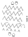
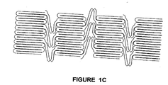
- Figures 1A, 1B, and 1C are stents showing a frangible section contained in its connector members.
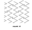
- Figures 2A, 2B, and 2C are stents which contains polymeric bridges adjoining adjacent metallic rings within the stent.
-
- As seen in Figures 1A, 1B, and 1C there is described herein a stent 50 which comprises standard slotted radial rings 100. These rings may be of stainless steel or Nitinol, in a form much like the Palmaz™ or Palmaz-Schatz ™ stent made by Cordis Corporation or the Smart Stent™ also made by Cordis Corporation, Miami Lakes, Florida. These radial rings are intended to be of strong radial strength when emplaced within the body. They may be self-expanding or they may be expanded using a balloon catheter (not shown), so that their expansion is taken beyond the elastic limit of the material so that the stent rings take a permanent set within the body.
- Importantly, the radial rings are connected by flexible connector 150 members spaced around the rings. As seen in the current figures, there are contained three connectors 150 per ring 120, however, it is well known to place multiple connector members and these connectors 150 may be placed as desired on the stent.
- Importantly, about midway along a portion of the connector member 130 there is contained a position of weakness labeled as "A" on Figure 1A. When the stents are emplaced within the body, longitudinal motion of the lumen causes the stents 50 to expand and contract in the longitudinal direction, as seen by the arrows B drawn in Figure 1A and Figure 1B. This causes the notched strain limitor 160 to act as a focal point for the cyclic strain under the loading conditions when elements B and C are deflected in the direction of the arrows. Under these loading conditions, the structure is designed to experience a fatigue fracture in the notched area, A, rather than to communicate stresses or strains throughout the entire structure of stents 50, 50'. This can prevent potentially harmful cyclic strains from causing undesirable fatigue fractures in the radial support members.
- It is noticed that it may be advantageous to maximize the length d and e of a connector 150 so as maximize the fulcrum applied at the section A. This will reduce the time in which it will take the connector member 150 to break apart so that the loads in which the stent is subjected to will be reduced.
- During manufacture, the proposed stent of the current invention is made under typical conventional stent manufacturing methods. However, the notched design 130 may be laser cut or etched into the connector members 150 upon creation, so that during emplacement into the body the connector member is able to be broken as desired. Of course, the stent can be loaded with heparin or other drug coatings, as is now well appreciated in the art. The stent may be made from stainless steel or nitinol or any other biocompatible material.
- As seen in Figure 2A, 2B, and 2C there is contained an alternate embodiment of the current invention. Here, there are polymeric bridges 175 which are placed between the radial rings. The radial rings are quite similar to the radial rings of Figures 1A, 1B and 1C, except that there are contained protrusions F which protrude from either side of the radial rings 120 at a location where it may be desirable to connect one ring to the other ring. The polymeric bridge identified as 175, in Figure 2A, contains slots 180 in which the metallic tab G is emplaced. This tab G also contains a hole H which can be filled with polymer. In other words, during manufacture, the rings are first fashioned using standard cutting techniques, such as laser cutting or etching. The stent rings themselves are made of standard materials such as stainless steel, tantulum, titanium and nickel titanium alloys such as nitinol and the like. After their manufacture, the stent is placed so that the rings are juxtaposed one to the other as seen in Figure 2C. Thereafter, the polymeric bridges may be fused directly to the stents so that the polymer not only surrounds each of the tabs D, but fills the holes E upon manufacture. Thus, the polymer and the polymer that surrounds each of the tabs in multiple fashion so that the polymeric bridge remains integral prior to delivery into the body.
- After delivery, the stents 50, 50' can be expanded using conventional expansion methods such as balloon catheters. Or, the stents may be a self-expanding. In either event, after the stents are expanded within the lumen, the polymeric bridges are subjected to standard corrosive forces located within the body. These corrosive forces cause the breakdown of the polymeric bridge after a certain period of time. This breakdown causes the rings to separate one from the other after a predetermined length of time. It is during this breakdown that the forces which may be caused by cyclic strains caused placed on the stent will become reduced as they only affect one particular ring in one particular location at a time.
- Because the bridge acts as a flexible hinge, it also may improve deployment characteristics. This hinge may be somewhat more flexible during delivery than a standard connector member so that the stent may be able to obtain a position within a slightly more difficult lumens as compared to prior art stents. As constructed, the combined structure of the stent will act as a single stent during delivery and deployment. However, after the polymeric bridges are absorbed the metallic structures forming the rings become completely unconnected and independent of one another. This may be advantageous in vessels which may be subject to longitudinal elongation compressing or bending, as explained above.
- Furthermore, when combined with polymer drug eluting technology, the polymeric bridge may actually provide an additional drug delivery reservoir for the stent. In fact, it may be possible to have a bolus of drug contained within the polymeric at tab E and thereafter delivered in one large dosage upon secretion of the polymeric material into the body.
- Naturally, the stent of the present invention should only be understood in context of the attached claims and their equivalents which are appended as follows.
Claims (8)
- A stent comprising:a plurality of circumferential rings, said rings connected by connector members, andthe connector members designed to be frangible.
- A stent comprising:a plurality of circumferential rings, said rings connected by connector members, andthe connector members being flexible members containing an area of weakness.
- A stent comprising:a plurality of circumferential rings, said rings connected by connector members, andthe connector members being absorbable.
- A stent comprising:a plurality of circumferential rings, said rings connected by connector members, andthe connector members being attached to each ring only at selected points on the ring, andthe connector members being frangible.
- The connector members being attached to each ring only at selected points on the ring, and
the connector members having flexible members containing an area of weakness. - The stent of claims 1 to 5 when the connector member is attached to the ring member at a selected portion on a ring member.
- The stent of claim 1-6 where there is contained a weakened point in the connector member, said weakened point placed about midway between ring members.
- The stent of claim 1-6 where the stent rings are frangible from one another at said connector member upon the application of a predetermined strain on the lumen of a vessel.
Applications Claiming Priority (2)
| Application Number | Priority Date | Filing Date | Title |
|---|---|---|---|
| US10/779,493 US20050182479A1 (en) | 2004-02-13 | 2004-02-13 | Connector members for stents |
| US779493 | 2004-02-13 |
Publications (1)
| Publication Number | Publication Date |
|---|---|
| EP1563806A1 true EP1563806A1 (en) | 2005-08-17 |
Family
ID=34701427
Family Applications (1)
| Application Number | Title | Priority Date | Filing Date |
|---|---|---|---|
| EP05250802A Withdrawn EP1563806A1 (en) | 2004-02-13 | 2005-02-11 | Connector members for stents |
Country Status (3)
| Country | Link |
|---|---|
| US (1) | US20050182479A1 (en) |
| EP (1) | EP1563806A1 (en) |
| CA (1) | CA2494642A1 (en) |
Cited By (14)
| Publication number | Priority date | Publication date | Assignee | Title |
|---|---|---|---|---|
| WO2006087621A1 (en) * | 2005-02-17 | 2006-08-24 | Jacques Seguin | Device allowing the treatment of bodily conduits at an area of a bifurcation |
| FR2911063A1 (en) * | 2007-01-09 | 2008-07-11 | Stentys S A S Soc Par Actions | RUPTIBLE BRIDGE STRUCTURE FOR STENT, AND STENT INCLUDING SUCH BRIDGE STRUCTURES. |
| WO2008030488A3 (en) * | 2006-09-06 | 2008-07-24 | Med Inst Inc | Stents with connectors and stabilizing biodegradable elements |
| EP1958598A1 (en) * | 2007-02-16 | 2008-08-20 | Universität Zürich | Growable tubular support implant |
| EP1958597A1 (en) * | 2007-02-16 | 2008-08-20 | Universität Zürich | Tubular support implant with heart valve in particular for aorta valve replacement |
| WO2008098777A1 (en) * | 2007-02-16 | 2008-08-21 | Universität Zürich | Tubular supporting prosthesis having a heart valve, particularly for aortic valve replacement |
| WO2009009311A3 (en) * | 2007-07-06 | 2009-03-05 | Boston Scient Scimed Inc | Bifurcated stent with bioabsorbable members |
| WO2013131501A1 (en) * | 2012-03-03 | 2013-09-12 | Peter Osypka | Highly flexible stent having a predetermined breaking point |
| US9005274B2 (en) | 2008-08-04 | 2015-04-14 | Stentys Sas | Method for treating a body lumen |
| DE102015108835A1 (en) * | 2015-06-03 | 2016-12-08 | Andratec Gmbh | vessel support |
| US9943426B2 (en) | 2015-07-15 | 2018-04-17 | Elixir Medical Corporation | Uncaging stent |
| US10918505B2 (en) | 2016-05-16 | 2021-02-16 | Elixir Medical Corporation | Uncaging stent |
| WO2023083686A1 (en) * | 2021-11-10 | 2023-05-19 | Mdtec Stent And Catheter Technology Gmbh | Stent with releasable stent sections |
| US12599490B2 (en) | 2017-05-25 | 2026-04-14 | Elixir Medical Corporation | Uncaging stent |
Families Citing this family (107)
| Publication number | Priority date | Publication date | Assignee | Title |
|---|---|---|---|---|
| US6302875B1 (en) | 1996-10-11 | 2001-10-16 | Transvascular, Inc. | Catheters and related devices for forming passageways between blood vessels or other anatomical structures |
| US8353948B2 (en) * | 1997-01-24 | 2013-01-15 | Celonova Stent, Inc. | Fracture-resistant helical stent incorporating bistable cells and methods of use |
| US6799637B2 (en) | 2000-10-20 | 2004-10-05 | Schlumberger Technology Corporation | Expandable tubing and method |
| NO335594B1 (en) | 2001-01-16 | 2015-01-12 | Halliburton Energy Serv Inc | Expandable devices and methods thereof |
| US20070135875A1 (en) | 2002-04-08 | 2007-06-14 | Ardian, Inc. | Methods and apparatus for thermally-induced renal neuromodulation |
| US8150519B2 (en) | 2002-04-08 | 2012-04-03 | Ardian, Inc. | Methods and apparatus for bilateral renal neuromodulation |
| US8347891B2 (en) | 2002-04-08 | 2013-01-08 | Medtronic Ardian Luxembourg S.A.R.L. | Methods and apparatus for performing a non-continuous circumferential treatment of a body lumen |
| US7756583B2 (en) | 2002-04-08 | 2010-07-13 | Ardian, Inc. | Methods and apparatus for intravascularly-induced neuromodulation |
| US20070129761A1 (en) | 2002-04-08 | 2007-06-07 | Ardian, Inc. | Methods for treating heart arrhythmia |
| US20080213331A1 (en) | 2002-04-08 | 2008-09-04 | Ardian, Inc. | Methods and devices for renal nerve blocking |
| US9636174B2 (en) | 2002-04-08 | 2017-05-02 | Medtronic Ardian Luxembourg S.A.R.L. | Methods for therapeutic renal neuromodulation |
| US7617005B2 (en) | 2002-04-08 | 2009-11-10 | Ardian, Inc. | Methods and apparatus for thermally-induced renal neuromodulation |
| DE202004021947U1 (en) | 2003-09-12 | 2013-05-13 | Vessix Vascular, Inc. | Selectable eccentric remodeling and / or ablation of atherosclerotic material |
| US8920414B2 (en) | 2004-09-10 | 2014-12-30 | Vessix Vascular, Inc. | Tuned RF energy and electrical tissue characterization for selective treatment of target tissues |
| US8396548B2 (en) | 2008-11-14 | 2013-03-12 | Vessix Vascular, Inc. | Selective drug delivery in a lumen |
| US9713730B2 (en) | 2004-09-10 | 2017-07-25 | Boston Scientific Scimed, Inc. | Apparatus and method for treatment of in-stent restenosis |
| US20060122694A1 (en) * | 2004-12-03 | 2006-06-08 | Stinson Jonathan S | Medical devices and methods of making the same |
| CN101076290B (en) | 2004-12-09 | 2011-11-23 | 铸造品股份有限公司 | Aortic valve repair |
| US20070100431A1 (en) * | 2005-11-03 | 2007-05-03 | Craig Bonsignore | Intraluminal medical device with strain concentrating bridge |
| US8019435B2 (en) | 2006-05-02 | 2011-09-13 | Boston Scientific Scimed, Inc. | Control of arterial smooth muscle tone |
| US9393135B2 (en) * | 2006-05-12 | 2016-07-19 | CARDINAL HEALTH SWITZERLAND 515 GmbH | Balloon expandable bioabsorbable drug eluting stent |
| ES2407329T3 (en) | 2006-10-18 | 2013-06-12 | Vessix Vascular, Inc. | System to induce desirable temperature effects on body tissue |
| AU2007310986B2 (en) | 2006-10-18 | 2013-07-04 | Boston Scientific Scimed, Inc. | Inducing desirable temperature effects on body tissue |
| US9265636B2 (en) * | 2007-05-25 | 2016-02-23 | C. R. Bard, Inc. | Twisted stent |
| US8114151B2 (en) * | 2008-05-08 | 2012-02-14 | Boston Scientific Scimed, Inc. | Stent with tabs and holes for drug delivery |
| AU2009314133B2 (en) | 2008-11-17 | 2015-12-10 | Vessix Vascular, Inc. | Selective accumulation of energy with or without knowledge of tissue topography |
| US20110066223A1 (en) * | 2009-09-14 | 2011-03-17 | Hossainy Syed F A | Bioabsorbable Stent With Time Dependent Structure And Properties |
| US8425587B2 (en) * | 2009-09-17 | 2013-04-23 | Abbott Cardiovascular Systems Inc. | Method of treatment with a bioabsorbable stent with time dependent structure and properties and regio-selective degradation |
| CA2795229A1 (en) | 2010-04-09 | 2011-10-13 | Vessix Vascular, Inc. | Power generating and control apparatus for the treatment of tissue |
| US9192790B2 (en) | 2010-04-14 | 2015-11-24 | Boston Scientific Scimed, Inc. | Focused ultrasonic renal denervation |
| US8473067B2 (en) | 2010-06-11 | 2013-06-25 | Boston Scientific Scimed, Inc. | Renal denervation and stimulation employing wireless vascular energy transfer arrangement |
| US9358365B2 (en) | 2010-07-30 | 2016-06-07 | Boston Scientific Scimed, Inc. | Precision electrode movement control for renal nerve ablation |
| US9408661B2 (en) | 2010-07-30 | 2016-08-09 | Patrick A. Haverkost | RF electrodes on multiple flexible wires for renal nerve ablation |
| US9155589B2 (en) | 2010-07-30 | 2015-10-13 | Boston Scientific Scimed, Inc. | Sequential activation RF electrode set for renal nerve ablation |
| US9463062B2 (en) | 2010-07-30 | 2016-10-11 | Boston Scientific Scimed, Inc. | Cooled conductive balloon RF catheter for renal nerve ablation |
| US9084609B2 (en) | 2010-07-30 | 2015-07-21 | Boston Scientific Scime, Inc. | Spiral balloon catheter for renal nerve ablation |
| US8974451B2 (en) | 2010-10-25 | 2015-03-10 | Boston Scientific Scimed, Inc. | Renal nerve ablation using conductive fluid jet and RF energy |
| US9220558B2 (en) | 2010-10-27 | 2015-12-29 | Boston Scientific Scimed, Inc. | RF renal denervation catheter with multiple independent electrodes |
| US9028485B2 (en) | 2010-11-15 | 2015-05-12 | Boston Scientific Scimed, Inc. | Self-expanding cooling electrode for renal nerve ablation |
| US9089350B2 (en) | 2010-11-16 | 2015-07-28 | Boston Scientific Scimed, Inc. | Renal denervation catheter with RF electrode and integral contrast dye injection arrangement |
| US9668811B2 (en) | 2010-11-16 | 2017-06-06 | Boston Scientific Scimed, Inc. | Minimally invasive access for renal nerve ablation |
| US9326751B2 (en) | 2010-11-17 | 2016-05-03 | Boston Scientific Scimed, Inc. | Catheter guidance of external energy for renal denervation |
| US9060761B2 (en) | 2010-11-18 | 2015-06-23 | Boston Scientific Scime, Inc. | Catheter-focused magnetic field induced renal nerve ablation |
| US9192435B2 (en) | 2010-11-22 | 2015-11-24 | Boston Scientific Scimed, Inc. | Renal denervation catheter with cooled RF electrode |
| US9023034B2 (en) | 2010-11-22 | 2015-05-05 | Boston Scientific Scimed, Inc. | Renal ablation electrode with force-activatable conduction apparatus |
| US20120157993A1 (en) | 2010-12-15 | 2012-06-21 | Jenson Mark L | Bipolar Off-Wall Electrode Device for Renal Nerve Ablation |
| US9220561B2 (en) | 2011-01-19 | 2015-12-29 | Boston Scientific Scimed, Inc. | Guide-compatible large-electrode catheter for renal nerve ablation with reduced arterial injury |
| EP2694150A1 (en) | 2011-04-08 | 2014-02-12 | Covidien LP | Iontophoresis drug delivery system and method for denervation of the renal sympathetic nerve and iontophoretic drug delivery |
| EP2701623B1 (en) | 2011-04-25 | 2016-08-17 | Medtronic Ardian Luxembourg S.à.r.l. | Apparatus related to constrained deployment of cryogenic balloons for limited cryogenic ablation of vessel walls |
| WO2013013156A2 (en) | 2011-07-20 | 2013-01-24 | Boston Scientific Scimed, Inc. | Percutaneous devices and methods to visualize, target and ablate nerves |
| JP6106669B2 (en) | 2011-07-22 | 2017-04-05 | ボストン サイエンティフィック サイムド,インコーポレイテッドBoston Scientific Scimed,Inc. | A neuromodulation system having a neuromodulation element that can be placed in a helical guide |
| WO2013055826A1 (en) | 2011-10-10 | 2013-04-18 | Boston Scientific Scimed, Inc. | Medical devices including ablation electrodes |
| US10085799B2 (en) | 2011-10-11 | 2018-10-02 | Boston Scientific Scimed, Inc. | Off-wall electrode device and methods for nerve modulation |
| US9420955B2 (en) | 2011-10-11 | 2016-08-23 | Boston Scientific Scimed, Inc. | Intravascular temperature monitoring system and method |
| US9364284B2 (en) | 2011-10-12 | 2016-06-14 | Boston Scientific Scimed, Inc. | Method of making an off-wall spacer cage |
| EP2768568B1 (en) | 2011-10-18 | 2020-05-06 | Boston Scientific Scimed, Inc. | Integrated crossing balloon catheter |
| WO2013058962A1 (en) | 2011-10-18 | 2013-04-25 | Boston Scientific Scimed, Inc. | Deflectable medical devices |
| US8951251B2 (en) | 2011-11-08 | 2015-02-10 | Boston Scientific Scimed, Inc. | Ostial renal nerve ablation |
| EP2779929A1 (en) | 2011-11-15 | 2014-09-24 | Boston Scientific Scimed, Inc. | Device and methods for renal nerve modulation monitoring |
| US9119632B2 (en) | 2011-11-21 | 2015-09-01 | Boston Scientific Scimed, Inc. | Deflectable renal nerve ablation catheter |
| US9265969B2 (en) | 2011-12-21 | 2016-02-23 | Cardiac Pacemakers, Inc. | Methods for modulating cell function |
| US9037259B2 (en) | 2011-12-23 | 2015-05-19 | Vessix Vascular, Inc. | Methods and apparatuses for remodeling tissue of or adjacent to a body passage |
| CN104135958B (en) | 2011-12-28 | 2017-05-03 | 波士顿科学西美德公司 | Devices and methods for modulating nerves with novel ablation catheters having polymeric ablation elements |
| US9050106B2 (en) | 2011-12-29 | 2015-06-09 | Boston Scientific Scimed, Inc. | Off-wall electrode device and methods for nerve modulation |
| US9254212B2 (en) | 2012-04-06 | 2016-02-09 | Abbott Cardiovascular Systems Inc. | Segmented scaffolds and delivery thereof for peripheral applications |
| WO2013169927A1 (en) | 2012-05-08 | 2013-11-14 | Boston Scientific Scimed, Inc. | Renal nerve modulation devices |
| US8834556B2 (en) | 2012-08-13 | 2014-09-16 | Abbott Cardiovascular Systems Inc. | Segmented scaffold designs |
| WO2014032016A1 (en) | 2012-08-24 | 2014-02-27 | Boston Scientific Scimed, Inc. | Intravascular catheter with a balloon comprising separate microporous regions |
| EP2895095A2 (en) | 2012-09-17 | 2015-07-22 | Boston Scientific Scimed, Inc. | Self-positioning electrode system and method for renal nerve modulation |
| US10398464B2 (en) | 2012-09-21 | 2019-09-03 | Boston Scientific Scimed, Inc. | System for nerve modulation and innocuous thermal gradient nerve block |
| WO2014047454A2 (en) | 2012-09-21 | 2014-03-27 | Boston Scientific Scimed, Inc. | Self-cooling ultrasound ablation catheter |
| CN104869930B (en) | 2012-10-10 | 2020-12-25 | 波士顿科学国际有限公司 | Renal neuromodulation apparatus and methods |
| US9956033B2 (en) | 2013-03-11 | 2018-05-01 | Boston Scientific Scimed, Inc. | Medical devices for modulating nerves |
| WO2014143571A1 (en) | 2013-03-11 | 2014-09-18 | Boston Scientific Scimed, Inc. | Medical devices for modulating nerves |
| US9808311B2 (en) | 2013-03-13 | 2017-11-07 | Boston Scientific Scimed, Inc. | Deflectable medical devices |
| EP2967734B1 (en) | 2013-03-15 | 2019-05-15 | Boston Scientific Scimed, Inc. | Methods and apparatuses for remodeling tissue of or adjacent to a body passage |
| JP6139772B2 (en) | 2013-03-15 | 2017-05-31 | ボストン サイエンティフィック サイムド,インコーポレイテッドBoston Scientific Scimed,Inc. | Control unit for use with electrode pads and method for estimating leakage |
| US10265122B2 (en) | 2013-03-15 | 2019-04-23 | Boston Scientific Scimed, Inc. | Nerve ablation devices and related methods of use |
| US10022182B2 (en) | 2013-06-21 | 2018-07-17 | Boston Scientific Scimed, Inc. | Medical devices for renal nerve ablation having rotatable shafts |
| WO2014205388A1 (en) | 2013-06-21 | 2014-12-24 | Boston Scientific Scimed, Inc. | Renal denervation balloon catheter with ride along electrode support |
| US9707036B2 (en) | 2013-06-25 | 2017-07-18 | Boston Scientific Scimed, Inc. | Devices and methods for nerve modulation using localized indifferent electrodes |
| JP6204579B2 (en) | 2013-07-01 | 2017-09-27 | ボストン サイエンティフィック サイムド,インコーポレイテッドBoston Scientific Scimed,Inc. | Renal nerve ablation medical device |
| WO2015006480A1 (en) | 2013-07-11 | 2015-01-15 | Boston Scientific Scimed, Inc. | Devices and methods for nerve modulation |
| EP3019106A1 (en) | 2013-07-11 | 2016-05-18 | Boston Scientific Scimed, Inc. | Medical device with stretchable electrode assemblies |
| EP3049007B1 (en) | 2013-07-19 | 2019-06-12 | Boston Scientific Scimed, Inc. | Spiral bipolar electrode renal denervation balloon |
| WO2015013301A1 (en) | 2013-07-22 | 2015-01-29 | Boston Scientific Scimed, Inc. | Renal nerve ablation catheter having twist balloon |
| US10342609B2 (en) | 2013-07-22 | 2019-07-09 | Boston Scientific Scimed, Inc. | Medical devices for renal nerve ablation |
| US9717609B2 (en) | 2013-08-01 | 2017-08-01 | Abbott Cardiovascular Systems Inc. | Variable stiffness stent |
| US10722300B2 (en) | 2013-08-22 | 2020-07-28 | Boston Scientific Scimed, Inc. | Flexible circuit having improved adhesion to a renal nerve modulation balloon |
| WO2015035047A1 (en) | 2013-09-04 | 2015-03-12 | Boston Scientific Scimed, Inc. | Radio frequency (rf) balloon catheter having flushing and cooling capability |
| EP3043733A1 (en) | 2013-09-13 | 2016-07-20 | Boston Scientific Scimed, Inc. | Ablation balloon with vapor deposited cover layer |
| KR20160065091A (en) * | 2013-09-27 | 2016-06-08 | 테루모 가부시키가이샤 | Stent |
| US11246654B2 (en) | 2013-10-14 | 2022-02-15 | Boston Scientific Scimed, Inc. | Flexible renal nerve ablation devices and related methods of use and manufacture |
| CN105592778B (en) | 2013-10-14 | 2019-07-23 | 波士顿科学医学有限公司 | High Resolution Cardiac Mapping Electrode Array Catheter |
| JP6259098B2 (en) | 2013-10-15 | 2018-01-10 | ボストン サイエンティフィック サイムド,インコーポレイテッドBoston Scientific Scimed,Inc. | Medical device and method for manufacturing the medical device |
| US9770606B2 (en) | 2013-10-15 | 2017-09-26 | Boston Scientific Scimed, Inc. | Ultrasound ablation catheter with cooling infusion and centering basket |
| JP6259099B2 (en) | 2013-10-18 | 2018-01-10 | ボストン サイエンティフィック サイムド,インコーポレイテッドBoston Scientific Scimed,Inc. | Balloon catheter comprising a conductive wire with flexibility, and related uses and manufacturing methods |
| CN105658163B (en) | 2013-10-25 | 2020-08-18 | 波士顿科学国际有限公司 | Embedded Thermocouples in Denervated Flexible Circuits |
| US11202671B2 (en) | 2014-01-06 | 2021-12-21 | Boston Scientific Scimed, Inc. | Tear resistant flex circuit assembly |
| US11000679B2 (en) | 2014-02-04 | 2021-05-11 | Boston Scientific Scimed, Inc. | Balloon protection and rewrapping devices and related methods of use |
| US9907609B2 (en) | 2014-02-04 | 2018-03-06 | Boston Scientific Scimed, Inc. | Alternative placement of thermal sensors on bipolar electrode |
| US10709490B2 (en) | 2014-05-07 | 2020-07-14 | Medtronic Ardian Luxembourg S.A.R.L. | Catheter assemblies comprising a direct heating element for renal neuromodulation and associated systems and methods |
| US10675707B2 (en) * | 2017-04-19 | 2020-06-09 | Medtronic Vascular, Inc. | Method of making a medical device using additive manufacturing |
| US10849769B2 (en) * | 2017-08-23 | 2020-12-01 | Vesper Medical, Inc. | Non-foreshortening stent |
| US11116561B2 (en) | 2018-01-24 | 2021-09-14 | Medtronic Ardian Luxembourg S.A.R.L. | Devices, agents, and associated methods for selective modulation of renal nerves |
| US10821011B2 (en) | 2018-03-11 | 2020-11-03 | Medtronic Vascular, Inc. | Medical device and method of manufacturing using micro-cladding to form functionally graded materials |
| US20200138610A1 (en) * | 2018-07-17 | 2020-05-07 | Cook Medical Technologies Llc | Stent having a stent body and detachable anchor portion |
Citations (5)
| Publication number | Priority date | Publication date | Assignee | Title |
|---|---|---|---|---|
| WO2000032136A1 (en) * | 1998-12-03 | 2000-06-08 | Medinol Ltd. | Controlled detachment stents |
| WO2000062708A1 (en) * | 1999-04-15 | 2000-10-26 | Mayo Foundation For Medical Education And Research | Multi-section stent |
| US20020151964A1 (en) * | 1999-07-02 | 2002-10-17 | Scimed Life Systems, Inc. | Flexible segmented stent |
| WO2003020102A2 (en) * | 2001-09-06 | 2003-03-13 | Medinol Ltd. | Self articulating stent |
| WO2003047651A2 (en) * | 2001-12-03 | 2003-06-12 | Xtent, Inc. | Apparatus and methods for delivery of multiple distributed stents |
Family Cites Families (2)
| Publication number | Priority date | Publication date | Assignee | Title |
|---|---|---|---|---|
| US7029492B1 (en) * | 1999-03-05 | 2006-04-18 | Terumo Kabushiki Kaisha | Implanting stent and dilating device |
| US7137993B2 (en) * | 2001-12-03 | 2006-11-21 | Xtent, Inc. | Apparatus and methods for delivery of multiple distributed stents |
-
2004
- 2004-02-13 US US10/779,493 patent/US20050182479A1/en not_active Abandoned
-
2005
- 2005-01-21 CA CA002494642A patent/CA2494642A1/en not_active Abandoned
- 2005-02-11 EP EP05250802A patent/EP1563806A1/en not_active Withdrawn
Patent Citations (5)
| Publication number | Priority date | Publication date | Assignee | Title |
|---|---|---|---|---|
| WO2000032136A1 (en) * | 1998-12-03 | 2000-06-08 | Medinol Ltd. | Controlled detachment stents |
| WO2000062708A1 (en) * | 1999-04-15 | 2000-10-26 | Mayo Foundation For Medical Education And Research | Multi-section stent |
| US20020151964A1 (en) * | 1999-07-02 | 2002-10-17 | Scimed Life Systems, Inc. | Flexible segmented stent |
| WO2003020102A2 (en) * | 2001-09-06 | 2003-03-13 | Medinol Ltd. | Self articulating stent |
| WO2003047651A2 (en) * | 2001-12-03 | 2003-06-12 | Xtent, Inc. | Apparatus and methods for delivery of multiple distributed stents |
Cited By (27)
| Publication number | Priority date | Publication date | Assignee | Title |
|---|---|---|---|---|
| WO2006087621A1 (en) * | 2005-02-17 | 2006-08-24 | Jacques Seguin | Device allowing the treatment of bodily conduits at an area of a bifurcation |
| US9192492B2 (en) | 2005-02-17 | 2015-11-24 | Jacques Seguin | Device allowing the treatment of bodily conduits at an area of a bifurcation |
| WO2008030488A3 (en) * | 2006-09-06 | 2008-07-24 | Med Inst Inc | Stents with connectors and stabilizing biodegradable elements |
| FR2911063A1 (en) * | 2007-01-09 | 2008-07-11 | Stentys S A S Soc Par Actions | RUPTIBLE BRIDGE STRUCTURE FOR STENT, AND STENT INCLUDING SUCH BRIDGE STRUCTURES. |
| WO2008084376A3 (en) * | 2007-01-09 | 2008-10-16 | Stentys S A S | Frangible bridge structure for a stent, and stent including such bridge structures |
| US8070794B2 (en) | 2007-01-09 | 2011-12-06 | Stentys S.A.S. | Frangible bridge structure for a stent, and stent including such bridge structures |
| EP1958598A1 (en) * | 2007-02-16 | 2008-08-20 | Universität Zürich | Growable tubular support implant |
| EP1958597A1 (en) * | 2007-02-16 | 2008-08-20 | Universität Zürich | Tubular support implant with heart valve in particular for aorta valve replacement |
| WO2008098776A1 (en) | 2007-02-16 | 2008-08-21 | Universität Zürich | Tubular supporting prosthesis capable of growing |
| WO2008098777A1 (en) * | 2007-02-16 | 2008-08-21 | Universität Zürich | Tubular supporting prosthesis having a heart valve, particularly for aortic valve replacement |
| WO2009009311A3 (en) * | 2007-07-06 | 2009-03-05 | Boston Scient Scimed Inc | Bifurcated stent with bioabsorbable members |
| US7632305B2 (en) | 2007-07-06 | 2009-12-15 | Boston Scientific Scimed, Inc. | Biodegradable connectors |
| US9005274B2 (en) | 2008-08-04 | 2015-04-14 | Stentys Sas | Method for treating a body lumen |
| WO2013131501A1 (en) * | 2012-03-03 | 2013-09-12 | Peter Osypka | Highly flexible stent having a predetermined breaking point |
| US20150366685A1 (en) * | 2012-03-03 | 2015-12-24 | Peter Osypka | Highly flexible stent having a predetermined breaking point |
| US9433519B2 (en) | 2012-03-03 | 2016-09-06 | Peter Osypka | Highly flexible stent having a predetermined breaking point |
| DE102015108835A1 (en) * | 2015-06-03 | 2016-12-08 | Andratec Gmbh | vessel support |
| US9943426B2 (en) | 2015-07-15 | 2018-04-17 | Elixir Medical Corporation | Uncaging stent |
| US10271976B2 (en) | 2016-05-16 | 2019-04-30 | Elixir Medical Corporation | Uncaging stent |
| US10076431B2 (en) | 2016-05-16 | 2018-09-18 | Elixir Medical Corporation | Uncaging stent |
| US10383750B1 (en) | 2016-05-16 | 2019-08-20 | Elixir Medical Corporation | Uncaging stent |
| US10786374B2 (en) | 2016-05-16 | 2020-09-29 | Elixir Medical Corporation | Uncaging stent |
| US10918505B2 (en) | 2016-05-16 | 2021-02-16 | Elixir Medical Corporation | Uncaging stent |
| US11622872B2 (en) | 2016-05-16 | 2023-04-11 | Elixir Medical Corporation | Uncaging stent |
| US12011378B2 (en) | 2016-05-16 | 2024-06-18 | Elixir Medical Corporation | Uncaging stent |
| US12599490B2 (en) | 2017-05-25 | 2026-04-14 | Elixir Medical Corporation | Uncaging stent |
| WO2023083686A1 (en) * | 2021-11-10 | 2023-05-19 | Mdtec Stent And Catheter Technology Gmbh | Stent with releasable stent sections |
Also Published As
| Publication number | Publication date |
|---|---|
| US20050182479A1 (en) | 2005-08-18 |
| CA2494642A1 (en) | 2005-08-13 |
Similar Documents
| Publication | Publication Date | Title |
|---|---|---|
| US20050182479A1 (en) | Connector members for stents | |
| US6607554B2 (en) | Universal stent link design | |
| US10463511B2 (en) | Stent having at least one connecting member configured to controllably sever in vivo | |
| EP2134301B1 (en) | Bendable stent | |
| US20130211499A1 (en) | Intraluminal medical device with strain concentrating bridge | |
| US6969401B1 (en) | Endovascular prosthesis | |
| US6695876B1 (en) | Endovascular prosthesis | |
| EP2849688B1 (en) | Uniformly expandable stent | |
| US9237959B2 (en) | Stent and barb | |
| US20080269872A1 (en) | Stent | |
| US20040015229A1 (en) | Vascular stent with radiopaque markers | |
| WO2001026584A1 (en) | Stents with multilayered struts | |
| US9717609B2 (en) | Variable stiffness stent | |
| WO2000047134A1 (en) | Endovascular prosthesis | |
| CN102309370A (en) | Flexible stent | |
| EP3134140B1 (en) | Bioerodible stent | |
| JP2019535370A (en) | Double stent | |
| US20190021886A1 (en) | Segmented self-expanding stent | |
| US11759340B2 (en) | Optimised structure for an expandable implant of the stent or endoprosthesis type | |
| EP1895934B1 (en) | Intraluminal device with improved tapered beams | |
| EP3998050B1 (en) | Stent and affixing method for element wires in stent | |
| EP2489337B1 (en) | Prosthesis and method of manufacture | |
| EP3242641A1 (en) | Endoluminal stent | |
| AU2009202392B2 (en) | Endovascular prosthesis |
Legal Events
| Date | Code | Title | Description |
|---|---|---|---|
| PUAI | Public reference made under article 153(3) epc to a published international application that has entered the european phase |
Free format text: ORIGINAL CODE: 0009012 |
|
| AK | Designated contracting states |
Kind code of ref document: A1 Designated state(s): AT BE BG CH CY CZ DE DK EE ES FI FR GB GR HU IE IS IT LI LT LU MC NL PL PT RO SE SI SK TR |
|
| AX | Request for extension of the european patent |
Extension state: AL BA HR LV MK YU |
|
| 17P | Request for examination filed |
Effective date: 20060130 |
|
| AKX | Designation fees paid |
Designated state(s): AT BE BG CH CY CZ DE DK EE ES FI FR GB GR HU IE IS IT LI LT LU MC NL PL PT RO SE SI SK TR |
|
| 17Q | First examination report despatched |
Effective date: 20080901 |
|
| STAA | Information on the status of an ep patent application or granted ep patent |
Free format text: STATUS: THE APPLICATION IS DEEMED TO BE WITHDRAWN |
|
| 18D | Application deemed to be withdrawn |
Effective date: 20090113 |