EP1563799A1 - Adjustable marker arrangement - Google Patents
Adjustable marker arrangement Download PDFInfo
- Publication number
- EP1563799A1 EP1563799A1 EP04003019A EP04003019A EP1563799A1 EP 1563799 A1 EP1563799 A1 EP 1563799A1 EP 04003019 A EP04003019 A EP 04003019A EP 04003019 A EP04003019 A EP 04003019A EP 1563799 A1 EP1563799 A1 EP 1563799A1
- Authority
- EP
- European Patent Office
- Prior art keywords
- reference star
- joint
- bearing
- instrument
- adapter
- Prior art date
- Legal status (The legal status is an assumption and is not a legal conclusion. Google has not performed a legal analysis and makes no representation as to the accuracy of the status listed.)
- Granted
Links
- 239000003550 marker Substances 0.000 title abstract description 8
- 238000000034 method Methods 0.000 claims abstract description 12
- 238000004590 computer program Methods 0.000 claims abstract description 7
- 238000001356 surgical procedure Methods 0.000 description 2
- 210000000988 bone and bone Anatomy 0.000 description 1
- 239000003795 chemical substances by application Substances 0.000 description 1
- 230000001419 dependent effect Effects 0.000 description 1
- 238000001514 detection method Methods 0.000 description 1
- 238000006073 displacement reaction Methods 0.000 description 1
- 230000000694 effects Effects 0.000 description 1
Images

Classifications
-
- A—HUMAN NECESSITIES
- A61—MEDICAL OR VETERINARY SCIENCE; HYGIENE
- A61B—DIAGNOSIS; SURGERY; IDENTIFICATION
- A61B90/00—Instruments, implements or accessories specially adapted for surgery or diagnosis and not covered by any of the groups A61B1/00 - A61B50/00, e.g. for luxation treatment or for protecting wound edges
- A61B90/39—Markers, e.g. radio-opaque or breast lesions markers
-
- A—HUMAN NECESSITIES
- A61—MEDICAL OR VETERINARY SCIENCE; HYGIENE
- A61B—DIAGNOSIS; SURGERY; IDENTIFICATION
- A61B17/00—Surgical instruments, devices or methods, e.g. tourniquets
- A61B2017/0046—Surgical instruments, devices or methods, e.g. tourniquets with a releasable handle; with handle and operating part separable
-
- A—HUMAN NECESSITIES
- A61—MEDICAL OR VETERINARY SCIENCE; HYGIENE
- A61B—DIAGNOSIS; SURGERY; IDENTIFICATION
- A61B34/00—Computer-aided surgery; Manipulators or robots specially adapted for use in surgery
- A61B34/20—Surgical navigation systems; Devices for tracking or guiding surgical instruments, e.g. for frameless stereotaxis
- A61B2034/2046—Tracking techniques
- A61B2034/2055—Optical tracking systems
-
- A—HUMAN NECESSITIES
- A61—MEDICAL OR VETERINARY SCIENCE; HYGIENE
- A61B—DIAGNOSIS; SURGERY; IDENTIFICATION
- A61B90/00—Instruments, implements or accessories specially adapted for surgery or diagnosis and not covered by any of the groups A61B1/00 - A61B50/00, e.g. for luxation treatment or for protecting wound edges
- A61B90/08—Accessories or related features not otherwise provided for
- A61B2090/0807—Indication means
- A61B2090/0811—Indication means for the position of a particular part of an instrument with respect to the rest of the instrument, e.g. position of the anvil of a stapling instrument
-
- A—HUMAN NECESSITIES
- A61—MEDICAL OR VETERINARY SCIENCE; HYGIENE
- A61B—DIAGNOSIS; SURGERY; IDENTIFICATION
- A61B90/00—Instruments, implements or accessories specially adapted for surgery or diagnosis and not covered by any of the groups A61B1/00 - A61B50/00, e.g. for luxation treatment or for protecting wound edges
- A61B90/39—Markers, e.g. radio-opaque or breast lesions markers
- A61B2090/3983—Reference marker arrangements for use with image guided surgery
-
- A—HUMAN NECESSITIES
- A61—MEDICAL OR VETERINARY SCIENCE; HYGIENE
- A61B—DIAGNOSIS; SURGERY; IDENTIFICATION
- A61B34/00—Computer-aided surgery; Manipulators or robots specially adapted for use in surgery
- A61B34/20—Surgical navigation systems; Devices for tracking or guiding surgical instruments, e.g. for frameless stereotaxis
Definitions
- the present invention relates to an adjustable marker assembly and in particular to a marker system, which is equipped with a medical navigation system can be used, wherein the marker system has an adapter to which a Reference star can be attached and which on a body, such as a patient or an instrument can be attached to the position of the Patient or instrument for example during a medical procedure determine.
- Medical navigation systems such as image-based systems allow That is, for example, a surgeon can perform navigation information by registering before the operation takes pictures of a patient provided. There may also be surgical instruments following a calibration procedure for example, the position of an instrument during an intervention relative to the images of a body structure taken before the procedure can be.
- Navigation systems use a computer with which one or more so-called Tracking sensors or cameras are connected, so the position of markers can be determined which attached to a patient and / or instruments which determines the position of the patient and / or the instruments can.
- markers can be both active emitters and so-called passive reflective ones Be markers, which with adapters on a patient and / or on surgical Instruments, such as a scalpel, forceps, a microscope or a Pointer can be attached.
- an adapter which is a first fastener, such as a bracket, for attachment, for example on an instrument on one side and a second fastener for Example of a reference star with three or more outward-extending arms on the other side, being reflective at the outer ends of the arms Markers can be attached or attached.
- a known navigation system using the reference stars described above is the image-based navigation system VectorVision TM available from BrainLAB AG and is described, for example, in US 2003/0225329 A1.
- Reference stars placed within a limited workspace of a surgeon
- These reference stars advantageously have different geometries in order to Example to differentiate different instruments.
- the use may be several reference stars cause them within the field of view of a camera cover, or that individual markers or reference stars by objects or Persons are obscured or hinder the activity of the surgeon.
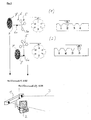
- the body or limb of the patient is being moved, it may cause this movement that a fixed to the body 7 reference star 5 not more can be detected by the cameras 1, as shown for example in FIG. 1B. If the reference star adapter 6 were detached from the body 7, around the reference star 5 again in a different position to attach to the object in which he from the cameras 1, the patient would have to be re-registered.
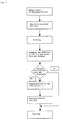
- FIG. 1 A flowchart illustrating the steps in a movement of the reference star from the field of view of the cameras is shown in FIG.
- a reference star adapter has a first fastening element, such as a clip for attaching the adapter to a Instrument or a screw for attaching the adapter to a body, such as for example, a bone, and has a second fastener on which the reference star or the individual markers can be attached.
- a first fastening element such as a clip for attaching the adapter to a Instrument or a screw for attaching the adapter to a body, such as for example, a bone
- the second fastener is between the first fastener for mounting the adapter on a body or an instrument and the second fastener for Mounting the reference star or the marker provided at least one bearing or joint, which allows the second fastener relative to the first Fastener can be adjusted, according to the invention with the camp a active or passive position detector is connected, which provides data which the Describe or define the position or geometry of the at least one bearing.
- a position detector provided according to the invention can, for example a on a body or instrument with the inventively designed reference star adapter fixed reference star automatically or manually repositioned, for example, rotated around one or more joints and / or along one or more joints several predetermined directions are shifted, wherein by at least one Position detector can be determined which movement of the reference star in relation to his previous position.
- a new registration or Calibration is not required because of the signal passing through the at least one position detector determined change in position of the reference star the new positional relationship between the Reference star and the body or instrument connected to this reference star
- the reference star again in a defined positional relationship to this body or instrument is, if a referencing or calibration was carried out before. consequently it is not necessary that after changing the position of the reference star a new registration or calibration is performed, which makes it easier during a surgical procedure to reposition one or more reference stars and then continue to work without major loss of time.
- At least one bearing can be a floating bearing, such as a radial bearing, plain bearings or roller bearings, but also a fixed bearing, such as a transverse and longitudinal bearings or a firm joint.
- the bearing can also be used as a swivel joint, sliding joint, curve joint, Screw joint, rotary push joint, ball joint or plate joint formed be.
- a hinge or bearing of the reference star adapter may be configured that the joint only at defined predetermined positions for example can be detected or locked by a toothing or locking, wherein
- a latching mechanism is provided on a hinge or bearing, which although it allows the joint to be moved continuously, however a stable state is present only at certain predetermined locking positions.
- the bearing or joint Be provided markers, which are used as position detectors, so that a user of the reference star adapter according to the invention at the mark of the bearing or joint can read in which position the joint or bearing currently located.
- a continuously adjustable bearing or joint is used, so it is also possible that a continuous display is provided, which, for example at a hinge indicating the opening angle of the joint, so that a For example, users can read after locking the joint like the current one State of the joint is or how much the location of the joint or the associated Reference star was changed.
- position or position sensors are provided on one or more joints or bearings, which the Measure or detect movement of a joint or bearing.
- a rotation such as for example, an opening angle of a joint or a translation, such as can quantitatively determine the displacement of a supported axis, the for example, displayed and entered manually and / or can be automatically transmitted to the navigation system.
- a rotation such as for example, an opening angle of a joint or a translation
- the individual position sensors via cable, radio, such as Bluetooth, or a Infrared interface can be connected to the navigation system, to the position or to convey the change in the position of the reference star to the navigation system.
- the reference star adapter according to the invention can be semi-automatic or automatic be formed by one or more motors are provided with which the reference star can be moved, according to the invention either to a motor a position or position detector is provided, or the motor operated as a servomotor is, so that caused by the engine positional change of the reference star is precisely defined and thus can be transmitted to the navigation system.
- the invention relates to a navigation system with at least one reference star adapter as described above and a reference star, further provided with a camera and an associated computing unit could be.
- the invention in another aspect, relates to a method for recalibration and / or re-referencing a body or instrument with an attached one Reference star, where the position of the reference star relative to the body or Instrument is changed and detects the change in the position of the reference star becomes, so that from the detected change in the position of the reference star the new positional relationship between the reference star and the body or instrument determined so that recalibration or re-referencing can be done easily can be.
- the change in the position of the reference star automatically to the Transmit navigation system, so for example, a continuous recalibration or re-referencing during movement of the reference star relative to the Body or instrument can be performed. It is also possible to recalibrate or re-referencing only after the position change using perform the detected position change data.
- the geometry or structure of the adapter and / or the at least one Joint or bearing stored in a database.
- the invention further relates to a computer program which, when in a computer is loaded or running on a computer, as described above Performs procedure. Furthermore, the invention relates to a program storage medium or a computer program product with such a program.
- Figure 1 shows a navigation system, wherein cameras 1 have a field of view 3 and the on can detect a reference star 5 provided passive marker 5a.
- the of the Cameras 1 detected position of the marker 5a is passed to a computing unit 2.
- the reference star 5 is by means of an adapter 6 with a body 7 by a fastener 8, which was referenced in a known manner.
- the reference star adapter 6 By the reference star adapter 6 according to the invention, it is possible that the reference star 5 remains connected to the body 7 and by a manual or automatic Movement of the provided on the reference star adapter 6 joint 6a so shifted and / or worked that the reference star 5 back into the detection area 3 of Cameras 1 arrives.
- a sensor or decoder is provided, which can detect the quantitative movement of the joint 6a and this quantitative information to the arithmetic unit 2 of the navigation system automatically or transmitted by manual input, the body 7 can simply be re-referenced be determined by the change in position of the reference star 5, which the new positional relationship between the reference star 5 and the body 7 simply determined or can be calculated; if the geometry or structure of the adapter 6 or the joint 6a is known.
- FIG. 2 shows an embodiment of an adjustment mechanism of the reference star adapter 6 according to the present invention.
- a reference star 5 is with a body or instrument 7 connected by means of the reference star adapter 6, which has an adjusting mechanism 6a, which consists of a rotary joint A and a sliding bearing B.
- the Swivel A can engage in six different rotational positions 1 to 6, wherein in the shown starting position (1) is the pivot A in the position "1".
- the sliding bearing B can be locked in four different positions 1 to 4, wherein in the shown Starting position (1) the sliding bearing B is locked in position 2.
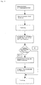
- FIG. 3 shows a flowchart for re-registering a patient after the adjustment the position of a connected to the patient via an adapter according to the invention Reference star.
- the patient becomes, for example, a certain Body structure of the patient, registered and the registered structure can be tracked become. If the registered structure is moved out of the field of view 3 of the cameras 1, then can first be tried, whether by adjusting the cameras of the reference star returned to the field of view. If this fails, the reference star becomes a new one Position brought and the navigation system or the software is an example in Figure 2 notified new position code, so that from the new positional relationship is calculated and it is possible then to track the then re-registered structure.
Abstract
Description
Die vorliegende Erfindung bezieht sich auf eine verstellbare Markeranordnung und insbesondere auf ein Markersystem, welches mit einem medizinischen Navigationssystem verwendet werden kann, wobei das Markersystem einen Adapter aufweist, an welchem ein Referenzstern befestigt werden kann und welcher an einem Körper, wie zum Beispiel an einem Patienten oder an einem Instrument angebracht werden kann, um die Position des Patienten oder des Instrumentes zum Beispiel während eines medizinischen Verfahrens zu ermitteln.The present invention relates to an adjustable marker assembly and in particular to a marker system, which is equipped with a medical navigation system can be used, wherein the marker system has an adapter to which a Reference star can be attached and which on a body, such as a patient or an instrument can be attached to the position of the Patient or instrument for example during a medical procedure determine.
Medizinische Navigationssysteme, wie zum Beispiel bildgestützte Systeme, ermöglichen es, dass zum Beispiel ein Chirurg eine Navigationsinformation durch das Registrieren von vor der Operation aufgenommenen Bildern eines Patienten zur Verfügung gestellt bekommt. Es können auch chirurgische Instrumente nach einem Kalibrierungsverfahren navigiert werden, wobei zum Beispiel die Position eines Instrumentes während eines Eingriffs relativ zu den vor dem Eingriff aufgenommenen Bildern einer Körperstruktur dargestellt werden kann.Medical navigation systems, such as image-based systems allow That is, for example, a surgeon can perform navigation information by registering before the operation takes pictures of a patient provided. There may also be surgical instruments following a calibration procedure for example, the position of an instrument during an intervention relative to the images of a body structure taken before the procedure can be.
Navigationssysteme verwenden einen Computer, mit welchem ein oder mehrere sogenannte Tracking-Sensoren oder Kameras verbunden sind, so dass die Position von Markern ermittelt werden kann, welche an einem Patienten und/oder an Instrumenten befestigt sind, wodurch die Position des Patienten und/oder der Instrumente bestimmt werden kann. Solche Marker können sowohl aktive Emitter, als auch sogenannte passive reflektierende Marker sein, welche mit Adaptern an einem Patienten und/oder an chirurgischen Instrumenten, wie zum Beispiel einem Skalpell, einer Zange, einem Mikroskop oder einem Pointer angebracht werden können. Häufig wird ein Adapter verwendet, welcher ein erstes Befestigungselement, wie zum Beispiel eine Klammer, zur Anbringung zum Beispiel an einem Instrument auf der einen Seite und ein zweites Befestigungselement zum Beispiel für einen Referenzstern mit drei oder mehr sich nach außen erstreckenden Armen an der anderen Seite aufweist, wobei an den äußeren Enden der Arme reflektierende Marker angebracht werden können oder angebracht sind.Navigation systems use a computer with which one or more so-called Tracking sensors or cameras are connected, so the position of markers can be determined which attached to a patient and / or instruments which determines the position of the patient and / or the instruments can. Such markers can be both active emitters and so-called passive reflective ones Be markers, which with adapters on a patient and / or on surgical Instruments, such as a scalpel, forceps, a microscope or a Pointer can be attached. Often an adapter is used, which is a first fastener, such as a bracket, for attachment, for example on an instrument on one side and a second fastener for Example of a reference star with three or more outward-extending arms on the other side, being reflective at the outer ends of the arms Markers can be attached or attached.
Ein bekanntes Navigationssystem, welches die oben beschriebenen Referenzsterne verwendet, ist das von der BrainLAB AG erhältliche bildgestützte Navigationssystem VectorVision™ und ist zum Beispiel in der US 2003/0225329 A1 beschrieben.A known navigation system using the reference stars described above, is the image-based navigation system VectorVision ™ available from BrainLAB AG and is described, for example, in US 2003/0225329 A1.
Während eines chirurgischen Eingriffes kann es vorkommen, dass zum Beispiel mehrere
Referenzsterne innerhalb eines begrenzten Arbeitsbereiches eines Chirurgen angebracht
sind, wobei diese Referenzsterne vorteilhaft unterschiedliche Geometrien haben, um zum
Beispiel verschiedene Instrumente unterscheiden zu können. Jedoch kann die Verwendung
mehrerer Referenzsterne dazu führen, dass sich diese innerhalb des Sichtfeldes einer Kamera
überdecken, oder dass einzelne Marker oder Referenzsterne durch Objekte oder
Personen verdeckt werden oder auch die Tätigkeit des Chirurgen behindern. Insbesondere,
wenn zum Beispiel der Körper oder eine Extremität des Patienten bewegt wird, kann
diese Bewegung dazu führen, dass ein an dem Körper 7 befestigter Referenzstern 5 nicht
mehr von den Kameras 1 entdeckt werden kann, wie zum Beispiel in Figur 1B gezeigt.
Würde der Referenzsternadapter 6 von dem Körper 7 gelöst, um den Referenzstern 5
wieder in einer anderen Position an dem Objekt anzubringen, in welcher er von den Kameras
1 erkannt werden kann, müsste der Patient neu registriert werden.During a surgical procedure, it may happen that, for example, several
Reference stars placed within a limited workspace of a surgeon
These reference stars advantageously have different geometries in order to
Example to differentiate different instruments. However, the use may be
several reference stars cause them within the field of view of a camera
cover, or that individual markers or reference stars by objects or
Persons are obscured or hinder the activity of the surgeon. Especially,
For example, if the body or limb of the patient is being moved, it may
cause this movement that a fixed to the
Ein Ablaufdiagramm zur Veranschaulichung der Schritte bei einer Bewegung des Referenzsterns aus dem Sichtfeld der Kameras ist in Figur 4 gezeigt.A flowchart illustrating the steps in a movement of the reference star from the field of view of the cameras is shown in FIG.
Es ist eine Aufgabe der vorliegenden Erfindung einen Referenzsternadapter und ein Verfahren zum Neukalibrieren oder Neureferenzieren eines Instruments oder Körpers vorzuschlagen, welche bildgestützte chirurgische System effizienter und schneller machen können. It is an object of the present invention to provide a reference star adapter and a method to recalibrate or re-reference an instrument or body, which can make image-guided surgical systems more efficient and faster.
Diese Aufgabe wird durch die in den unabhängigen Ansprüchen definierten Erfindungen gelöst. Vorteilhafte Ausführungsformen ergeben sich aus den Unteransprüchen.This object is achieved by the inventions defined in the independent claims solved. Advantageous embodiments will be apparent from the dependent claims.
Gemäß einem ersten Aspekt der Erfindung weist ein Referenzsternadapter ein erstes Befestigungselement, wie zum Beispiel eine Klammer zur Befestigung des Adapters an einem Instrument oder eine Schraube zur Befestigung des Adapters an einem Körper, wie zum Beispiel einem Knochen, auf und weist ein zweites Befestigungselement auf, an welchem der Referenzstern oder auch die einzelnen Marker angebracht werden können. Erfindungsgemäß ist zwischen dem ersten Befestigungselement zur Anbringung des Adapters an einem Körper oder einem Instrument und dem zweiten Befestigungselement zur Befestigung des Referenzsternes oder der Marker mindestens ein Lager oder Gelenk vorgesehen, welches es ermöglicht, dass das zweite Befestigungselement relativ zum ersten Befestigungselement verstellt werden kann, wobei erfindungsgemäß mit dem Lager ein aktiver oder passiver Positionsdetektor verbunden ist, welcher Daten liefert, welche die Position oder Geometrie des mindestens einen Lagers beschreiben oder definieren. Durch die Verwendung eines erfindungsgemäß vorgesehenen Positionsdetektors kann zum Beispiel ein an einem Körper oder Instrument mit dem erfindungsgemäß ausgestalteten Referenzsternadapter befestigter Referenzstern automatisch oder manuell neu positioniert werden, also zum Beispiel um ein oder mehrere Gelenke gedreht und/oder entlang einer oder mehrerer vorgegebener Richtungen verschoben werden, wobei durch den mindestens einen Positionsdetektor ermittelt werden kann welche Bewegung der Referenzstern in Bezug auf seine bisherige Position ausgeführt hat. Somit ist eine neue Registrierung oder Kalibrierung nicht erforderlich, da aus der durch den mindestens einen Positionsdetektor ermittelten Lageveränderung des Referenzsternes das neue Lageverhältnis zwischen dem Referenzstern und dem mit diesem Referenzstern verbundenem Körper oder Instrument zum Beispiel durch ein Computerprogramm bestimmt werden kann und somit der Referenzstern wieder in einem definierten Lageverhältnis zu diesem Körper oder Instrument steht, wenn vorher eine Referenzierung oder Kalibrierung durchgeführt wurde. Folglich ist es nicht erforderlich, dass nach dem Verändern der Position des Referenzsternes eine neue Registrierung oder Kalibrierung durchgeführt wird, wodurch es einfacher wird während eines chirurgischen Eingriffs einen oder mehrere Referenzsterne neu zu positionieren und anschließend ohne größeren Zeitverlust weiter zu arbeiten.According to a first aspect of the invention, a reference star adapter has a first fastening element, such as a clip for attaching the adapter to a Instrument or a screw for attaching the adapter to a body, such as for example, a bone, and has a second fastener on which the reference star or the individual markers can be attached. According to the invention is between the first fastener for mounting the adapter on a body or an instrument and the second fastener for Mounting the reference star or the marker provided at least one bearing or joint, which allows the second fastener relative to the first Fastener can be adjusted, according to the invention with the camp a active or passive position detector is connected, which provides data which the Describe or define the position or geometry of the at least one bearing. By the use of a position detector provided according to the invention can, for example a on a body or instrument with the inventively designed reference star adapter fixed reference star automatically or manually repositioned, for example, rotated around one or more joints and / or along one or more joints several predetermined directions are shifted, wherein by at least one Position detector can be determined which movement of the reference star in relation to his previous position. Thus, a new registration or Calibration is not required because of the signal passing through the at least one position detector determined change in position of the reference star the new positional relationship between the Reference star and the body or instrument connected to this reference star For example, can be determined by a computer program and thus the reference star again in a defined positional relationship to this body or instrument is, if a referencing or calibration was carried out before. consequently it is not necessary that after changing the position of the reference star a new registration or calibration is performed, which makes it easier during a surgical procedure to reposition one or more reference stars and then continue to work without major loss of time.
Das erfindungsgemäß zwischen dem ersten und zweiten Befestigungselement vorgesehene mindestens eine Lager kann ein Loslager, wie zum Beispiel ein Querlager, Gleitlager oder Rollenlager, aber auch ein Festlager, wie zum Beispiel ein Quer- und Längslager oder ein festes Gelenk sein. Das Lager kann auch als Drehgelenk, Schubgelenk, Kurvengelenk, Schraubgelenk, Drehschubgelenk, Kugelgelenk oder Plattengelenk ausgebildet sein. Ebenso ist es möglich, dass eine Kombination unterschiedlicher Lager oder Gelenke verwendet wird, um es zu ermöglichen, dass ein an dem zweiten Befestigungselement befestigter Referenzstern in allen sechs Freiheitsgraden bewegt werden kann, wobei das erste Befestigungselement mit dem Körper oder Instrument verbunden bleiben kann, wobei durch den erfindungsgemäß bevorzugt bei jedem Lager oder Gelenk vorgesehenen mindestens einen Positionsdetektor ermittelt werden kann, welche neue Position der Referenzstern in Bezug auf die bisherige Position hat oder wie die Position des Referenzsternes verändert wurde.The inventively provided between the first and second fastener At least one bearing can be a floating bearing, such as a radial bearing, plain bearings or roller bearings, but also a fixed bearing, such as a transverse and longitudinal bearings or a firm joint. The bearing can also be used as a swivel joint, sliding joint, curve joint, Screw joint, rotary push joint, ball joint or plate joint formed be. Likewise, it is possible for a combination of different bearings or joints is used to allow that on the second fastener fixed reference star in all six degrees of freedom can be moved, the first fastener can remain connected to the body or instrument, wherein provided by the invention preferably in each bearing or joint at least one position detector can be determined, which new position of the reference star in relation to the previous position or as the position of the reference star was changed.
Gemäß einer Ausführungsform kann ein Gelenk oder Lager des Referenzsternadapters so ausgestaltet sein, dass das Gelenk nur an definierten vorgegebenen Positionen zum Beispiel durch eine Verzahnung oder Verrastung festgestellt oder arretiert werden kann, wobei zum Beispiel ein Rastmechanismus an einem Gelenk oder Lager vorgesehen ist, welcher es zwar ermöglicht, dass das Gelenk kontinuierlich bewegt werden kann, wobei jedoch ein stabiler Zustand nur an bestimmten vorgegebenen Rastpositionen vorliegt.According to one embodiment, a hinge or bearing of the reference star adapter may be configured that the joint only at defined predetermined positions for example can be detected or locked by a toothing or locking, wherein For example, a latching mechanism is provided on a hinge or bearing, which although it allows the joint to be moved continuously, however a stable state is present only at certain predetermined locking positions.
Vorzugsweise können an den vorgegebenen definierten Positionen des Lagers oder Gelenks Markierungen vorgesehen sein, welche als Positionsdetektoren verwendet werden, so dass ein Benutzer des erfindungsgemäßen Referenzsternadapters an der Markierung des Lagers oder Gelenkes ablesen kann in welcher Position sich das Gelenk oder Lager momentan befindet. Wird ein kontinuierlich verstellbares Lager oder Gelenk verwendet, so ist es auch möglich, dass eine kontinuierliche Anzeige vorgesehen ist, welche beispielsweise bei einem Drehgelenk den Öffnungswinkel des Gelenks anzeigt, so dass ein Benutzer zum Beispiel nach dem Arretieren des Gelenks ablesen kann wie der momentane Zustand des Gelenks ist bzw. um wie viel die Lage des Gelenkes oder des damit verbundenen Referenzsternes verändert wurde. Ebenso ist es möglich, dass Positions- oder Lagesensoren an einem oder mehreren Gelenken oder Lagern vorgesehen sind, welche die Bewegung eines Gelenks oder Lagers messen oder ermitteln können. Beispielsweise können Winkelsensoren oder Linearsensoren verwendet werden, welche eine Rotation, wie zum Beispiel einen Öffnungswinkel eines Gelenks oder eine Translation, wie zum Beispiel die Verschiebung einer gelagerten Achse quantitativ ermitteln können, wobei die ermittelten Positionsgrößen zum Beispiel angezeigt und manuell eingegeben und/oder automatisch an das Navigationssystem übertragen werden können. Beispielweise können die einzelnen Lagesensoren über Kabel, Funk, wie zum Beispiel Bluetooth, oder eine Infrarotschnittstelle mit dem Navigationssystem verbunden werden, um die Position oder die Veränderung der Position des Referenzsternes an das Navigationssystem zu übermitteln.Preferably, at the predetermined defined positions of the bearing or joint Be provided markers, which are used as position detectors, so that a user of the reference star adapter according to the invention at the mark of the bearing or joint can read in which position the joint or bearing currently located. If a continuously adjustable bearing or joint is used, so it is also possible that a continuous display is provided, which, for example at a hinge indicating the opening angle of the joint, so that a For example, users can read after locking the joint like the current one State of the joint is or how much the location of the joint or the associated Reference star was changed. It is also possible that position or position sensors are provided on one or more joints or bearings, which the Measure or detect movement of a joint or bearing. For example, you can Angle sensors or linear sensors are used which a rotation, such as for example, an opening angle of a joint or a translation, such as can quantitatively determine the displacement of a supported axis, the for example, displayed and entered manually and / or can be automatically transmitted to the navigation system. For example the individual position sensors via cable, radio, such as Bluetooth, or a Infrared interface can be connected to the navigation system, to the position or to convey the change in the position of the reference star to the navigation system.
Weiterhin kann der erfindungsgemäße Referenzsternadapter halbautomatisch oder automatisch ausgebildet sein, indem ein oder mehrere Motoren vorgesehen sind, mit welchen der Referenzstern bewegt werden kann, wobei erfindungsgemäß entweder an einem Motor ein Lage- oder Positionsdetektor vorgesehen ist, oder der Motor als Stellmotor betrieben wird, so dass die von dem Motor bewirkte Lageveränderung des Referenzsternes genau definiert ist und somit an das Navigationssystem übertragen werden kann.Furthermore, the reference star adapter according to the invention can be semi-automatic or automatic be formed by one or more motors are provided with which the reference star can be moved, according to the invention either to a motor a position or position detector is provided, or the motor operated as a servomotor is, so that caused by the engine positional change of the reference star is precisely defined and thus can be transmitted to the navigation system.
Nach einer weiteren Ausführungsform bezieht sich die Erfindung auf ein Navigationssystem mit mindestens einem wie oben beschriebenen Referenzsternadapter und einem Referenzstern, wobei weiter eine Kamera und eine damit verbundene Recheneinheit vorgesehen sein können.According to a further embodiment, the invention relates to a navigation system with at least one reference star adapter as described above and a reference star, further provided with a camera and an associated computing unit could be.
Gemäß einem weiteren Aspekt bezieht sich die Erfindung auf ein Verfahren zum Neukalibrieren und/oder Neureferenzieren eines Körpers oder Instruments mit einem daran befestigten Referenzstern, wobei die Position des Referenzsternes relativ zum Körper oder Instrument verändert wird und die Veränderung der Position des Referenzsternes detektiert wird, so dass aus der detektierten Veränderung der Position des Referenzsternes das neue Lageverhältnis zwischen dem Referenzstern und dem Körper oder Instrument ermittelt werden kann, so dass die Neukalibrierung oder Neureferenzierung einfach durchgeführt werden kann.In another aspect, the invention relates to a method for recalibration and / or re-referencing a body or instrument with an attached one Reference star, where the position of the reference star relative to the body or Instrument is changed and detects the change in the position of the reference star becomes, so that from the detected change in the position of the reference star the new positional relationship between the reference star and the body or instrument determined so that recalibration or re-referencing can be done easily can be.
Vorteilhaft wird die Veränderung der Position des Referenzsternes automatisch an das Navigationssystem übertragen, so dass zum Beispiel eine kontinuierliche Neukalibrierung oder Neureferenzierung während einer Bewegung des Referenzsternes relativ zu dem Körper oder Instrument durchgeführt werden kann. Ebenso ist es möglich eine Neukalibrierung oder Neureferenzierung erst nach der Positionsveränderung unter Verwendung der detektierten Positionsveränderungsdaten durchzuführen.Advantageously, the change in the position of the reference star automatically to the Transmit navigation system, so for example, a continuous recalibration or re-referencing during movement of the reference star relative to the Body or instrument can be performed. It is also possible to recalibrate or re-referencing only after the position change using perform the detected position change data.
Vorzugsweise ist die Geometrie oder Struktur des Adapters und/oder des mindestens einen Gelenks oder Lagers in einer Datenbank gespeichert.Preferably, the geometry or structure of the adapter and / or the at least one Joint or bearing stored in a database.
Die Erfindung bezieht sich weiterhin auf ein Computerprogramm, welches, wenn es in einen Computer geladen wird oder auf einem Computer läuft, ein wie oben beschriebenes Verfahren durchführt. Des weiteren bezieht sich die Erfindung auf ein Programmspeichermedium oder ein Computerprogrammprodukt mit einem solchen Programm.The invention further relates to a computer program which, when in a computer is loaded or running on a computer, as described above Performs procedure. Furthermore, the invention relates to a program storage medium or a computer program product with such a program.
Nachfolgend wird die Erfindung anhand bevorzugter Ausführungsbeispiele beschrieben werden. Es zeigen:
- Figuren 1A bis 1C
- eine Neureferenzierung eines mit einem erfindungsgemäßen Referenzsternadapter verbundenen Körpers;
Figur 2- eine Ausführungsform eines erfindungsgemäßen Einstellmechanismus;
Figur 3- ein Ablaufdiagramm bei einer erfindungsgemäßen Neuregistrierung eines Patienten; und
- Figur 4
- ein Ablaufdiagramm bei einer Neuregistrierung eines Patienten nach dem Stand der Technik.
- FIGS. 1A to 1C
- a neuro-referencing of a body connected to a reference star adapter according to the invention;
- FIG. 2
- an embodiment of an adjustment mechanism according to the invention;
- FIG. 3
- a flow chart in a re-registration of a patient according to the invention; and
- FIG. 4
- a flowchart at a re-registration of a patient according to the prior art.
Figur 1 zeigt ein Navigationssystem, wobei Kameras 1 ein Sichtfeld 3 haben und die an
einem Referenzstern 5 vorgesehenen passiven Marker 5a erfassen können. Die von den
Kameras 1 erfasste Position der Marker 5a wird an eine Recheneinheit 2 weitergegeben.
Der Referenzstern 5 ist mittels eines Adapters 6 mit einem Körper 7 durch ein Befestigungselement
8 verbunden, welcher auf bekannte Art referenziert wurde.Figure 1 shows a navigation system, wherein
Wird der Körper 7 so gedreht wie in Figur 1B gezeigt, dass der Referenzstern 5 von dem
Körper 7 verdeckt wird, so können die Kameras 1 nicht mehr die Position des Referenzsternes
5 erfassen.If the
Durch den erfindungsgemäßen Referenzsternadapter 6 ist es möglich, dass der Referenzstern
5 mit dem Körper 7 verbunden bleibt und durch eine manuelle oder automatische
Bewegung des an dem Referenzsternadapters 6 vorgesehenen Gelenks 6a so verschoben
und/oder geklappt wird, dass der Referenzstern 5 wieder in den Erfassungsbereich 3 der
Kameras 1 gelangt. Da erfindungsgemäß an dem Gelenk 6a ein Sensor oder Dekoder
vorgesehen ist, welcher die quantitative Bewegung des Gelenkes 6a erfassen kann und
diese quantitative Information an die Recheneinheit 2 des Navigationssystems automatisch
oder durch manuelle Eingabe übermittelt wird, kann der Körper 7 einfach neu referenziert
werden, indem die Lageveränderung des Referenzsternes 5 ermittelt wird, wodurch
das neue Lageverhältnis zwischen dem Referenzstern 5 und dem Körper 7 einfach bestimmt
bzw. berechnet werden kann; wenn die Geometrie bzw. Struktur des Adapaters 6
oder des Gelenks 6a bekannt ist.By the
Obwohl das in Figur 1 dargestellte Funktionsprinzip der Erfindung anhand eines mit einem
Körper 7 verbundenen Referenzsternes 5 beschrieben wurde, ist es ebenso möglich,
dass der Referenzstern 5 zum Beispiel mit einem chirurgischen Instrument verbunden ist
und dass mehr Gelenke als nur das beispielhaft dargestellte eine Gelenk 6a vorgesehen
sind.Although the operating principle of the invention shown in Figure 1 with reference to a
Figur 2 zeigt eine Ausführungsform eines Einstellmechanismus des Referenzsternadapters
6 gemäß der vorliegenden Erfindung. Ein Referenzstern 5 ist mit einem Körper oder Instrument
7 mittels des Referenzsternadapters 6 verbunden, welcher einen Verstellmechanismus
6a aufweist, der aus einem Drehgelenk A und einem Schiebelager B besteht. Das
Drehgelenk A kann in sechs verschiedenen Drehpositionen 1 bis 6 verrasten, wobei in der
gezeigten Ausgangsposition (1) das Drehgelenk A in der Position "1" ist. Das Schiebelager
B kann in vier verschiedenen Stellungen 1 bis 4 verrastet werden, wobei in der gezeigten
Ausgangsstellung (1) das Schiebelager B in der Position 2 verrastet ist.FIG. 2 shows an embodiment of an adjustment mechanism of the
Soll der Referenzstern 5 in eine Position gebracht werden, in welcher er nicht mehr von
dem Körper 7 verdeckt wird, so kann der Referenzstern 5 manuell oder automatisch aus der
in Figur 2 gezeigten Ausgangsposition (1) nach oben geklappt werden, wobei auch der Abstand
des Referenzsternes 5 zum Gelenk 6a vergrößert werden kann. Nach dem Verstellen
der Position des Referenzsternes 5 ist das Drehgelenk A in der in Position (2) gezeigten
Drehposition "5" verrastet und das Schiebelager B ist in der gezeigten Position "4" verrastet,
so dass der Positionscode (1) in der Ausgangsstellung A1B2 nach dem Verstellen des
Referenzsternes 5 zu dem neuen Positionscode (2) A5B4 wird, welcher der Recheneinheit 2
des Navigationssystems 1 entweder durch einen Benutzer eingegeben werden kann, welcher
diesen Positionscode zum Beispiel am Referenzsternadapter abliest, oder welcher automatisch
zum Beispiel über Bluetooth an die Recheneinheit 2 des Navigationssystems
übertragen werden kann. Ist dem Navigationssystem die Geometrie des Referenzsternadapters
und dessen Verstellmöglichkeiten durch die Lager oder Gelenke bekannt, wie zum
Beispiel die im in Figur 2 gezeigten Ausführungsbeispiel beschriebene Verstellmöglichkeit
durch eine Drehung des Drehgelenkes in 60° Schritten und eine Verschiebung des Schiebelagers
zu vier verschiedenen vorgegebenen Positionen, so kann daraus das neue Lageverhältnis
zwischen dem verstellten Referenzstern 5 und dem Körper oder Instrument 7 berechnet
werden, wodurch es einfach ist eine Neuregistrierung oder Neukalibrierung nach
dem Verstellen des Referenzsternes 5 durchzuführen. Demzufolge können die aus dem
Stand der Technik bekannten aufwändigen Registrierungs- und Kalibrierverfahren nach
einer Neupositionierung des Referenzsternes 5 entfallen.If the
Figur 3 zeigt ein Ablaufdiagramm zum Neuregistrieren eines Patienten nach dem Verstellen
der Position eines mit dem Patienten über einen erfindungsgemäßen Adapter verbundenen
Referenzsternes. In der Ausgangsstellung wird der Patient, also zum Beispiel eine bestimmte
Körperstruktur des Patienten, registriert und die registrierte Struktur kann getrackt
werden. Wird die registrierte Struktur aus dem Sichtfeld 3 der Kameras 1 herausbewegt, so
kann zunächst versucht werden, ob durch ein Verstellen der Kameras der Referenzstern
wieder in das Sichtfeld gelangt. Falls dies nicht gelingt, wird der Referenzstern in eine neue
Position gebracht und dem Navigationssystem bzw. der Software wird ein in Figur 2 beispielhaft
gezeigter neuer Positionscode mitgeteilt, so dass daraus das neue Lageverhältnis
berechnet wird und es möglich ist die dann neuregistrierte Struktur weiter zu tracken.FIG. 3 shows a flowchart for re-registering a patient after the adjustment
the position of a connected to the patient via an adapter according to the invention
Reference star. In the starting position, the patient becomes, for example, a certain
Body structure of the patient, registered and the registered structure can be tracked
become. If the registered structure is moved out of the field of
Claims (14)
Priority Applications (3)
| Application Number | Priority Date | Filing Date | Title |
|---|---|---|---|
| EP04003019A EP1563799B2 (en) | 2004-02-11 | 2004-02-11 | Adjustable marker arrangement |
| DE200450003210 DE502004003210D1 (en) | 2004-02-11 | 2004-02-11 | Adjustable marker arrangement |
| US11/057,081 US7688998B2 (en) | 2004-02-11 | 2005-02-11 | Adjustable marker arrangement |
Applications Claiming Priority (2)
| Application Number | Priority Date | Filing Date | Title |
|---|---|---|---|
| EP04003019A EP1563799B2 (en) | 2004-02-11 | 2004-02-11 | Adjustable marker arrangement |
| US54815304P | 2004-02-25 | 2004-02-25 |
Publications (3)
| Publication Number | Publication Date |
|---|---|
| EP1563799A1 true EP1563799A1 (en) | 2005-08-17 |
| EP1563799B1 EP1563799B1 (en) | 2007-03-14 |
| EP1563799B2 EP1563799B2 (en) | 2012-11-28 |
Family
ID=35426303
Family Applications (1)
| Application Number | Title | Priority Date | Filing Date |
|---|---|---|---|
| EP04003019A Expired - Lifetime EP1563799B2 (en) | 2004-02-11 | 2004-02-11 | Adjustable marker arrangement |
Country Status (2)
| Country | Link |
|---|---|
| US (1) | US7688998B2 (en) |
| EP (1) | EP1563799B2 (en) |
Cited By (20)
| Publication number | Priority date | Publication date | Assignee | Title |
|---|---|---|---|---|
| WO2007000267A1 (en) * | 2005-06-29 | 2007-01-04 | Aesculap Ag & Co. Kg | Method for determining the relative position of a marking element on a surgical instrument and surgical instrument and navigation system for carrying out said method |
| EP1764059A1 (en) * | 2005-09-16 | 2007-03-21 | Depuy International Limited | Navigable instrument |
| EP1769769A1 (en) * | 2005-09-28 | 2007-04-04 | DePuy Orthopädie GmbH | Tracking surgical items |
| EP1872735A1 (en) | 2006-06-23 | 2008-01-02 | BrainLAB AG | Method for automatic identification of instruments during medical navigation |
| DE102007055456A1 (en) * | 2007-11-09 | 2009-05-20 | Aesculap Ag | Surgical referencing unit for surgical navigation system, has marker element whose position in area is determined by navigation system, and position change device for positioning marker element at referencing unit in reference positions |
| EP2095787A1 (en) | 2008-02-28 | 2009-09-02 | BrainLAB AG | Adjustable tracking reference with annealable bonding connection |
| WO2012049326A3 (en) * | 2010-10-15 | 2012-08-16 | Scopis Gmbh | Method and device for calibrating an optical system, distance determining device, and optical system |
| WO2015048994A1 (en) * | 2013-10-02 | 2015-04-09 | Mininavident Ag | Navigation system and method for dental and cranio-maxillofacial surgery, positioning tool and method of positioning a marker member |
| US10639500B2 (en) | 2015-10-15 | 2020-05-05 | Brainlab Ag | Target region partitioning in radiation therapy for minimising irradiation of non-target tissue |
| US10699409B2 (en) | 2017-04-27 | 2020-06-30 | Brainlab Ag | Removing ghost markers from a measured set of medical markers |
| US10796446B2 (en) | 2017-05-23 | 2020-10-06 | Brainlab Ag | Determining the relative position between a thermal camera and a 3D camera using a hybrid phantom |
| US10842582B2 (en) | 2016-02-26 | 2020-11-24 | Brainlab Ag | Sterile surgical drape with inherently stable tracking reference array cover |
| US10869724B2 (en) | 2017-03-09 | 2020-12-22 | Smith & Nephew, Inc. | Sagittal rotation determination |
| US10918439B2 (en) | 2015-04-28 | 2021-02-16 | Brainlab Ag | Method and device for determining geometric parameters for total knee replacement surgery |
| US10926106B2 (en) | 2016-05-04 | 2021-02-23 | Brainlab Ag | Patient pre-positioning in frameless cranial radiosurgery using thermal imaging |
| US11202675B2 (en) | 2017-06-14 | 2021-12-21 | Brainlab Ag | Implant placement planning |
| US11244472B2 (en) | 2019-05-23 | 2022-02-08 | Brainlab Ag | Method, system and computer program for determining position and/or orientation parameters of an anatomical structure |
| US11406473B2 (en) | 2018-08-29 | 2022-08-09 | Brainlab Ag | Engraved retro-reflective tracking marker |
| US11410317B2 (en) | 2019-04-12 | 2022-08-09 | Brainlab Ag | Frameless anatomy-based 2D/3D image registration |
| US11495342B2 (en) | 2017-09-26 | 2022-11-08 | Brainlab Ag | Planning an external ventricle drainage placement |
Families Citing this family (54)
| Publication number | Priority date | Publication date | Assignee | Title |
|---|---|---|---|---|
| CA2749057A1 (en) | 2004-02-20 | 2005-09-09 | University Of Florida Research Foundation, Inc. | System for delivering conformal radiation therapy while simultaneously imaging soft tissue |
| US7840256B2 (en) | 2005-06-27 | 2010-11-23 | Biomet Manufacturing Corporation | Image guided tracking array and method |
| US8323290B2 (en) * | 2006-03-03 | 2012-12-04 | Biomet Manufacturing Corp. | Tensor for use in surgical navigation |
| EP1886641A1 (en) * | 2006-08-11 | 2008-02-13 | BrainLAB AG | Method and system for determining the position of a medical instrument in relation to a body structure |
| WO2008067455A2 (en) * | 2006-11-30 | 2008-06-05 | Stryker Corporation | System and method for targeted activation of a pharmaceutical agent within the body cavity that is activated by the application of energy |
| US8934961B2 (en) | 2007-05-18 | 2015-01-13 | Biomet Manufacturing, Llc | Trackable diagnostic scope apparatus and methods of use |
| DE102007060263A1 (en) * | 2007-08-16 | 2009-02-26 | Steinbichler Optotechnik Gmbh | Scanner for scanning e.g. teeth, in mouth of patient, has image optics arranged at distance to each other, where distance of optics and directions of optical axes are selected such that optics and axes are oriented to common area of tooth |
| US8933876B2 (en) | 2010-12-13 | 2015-01-13 | Apple Inc. | Three dimensional user interface session control |
| US9035876B2 (en) | 2008-01-14 | 2015-05-19 | Apple Inc. | Three-dimensional user interface session control |
| US8166421B2 (en) * | 2008-01-14 | 2012-04-24 | Primesense Ltd. | Three-dimensional user interface |
| US8571637B2 (en) | 2008-01-21 | 2013-10-29 | Biomet Manufacturing, Llc | Patella tracking method and apparatus for use in surgical navigation |
| US20090306499A1 (en) * | 2008-06-09 | 2009-12-10 | Mako Surgical Corp. | Self-detecting kinematic clamp assembly |
| EP2246005B1 (en) * | 2009-04-28 | 2016-05-18 | Brainlab AG | Medical instrument with separate transmission unit attached on the outside |
| US8787663B2 (en) * | 2010-03-01 | 2014-07-22 | Primesense Ltd. | Tracking body parts by combined color image and depth processing |
| US9201501B2 (en) | 2010-07-20 | 2015-12-01 | Apple Inc. | Adaptive projector |
| CN102959616B (en) | 2010-07-20 | 2015-06-10 | 苹果公司 | Interactive reality augmentation for natural interaction |
| US8959013B2 (en) | 2010-09-27 | 2015-02-17 | Apple Inc. | Virtual keyboard for a non-tactile three dimensional user interface |
| US8872762B2 (en) | 2010-12-08 | 2014-10-28 | Primesense Ltd. | Three dimensional user interface cursor control |
| CN103347437B (en) | 2011-02-09 | 2016-06-08 | 苹果公司 | Gaze detection in 3D mapping environment |
| US8881051B2 (en) | 2011-07-05 | 2014-11-04 | Primesense Ltd | Zoom-based gesture user interface |
| US9377865B2 (en) | 2011-07-05 | 2016-06-28 | Apple Inc. | Zoom-based gesture user interface |
| US9459758B2 (en) | 2011-07-05 | 2016-10-04 | Apple Inc. | Gesture-based interface with enhanced features |
| US9030498B2 (en) | 2011-08-15 | 2015-05-12 | Apple Inc. | Combining explicit select gestures and timeclick in a non-tactile three dimensional user interface |
| US9122311B2 (en) | 2011-08-24 | 2015-09-01 | Apple Inc. | Visual feedback for tactile and non-tactile user interfaces |
| US9218063B2 (en) | 2011-08-24 | 2015-12-22 | Apple Inc. | Sessionless pointing user interface |
| US9229534B2 (en) | 2012-02-28 | 2016-01-05 | Apple Inc. | Asymmetric mapping for tactile and non-tactile user interfaces |
| CN104246682B (en) | 2012-03-26 | 2017-08-25 | 苹果公司 | Enhanced virtual touchpad and touch-screen |
| US10561861B2 (en) | 2012-05-02 | 2020-02-18 | Viewray Technologies, Inc. | Videographic display of real-time medical treatment |
| EP2861173B1 (en) * | 2012-06-19 | 2016-04-06 | Brainlab AG | Method and apparatus for detecting undesirable rotation of medical markers |
| US11116576B2 (en) * | 2012-06-21 | 2021-09-14 | Globus Medical Inc. | Dynamic reference arrays and methods of use |
| WO2014005225A1 (en) | 2012-07-03 | 2014-01-09 | 7D Surgical Inc. | Attachments for tracking handheld implements |
| US20140046923A1 (en) * | 2012-08-10 | 2014-02-13 | Microsoft Corporation | Generating queries based upon data points in a spreadsheet application |
| KR20150080527A (en) | 2012-10-26 | 2015-07-09 | 뷰레이 인코포레이티드 | Assessment and improvement of treatment using imaging of physiological responses to radiation therapy |
| US9993273B2 (en) | 2013-01-16 | 2018-06-12 | Mako Surgical Corp. | Bone plate and tracking device using a bone plate for attaching to a patient's anatomy |
| EP3424459B1 (en) | 2013-01-16 | 2023-12-13 | Stryker Corporation | Navigation systems for indicating line-of-sight errors |
| US9446263B2 (en) | 2013-03-15 | 2016-09-20 | Viewray Technologies, Inc. | Systems and methods for linear accelerator radiotherapy with magnetic resonance imaging |
| US10531814B2 (en) * | 2013-07-25 | 2020-01-14 | Medtronic Navigation, Inc. | Method and apparatus for moving a reference device |
| US20160196408A1 (en) * | 2013-09-06 | 2016-07-07 | Luc Bessette | Method for interfacing medical information between a medical information exchange and computing entities |
| FR3027205B1 (en) * | 2014-10-20 | 2020-07-17 | Modjaw | METHOD AND SYSTEM FOR MODELING THE MANDIBULAR KINEMATICS OF A PATIENT |
| WO2017080137A1 (en) * | 2015-11-13 | 2017-05-18 | 上海逸动医学科技有限公司 | Joint movement detection system and method, and dynamic assessment method and system for knee joint |
| KR20180087310A (en) | 2015-11-24 | 2018-08-01 | 뷰레이 테크놀로지스 인크. | Radiation beam collimation system and method |
| KR20180120705A (en) | 2016-03-02 | 2018-11-06 | 뷰레이 테크놀로지스 인크. | Particle therapy using magnetic resonance imaging |
| US10537395B2 (en) | 2016-05-26 | 2020-01-21 | MAKO Surgical Group | Navigation tracker with kinematic connector assembly |
| US11378629B2 (en) | 2016-06-22 | 2022-07-05 | Viewray Technologies, Inc. | Magnetic resonance imaging |
| CA3046091A1 (en) | 2016-12-13 | 2018-06-21 | Viewray Technologies, Inc. | Radiation therapy systems and methods |
| US11117197B2 (en) | 2017-05-31 | 2021-09-14 | Medos International Sarl | Instrument couplings and related methods |
| US10722223B2 (en) | 2017-05-31 | 2020-07-28 | Medos International Sarl | Coupling devices for surgical instruments and related methods |
| US10731687B2 (en) | 2017-11-22 | 2020-08-04 | Medos International Sarl | Instrument coupling interfaces and related methods |
| WO2019112880A1 (en) | 2017-12-06 | 2019-06-13 | Viewray Technologies, Inc. | Optimization of multimodal radiotherapy |
| US11209509B2 (en) | 2018-05-16 | 2021-12-28 | Viewray Technologies, Inc. | Resistive electromagnet systems and methods |
| US11484381B2 (en) * | 2018-06-21 | 2022-11-01 | Ruthless, LLC | Instrument alignment feedback system and method |
| US11819287B2 (en) | 2018-12-17 | 2023-11-21 | Zimmer Biomet Spine, Inc. | Universal navigation instrument adapter |
| US11839434B2 (en) * | 2019-06-26 | 2023-12-12 | DePuy Synthes Products, Inc. | Instrument calibration |
| US11644053B2 (en) | 2019-11-26 | 2023-05-09 | Medos International Sarl | Instrument coupling interfaces and related methods |
Citations (5)
| Publication number | Priority date | Publication date | Assignee | Title |
|---|---|---|---|---|
| US6190395B1 (en) * | 1999-04-22 | 2001-02-20 | Surgical Navigation Technologies, Inc. | Image guided universal instrument adapter and method for use with computer-assisted image guided surgery |
| US6226548B1 (en) * | 1997-09-24 | 2001-05-01 | Surgical Navigation Technologies, Inc. | Percutaneous registration apparatus and method for use in computer-assisted surgical navigation |
| WO2002064042A1 (en) * | 2001-02-12 | 2002-08-22 | Eska Implants Gmbh & Co. | Auxiliary system for navigation control |
| US20030225329A1 (en) | 2002-06-04 | 2003-12-04 | Holger-Claus Rossner | Medical tracking system with universal interface |
| WO2004030558A1 (en) * | 2002-10-04 | 2004-04-15 | Orthosoft Inc. | Cas bone reference with articulated support |
Family Cites Families (8)
| Publication number | Priority date | Publication date | Assignee | Title |
|---|---|---|---|---|
| AU3950595A (en) * | 1994-10-07 | 1996-05-06 | St. Louis University | Surgical navigation systems including reference and localization frames |
| US6973202B2 (en) * | 1998-10-23 | 2005-12-06 | Varian Medical Systems Technologies, Inc. | Single-camera tracking of an object |
| ES2216789T3 (en) * | 2000-09-26 | 2004-11-01 | Brainlab Ag | SYSTEM FOR ORIENTATION ASSISTED BY NAVIGATION OF ELEMENTS ON A BODY. |
| DE20103416U1 (en) | 2001-02-06 | 2001-07-05 | Brainlab Ag | Device for attaching an element to a body |
| US20030210812A1 (en) * | 2002-02-26 | 2003-11-13 | Ali Khamene | Apparatus and method for surgical navigation |
| DE20303499U1 (en) | 2003-02-26 | 2003-04-30 | Aesculap Ag & Co Kg | Patella reference device |
| DE20303643U1 (en) | 2003-02-28 | 2003-07-10 | Aesculap Ag & Co Kg | Surgical positioning and holding device, comprising pivoted tool guiding device for precise preparation of particular bone area |
| JP4532982B2 (en) * | 2004-05-14 | 2010-08-25 | キヤノン株式会社 | Arrangement information estimation method and information processing apparatus |
-
2004
- 2004-02-11 EP EP04003019A patent/EP1563799B2/en not_active Expired - Lifetime
-
2005
- 2005-02-11 US US11/057,081 patent/US7688998B2/en active Active
Patent Citations (5)
| Publication number | Priority date | Publication date | Assignee | Title |
|---|---|---|---|---|
| US6226548B1 (en) * | 1997-09-24 | 2001-05-01 | Surgical Navigation Technologies, Inc. | Percutaneous registration apparatus and method for use in computer-assisted surgical navigation |
| US6190395B1 (en) * | 1999-04-22 | 2001-02-20 | Surgical Navigation Technologies, Inc. | Image guided universal instrument adapter and method for use with computer-assisted image guided surgery |
| WO2002064042A1 (en) * | 2001-02-12 | 2002-08-22 | Eska Implants Gmbh & Co. | Auxiliary system for navigation control |
| US20030225329A1 (en) | 2002-06-04 | 2003-12-04 | Holger-Claus Rossner | Medical tracking system with universal interface |
| WO2004030558A1 (en) * | 2002-10-04 | 2004-04-15 | Orthosoft Inc. | Cas bone reference with articulated support |
Cited By (31)
| Publication number | Priority date | Publication date | Assignee | Title |
|---|---|---|---|---|
| WO2007000267A1 (en) * | 2005-06-29 | 2007-01-04 | Aesculap Ag & Co. Kg | Method for determining the relative position of a marking element on a surgical instrument and surgical instrument and navigation system for carrying out said method |
| EP1764059A1 (en) * | 2005-09-16 | 2007-03-21 | Depuy International Limited | Navigable instrument |
| EP1769769A1 (en) * | 2005-09-28 | 2007-04-04 | DePuy Orthopädie GmbH | Tracking surgical items |
| WO2007052160A2 (en) * | 2005-09-28 | 2007-05-10 | Depuy Orthopädie Gmbh | Tracking surgical items |
| WO2007052160A3 (en) * | 2005-09-28 | 2007-10-04 | Depuy Orthopaedie Gmbh | Tracking surgical items |
| US9622824B2 (en) | 2006-06-23 | 2017-04-18 | Brainlab Ag | Method for automatically identifying instruments during medical navigation |
| EP1872735A1 (en) | 2006-06-23 | 2008-01-02 | BrainLAB AG | Method for automatic identification of instruments during medical navigation |
| DE102007055456B4 (en) * | 2007-11-09 | 2010-04-22 | Aesculap Ag | Surgical referencing unit and surgical navigation system |
| DE102007055456A1 (en) * | 2007-11-09 | 2009-05-20 | Aesculap Ag | Surgical referencing unit for surgical navigation system, has marker element whose position in area is determined by navigation system, and position change device for positioning marker element at referencing unit in reference positions |
| US8715296B2 (en) | 2008-02-28 | 2014-05-06 | Brainlab Ag | Adjustable tracking reference comprising a curable bonding connection |
| EP2095787A1 (en) | 2008-02-28 | 2009-09-02 | BrainLAB AG | Adjustable tracking reference with annealable bonding connection |
| WO2012049326A3 (en) * | 2010-10-15 | 2012-08-16 | Scopis Gmbh | Method and device for calibrating an optical system, distance determining device, and optical system |
| US9068820B2 (en) | 2010-10-15 | 2015-06-30 | Scopis Gmbh | Method and device for calibrating an optical system, distance determining device, and optical system |
| US10743940B2 (en) | 2013-10-02 | 2020-08-18 | Mininavident Ag | Navigation system and method for dental and cranio-maxillofacial surgery, positioning tool and method of positioning a marker member |
| WO2015048994A1 (en) * | 2013-10-02 | 2015-04-09 | Mininavident Ag | Navigation system and method for dental and cranio-maxillofacial surgery, positioning tool and method of positioning a marker member |
| US10918439B2 (en) | 2015-04-28 | 2021-02-16 | Brainlab Ag | Method and device for determining geometric parameters for total knee replacement surgery |
| US10639500B2 (en) | 2015-10-15 | 2020-05-05 | Brainlab Ag | Target region partitioning in radiation therapy for minimising irradiation of non-target tissue |
| US10842582B2 (en) | 2016-02-26 | 2020-11-24 | Brainlab Ag | Sterile surgical drape with inherently stable tracking reference array cover |
| US10926106B2 (en) | 2016-05-04 | 2021-02-23 | Brainlab Ag | Patient pre-positioning in frameless cranial radiosurgery using thermal imaging |
| US10869724B2 (en) | 2017-03-09 | 2020-12-22 | Smith & Nephew, Inc. | Sagittal rotation determination |
| US11801094B2 (en) | 2017-03-09 | 2023-10-31 | Smith & Nephew, Inc. | Sagittal rotation determination |
| US10699409B2 (en) | 2017-04-27 | 2020-06-30 | Brainlab Ag | Removing ghost markers from a measured set of medical markers |
| US11593960B2 (en) | 2017-05-23 | 2023-02-28 | Brainlab Ag | Determining the relative position between a point cloud generating camera and another camera |
| US11288834B2 (en) | 2017-05-23 | 2022-03-29 | Brainlab Ag | Determining the relative position between a point cloud generating camera and another camera |
| US10796446B2 (en) | 2017-05-23 | 2020-10-06 | Brainlab Ag | Determining the relative position between a thermal camera and a 3D camera using a hybrid phantom |
| US11202675B2 (en) | 2017-06-14 | 2021-12-21 | Brainlab Ag | Implant placement planning |
| US11495342B2 (en) | 2017-09-26 | 2022-11-08 | Brainlab Ag | Planning an external ventricle drainage placement |
| US11406473B2 (en) | 2018-08-29 | 2022-08-09 | Brainlab Ag | Engraved retro-reflective tracking marker |
| US11410317B2 (en) | 2019-04-12 | 2022-08-09 | Brainlab Ag | Frameless anatomy-based 2D/3D image registration |
| US11741614B2 (en) | 2019-05-23 | 2023-08-29 | Brainlab Ag | Method, system and computer program for determining position and/or orientation parameters of an anatomical structure |
| US11244472B2 (en) | 2019-05-23 | 2022-02-08 | Brainlab Ag | Method, system and computer program for determining position and/or orientation parameters of an anatomical structure |
Also Published As
| Publication number | Publication date |
|---|---|
| EP1563799B2 (en) | 2012-11-28 |
| US20050267358A1 (en) | 2005-12-01 |
| US7688998B2 (en) | 2010-03-30 |
| EP1563799B1 (en) | 2007-03-14 |
Similar Documents
| Publication | Publication Date | Title |
|---|---|---|
| EP1563799B1 (en) | Adjustable marker arrangement | |
| DE102010064389B4 (en) | Holder for receiving an elongate medical instrument | |
| DE69733624T2 (en) | Image-controlled surgical system | |
| EP1872735B1 (en) | Method for automatic identification of instruments during medical navigation | |
| DE10145587B4 (en) | Method and device for testing a marking element for displacement | |
| DE102008016146B4 (en) | Operation assistance system for guiding a surgical auxiliary instrument | |
| EP2575662A1 (en) | Method for moving an instrument arm of a laparoscopy robot into a predeterminable relative position with respect to a trocar | |
| EP2103270B1 (en) | System for navigation-supported shoulder operations for positioning navigated treatment devices relative to a bone | |
| DE102004058725B4 (en) | Surgical navigation tracking device adapter | |
| EP0677278B1 (en) | Stereotactic adapter and method for its use | |
| EP2082687B1 (en) | Overlaid presentation of exposures | |
| EP3476358B1 (en) | System for tracking a position of a target object | |
| EP1857070A1 (en) | Contactless medical registration with distance measurement | |
| EP3261564B1 (en) | Set of medical instruments, and method | |
| EP1686912B1 (en) | Actuator platform for guiding end effectors in minimally invasive interventions | |
| WO2001050959A1 (en) | Device for moving a medical apparatus in a controlled manner | |
| DE102014005769A1 (en) | Hand robots for orthopedic surgery and related control method | |
| DE102007030137A1 (en) | Surgical tool e.g. screw, adjusting system for use by e.g. surgeon, has tool guide for facilitating alignment of surgical tool with respect to patient, where guide has fastening section, and is integrated in section of imaging-subsystem | |
| WO2007031314A2 (en) | Positioning system for percutaneous interventions | |
| EP2105107A1 (en) | Method for calibrating axial medicinal or medical technical instruments | |
| WO2007095917A2 (en) | Adjusting and guiding system for tools | |
| EP1354564A1 (en) | Instrument marker and method for localizing a marker | |
| WO2016156201A1 (en) | Surgical instrument, system, retaining arm, and method | |
| EP3459478B1 (en) | Medical deformation device, deformation system and method for deforming an article | |
| DE10151398B4 (en) | Device for adapting surgical instruments as a pointing device |
Legal Events
| Date | Code | Title | Description |
|---|---|---|---|
| PUAI | Public reference made under article 153(3) epc to a published international application that has entered the european phase |
Free format text: ORIGINAL CODE: 0009012 |
|
| 17P | Request for examination filed |
Effective date: 20040211 |
|
| AK | Designated contracting states |
Kind code of ref document: A1 Designated state(s): AT BE BG CH CY CZ DE DK EE ES FI FR GB GR HU IE IT LI LU MC NL PT RO SE SI SK TR |
|
| AX | Request for extension of the european patent |
Extension state: AL LT LV MK |
|
| GRAP | Despatch of communication of intention to grant a patent |
Free format text: ORIGINAL CODE: EPIDOSNIGR1 |
|
| GRAS | Grant fee paid |
Free format text: ORIGINAL CODE: EPIDOSNIGR3 |
|
| AKX | Designation fees paid |
Designated state(s): DE FR GB IT |
|
| GRAA | (expected) grant |
Free format text: ORIGINAL CODE: 0009210 |
|
| AK | Designated contracting states |
Kind code of ref document: B1 Designated state(s): DE FR GB IT |
|
| REG | Reference to a national code |
Ref country code: GB Ref legal event code: FG4D Free format text: NOT ENGLISH |
|
| GBT | Gb: translation of ep patent filed (gb section 77(6)(a)/1977) |
Effective date: 20070314 |
|
| REF | Corresponds to: |
Ref document number: 502004003210 Country of ref document: DE Date of ref document: 20070426 Kind code of ref document: P |
|
| ET | Fr: translation filed | ||
| PLBI | Opposition filed |
Free format text: ORIGINAL CODE: 0009260 |
|
| PLAX | Notice of opposition and request to file observation + time limit sent |
Free format text: ORIGINAL CODE: EPIDOSNOBS2 |
|
| 26 | Opposition filed |
Opponent name: AESCULAP AG & CO. KG Effective date: 20071214 |
|
| PLAF | Information modified related to communication of a notice of opposition and request to file observations + time limit |
Free format text: ORIGINAL CODE: EPIDOSCOBS2 |
|
| PLBB | Reply of patent proprietor to notice(s) of opposition received |
Free format text: ORIGINAL CODE: EPIDOSNOBS3 |
|
| RAP2 | Party data changed (patent owner data changed or rights of a patent transferred) |
Owner name: BRAINLAB AG |
|
| PGFP | Annual fee paid to national office [announced via postgrant information from national office to epo] |
Ref country code: IT Payment date: 20100220 Year of fee payment: 7 |
|
| APBM | Appeal reference recorded |
Free format text: ORIGINAL CODE: EPIDOSNREFNO |
|
| APBP | Date of receipt of notice of appeal recorded |
Free format text: ORIGINAL CODE: EPIDOSNNOA2O |
|
| APAH | Appeal reference modified |
Free format text: ORIGINAL CODE: EPIDOSCREFNO |
|
| APBU | Appeal procedure closed |
Free format text: ORIGINAL CODE: EPIDOSNNOA9O |
|
| PGFP | Annual fee paid to national office [announced via postgrant information from national office to epo] |
Ref country code: GB Payment date: 20110217 Year of fee payment: 8 |
|
| PG25 | Lapsed in a contracting state [announced via postgrant information from national office to epo] |
Ref country code: IT Free format text: LAPSE BECAUSE OF NON-PAYMENT OF DUE FEES Effective date: 20110211 |
|
| GBPC | Gb: european patent ceased through non-payment of renewal fee |
Effective date: 20120211 |
|
| PUAH | Patent maintained in amended form |
Free format text: ORIGINAL CODE: 0009272 |
|
| STAA | Information on the status of an ep patent application or granted ep patent |
Free format text: STATUS: PATENT MAINTAINED AS AMENDED |
|
| 27A | Patent maintained in amended form |
Effective date: 20121128 |
|
| AK | Designated contracting states |
Kind code of ref document: B2 Designated state(s): DE FR GB IT |
|
| REG | Reference to a national code |
Ref country code: DE Ref legal event code: R102 Ref document number: 502004003210 Country of ref document: DE Effective date: 20121128 |
|
| PG25 | Lapsed in a contracting state [announced via postgrant information from national office to epo] |
Ref country code: GB Free format text: LAPSE BECAUSE OF NON-PAYMENT OF DUE FEES Effective date: 20120211 |
|
| REG | Reference to a national code |
Ref country code: DE Ref legal event code: R082 Ref document number: 502004003210 Country of ref document: DE Representative=s name: SCHWABE SANDMAIR MARX, DE |
|
| REG | Reference to a national code |
Ref country code: DE Ref legal event code: R082 Ref document number: 502004003210 Country of ref document: DE Representative=s name: SCHWABE SANDMAIR MARX, DE Effective date: 20131104 Ref country code: DE Ref legal event code: R081 Ref document number: 502004003210 Country of ref document: DE Owner name: BRAINLAB AG, DE Free format text: FORMER OWNER: BRAINLAB AG, 85622 FELDKIRCHEN, DE Effective date: 20131104 Ref country code: DE Ref legal event code: R082 Ref document number: 502004003210 Country of ref document: DE Representative=s name: SCHWABE SANDMAIR MARX PATENTANWAELTE RECHTSANW, DE Effective date: 20131104 |
|
| REG | Reference to a national code |
Ref country code: FR Ref legal event code: CD Owner name: BRAINLAB AG Effective date: 20131122 Ref country code: FR Ref legal event code: CA Effective date: 20131122 |
|
| REG | Reference to a national code |
Ref country code: FR Ref legal event code: PLFP Year of fee payment: 13 |
|
| REG | Reference to a national code |
Ref country code: FR Ref legal event code: PLFP Year of fee payment: 14 |
|
| REG | Reference to a national code |
Ref country code: DE Ref legal event code: R082 Ref document number: 502004003210 Country of ref document: DE Representative=s name: SCHWABE SANDMAIR MARX PATENTANWAELTE RECHTSANW, DE Ref country code: DE Ref legal event code: R081 Ref document number: 502004003210 Country of ref document: DE Owner name: BRAINLAB AG, DE Free format text: FORMER OWNER: BRAINLAB AG, 85622 FELDKIRCHEN, DE Ref country code: DE Ref legal event code: R082 Ref document number: 502004003210 Country of ref document: DE Representative=s name: SSM SANDMAIR PATENTANWAELTE RECHTSANWALT PARTN, DE |
|
| REG | Reference to a national code |
Ref country code: FR Ref legal event code: CA Effective date: 20170706 |
|
| REG | Reference to a national code |
Ref country code: FR Ref legal event code: PLFP Year of fee payment: 15 |
|
| PGFP | Annual fee paid to national office [announced via postgrant information from national office to epo] |
Ref country code: FR Payment date: 20230220 Year of fee payment: 20 |
|
| PGFP | Annual fee paid to national office [announced via postgrant information from national office to epo] |
Ref country code: DE Payment date: 20230216 Year of fee payment: 20 |
|
| P01 | Opt-out of the competence of the unified patent court (upc) registered |
Effective date: 20230428 |
|
| REG | Reference to a national code |
Ref country code: DE Ref legal event code: R071 Ref document number: 502004003210 Country of ref document: DE |