EP1563754A2 - Bracelet fastening device for watches and jewelry - Google Patents
Bracelet fastening device for watches and jewelry Download PDFInfo
- Publication number
- EP1563754A2 EP1563754A2 EP05100033A EP05100033A EP1563754A2 EP 1563754 A2 EP1563754 A2 EP 1563754A2 EP 05100033 A EP05100033 A EP 05100033A EP 05100033 A EP05100033 A EP 05100033A EP 1563754 A2 EP1563754 A2 EP 1563754A2
- Authority
- EP
- European Patent Office
- Prior art keywords
- bracelet
- watch
- jewel
- strand
- bracelet strand
- Prior art date
- Legal status (The legal status is an assumption and is not a legal conclusion. Google has not performed a legal analysis and makes no representation as to the accuracy of the status listed.)
- Withdrawn
Links
Images


Classifications
-
- G—PHYSICS
- G04—HOROLOGY
- G04B—MECHANICALLY-DRIVEN CLOCKS OR WATCHES; MECHANICAL PARTS OF CLOCKS OR WATCHES IN GENERAL; TIME PIECES USING THE POSITION OF THE SUN, MOON OR STARS
- G04B37/00—Cases
- G04B37/14—Suspending devices, supports or stands for time-pieces insofar as they form part of the case
- G04B37/1486—Arrangements for fixing to a bracelet
-
- A—HUMAN NECESSITIES
- A44—HABERDASHERY; JEWELLERY
- A44C—PERSONAL ADORNMENTS, e.g. JEWELLERY; COINS
- A44C5/00—Bracelets; Wrist-watch straps; Fastenings for bracelets or wrist-watch straps
- A44C5/14—Bracelets; Wrist-watch straps; Fastenings for bracelets or wrist-watch straps characterised by the way of fastening to a wrist-watch or the like
Definitions
- the present invention concerns a bracelet fastening or attaching device or connecting element for watches and jewels.
- a cylindrical lug is used, of which at least one of the two pivots is mobile.
- This lug is firmly united with the bracelet's strand through a traversing opening made through the latter.
- the pivots are lodged in opposite borings provided to this effect in the hornsor protuberances of the watch.
- the bracelet is firmly united with the watch, through the lug, on the longitudinal axis and on the vertical axis.
- the locking on the transverse axis is ensured in both directions by the two hornsor protuberances of the watch since the distance in-between these two horns is practically equal to the width of the bracelet's strand.
- the inner sides of the horns, in which borings are made to receive the lug's pivots are parallel to one another, and generally parallel to the longitudinal axis 1 of the watch.
- the present invention aims to furnish a bracelet fastening device answering the new needs, as described here above, namely to allow the user to change the bracelet easily, without tools and reliably.
- Patent EP0461069 proposes a rotating bezel provided with two protuberances which, in normal position, overlap over two other complementary protuberances that are part of the watch's middle and containing each a lodging for receiving the two strands of the bracelet provided with their respective lug.
- the inconvenience of this system is that it limits the possibilities of creating new shapes for the watch cases or for the jewel, because it compulsorily comprises a rotating bezel provided with protuberances.
- Patent CH216721 uses the same principle of a rotating bezel overlapping over, and locking, the bracelet's fastening area. It allows supple bracelets, e.g. of leather, to be fastened by means of a rigid fastening element that comes to rest in the lodging, united with the middle, and covered by the protuberance of the rotating bezel when it is locked. This solution has the same inconvenience asthe preceding one.
- Patent FR709518 is a proposal similar to the preceding one, with an embodiment that is a formed case, i.e. not circular.
- the inconvenience of this invention, dating back to 1931, is that it no longer corresponds to the technical criteria of watches as they are designed nowadays.
- the aim of the invention isachieved when the inner sides of the hornsor protruding elements of the watch are at least partly not parallel.
- they present, as seen from above, an opening made in the watch, for example in the shape of a dovetail, as shown in the embodiment illustrated in figure 1.
- This opening can in fact appear in different shapes, as long as they display a narrowing at the extremity of the hornsor of the protuberances.
- This opening made in the watch, can traverse the width of the middle through and through. It can also be made only to a certain depth, either from above or from below the middle.
- the bracelet's strand Since the bracelet's strand has a shape similar to that of the aforementioned opening, it becomes united with the watch, along the longitudinal axis through the opening's dovetailing, and along the transverse axis through the two hornsor protuberances of the middle.
- the bracelet's strand does not comprise lugs, its locking on the vertical axis is ensured by a tongue, visible in figure 1, that is displaced, in a preferred embodiment, by actuating a sliding element of the watch.
- the horns are, in a variant embodiment of the invention, slightly different for each strand in order to ensure their correct positioning.
- the shapes of the various elements of the fastening device will preferably not allow the strands to be mounted upside-down, i.e. with the inner side of the bracelet mounted outwards.
- the bracelet is firmly united with the watch on its three axes.
- the fastening is thus ensured and reliable.
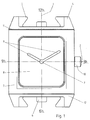
- FIG 1 represents a watch case according to a preferred embodiment of the invention, seen from above.
- the watch case comprises a middle 12 and a container 7.
- the middle 12 comprises two pairs of horns 4 for receiving each a strand of a bracelet (not represented in figure 1).
- the pairs of horns 4 are preferably situated at six o'clock and at twelve o'clock such that the bracelet is attached parallel to the longitudinal axis 1. Other positions are however possible, thus resulting in different alignments of the bracelet relative to the watch case.
- a part of the inner sides of the horns 4 is parallel to the axis 1, whilst the other part 5 has a dovetail shape. This implies that the extremitiesof the bracelet's two strands that will lodge in-between the horns 4 will have the counter-shape of this space, in particular as regards part 5.
- each tongue 6 is a protuberance united with a sliding part of the watch, for example to a part called container 7 which comprises the usual elements of a time-keeper.
- container 7 which comprises the usual elements of a time-keeper.
- the glass 8, hands 9 and crown 10 are visible.
- the double line symbolizes the sliding zone between the middle 12 comprising the horns 4, and the container 7.
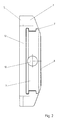
- Figure 2 is a profile at three o'clock of the watch case of figure 1. This view clearly shows the container 7 and the middle 12, separated by the sliding zone 11. It also shows the dovetail part 5 of the horn 4, located on its lower part.
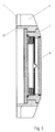
- Figure 3 is a profile at six o'clock of the watch case of figure 1. It shows in particular one of the tongues 6 and a hollow 13 in the middle 12 that allows the tongue 6 to be displaced along the transverse axis when the container is slid relative to the middle 12.
- FIGS 4, 5 and 6 show one view and two cross sections of the different elements already described here above.
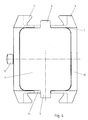
- Figure 4 illustrates the watch case of figure 1 seen from below in locked position.
- the container 7 is preferably centered relative to the middle 12.
- the tongues 6 are preferably at an equal distance of each horn 4 of the corresponding pair.
- the middle 12 is opened in its center and the container 7 is visible from the lower side of the watch case.
- the lower side of the container 7 isat least partly transparent, thus allowing the watch movement to be visible from below the watch.
- the middle 12 is closed in its lower part and the container 7 is only accessible from the upper side and two lateral sides of the watch case.
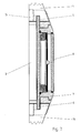
- Figure 7 is a cross section along the six o'clock-twelve o'clock line integrating the two strands of the bracelet 14. It shows the two tongues 6 locking the strands of the bracelet 14 along the vertical axis 3.
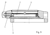
- Figure 8 illustrates the displacement of the container 7 and of the tongues 6 in opened position. As indicated in figure 9, this open position is characterized by the fact that the container 7 has been displaced transversally along the transverse axis 2. In this position, the bracelet's strands can be removed and replaced by others.
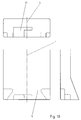
- Figure 10 is three views from different angles of a bracelet strand's extremity according to a preferred embodiment of the invention. It shows that the strand's extremity is for example reinforced by an insert 16, rigid, that moulds itself to fit the shape of the space in-between a pair of horns of the middle.
- an insert 16 rigid, that moulds itself to fit the shape of the space in-between a pair of horns of the middle.
- a recess 17 In the side of the insert 16, parallel to the axis 3, is a recess 17 in which the tongue is set when the strand isput in place and locked.
- the transversal displacement of the container 7 when it is juxtaposed over the middle 12 ensures the locking of the bracelet's two strands along the vertical axis.
- the container 7 is preferably held in this locked position by a holding device , not represented on the figures.
- the holding device includesfor example a ball bearing mounted on springsor a ratchet, or any other mechanism in order to maintain the position of the
- the upper partsof the horns 4 have parallel inner sides and participate to the aesthetic aspect of the watch when a bracelet is fastened to the case, whilst the lower parts of their inner sides form a narrowing in a dovetail shape and are preferably at least partly covered by the bracelet when the latter is fastened to the watch case.
- the horns 4 are possible within the framework of the invention.
- the upper parts of the horns form a narrowing close to the end of the horns whilst the inner sidesof their lower part are parallel to the longitudinal axis.
- the narrowing is then for example visible from the upper side of the watch when the bracelet isfastened to the case and thus possibly contributesto the aesthetic aspect of the watch.
- the narrowing is formed over the entire height of the horns. It is then for example visible from the upper side and from the lower side of the watch when the bracelet is fastened to the case.
- both pairsof horns 4 and both tongues 6 are identical to each other. It ishowever possible, within the framework of the invention, to conceive a watch case or a jewel having two pairs of horns of different shapes. This further brings the advantage that both bracelet strands have differently shaped extremities, thus preventing them from being fastened to the wrong place. It is also possible to imagine a watch case or a jewel having only one pair of horns according to the invention and possibly one other pair of horns of a conventional type, such that for example only one strand of the bracelet can be changed by the user himself.
- the spacing delimited by two horns 4 of a same pair defines a lodging for the extremity of a bracelet strand 14.
- the width of the strand's extremity isapproximately equal to the distance between the inner sidesof the horns 4, such that, when placed in its lodging, the strand 14 is held in both directions along a first axis, for example along the transverse axis 2.
- the horns 4 of a same pair further form a narrowing on at least part of the horns' height, preferably close to the extremity of the horns 4.
- the strand's extremity is preferably rigid and formed to comply with this narrowing, such that the strand is held along a second axis, for example along the longitudinal axis 2, when it is correctly placed in the lodging.
- the narrowing isin the shape of a dovetail.
- Other forms are however possible within the framework of the invention.
- the parts of the horns protruding within the lodging for holding the bracelet's strand in one or preferably both directions along the second axis can for example have circular, rectangular, triangular or any other shapes.
- the corresponding tongue 6 holds the strand in both directions along a third axis, for example along the vertical axis 3, through insertion in a corresponding recess 17 in the preferably rigid strand's extremity (figure 7).
- the tongues 6 are united with the container 7 containing the elements of the time-keeper such as for example the watch movement, the hands, etc.
- the tongues 6 are not united with a container 7, but with another mobile element located for example under and/or inside the middle 12. The mobile element can then be accessed and actuated for example from the lower side and/or from a lateral side of the watch case.
- both tongues are united with the same mobile element. It is however possible, within the framework of the invention, to unite each tongue 6 with a different mobile element, such that each strand can for example be locked or unlocked independently.
- the elements of the time-keeper such as the watch movement, the hands, etc., can then be integrated directly within the middle 12 and do not need to be placed in a mobile container such as the illustrated container 7.
- the first link has the shape and the elements allowing it to be set in the space or lodging in-between the horns of the watch case and to be fastened there according to the same principles of those described here above.
- the invention is not limited to use of bracelet strands with rigid insertsor of metallic bracelets. It is enough for the part of the strands placed in the space in-between the horns of the middle 12 to be sufficiently rigid to be held by the horns' or protuberances' narrowing at their extremities, despite a considerable traction being exerted on the strands.
- the invention isdescribed above in its application to a watch, in particular to a wrist watch.
- the bracelet fastening device of the invention can however also be applied to a jewel, whereas the horns are united with a base element of a part of the jewel whilst the tongue or tongues are united with a mobile element which isattached to the base element and can slide relative to it.
Landscapes
- Physics & Mathematics (AREA)
- General Physics & Mathematics (AREA)
- Adornments (AREA)
- Buckles (AREA)
Abstract
Description
Claims (20)
- Bracelet fastening device for watches and jewels allowing the user to change the bracelet himself, without tool and fully reliably, characterized in that the watch or jewel has at least two horns (4) or protuberances that are not parallel since they are constituted by an opening in the watch or jewel that can be in different shapes, for example in dovetail shape, as long assaid opening displays a narrowing at the extremity of the horns (4) or protuberances and is placed on at least one part of the thickness of the watch or jewel, and in that the extremity of a bracelet strand (14) or metallic bracelet corresponding to said opening has a similar shape, so asto be positioned in this opening and becoming firmly united with the watch or jewel along a longitudinal axis (1) and a transverse axis (2),whilst the locking of the bracelet strand (14) along the vertical axis (3) isensured by at least one tongue (6) introduced in at least one hollow (17) of the bracelet strand, said tongue (6) being placed in this position following an action on a sliding part of the watch or jewel.
- Bracelet fastening device for watches and jewels according to claim 1, characterized in that the watch or jewel is constituted of a middle (12) comprising horns(4) and a container (7) including the usual elements of a time-keeper, and in that the opening designed to receive the extremity of the bracelet strand (14) is made in the middle (12) of the watch or jewel, said middle further having at least one hollow (13) for allowing the tongue (6) to pass and in that the container (7) constitutes the sliding part of the watch or jewel, which is united with the tongue (6).
- Bracelet fastening device for watches and jewels according to the claim 1 or 2, characterized in that the opening is made through the entire thickness of the watch or middle (12).
- Bracelet fastening device for watches and jewels according to the claim 1 or 2, characterized in that the opening is made from above or below the watch or the middle (12) and on one part only.
- Bracelet fastening device for watches and jewels according to the claim 1 or 2, characterized in that the opening is made from below the watch or middle (12) and on one part only, whilst the rest of the width is open so that the space in-between the horns, visible from above, is parallel.
- Bracelet fastening device for watches and jewels according to one of the claims 2 to 5, characterized in that the bracelet strand (14) can be put in place when the container (7) has been displaced transversally relative to the middle (12), said bracelet strand (14) being locked when the container (7) is replaced in its initial position, namely juxtaposed over the middle (12), further in that the container is held in this position by a holding element, for example a ball bearing mounted on a spring or a ratchet.
- Bracelet fastening device for watches and jewels according to one of the claims 1 to 6, characterized in that the extremity of the bracelet strand is reinforced by an insert (16), rigid, on the side of which is located the recess (17) where the tongue (6) is placed when the bracelet strand (14) isput in place.
- Bracelet fastening device for watches and jewels according to one of the claims 1 to 7, characterized in that the bracelet strand (14) containing the clasp, due to the shape of its extremity, can be fastened only at the twelve o'clock position of the watch or jewel.
- Bracelet fastening device for watches and jewels according to one of the claims 1 to 8, characterized in that the bracelet strand, due to the shape of its extremity, cannot be mounted incorrectly.
- Watch case or part of jewel comprising:at least two cooperating protruding portions (4) for limiting the displacement of a bracelet strand (14) along a longitudinal axis (1) of said bracelet strand (14) and a transverse axis (2) of said bracelet strand (14),a mobile element (7) which can be slid along an axis (2) relative to said at least two cooperating protruding portions (4) between a locked position and an unlocked position so asto limit the displacement of said bracelet strand (14) along a vertical axis (3) of said bracelet strand (14) in said locked position, and to allow the changing of said bracelet strand (14) in said unlocked position.
- Watch case or part of jewel according to claim 10, said at least two cooperating protruding portions comprising at least two horns(4) united with a base element (12), said at least two horns (4) having a narrowing (5) at their end on at least a part of their thickness,
said mobile element (7) being attached to said base element (12) such that it can be slid along an axis (2) relative to said base element (12) between said locked position and said unlocked position. - Watch case or part of jewel according to claim 11, said narrowing (5) having a dovetail shape.
- Watch case or part of jewel according to one of the claims 10 to 12, said mobile element (7) comprising a tongue (6) introduced in a recess(17) in said bracelet strand (14) when in said locked position.
- Watch case or part of jewel according to claim 13, said tongue (6) being placed between said at least two cooperating protruding portions (4) in said locked position.
- Bracelet strand (14) comprising an extremity with a recess (17), said recess (17) being at least partly closed on two opposite sides such that a tongue (6) which would be introduced in said recess(17) would be held in both directions along an axis (3) perpendicular to said opposite sides.
- Bracelet strand (14) according to claim 15, said extremity being rigid.
- Bracelet strand (14) according to claim 16, said extremity being a rigid insert within said strand (14).
- Watch or jewel, comprising:a watch case or part of jewel,a bracelet strand (14) attached to said watch case or part of jewel,said watch case or part of jewel comprising at least two cooperating protruding portions (5) for limiting displacement of said bracelet strand (14) along a longitudinal axis(1) of said bracelet strand (14) and a transverse axis (2) of said bracelet strand (14), and a mobile element (7) which can be slid along an axis (2) relative to said at least two cooperating protruding portions (5) between a locked position and an unlocked position so asto limit the displacement of said bracelet strand (14) along a vertical axis (3) of said bracelet strand (14) in said locked position, and to allow the changing of said bracelet strand (14) in said unlocked position.
- Watch or jewel according to claim 18, said mobile element (7) comprising a tongue (6), an extremity of said bracelet strand (14) comprising a recess (17) at least partly closed on two opposite sides, said tongue (6) being inserted in said recess(17) in said locked position, such that said tongue (6) is held in both directions along an axis(3) perpendicular to said opposite sides.
- Watch or jewel according to claim 19, said axis perpendicular to said opposite sides being parallel to said vertical axis (3).
Priority Applications (1)
| Application Number | Priority Date | Filing Date | Title |
|---|---|---|---|
| EP05109554A EP1655643A1 (en) | 2004-11-09 | 2005-10-13 | Bracelet fastening device for watches and jewels |
Applications Claiming Priority (2)
| Application Number | Priority Date | Filing Date | Title |
|---|---|---|---|
| CH43042004 | 2004-01-13 | ||
| CH00043/04A CH697577B1 (en) | 2004-01-13 | 2004-01-13 | strap fastening device for watches and jewelery. |
Publications (2)
| Publication Number | Publication Date |
|---|---|
| EP1563754A2 true EP1563754A2 (en) | 2005-08-17 |
| EP1563754A3 EP1563754A3 (en) | 2006-11-02 |
Family
ID=34716060
Family Applications (1)
| Application Number | Title | Priority Date | Filing Date |
|---|---|---|---|
| EP05100033A Withdrawn EP1563754A3 (en) | 2004-01-13 | 2005-01-04 | Bracelet fastening device for watches and jewelry |
Country Status (4)
| Country | Link |
|---|---|
| US (1) | US20050152227A1 (en) |
| EP (1) | EP1563754A3 (en) |
| CN (1) | CN1640341A (en) |
| CH (1) | CH697577B1 (en) |
Families Citing this family (6)
| Publication number | Priority date | Publication date | Assignee | Title |
|---|---|---|---|---|
| US8432687B2 (en) * | 2011-02-23 | 2013-04-30 | Cole Patrick Schneider | Answer bracelet |
| US8705234B2 (en) * | 2011-02-23 | 2014-04-22 | Cole Patrick Schneider | Answer bracelet |
| JP1546263S (en) * | 2015-03-06 | 2016-03-22 | ||
| EP3473127B1 (en) * | 2017-10-20 | 2021-10-06 | Montres Breguet S.A. | Fixing device for a bracelet |
| EP3474084A1 (en) * | 2017-10-20 | 2019-04-24 | Montres Breguet S.A. | Fixing device for a bracelet |
| EP3674815B1 (en) * | 2018-12-27 | 2021-09-29 | Omega SA | Watch case provided with an annular ring and wristwatch and kit for assembling a wristwatch comprising same |
Family Cites Families (6)
| Publication number | Priority date | Publication date | Assignee | Title |
|---|---|---|---|---|
| FR709518A (en) * | 1931-01-15 | 1931-08-07 | Cartier | Bracelet or necklace or chain clasp, particularly applicable to watch bracelets |
| CH216721A (en) * | 1938-12-19 | 1941-09-15 | Georges Meyer Sa D Ets | Wrist watch. |
| GB1426346A (en) * | 1972-11-13 | 1976-02-25 | Suisse Pour Lindustrie Horloge | Clasp fastener for fastening togehter two elements |
| JPS5955012U (en) * | 1982-10-01 | 1984-04-11 | シチズン時計株式会社 | Watch case and band attachment device |
| CH679902B5 (en) * | 1990-06-07 | 1992-11-13 | Bratec Baumgartner & Brancaleo | |
| FI119094B (en) * | 2003-11-20 | 2008-07-15 | Polar Electro Oy | Portable personal electronic device that can be attached to the wrist |
-
2004
- 2004-01-13 CH CH00043/04A patent/CH697577B1/en not_active IP Right Cessation
-
2005
- 2005-01-04 EP EP05100033A patent/EP1563754A3/en not_active Withdrawn
- 2005-01-11 US US11/032,927 patent/US20050152227A1/en not_active Abandoned
- 2005-01-12 CN CN200510004482.9A patent/CN1640341A/en active Pending
Also Published As
| Publication number | Publication date |
|---|---|
| US20050152227A1 (en) | 2005-07-14 |
| CN1640341A (en) | 2005-07-20 |
| EP1563754A3 (en) | 2006-11-02 |
| CH697577B1 (en) | 2008-12-15 |
Similar Documents
| Publication | Publication Date | Title |
|---|---|---|
| US6738317B2 (en) | Wristwatch with a reversible case | |
| US9883722B2 (en) | Wristwatch comprising a clasp connected to the case | |
| CN100559306C (en) | Timepieces with interchangeable bezels | |
| US5158219A (en) | Watch-case | |
| US11022943B2 (en) | Device for attaching a bracelet | |
| US20180011448A1 (en) | Watch and item of jewellery with interchangeable wristband | |
| US20080310260A1 (en) | Modular watch and device for securing a watch strap to a watch casing | |
| CN102667642B (en) | Case for a timepiece having multiple configurations | |
| US20070253290A1 (en) | Modular wristwatch | |
| US9314073B2 (en) | Adjustable bracelet clasp | |
| US11782390B2 (en) | Watch case equipped with an exterior element | |
| KR102313926B1 (en) | Watch case provided with an annular ring, and a wristwatch and a wristwatch assembly kit comprising the same | |
| JP2017094093A5 (en) | ||
| US20060114752A1 (en) | Bracelet fastening device for watches and jewels | |
| US10895846B2 (en) | Reversible wristwatch with multiple configurations | |
| JP3281425B2 (en) | Clock side | |
| EP1563754A2 (en) | Bracelet fastening device for watches and jewelry | |
| US8770831B1 (en) | Coupling pin connection for securing a watchband to a watchcase | |
| EP1655643A1 (en) | Bracelet fastening device for watches and jewels | |
| US3964250A (en) | Wristwatch case | |
| HK40069260B (en) | Watch case equipped with an exterior element | |
| JP2004283356A (en) | Inner clasp for accessories, accessories and clock | |
| HK1080696A (en) | Bracelet fastening device for watches and jewelry | |
| JP4306285B2 (en) | Trinkets for jewelry, jewelry and watches | |
| HK40069260A (en) | Watch case equipped with an exterior element |
Legal Events
| Date | Code | Title | Description |
|---|---|---|---|
| PUAI | Public reference made under article 153(3) epc to a published international application that has entered the european phase |
Free format text: ORIGINAL CODE: 0009012 |
|
| AK | Designated contracting states |
Kind code of ref document: A2 Designated state(s): AT BE BG CH CY CZ DE DK EE ES FI FR GB GR HU IE IS IT LI LT LU MC NL PL PT RO SE SI SK TR |
|
| AX | Request for extension of the european patent |
Extension state: AL BA HR LV MK YU |
|
| PUAL | Search report despatched |
Free format text: ORIGINAL CODE: 0009013 |
|
| AK | Designated contracting states |
Kind code of ref document: A3 Designated state(s): AT BE BG CH CY CZ DE DK EE ES FI FR GB GR HU IE IS IT LI LT LU MC NL PL PT RO SE SI SK TR |
|
| AX | Request for extension of the european patent |
Extension state: AL BA HR LV MK YU |
|
| 17P | Request for examination filed |
Effective date: 20070314 |
|
| AKX | Designation fees paid |
Designated state(s): AT BE BG CH CY CZ DE DK EE ES FI FR GB GR HU IE IS IT LI LT LU MC NL PL PT RO SE SI SK TR |
|
| 17Q | First examination report despatched |
Effective date: 20070703 |
|
| STAA | Information on the status of an ep patent application or granted ep patent |
Free format text: STATUS: THE APPLICATION IS DEEMED TO BE WITHDRAWN |
|
| 18D | Application deemed to be withdrawn |
Effective date: 20071114 |