EP1563252B1 - Positional measurement of a feature within an image and monitoring an aircraft structure - Google Patents
Positional measurement of a feature within an image and monitoring an aircraft structure Download PDFInfo
- Publication number
- EP1563252B1 EP1563252B1 EP03769646.5A EP03769646A EP1563252B1 EP 1563252 B1 EP1563252 B1 EP 1563252B1 EP 03769646 A EP03769646 A EP 03769646A EP 1563252 B1 EP1563252 B1 EP 1563252B1
- Authority
- EP
- European Patent Office
- Prior art keywords
- image
- feature
- coordinates
- image capture
- determining
- Prior art date
- Legal status (The legal status is an assumption and is not a legal conclusion. Google has not performed a legal analysis and makes no representation as to the accuracy of the status listed.)
- Expired - Lifetime
Links
Images



Classifications
-
- G—PHYSICS
- G06—COMPUTING OR CALCULATING; COUNTING
- G06T—IMAGE DATA PROCESSING OR GENERATION, IN GENERAL
- G06T7/00—Image analysis
- G06T7/20—Analysis of motion
-
- G—PHYSICS
- G06—COMPUTING OR CALCULATING; COUNTING
- G06T—IMAGE DATA PROCESSING OR GENERATION, IN GENERAL
- G06T7/00—Image analysis
- G06T7/70—Determining position or orientation of objects or cameras
- G06T7/73—Determining position or orientation of objects or cameras using feature-based methods
- G06T7/74—Determining position or orientation of objects or cameras using feature-based methods involving reference images or patches
-
- G—PHYSICS
- G06—COMPUTING OR CALCULATING; COUNTING
- G06V—IMAGE OR VIDEO RECOGNITION OR UNDERSTANDING
- G06V10/00—Arrangements for image or video recognition or understanding
- G06V10/20—Image preprocessing
- G06V10/24—Aligning, centring, orientation detection or correction of the image
- G06V10/245—Aligning, centring, orientation detection or correction of the image by locating a pattern; Special marks for positioning
Definitions
- the present invention relates to a method of determining the position of a feature within an image, a method of measuring dimensional changes in an object utilising that method and apparatus for carrying out the methods, as well as a method and apparatus for monitoring an aircraft structure.
- extensometry The measurement of strains in such mechanical tests is termed extensometry and has traditionally been carried out by mechanical or electromechanical instruments termed extensometers, or by the use of strain gauges.
- Other equipment such as dial gauges or linear variable differential transformers (LVDTs) are traditionally used for the measurement of displacements in such mechanical tests, whilst accelerometers are used in the monitoring of large structures.
- LVDTs linear variable differential transformers
- accelerometers are used in the monitoring of large structures.
- mechanical or electromechanical instruments suffer from various disadvantages, including the requirements to place one or more parts of the equipment, or sensors, in direct contact with the object being monitored or tested. This is not practical for some fragile or small structures.
- each extensometer or strain gauge can only monitor a discrete point of the object under test and it is therefore necessary to use a large number of extensometers or strain gauges if it is desired to monitor the whole of, or a large area of, the object under test.
- the use of such mechanical or electromechanical instruments in certain environments is not practical, for example in extremely hot and in particular extremely cold environments, or environments having chemically corrosive atmospheres.
- Prior art systems are known that utilise captured video images for the measurement of distances between simple features such as lines or circles of a known geometry, the lines or circles often being physically attached to the object being monitored prior to the commencement of monitoring.
- the requirement to add such known geometrical features, or targets, to the object under test limits the minimum size of object that can be monitored using such prior art video monitoring systems.
- Aircraft are designed to have a specific life under the various loadings that apply to them under operational conditions. Three separate lifetimes may be ascribed to an airframe; calendar age, flight cycles and flight hours, each relating to a different set of degradation mechanisms. Individual aircraft may then have very different mixes of the three measures of age. For instance, a commercial aircraft used on short haul routes will accumulate flight cycles far faster than an identical aircraft used on long haul routes, which may be accumulating flight hours at a much greater rate. Both limiting cases must be accounted for in the design process and maintenance schedules developed for the aircraft.
- a method of determining the coordinates of a feature within an image comprising a plurality of pixels, the method comprising: determining an estimate of the coordinates of the feature to within a fraction of a pixel; translating the feature relative to the pixels such that the sum of the pixel fraction of the initial estimated coordinates and the pixel translation is an integer value; determining a further estimate of the coordinates of the translated feature within the image to within a fraction of a pixel; and determining a refined estimate of the feature coordinates by summing the pixel fraction of the previous estimate of the coordinates with the further estimate of coordinates.
- a method according to this first aspect is defined in independent claim 1 and dependent claims 2 to 7.
- the first and second determining steps comprise correlating the image feature and image using a predetermined correlation function to determine the position of the feature within the image to the nearest pixel, evaluating the correlation function at a plurality of pixel positions in the neighbourhood of the determined position and fitting the plurality of values to a further function and differentiating the further function to determine its turning point, whereby the position corresponding to the determined turning point provides the position of the feature to within the fraction of the pixel.
- the correlation function may be evaluated at a plurality of sub-pixel positions.
- the sub-pixel positions may be in closer proximity to the determined position than the pixel positions.
- the method may further comprise determining the coordinates of the feature within a further image, the position of the further image being known relative to the first image; determining the difference in position of the feature between the first and further image; superimposing said first and further image such that said feature is substantially in registration, and applying a Super Resolution technique to said superimposed images, whereby an increased resolution representation of said feature is produced.
- the translating step, second determining step and summing step are repeated at least once.
- a method of measuring dimensional changes in a sample comprising: capturing at least two images of the sample, each image being captured at a different time with respect to one another; determining the coordinates of a feature within each image utilising the method of any one of claims 1 to 7; and comparing the determined coordinates of the feature to determine any dimensional changes in the sample.
- positioning apparatus for determining the coordinates of a feature, the apparatus comprising: an image capture device arranged to provide an image encompassing the feature, the image comprising a plurality of pixels; and an image processor arranged to receive the captured image and determine the coordinates of the feature by executing the method steps of any one of claims 1 to 7.
- the positioning apparatus further comprises a monitor arranged to receive and display the captured image and feature selection means arranged to select a feature within the displayed image and identify the selected feature to the image processor.
- measurement apparatus for detecting dimensional changes in a sample, the apparatus comprising: an image capture device arranged to sequentially provide a plurality of images encompassing a feature, each image comprising a plurality of pixels; an image processor arranged to sequentially receive the plurality of captured images and determine the coordinates of the feature from each image by executing the method steps of any one of claims 1 to 7; and a position comparator arranged to compare the determined coordinates of the feature for each image and determine if the determined coordinates change between images.
- a method of determining the 3-dimensional coordinates of a feature comprising: providing at least two image capture devices each arranged to capture an image including the feature; determining the coordinates of each of said image capture devices with respect to one another; determining the coordinates of the feature within each image in accordance with the method of any one of claims 1 to 7, and calculating the 3-dimensional coordinates of the feature given the determined feature coordinates in each image and the determined relative positions of each image capture device.
- a method of measuring 3-dimensional changes in a sample comprising: providing at least two image capture devices at a known spatial relationship to one another; capturing at least two images of the sample with each image capture device, the two images being captured at a different time from one another; determining the 2-dimensional coordinates of a feature within each image in accordance with the method of any one of claims 1 to 7; calculating the 3-dimensional coordinates of the feature from the first and second images from the 2-dimensional coordinates and spatial relationship of the image capture devices; and comparing the 3-dimensional coordinates to determine any dimensional changes in the sample.
- a seventh aspect of the present invention there is also provided a method of monitoring an aircraft structure, the method comprising the steps of attaching one or more image captures devices to a first portion of an aircraft structure, attaching one or more targets to a second portion of the aircraft structure, the or each target being within the field of view of the or each image capture device, capturing a series of images from the or each image capture device and processing the captured images to determine the magnitude and/or direction of movement of the or each target, wherein the processing step comprises determining the coordinates of the or each target in each frame of the series of frames according to the method of claim 1.
- Metrology techniques based on the acquisition and manipulation of video data streams are thus used to monitor the relative displacements of different parts of an aircraft structure to a high degree of accuracy. From the data on the displacements, the deformation of the aircraft structures can be deduced and the major loadings on the airframe can be monitored. These loadings can then be summed over time, for example, to indicate the rate at which the fatigue life of the airframe is being used. Additionally, comparison of the deformation in different structures can provide information on the structural condition of the aircraft. For example, monitoring wing and fuselage deformations provides information on the fuselage's response to the wing loadings.
- the method comprises attaching at least three targets to the second portion of the aircraft structure at known relative positions to the second portion of the aircraft, the at least three targets being within the field of view of the or each image capture device, whereby the position and orientation of said second portion of the aircraft relative to the or each image capture device is determined by said processing step.
- At least one further target may be provided mounted orthogonally offset from the plane of the other targets within the same field of view of an image capture device. This has the advantage of magnifying the movement of the further target due to bending of the aircraft structure to which it is attached.
- a reflective surface such as a mirror, may be attached to the aircraft structure such that at least one of the targets is within the field of view of an image capture device when viewed through the mirror.
- Each image capture device may be arranged to automatically identify the targets as items of interest. This allows a target to be automatically reacquired should it be momentarily obscured from the view of the image capture device.
- an aircraft structure monitoring apparatus comprising: at least one image capture device arranged to be attached to a first portion of an aircraft structure; at least one target arranged to be attached to a second portion of the aircraft structure, whereby the at least one target is within the field of view of the at least one image capture device; and an image processor arranged to receive a plurality of images from the at least one image capture device and process said received images to determine the magnitude and/or direction of movement of the at least one target by determining the coordinates of the target in each image according to the method of claim 1.
- the target may be in the form of an illuminated panel that includes areas of differential illumination.
- the illumination may be provided by LED's or other similarly reliable light sources. Such targets minimise the influence of ambient light levels on the accuracy of the monitoring apparatus.
- a flexible light guide may interconnect the image capture device and target.
- the light guide may be a sealed, flexible tube or other suitable means provided to act as a shroud to prevent people and/or other objects from obscuring the targets from the camera and to reduce or eliminate the effects of changes in ambient lighting.
- FIGS 1a to 1c schematically illustrate a prior art method of determining the (X,Y) position of a feature within an image.
- a video image of the required scene is captured using a conventional CCD (charge coupled device) camera and converted to a data stream that a computer can manipulate via a frame grabber.
- bounding regions are drawn around those features of the image that the user wishes to monitor the position of.
- Suitable software captures the pattern associated with those features and outputs an (X,Y) position corresponding to the position of each feature.
- the illustrated prior art method for the identification of the position of features in a video stream of no fixed geometry is known as template matching.
- NGC Normalised Greyscale Correlation
- Greyscale correlation a correlation function to measure the degree of the similarity between two images, or parts of images.
- Standard correlation functions used include Normalised Greyscale Correlation (NGC), Greyscale correlation and Euclidean distance.
- NGC Normalised Greyscale Correlation
- Greyscale correlation a correlation function to measure the degree of the similarity between two images, or parts of images.
- NGC Normalised Greyscale Correlation
- Greyscale correlation Greyscale correlation
- Euclidean distance Euclidean distance
- the correlation function is used to find the region of an image that best matches the feature captured by the bounding region.
- the correlation function returns a score of how well the feature captured by the bounding region matches the underlying image when the feature captured by the bounding region is at a position (X, Y) in the image.
- the correlation function is evaluated at a number of (X, Y) positions in the image to determine the position that gives the best value of the correlation function. This yields the (X, Y) position of the feature within the image to the nearest pixel.
- Figures 1a to 1c schematically represent a pixel with 4, 8 and 24 nearest neighbours respectively.
- each small square 2 represents an individual pixel, with the central, shaded square 4 representing the position of the feature of interest, to the nearest pixel.
- the neighbouring pixels at which the correlation function is evaluated, are indicated by the squares having black dots in them 6.
- the values of the correlation function at the N surrounding pixels are fitted to a function, such as a bi-quadratic, typically using a least-squares fitting technique.
- the sub-pixel position of the feature may then be estimated by differentiating the quadratic and calculating the position of its turning point since the maximum fit will occur at a turning point in the differentiated quadratic.
- the number N of surrounding pixels is chosen to ensure that N is at least equal or greater than the number of free parameters in the selected function, so that the function can be solved.
- each individual square represents a single pixel, with the reference feature of an image represented by the filled boxes 8.
- each pixel may have a specific greyscale value anywhere between, and including, black and white.
- the feature is composed initially of a series of pixels of the same greyscale, either black or white.
- the pattern of the comparison and reference images will be an exact match. However, if the comparison image has moved a non-integer number of pixels then the pattern will be as seen in Figure 2b .
- the pattern is now bounded by pixels 10 in which the greyscale value is between black and white as represented by the cross-hatching, and the pattern is clearly visually distinct from that of the reference feature. This effect is known as aliasing.
- Embodiments of the present invention utilise the NGC approach to gain an initial estimate of the position of the reference feature of interest. However, two additional operations are performed to both eliminate the systematic error and refine the best estimate of the position of the reference feature of interest to give the maximum resolution.
- the standard NGC technique is used to calculate an initial estimate of the sub-pixel position of the feature.
- the feature is then resampled by projecting the pixel array onto a new pixel array that has been shifted by a fractional part of a pixel, such that the sum of the pixel translation and the fractional part of the estimated sub-pixel position is an integer value. That is to say if the position estimate is (x1 ⁇ 2, y1 ⁇ 4) the pixel array may be shifted by -1 ⁇ 2 a pixel in the X direction and -1 ⁇ 4 a pixel in the Y direction.
- the pixel array may be shifted by +1 ⁇ 2 a pixel in the X direction and +3 ⁇ 4 a pixel in the Y direction.
- direction of translation would be such so as to minimise the magnitude of the translation.
- the entire image may alternatively be translated. This is illustrated in Figure 4 .
- the solid grid 16 represents the initial pixel array, whilst the broken grid 18 represents the new pixel array that has been shifted by the fractional part of the current sub-pixel position estimate.
- the fractional part of the sub-pixel position estimate (e.g. half a pixel) is represented by dx, dy as shown in Figure 4 .
- each pixel has either a greyscale value closer to black or white or where the greyscale value was already black or white it remains so.
- the correlation function is then re-evaluated at the best matched position and its N surrounding neighbours and the sub-pixel position recalculated, using the standard NGC technique.
- the fractional part (dx, dy) of the original sub-pixel position estimate is added to the re-evaluated best matched position to give a refined sub-pixel estimate. This procedure may be iterated a number of times to further refine the sub-pixel estimate.
- a further improvement in accuracy is achieved by taking the N neighbouring samples of the correlation function at sub-pixel positions.
- pixel interpolation recalculated pixel values may be derived and the correlation function may be evaluated at any real valued co-ordinate. This is schematically illustrated in Figures 5a to 5c in which the 4, 8 and 24 respective neighbouring sampled points 20 are at sub-pixel positions.
- the bi-quadratic to which the values of the correlation function evaluated at the N surrounding positions is fitted may better approximate the true correlation surface near its peak value if the N neighbours are chosen to be close to the peak. This leads to an improvement in accuracy if the N neighbours are chosen to be close to the position of the best matched pixel.
- Super Resolution techniques As will be known to the skilled man, these techniques create a single, high resolution image from two or more similar images. The plurality of images are aligned in complete registration to sub-pixel accuracy. The information present in the aligned images is then combined using any known Super Resolution technique, to produce a single, high resolution image, (i.e. more pixels than any of the originals).
- Super Resolution is applied here to generate a high resolution representation of the feature.
- Multiple images containing the feature are available and using the techniques described above the position of the feature is known within each image to sub-pixel accuracy. The images can therefore be aligned such that the feature appears in complete registration throughout the image set. A high resolution version of the feature can then be calculated.
- the high resolution representation of the feature also enables the feature translation used in refining the initial estimate of the position of a feature to be accomplished to a higher accuracy.
- FIG. 6 schematically shows video metrology equipment constituting an embodiment of the present invention.
- a test sample 22 having a visual target 24 marked thereon is placed in a test machine 26.
- the test machine is arranged to apply a slowly increasing tensile load to the test sample 22.
- a video camera 28 is arranged to monitor the test sample 22 at the target location 24 and provides video data 30 to a processor 32.
- the processor also receives sample load data from the test machine.
- the processor is arranged to implement the method of the present invention as described hereinabove.
- a monitor 34 is coupled to the processor 32 and is arranged to show the captured video image, or results of the image processing performed by the processor.
- the processor 32 includes a comparator for comparing the determined position of an object or feature from a sequence images received from the video camera 28.
- the compared positions allow any dimensional changes, such as stretching or deflection, of the test sample 22 to be identified and measured very accurately.
- the sequence of images received from the video camera 28 may be each video frame, or may be more widely separated in time as is appropriate.
- a feature selector may also be included within the equipment to allow manual or automatic selection of an object or feature within an image to be made.
- the feature selector may, for example, comprise circuitry arranged to generate a bounding region superimposed on the image displayed on the monitor 34, the position of the bounding box being controllable by a user, or may utilise image recognition technology to select a feature.
- An object or feature of interest is thus enclosed by the bounding box and identified to the image processor 32 as the object the position of which is to be determined.
- the video capture and analysis apparatus may equally be used as a simple positioning system, the position of an object being determinable to a high level of accuracy. This has applications in precise 'pick and place' operations, such as within integrated circuit manufacture.
- This invention offers a substantial improvement in resolution compared to the video metrology approaches of the prior art and gives results that are equivalent to those obtained by conventional extensometers or strain gauges. Furthermore, the invention is not limited to specific high contrasts target geometries and can utilise the natural markings on samples, thus avoiding problems with applying targets. This freedom of target geometry and contrast allows very small samples to be tested, permitting full advantage to be taken of the scale insensitivity inherent in video metrology.
- An application of video metrology is in the monitoring of deformations in the main fuselage, or other structural elements, of an aircraft.
- An example of a suitable arrangement of apparatus is shown in Figure 7 .
- a camera 40 or cameras is rigidly attached to a fixed point 42 or points on the aircraft structure 44 and trained along the fuselage to image a set of targets 46 some distance away, also rigidly attached to the aircraft structure.
- the camera 40 and targets 46 could be within the aircraft cabin(s) or cargo hold(s), or be mounted externally. In one embodiment two targets 46', 46" are to be used.
- the image of the two targets are provided by the camera 40 to a suitable computer and are captured by appropriate software and their position in subsequent frames tracked using algorithms such as, but not exclusively, grey scale normalised correlation.
- the particularly suitable robust and high accuracy video gauging approach described herein may be used but any suitable position tracking technique could also be utilised.
- the position of the targets in pixels is constantly determined by the computer and converted into real dimensions.
- FIGs 8a to 8e Each possible deflection of the imaged targets is shown separately in Figures 8a to 8d and combined in Figure 8e.
- Figures 8b and 8c respectively show the target deflections that would be caused by vertical and horizontal shear or bending of the fuselage.
- Figure 8d shows the target deflection caused by torsion, or twisting, of the fuselage.
- Figures 9a and 9b show the difference between shear and bending and illustrates how these two deformation modes can be separated.
- Figure 9a shows pure shear. In this case the vertical lines 50 and 52 remain parallel and the apparent distance between the two targets 46' and 46" remains unchanged.
- Figure 9b shows pure bending. In this case the vertical lines 50, 52 are no longer parallel, so the distance between the two targets changes.
- An alternative way of separating out shear and bending deformations is to mount an additional target 60 at a known relative position to the camera 40 but view it in a mirror 62 mounted in the same plane as the target 46 as shown in Figure 11 .
- the image of the additional target 60 in the mirror would only appear to move with a bending deformation and would be completely insensitive to pure shear or torsional deformations.
- the monitoring software may include automatic target detection functions to reacquire targets lost, for example, by momentary obscuration by passengers or flight crew.
- a greater number of targets than two would be of benefit in terms of providing redundant data channels, and of limiting obscuration issues.
- two cameras may be placed back to back in fixed register with each other at the mid point of the fuselage, or cabin, with targets at each end of the fuselage, or cabin, to provide an unambiguous picture of the totality of the deflections in the cabin.
- a particularly suitable form of target and target carrier is an illuminated panel upon which the targets are marked as areas of differential illumination. LEDs or similar high reliability light sources can be utilised. Such targets would minimise any influence of the level of cabin illumination on the accuracy of the monitoring function.
- each cabin may be monitored individually or the optimum cabin for monitoring may be identified by an examination of the overall structural response of the airframe.
- the cameras and targets may be mounted externally to the fuselage to provide similar data on wing, rudder or tail deflections.
- FIG. 11 An alternative approach is to use a sealed monitoring unit, as also shown in Figure 11 .
- This incorporates the camera(s), targets, light source(s) and mirrors into a sealed but flexible tube 64, which can be mounted, for example, between fuselage frames in the cargo bay or between ribs in the wing.
- the tube acts as a shroud to prevent people and/or objects from obscuring the targets from the camera and block out the effects of changes in ambient lighting.
- the monitoring function takes place in the image space so that the overall dimensional resolution of this system can be adjusted as required by the use of suitable lenses on the cameras.
- the high accuracy video gauging approach described herein is capable of a proven resolution better than 0.005 pixels for a single target and a conventional, low cost camera will have an image field of more than 500 pixels, giving a resolution of 1 part in 100,000.
- the offset need not be achieved with physical structure, a small LED laser could be used to shine on a translucent screen, with that laser spot being taken as the target. In this case the offset could be as great as required without any difficulties due to the response of the structure utilised to generate the dimensional offset.
- the position of the target can be measured in 3D.
- a single camera is sufficient to measure the 3D position and orientation of an object that has 3 or more targets attached.
- Wing deflections are substantially greater than fuselage deflections.
- the data acquired by the gauging system can be interrogated by an appropriate computer system and events that exceeded a predetermined level or levels logged. In this way the loadings on the specific airframe can be monitored and summed for comparison with models of the design fatigue life of the airframe and structurally safe maintenance or inspection intervals determined. Additionally, any very severe events that fall outside the design envelope can be instantly detected to trigger remedial actions.
Landscapes
- Engineering & Computer Science (AREA)
- Physics & Mathematics (AREA)
- General Physics & Mathematics (AREA)
- Theoretical Computer Science (AREA)
- Multimedia (AREA)
- Computer Vision & Pattern Recognition (AREA)
- Length Measuring Devices By Optical Means (AREA)
- Image Processing (AREA)
Description
- The present invention relates to a method of determining the position of a feature within an image, a method of measuring dimensional changes in an object utilising that method and apparatus for carrying out the methods, as well as a method and apparatus for monitoring an aircraft structure.
- There is often a desire to monitor the strains or displacements in an object when that object is undergoing a mechanical test, or equally the displacements of large structures such as buildings or bridges under applied loads. Such monitoring can be used to determine the maximum mechanical loads that may be safely applied to a particular object, or to ensure that excessive displacements within an object that are likely to cause mechanical failure do not occur or are identified in time to apply corrective measures and thus prevent failure.
- The measurement of strains in such mechanical tests is termed extensometry and has traditionally been carried out by mechanical or electromechanical instruments termed extensometers, or by the use of strain gauges. Other equipment such as dial gauges or linear variable differential transformers (LVDTs) are traditionally used for the measurement of displacements in such mechanical tests, whilst accelerometers are used in the monitoring of large structures. However, such mechanical or electromechanical instruments suffer from various disadvantages, including the requirements to place one or more parts of the equipment, or sensors, in direct contact with the object being monitored or tested. This is not practical for some fragile or small structures. Additionally, each extensometer or strain gauge can only monitor a discrete point of the object under test and it is therefore necessary to use a large number of extensometers or strain gauges if it is desired to monitor the whole of, or a large area of, the object under test. Furthermore, the use of such mechanical or electromechanical instruments in certain environments is not practical, for example in extremely hot and in particular extremely cold environments, or environments having chemically corrosive atmospheres.
- Prior art systems are known that utilise captured video images for the measurement of distances between simple features such as lines or circles of a known geometry, the lines or circles often being physically attached to the object being monitored prior to the commencement of monitoring. The requirement to add such known geometrical features, or targets, to the object under test limits the minimum size of object that can be monitored using such prior art video monitoring systems.
- It is known to determine the coordinates of features in images with sub-pixel accuracy eg. from the documents
EP 0 999 521 A2 ,WO 00/77720 A US 5 850 466 A ,US 5 640 200 A andUS 4 805 123 A . - An area in which it is beneficial to monitor the stresses and strains of a structure is the aerospace industry. Aircraft are designed to have a specific life under the various loadings that apply to them under operational conditions. Three separate lifetimes may be ascribed to an airframe; calendar age, flight cycles and flight hours, each relating to a different set of degradation mechanisms. Individual aircraft may then have very different mixes of the three measures of age. For instance, a commercial aircraft used on short haul routes will accumulate flight cycles far faster than an identical aircraft used on long haul routes, which may be accumulating flight hours at a much greater rate. Both limiting cases must be accounted for in the design process and maintenance schedules developed for the aircraft. These maintenance schedules account for a large proportion of the Direct Operating Costs (DOC) incurred by the operators in order to ensure the safety and integrity of the airframe. Despite these high maintenance costs there have been occasions where structural failure of the airframe has occurred leading to loss of life and great economic costs. The operators seek to reduce DOC and one way of doing this would be to carry out maintenance on the aircraft on an as-required basis rather than to a fixed schedule.
- To achieve this without detriment to safety requires that the aircraft's systems be constantly monitored so that the condition of the aircraft is known at all times. Some major subsystems such as engines, avionics etc., can be so monitored. However, monitoring the airframe's response to flight loads and the condition of the aircraft's structure is more difficult. Efforts have been made to achieve this aim, and several approaches have been proposed. These rely on distributing sensors throughout the structures of interest, recovering data from these sensors and interpreting this data to give information relating to the local and global response of the airframe. Sensors that have been proposed include conventional strain gauges and their optical analogues, such as Bragg gauges, together with accelerometers and other sensors. Whilst these sensors are very effective at reporting local conditions they are less successful at monitoring the totality of the aircraft's structural response. Equally, to use these approaches requires a substantial investment in distributing an adequate array of sensors throughout the structure of the aircraft. This has negative cost implications for this approach and makes it primarily of applicability to future new-build aircraft.
- According to a first aspect of the present invention there is provided a method of determining the coordinates of a feature within an image, the image comprising a plurality of pixels, the method comprising: determining an estimate of the coordinates of the feature to within a fraction of a pixel; translating the feature relative to the pixels such that the sum of the pixel fraction of the initial estimated coordinates and the pixel translation is an integer value; determining a further estimate of the coordinates of the translated feature within the image to within a fraction of a pixel; and determining a refined estimate of the feature coordinates by summing the pixel fraction of the previous estimate of the coordinates with the further estimate of coordinates. A method according to this first aspect is defined in independent claim 1 and
dependent claims 2 to 7. - Preferably, the first and second determining steps comprise correlating the image feature and image using a predetermined correlation function to determine the position of the feature within the image to the nearest pixel, evaluating the correlation function at a plurality of pixel positions in the neighbourhood of the determined position and fitting the plurality of values to a further function and differentiating the further function to determine its turning point, whereby the position corresponding to the determined turning point provides the position of the feature to within the fraction of the pixel.
- Additionally, the correlation function may be evaluated at a plurality of sub-pixel positions.
- Additionally, the sub-pixel positions may be in closer proximity to the determined position than the pixel positions.
- The method may further comprise determining the coordinates of the feature within a further image, the position of the further image being known relative to the first image; determining the difference in position of the feature between the first and further image; superimposing said first and further image such that said feature is substantially in registration, and applying a Super Resolution technique to said superimposed images, whereby an increased resolution representation of said feature is produced.
- Additionally or alternatively, the predetermined correlation function may comprise a normalised greyscale correlation function.
- Preferably, the translating step, second determining step and summing step are repeated at least once.
- According to a second aspect of the present invention there is provided a method of measuring dimensional changes in a sample, the method comprising: capturing at least two images of the sample, each image being captured at a different time with respect to one another; determining the coordinates of a feature within each image utilising the method of any one of claims 1 to 7; and comparing the determined coordinates of the feature to determine any dimensional changes in the sample.
- According to a third aspect of the present invention there is provided positioning apparatus for determining the coordinates of a feature, the apparatus comprising: an image capture device arranged to provide an image encompassing the feature, the image comprising a plurality of pixels; and an image processor arranged to receive the captured image and determine the coordinates of the feature by executing the method steps of any one of claims 1 to 7.
- Preferably, the positioning apparatus further comprises a monitor arranged to receive and display the captured image and feature selection means arranged to select a feature within the displayed image and identify the selected feature to the image processor.
- According to a fourth aspect of the present invention there is provided measurement apparatus for detecting dimensional changes in a sample, the apparatus comprising: an image capture device arranged to sequentially provide a plurality of images encompassing a feature, each image comprising a plurality of pixels; an image processor arranged to sequentially receive the plurality of captured images and determine the coordinates of the feature from each image by executing the method steps of any one of claims 1 to 7; and a position comparator arranged to compare the determined coordinates of the feature for each image and determine if the determined coordinates change between images.
- According to a fifth aspect of the present invention there is provided a method of determining the 3-dimensional coordinates of a feature, the method comprising: providing at least two image capture devices each arranged to capture an image including the feature; determining the coordinates of each of said image capture devices with respect to one another; determining the coordinates of the feature within each image in accordance with the method of any one of claims 1 to 7, and calculating the 3-dimensional coordinates of the feature given the determined feature coordinates in each image and the determined relative positions of each image capture device.
- According to a sixth aspect of the present invention there is provided a method of measuring 3-dimensional changes in a sample, the method comprising: providing at least two image capture devices at a known spatial relationship to one another; capturing at least two images of the sample with each image capture device, the two images being captured at a different time from one another; determining the 2-dimensional coordinates of a feature within each image in accordance with the method of any one of claims 1 to 7; calculating the 3-dimensional coordinates of the feature from the first and second images from the 2-dimensional coordinates and spatial relationship of the image capture devices; and comparing the 3-dimensional coordinates to determine any dimensional changes in the sample.
- According to a seventh aspect of the present invention there is also provided a method of monitoring an aircraft structure, the method comprising the steps of attaching one or more image captures devices to a first portion of an aircraft structure, attaching one or more targets to a second portion of the aircraft structure, the or each target being within the field of view of the or each image capture device, capturing a series of images from the or each image capture device and processing the captured images to determine the magnitude and/or direction of movement of the or each target, wherein the processing step comprises determining the coordinates of the or each target in each frame of the series of frames according to the method of claim 1.
- Metrology techniques based on the acquisition and manipulation of video data streams are thus used to monitor the relative displacements of different parts of an aircraft structure to a high degree of accuracy. From the data on the displacements, the deformation of the aircraft structures can be deduced and the major loadings on the airframe can be monitored. These loadings can then be summed over time, for example, to indicate the rate at which the fatigue life of the airframe is being used. Additionally, comparison of the deformation in different structures can provide information on the structural condition of the aircraft. For example, monitoring wing and fuselage deformations provides information on the fuselage's response to the wing loadings. Changes in this response over the life of the aircraft can be coupled to structural response and 'wear-out' models to provide indication of out of specification conditions requiring investigation or the residual fatigue life available to the airframe. Lastly, for a fly by wire aircraft, the information on the relative displacements of different parts of the aircraft's structure can be coupled into the aircraft's flight control system so as to provide feedback control to minimise aircraft manoeuvre loads.
- Preferably, the method comprises attaching at least three targets to the second portion of the aircraft structure at known relative positions to the second portion of the aircraft, the at least three targets being within the field of view of the or each image capture device, whereby the position and orientation of said second portion of the aircraft relative to the or each image capture device is determined by said processing step.
- Additionally, at least one further target may be provided mounted orthogonally offset from the plane of the other targets within the same field of view of an image capture device. This has the advantage of magnifying the movement of the further target due to bending of the aircraft structure to which it is attached.
- Alternatively, a reflective surface, such as a mirror, may be attached to the aircraft structure such that at least one of the targets is within the field of view of an image capture device when viewed through the mirror.
- Each image capture device may be arranged to automatically identify the targets as items of interest. This allows a target to be automatically reacquired should it be momentarily obscured from the view of the image capture device.
- According to an eigth aspect of the present invention there is provided an aircraft structure monitoring apparatus comprising: at least one image capture device arranged to be attached to a first portion of an aircraft structure; at least one target arranged to be attached to a second portion of the aircraft structure, whereby the at least one target is within the field of view of the at least one image capture device; and an image processor arranged to receive a plurality of images from the at least one image capture device and process said received images to determine the magnitude and/or direction of movement of the at least one target by determining the coordinates of the target in each image according to the method of claim 1.
- Additionally, the target may be in the form of an illuminated panel that includes areas of differential illumination. The illumination may be provided by LED's or other similarly reliable light sources. Such targets minimise the influence of ambient light levels on the accuracy of the monitoring apparatus.
- Additionally or alternatively, a flexible light guide may interconnect the image capture device and target. The light guide may be a sealed, flexible tube or other suitable means provided to act as a shroud to prevent people and/or other objects from obscuring the targets from the camera and to reduce or eliminate the effects of changes in ambient lighting.
- Embodiments of the present invention are described below, by way of illustrative example only, with reference to the accompanying figures, of which:
-
Figures 1a to 1c illustrate the choice of neighbouring pixels to the position of the best matched pixel for 4, 8 and 24 neighbouring pixels respectively; -
Figures 2a and 2b illustrate the effects of aliasing between a reference image and comparison image; -
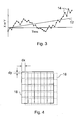
Figure 3 schematically illustrates the positional errors typical of normalised correlation; -
Figure 4 schematically illustrates the projection of a pixel array onto a fractionally shifted pixel array in accordance with an embodiment of the present invention; -
Figures 5a to 5c schematically illustrates the sub-pixel positions of neighbouring sub-pixel points about the position of a best matched pixel; -
Figure 6 schematically illustrates video metrology apparatus according to an embodiment of the present invention; -
Figure 7 schematically illustrates an aircraft structure monitoring apparatus according to an embodiment of the present invention; -
Figures 8a-8e illustrate possible deflection of image targets according to an embodiment of the present invention; -
Figures 9a and 9b schematically illustrate respectively the effect of pure shear and pure bending on a structure; -
Figure 10 schematically illustrates the addition of an offset target according to an embodiment of the present invention; and -
Figure 11 schematically illustrates a further arrangement of the aircraft monitoring apparatus ofFigure 7 . -
Figures 1a to 1c schematically illustrate a prior art method of determining the (X,Y) position of a feature within an image. In practice, a video image of the required scene is captured using a conventional CCD (charge coupled device) camera and converted to a data stream that a computer can manipulate via a frame grabber. On an image on a connected computer monitor, bounding regions are drawn around those features of the image that the user wishes to monitor the position of. Suitable software captures the pattern associated with those features and outputs an (X,Y) position corresponding to the position of each feature. The illustrated prior art method for the identification of the position of features in a video stream of no fixed geometry is known as template matching. Template matching is performed by using a correlation function to measure the degree of the similarity between two images, or parts of images. Standard correlation functions used include Normalised Greyscale Correlation (NGC), Greyscale correlation and Euclidean distance. Those skilled in the art will readily appreciate the inherent advantages and disadvantages of each of these functions. Generally speaking however, NGC provides the most desirable results and is often the correlation function of choice, such that the term Normalised Greyscale Correlation is often used to describe template matching using NGC. - The correlation function is used to find the region of an image that best matches the feature captured by the bounding region. The correlation function returns a score of how well the feature captured by the bounding region matches the underlying image when the feature captured by the bounding region is at a position (X, Y) in the image. The correlation function is evaluated at a number of (X, Y) positions in the image to determine the position that gives the best value of the correlation function. This yields the (X, Y) position of the feature within the image to the nearest pixel.
- Having located the position of the feature to the nearest pixel, its sub-pixel position can be estimated. The correlation function is evaluated at N surrounding positions.
Figures 1a to 1c schematically represent a pixel with 4, 8 and 24 nearest neighbours respectively. In each ofFigures 1a to 1c eachsmall square 2 represents an individual pixel, with the central,shaded square 4 representing the position of the feature of interest, to the nearest pixel. The neighbouring pixels at which the correlation function is evaluated, are indicated by the squares having black dots in them 6. The values of the correlation function at the N surrounding pixels are fitted to a function, such as a bi-quadratic, typically using a least-squares fitting technique. The sub-pixel position of the feature may then be estimated by differentiating the quadratic and calculating the position of its turning point since the maximum fit will occur at a turning point in the differentiated quadratic. The number N of surrounding pixels is chosen to ensure that N is at least equal or greater than the number of free parameters in the selected function, so that the function can be solved. - A typical accuracy for a good implementation of template matching using normalised greyscale correlation is in the region of 0.01 pixels, under ideal conditions. However, for certain applications such as those proposed in the monitoring of mechanical testing, or the movements of large structures, this accuracy is inadequate. Furthermore, the NGC approach has an additional technical limitation as is explained with reference to
Figures 2a and 2b . In each ofFigures 2a and 2b , each individual square represents a single pixel, with the reference feature of an image represented by the filledboxes 8. As is well known, each pixel may have a specific greyscale value anywhere between, and including, black and white. In the example shown inFigure 2a , the feature is composed initially of a series of pixels of the same greyscale, either black or white. If the next captured, or comparison, frame of the video image represents a shift of exactly an integer number of pixels, then the pattern of the comparison and reference images will be an exact match. However, if the comparison image has moved a non-integer number of pixels then the pattern will be as seen inFigure 2b . The pattern is now bounded bypixels 10 in which the greyscale value is between black and white as represented by the cross-hatching, and the pattern is clearly visually distinct from that of the reference feature. This effect is known as aliasing. - This difference in pattern due to the movement across pixel boundaries of the reference feature of interest does not disrupt the ability of the NGC approach described above to monitor the (X, Y) position to a level of accuracy in the region of 0.01 pixels. However, if the reference feature of interest is displaced by a known amount for each frame over a series of frames, the level and type of error between the actual and estimated (X, Y) position can be found. When this procedure is carried out it is seen that the normalised correlation approach generates both random and structured, or systematic, errors due to the aliasing effects. This is represented schematically in
Figure 3 . The straightline 12 represents the true X or Y position of the reference feature of interest, whereas themarkers 14 show the data points that might be calculated using the NGC approach. It can be seen that the discrepancy between actual and estimated positions have a random error, represented by the deviations of each data point from the general curve defined by them, and a systematic error represented by the deviation of the general curve from thestraight line 12, this being typical of the results of the NGC approach. - Embodiments of the present invention utilise the NGC approach to gain an initial estimate of the position of the reference feature of interest. However, two additional operations are performed to both eliminate the systematic error and refine the best estimate of the position of the reference feature of interest to give the maximum resolution.
- In embodiments of the present invention, the standard NGC technique is used to calculate an initial estimate of the sub-pixel position of the feature. The feature is then resampled by projecting the pixel array onto a new pixel array that has been shifted by a fractional part of a pixel, such that the sum of the pixel translation and the fractional part of the estimated sub-pixel position is an integer value. That is to say if the position estimate is (x½, y¼) the pixel array may be shifted by -½ a pixel in the X direction and -¼ a pixel in the Y direction. Alternatively, the pixel array may be shifted by +½ a pixel in the X direction and +¾ a pixel in the Y direction. Usually the choice of direction of translation would be such so as to minimise the magnitude of the translation. It will also be appreciated that the entire image may alternatively be translated. This is illustrated in
Figure 4 . Thesolid grid 16 represents the initial pixel array, whilst thebroken grid 18 represents the new pixel array that has been shifted by the fractional part of the current sub-pixel position estimate. The fractional part of the sub-pixel position estimate (e.g. half a pixel) is represented by dx, dy as shown inFigure 4 . The resampled pixels will now look more like the reference feature as the resampling process approximately models the aliasing effects illustrated inFigure 2 . That is to say, by shifting each pixel by a fractional part of a pixel, each pixel has either a greyscale value closer to black or white or where the greyscale value was already black or white it remains so. The correlation function is then re-evaluated at the best matched position and its N surrounding neighbours and the sub-pixel position recalculated, using the standard NGC technique. The fractional part (dx, dy) of the original sub-pixel position estimate is added to the re-evaluated best matched position to give a refined sub-pixel estimate. This procedure may be iterated a number of times to further refine the sub-pixel estimate. - A further improvement in accuracy is achieved by taking the N neighbouring samples of the correlation function at sub-pixel positions. Using pixel interpolation, recalculated pixel values may be derived and the correlation function may be evaluated at any real valued co-ordinate. This is schematically illustrated in
Figures 5a to 5c in which the 4, 8 and 24 respective neighbouring sampledpoints 20 are at sub-pixel positions. The bi-quadratic to which the values of the correlation function evaluated at the N surrounding positions is fitted may better approximate the true correlation surface near its peak value if the N neighbours are chosen to be close to the peak. This leads to an improvement in accuracy if the N neighbours are chosen to be close to the position of the best matched pixel. - Additionally or alternatively, to further refine the best estimate of the position of the reference feature of interest, use is made of a known Super Resolution techniques. As will be known to the skilled man, these techniques create a single, high resolution image from two or more similar images. The plurality of images are aligned in complete registration to sub-pixel accuracy. The information present in the aligned images is then combined using any known Super Resolution technique, to produce a single, high resolution image, (i.e. more pixels than any of the originals).
- Super Resolution is applied here to generate a high resolution representation of the feature. Multiple images containing the feature are available and using the techniques described above the position of the feature is known within each image to sub-pixel accuracy. The images can therefore be aligned such that the feature appears in complete registration throughout the image set. A high resolution version of the feature can then be calculated.
- Use of the high resolution feature can be made in the technique described in relation to
Figures 5a to 5c , where more accurate pixel interpolation can be accomplished. Hence the evaluation of the correlation function at the N sub-pixel nearest neighbour sample points 20 can be more accurate still. The high resolution representation of the feature also enables the feature translation used in refining the initial estimate of the position of a feature to be accomplished to a higher accuracy. - Mechanical testing or structural monitoring applications are well suited to employing Super Resolution techniques as generally the monitored image is changing slowly. Therefore, each frame is only marginally different from subsequent frames. The use of this technique allows the use of simple low pixel count cameras to approach the results that would be possible with much more costly high pixel count cameras.
- The process of sequentially applying these refinement techniques to the raw data available from the known NGC algorithms improves resolution by a factor of about 5 and removes the systematic errors. These features enable the use of a video camera to monitor the strains or deflections in mechanical tests of materials or structures to the same level of accuracy as is possible with conventional methods of measurement such as extensometers, strain gauges or LVDTs.
-
Figure 6 schematically shows video metrology equipment constituting an embodiment of the present invention. Atest sample 22 having avisual target 24 marked thereon, is placed in atest machine 26. The test machine is arranged to apply a slowly increasing tensile load to thetest sample 22. Avideo camera 28 is arranged to monitor thetest sample 22 at thetarget location 24 and providesvideo data 30 to aprocessor 32. The processor also receives sample load data from the test machine. The processor is arranged to implement the method of the present invention as described hereinabove. Amonitor 34 is coupled to theprocessor 32 and is arranged to show the captured video image, or results of the image processing performed by the processor. - The
processor 32 includes a comparator for comparing the determined position of an object or feature from a sequence images received from thevideo camera 28. The compared positions allow any dimensional changes, such as stretching or deflection, of thetest sample 22 to be identified and measured very accurately. The sequence of images received from thevideo camera 28 may be each video frame, or may be more widely separated in time as is appropriate. - A feature selector (not shown) may also be included within the equipment to allow manual or automatic selection of an object or feature within an image to be made. The feature selector may, for example, comprise circuitry arranged to generate a bounding region superimposed on the image displayed on the
monitor 34, the position of the bounding box being controllable by a user, or may utilise image recognition technology to select a feature. An object or feature of interest is thus enclosed by the bounding box and identified to theimage processor 32 as the object the position of which is to be determined. - The video capture and analysis apparatus may equally be used as a simple positioning system, the position of an object being determinable to a high level of accuracy. This has applications in precise 'pick and place' operations, such as within integrated circuit manufacture.
- This invention offers a substantial improvement in resolution compared to the video metrology approaches of the prior art and gives results that are equivalent to those obtained by conventional extensometers or strain gauges. Furthermore, the invention is not limited to specific high contrasts target geometries and can utilise the natural markings on samples, thus avoiding problems with applying targets. This freedom of target geometry and contrast allows very small samples to be tested, permitting full advantage to be taken of the scale insensitivity inherent in video metrology.
- Whilst the basic application of embodiments of the present invention discussed herein is the precision measurement of dimensional changes and test samples undergoing mechanical tests (extensometry), additional applications exist. For example, the monitoring of civil engineering structures such as bridges and buildings, precision placement of articles such as microchips in a production setting, the measurement of human gait, and other similar applications. Additionally, using two or more cameras so as to be able to obtain precision movement data in three dimensions further extends a range of potential fields of application.
- An application of video metrology is in the monitoring of deformations in the main fuselage, or other structural elements, of an aircraft. An example of a suitable arrangement of apparatus is shown in
Figure 7 . Acamera 40 or cameras is rigidly attached to a fixedpoint 42 or points on theaircraft structure 44 and trained along the fuselage to image a set oftargets 46 some distance away, also rigidly attached to the aircraft structure. - The
camera 40 andtargets 46 could be within the aircraft cabin(s) or cargo hold(s), or be mounted externally. In one embodiment twotargets 46', 46" are to be used. The image of the two targets are provided by thecamera 40 to a suitable computer and are captured by appropriate software and their position in subsequent frames tracked using algorithms such as, but not exclusively, grey scale normalised correlation. The particularly suitable robust and high accuracy video gauging approach described herein may be used but any suitable position tracking technique could also be utilised. The position of the targets in pixels is constantly determined by the computer and converted into real dimensions. - The use of two targets permits vertical and horizontal deflections to be measured and any twisting of the fuselage to be identified, corresponding to pitch, yaw and roll deformations. This is illustrated in
Figures 8a to 8e . Each possible deflection of the imaged targets is shown separately inFigures 8a to 8d and combined inFigure 8e. Figures 8b and 8c respectively show the target deflections that would be caused by vertical and horizontal shear or bending of the fuselage.Figure 8d shows the target deflection caused by torsion, or twisting, of the fuselage. -
Figures 9a and 9b show the difference between shear and bending and illustrates how these two deformation modes can be separated.Figure 9a shows pure shear. In this case thevertical lines targets 46' and 46" remains unchanged.Figure 9b shows pure bending. In this case thevertical lines - However, for small bending deflections the change in distance is difficult to readily detect. The addition of another target(s) 54, offset from the plane of the first target(s) 46', 46", as shown in
Figure 10 overcomes this difficulty by providing anadequate lever arm 56 to multiply the deformation into the readily measurable range. - An alternative way of separating out shear and bending deformations is to mount an
additional target 60 at a known relative position to thecamera 40 but view it in amirror 62 mounted in the same plane as thetarget 46 as shown inFigure 11 . The image of theadditional target 60 in the mirror would only appear to move with a bending deformation and would be completely insensitive to pure shear or torsional deformations. - The monitoring software may include automatic target detection functions to reacquire targets lost, for example, by momentary obscuration by passengers or flight crew. A greater number of targets than two would be of benefit in terms of providing redundant data channels, and of limiting obscuration issues. In an embodiment two cameras may be placed back to back in fixed register with each other at the mid point of the fuselage, or cabin, with targets at each end of the fuselage, or cabin, to provide an unambiguous picture of the totality of the deflections in the cabin. A particularly suitable form of target and target carrier is an illuminated panel upon which the targets are marked as areas of differential illumination. LEDs or similar high reliability light sources can be utilised. Such targets would minimise any influence of the level of cabin illumination on the accuracy of the monitoring function. However other suitable targets may also be used. For multicabin aircraft each cabin may be monitored individually or the optimum cabin for monitoring may be identified by an examination of the overall structural response of the airframe. Equally, the cameras and targets may be mounted externally to the fuselage to provide similar data on wing, rudder or tail deflections.
- An alternative approach is to use a sealed monitoring unit, as also shown in
Figure 11 . This incorporates the camera(s), targets, light source(s) and mirrors into a sealed butflexible tube 64, which can be mounted, for example, between fuselage frames in the cargo bay or between ribs in the wing. The tube acts as a shroud to prevent people and/or objects from obscuring the targets from the camera and block out the effects of changes in ambient lighting. - The monitoring function takes place in the image space so that the overall dimensional resolution of this system can be adjusted as required by the use of suitable lenses on the cameras. The high accuracy video gauging approach described herein is capable of a proven resolution better than 0.005 pixels for a single target and a conventional, low cost camera will have an image field of more than 500 pixels, giving a resolution of 1 part in 100,000.
- From these figures an example of the potential sensitivity of the measurement of structural response can be calculated. If the image field in which the targets are situated has a physical size of 100mm square the deflections of targets that can be detected are of the order of 1µm. If the initial distance between two targets is 50mm within that image field then the angular deformation in the torsional sense that can be detected between those targets is of the order of 0.002°. For a change in angle from the vertical plane of 0.1°, due to bending, the apparent change in distance between two targets 50mm apart is less than 0.1µm, which is not resolvable. However, if a second target set is mounted as shown in
Figure 10 (i.e. rigidly normal to the mounting point of the first set with a dimensional offset between them) with an offset of 50mm, then the apparent movement of that target is more than 80µm, which is readily resolvable. The change in angle from the vertical plane is assessed via the relationship between the two offset target sets and an angular resolution of the order of 0.002° is achievable. Changes in the offset distance may be used to regulate this resolution. It should be noted that the offset need not be achieved with physical structure, a small LED laser could be used to shine on a translucent screen, with that laser spot being taken as the target. In this case the offset could be as great as required without any difficulties due to the response of the structure utilised to generate the dimensional offset. - By viewing a target with two or more cameras the position of the target can be measured in 3D. A single camera is sufficient to measure the 3D position and orientation of an object that has 3 or more targets attached.
- For any particular airframe the maximum structural deflections would be found by interrogating the design and structural analyses and appropriately sized targets, image fields and lens systems determined. Wing deflections are substantially greater than fuselage deflections. However, this would not influence the basic approach, merely requiring the use of a different lens system to provide an appropriately scaled target image field and targets. The data acquired by the gauging system can be interrogated by an appropriate computer system and events that exceeded a predetermined level or levels logged. In this way the loadings on the specific airframe can be monitored and summed for comparison with models of the design fatigue life of the airframe and structurally safe maintenance or inspection intervals determined. Additionally, any very severe events that fall outside the design envelope can be instantly detected to trigger remedial actions.
Claims (28)
- A method of determining the coordinates of a feature within an image, the image comprising a plurality of pixels (2), the method comprising:determining an estimate of the coordinates of the feature to within a fraction of a pixel;translating the feature relative to the pixels such that the sum of the pixel fraction of the initial estimated coordinates and the pixel translation is an integer value;determining a further estimate of the coordinates of the translated feature within the image to within a fraction of a pixel; anddetermining a refined estimate of the feature coordinates by summing the pixel fraction of the previous estimate of the coordinates with the further estimate of coordinates.
- A method according to claim 1, wherein the first and second determining steps comprise:correlating the image feature and image using a predetermined correlation function to determine the coordinates of the feature within the image to the nearest pixel;evaluating the correlation function at a plurality of pixel positions in the neighbourhood of the determined coordinates and fitting the plurality of values to a further function; anddifferentiating the further function to determine its turning point, whereby the coordinates corresponding to the turning point provide the coordinates of the feature to within a said fraction of a pixel.
- A method according to claim 2, wherein said correlation function is evaluated at a plurality of sub-pixel positions (20).
- A method according to claim 3, wherein the sub-pixel positions are in closer proximity to the determined coordinates than the pixel positions.
- A method according to any preceding claim, the method further comprising:determining the coordinates of the feature within a further image, the position of the further image being known relative to the first image;determining the difference in position of the feature between the first and further image;superimposing said first and further image such that said feature is substantially in registration; andapplying a Super Resolution technique to said superimposed images, whereby an increased resolution representation of said feature is produced.
- A method according to any one of claims 2 to 4, wherein said predetermined correlation function comprises a normalised greyscale correlation function.
- A method according to any preceding claim, wherein the translating step, second determining step and summing step are repeated at least once.
- A method of measuring dimensional changes in a sample (22), the method comprising:capturing at least two images of the sample, each image being captured at a different time with respect to one another;determining the coordinates of a feature (24) within each image in accordance with the method of any one of claims 1 to 7; andcomparing the determined coordinates of the feature to determine any dimensional changes in the sample.
- Positioning apparatus for determining the coordinates of a feature, the apparatus comprising:an image capture device (28) arranged to provide an image encompassing the feature, the image comprising a plurality of pixels; andan image processor (32) arranged to receive the captured image and determine the coordinates of the feature by executing the method steps of any one of claims 1 to 7.
- Positioning apparatus according to claim 9, further comprising a monitor (34) arranged to receive and display the captured image and feature selection means arranged to select a feature within the displayed image and identify the selected feature to the image processor.
- Positioning apparatus according to claim 9, further comprising at least one further image capture device at a known spatial relationship to the first image capture device, and wherein the image processor is further arranged to determine the coordinates of the feature in the image received for each of the image capture devices and, given the known spatial relationship of the image capture devices, thereby determining the 3-dimensional coordinates of the feature.
- Measurement apparatus for detecting dimensional changes in a sample, the apparatus comprising:an image capture device arranged to sequentially provide a plurality of images encompassing a feature, each image comprising a plurality of pixels;an image processor arranged to sequentially receive the plurality of captured images and determine the coordinates of the feature from each image by executing the method steps of any one of claims 1 to 7; anda position comparator arranged to compare the determined coordinates of the feature for each image and determine if the determined coordinates change between images.
- Measurement apparatus according to claim 12 further arranged to determine the magnitude and/or direction of the determined change in coordinates.
- Measurement apparatus according to claim 12 or 13, further comprising at least one further image capture device (28) at a known spatial relationship to the first image capture device, and wherein the image processor is further arranged to determine the coordinates of the feature in the image received for each of the image capture devices and, given the known spatial relationship of the image capture devices, thereby determining the 3-dimensional coordinates of the feature.
- A method of determining the 3-dimensional coordinates of a feature, the method comprising:providing at least two image capture devices each arranged to capture an image including the feature;determining the position of each of said image capture devices with respect to one another;determining the coordinates of the feature within each image in accordance with the method of any one of claims 1 to 7, and calculating the 3-dimensional coordinates of the feature given the determined feature coordinates in each image and the determined relative positions of each image capture device.
- A method of measuring 3-dimensional changes in a sample, the method comprising:providing at least two image capture devices at a known spatial relationship to one another;capturing at least two images of the sample with each image capture device, the two images being captured at a different time from one another;determining the 2-dimensional coordinates of a feature within each image in accordance with the method of any one of claims 1 to 7;calculating the 3-dimensional coordinates of the feature from the first and second images from the 2-dimensional coordinates and spatial relationship of the image capture devices; andcomparing the 3-dimensional coordinates to determine any dimensional changes in the sample.
- A method of monitoring an aircraft structure, the method comprising the steps of attaching one or more image captures devices (40) to a first portion of an aircraft structure (44), attaching one or more targets (46) to a second portion of the aircraft structure, the or each target being within the field of view of the or each image capture device, capturing a series of images from the or each image capture device and processing the captured images to determine the magnitude and/or direction of movement of the or each target, wherein the processing step comprises determining the coordinates of the or each target in each frame of the series of frames according to the method of claim 1.
- A method according to claim 17, wherein said method comprises attaching at least three targets to the second portion of the aircraft structure at known relative positions to the second portion of the aircraft, the at least three targets being within the field of view of the or each image capture device, whereby the position and orientation of said second portion of the aircraft relative to the or each image capture device is determined by said processing step.
- A method according to claim 17 or 18, wherein the or at least one of the targets is orthogonally offset from the plane of the second portion of aircraft structure to which it is attached.
- A method according to claim 17 or 18, wherein a reflective surface (62) is attached to the aircraft structure such that at least one of said targets is within the field of view of at least one of said image capture devices when viewed through said reflective structure.
- A method according to any one of claims 17 to 20, wherein the or each image capture device is arranged to automatically identify the or each target as an item of interest.
- A method according to any one of claims 17 to 21, wherein the aircraft structure comprises a portion of a wing, empennage or fuselage.
- An aircraft structure monitoring apparatus comprising:at least one image capture device (40) arranged to be attached to a first portion of an aircraft structure (44);at least one target (46) arranged to be attached to a second portion of the aircraft structure, whereby the at least one target is within the field of view of the at least one image capture device; andan image processor (32) arranged to receive a plurality of images from the at least one image capture device and process said received images to determine the magnitude and/or direction of movement of the at least one target by determining the coordinates of the target in each image according to the method of claim 1.
- An aircraft structure monitoring apparatus according to claim 23, wherein at least one first further target (46") is arranged to be attached in a plane orthogonally offset from the plane in which the at least one target is arranged to be attached.
- An aircraft structure monitoring apparatus according to claim 23, wherein a reflective element (62) is arranged to be attached to the second portion of the aircraft structure such that said at least one target is within the field of view of said at least one image capture device when viewed through said reflective surface.
- An aircraft structure monitoring apparatus according to claim 23, 24 or 25, wherein said image processor is arranged to automatically identify the least one target.
- An aircraft structure monitoring apparatus according to any one of claims 23 to 26, wherein the or each target comprises an illuminated panel including areas of differential illumination.
- An aircraft structure monitoring apparatus according to any one of claims 23 to 27, further comprising a plurality of image capture devices and/or a plurality of targets.
Applications Claiming Priority (3)
| Application Number | Priority Date | Filing Date | Title |
|---|---|---|---|
| GB0224923 | 2002-10-25 | ||
| GB0224923A GB2394543A (en) | 2002-10-25 | 2002-10-25 | Positional measurement of a feature within an image |
| PCT/GB2003/004606 WO2004038328A2 (en) | 2002-10-25 | 2003-10-23 | Positional measurement of a feature within an image and monitoring an aircraft structure |
Publications (2)
| Publication Number | Publication Date |
|---|---|
| EP1563252A2 EP1563252A2 (en) | 2005-08-17 |
| EP1563252B1 true EP1563252B1 (en) | 2014-10-01 |
Family
ID=9946622
Family Applications (1)
| Application Number | Title | Priority Date | Filing Date |
|---|---|---|---|
| EP03769646.5A Expired - Lifetime EP1563252B1 (en) | 2002-10-25 | 2003-10-23 | Positional measurement of a feature within an image and monitoring an aircraft structure |
Country Status (5)
| Country | Link |
|---|---|
| US (1) | US8718403B2 (en) |
| EP (1) | EP1563252B1 (en) |
| AU (1) | AU2003278336A1 (en) |
| GB (1) | GB2394543A (en) |
| WO (1) | WO2004038328A2 (en) |
Families Citing this family (27)
| Publication number | Priority date | Publication date | Assignee | Title |
|---|---|---|---|---|
| JP4172416B2 (en) * | 2004-04-22 | 2008-10-29 | 国立大学法人東京工業大学 | Movement determination method for capturing sub-pixel motion image suitable for super-resolution processing, imaging apparatus using the same, and evaluation method of movement direction |
| US7593501B2 (en) * | 2005-01-06 | 2009-09-22 | Areva Np Inc. | Segment make-up system and method for manufacturing nuclear fuel rods |
| US7796116B2 (en) | 2005-01-12 | 2010-09-14 | Thinkoptics, Inc. | Electronic equipment for handheld vision based absolute pointing system |
| US7417670B1 (en) * | 2005-01-12 | 2008-08-26 | Ambarella, Inc. | Digital video camera with binning or skipping correction |
| US7477360B2 (en) * | 2005-02-11 | 2009-01-13 | Deltasphere, Inc. | Method and apparatus for displaying a 2D image data set combined with a 3D rangefinder data set |
| US7477359B2 (en) * | 2005-02-11 | 2009-01-13 | Deltasphere, Inc. | Method and apparatus for making and displaying measurements based upon multiple 3D rangefinder data sets |
| US7974461B2 (en) | 2005-02-11 | 2011-07-05 | Deltasphere, Inc. | Method and apparatus for displaying a calculated geometric entity within one or more 3D rangefinder data sets |
| US7403268B2 (en) * | 2005-02-11 | 2008-07-22 | Deltasphere, Inc. | Method and apparatus for determining the geometric correspondence between multiple 3D rangefinder data sets |
| US7777761B2 (en) * | 2005-02-11 | 2010-08-17 | Deltasphere, Inc. | Method and apparatus for specifying and displaying measurements within a 3D rangefinder data set |
| US20060238508A1 (en) * | 2005-04-22 | 2006-10-26 | Tong Xie | Optical location measuring system |
| WO2007015271A1 (en) * | 2005-08-02 | 2007-02-08 | Fidia S.P.A. | Precision displacement measuring system and method for industrial machines |
| US7763875B2 (en) | 2005-09-07 | 2010-07-27 | Romanov Nikolai L | System and method for sensing position utilizing an uncalibrated surface |
| US7551771B2 (en) | 2005-09-20 | 2009-06-23 | Deltasphere, Inc. | Methods, systems, and computer program products for acquiring three-dimensional range information |
| US8913003B2 (en) | 2006-07-17 | 2014-12-16 | Thinkoptics, Inc. | Free-space multi-dimensional absolute pointer using a projection marker system |
| US9176598B2 (en) | 2007-05-08 | 2015-11-03 | Thinkoptics, Inc. | Free-space multi-dimensional absolute pointer with improved performance |
| DE102007037726B4 (en) | 2007-08-09 | 2010-07-08 | Lavision Gmbh | Method for the non-contact measurement of deformations of a surface of a measured object |
| US9446840B2 (en) * | 2008-07-01 | 2016-09-20 | The Boeing Company | Systems and methods for alleviating aircraft loads with plasma actuators |
| DE102009007938A1 (en) | 2009-02-06 | 2010-08-19 | Baumer Innotec Ag | Measuring device for measuring deformations of elastically deformable objects |
| JP6177895B2 (en) * | 2012-05-24 | 2017-08-09 | シーメンス・ヘルスケア・ダイアグノスティックス・インコーポレーテッドSiemens Healthcare Diagnostics Inc. | Non-contact optical encoding scheme for intelligent automation pack |
| US10462361B2 (en) | 2017-09-26 | 2019-10-29 | Rosemount Aerospace Inc. | Seeker with dynamic resolution imaging |
| EP3754292A1 (en) * | 2019-06-19 | 2020-12-23 | Intelligent Contruction Safety Systems Spolka Z Ograniczona Odpowiedzialnoscia | A system for measuring deformations and a method for measuring deformations |
| US11803943B2 (en) * | 2019-06-25 | 2023-10-31 | Illinois Tool Works Inc. | Brightness and contrast correction for video extensometer systems and methods |
| CA3188141A1 (en) * | 2020-06-30 | 2022-01-06 | Kneedly Ab | Solution for determination of supraphysiological body joint movements |
| CN112945117B (en) * | 2021-01-26 | 2022-07-08 | 广西建宏工程科技有限公司 | Movable bridge deflection detector for bridge engineering detection |
| GB2618524B (en) * | 2022-05-02 | 2025-02-05 | Imetrum Ltd | Non-contact deformation monitoring system |
| KR20250022019A (en) * | 2022-06-10 | 2025-02-14 | 슈퍼널, 엘엘씨 | Camera calibration using vehicle features |
| CN116258674B (en) * | 2022-12-29 | 2025-11-07 | 凌云光技术股份有限公司 | Method and device for evaluating quality of assembly of visual inspection system |
Citations (1)
| Publication number | Priority date | Publication date | Assignee | Title |
|---|---|---|---|---|
| EP0999521A2 (en) * | 1998-11-05 | 2000-05-10 | Tektronix, Inc. | High precision sub-pixel spatial alignment of digital images |
Family Cites Families (17)
| Publication number | Priority date | Publication date | Assignee | Title |
|---|---|---|---|---|
| US4640200A (en) * | 1984-06-11 | 1987-02-03 | Shure Manufacturing Corporation | Pass-through transaction drawer with removable deal tray |
| US4805123B1 (en) * | 1986-07-14 | 1998-10-13 | Kla Instr Corp | Automatic photomask and reticle inspection method and apparatus including improved defect detector and alignment sub-systems |
| GB9019538D0 (en) * | 1990-09-07 | 1990-10-24 | Philips Electronic Associated | Tracking a moving object |
| GB9325922D0 (en) * | 1993-12-18 | 1994-02-23 | Kodak Ltd | Detection of global translations between images |
| US5640200A (en) * | 1994-08-31 | 1997-06-17 | Cognex Corporation | Golden template comparison using efficient image registration |
| US5850466A (en) * | 1995-02-22 | 1998-12-15 | Cognex Corporation | Golden template comparison for rotated and/or scaled images |
| JP3120767B2 (en) * | 1998-01-16 | 2000-12-25 | 日本電気株式会社 | Appearance inspection device, appearance inspection method, and recording medium recording appearance inspection program |
| US6208769B1 (en) * | 1998-05-28 | 2001-03-27 | Acuity Imaging, Llc | Method of accurately locating the fractional position of a template match point |
| US6477275B1 (en) * | 1999-06-16 | 2002-11-05 | Coreco Imaging, Inc. | Systems and methods for locating a pattern in an image |
| US6628845B1 (en) * | 1999-10-20 | 2003-09-30 | Nec Laboratories America, Inc. | Method for subpixel registration of images |
| US7106885B2 (en) * | 2000-09-08 | 2006-09-12 | Carecord Technologies, Inc. | Method and apparatus for subject physical position and security determination |
| IL141650A (en) * | 2001-02-26 | 2005-12-18 | Elop Electrooptics Ind Ltd | Method and system for tracking an object |
| US7085431B2 (en) * | 2001-11-13 | 2006-08-01 | Mitutoyo Corporation | Systems and methods for reducing position errors in image correlation systems during intra-reference-image displacements |
| US7155052B2 (en) * | 2002-06-10 | 2006-12-26 | Tokyo Seimitsu (Israel) Ltd | Method for pattern inspection |
| US7272252B2 (en) * | 2002-06-12 | 2007-09-18 | Clarient, Inc. | Automated system for combining bright field and fluorescent microscopy |
| US6961481B2 (en) * | 2002-07-05 | 2005-11-01 | Lockheed Martin Corporation | Method and apparatus for image processing using sub-pixel differencing |
| WO2004025567A2 (en) * | 2002-09-12 | 2004-03-25 | Nline Corporation | System and method for acquiring and processing complex images |
-
2002
- 2002-10-25 GB GB0224923A patent/GB2394543A/en not_active Withdrawn
-
2003
- 2003-10-23 WO PCT/GB2003/004606 patent/WO2004038328A2/en not_active Ceased
- 2003-10-23 US US10/532,438 patent/US8718403B2/en active Active
- 2003-10-23 EP EP03769646.5A patent/EP1563252B1/en not_active Expired - Lifetime
- 2003-10-23 AU AU2003278336A patent/AU2003278336A1/en not_active Abandoned
Patent Citations (1)
| Publication number | Priority date | Publication date | Assignee | Title |
|---|---|---|---|---|
| EP0999521A2 (en) * | 1998-11-05 | 2000-05-10 | Tektronix, Inc. | High precision sub-pixel spatial alignment of digital images |
Also Published As
| Publication number | Publication date |
|---|---|
| AU2003278336A8 (en) | 2004-05-13 |
| WO2004038328A3 (en) | 2004-08-26 |
| EP1563252A2 (en) | 2005-08-17 |
| US20060115133A1 (en) | 2006-06-01 |
| GB2394543A (en) | 2004-04-28 |
| GB0224923D0 (en) | 2002-12-04 |
| AU2003278336A1 (en) | 2004-05-13 |
| US8718403B2 (en) | 2014-05-06 |
| WO2004038328A2 (en) | 2004-05-06 |
Similar Documents
| Publication | Publication Date | Title |
|---|---|---|
| US8718403B2 (en) | Positional measurement of a feature within an image | |
| Burner et al. | Videogrammetric model deformation measurement technique | |
| Barazzetti et al. | Crack measurement: Development, testing and applications of an automatic image-based algorithm | |
| Maas et al. | Photogrammetric techniques in civil engineering material testing and structure monitoring | |
| US5726907A (en) | Biaxial non-contacting strain measurement using machine vision | |
| AU664393B2 (en) | Method and system for point by point measurement of spatial coordinates | |
| CN103575227A (en) | Vision extensometer implementation method based on digital speckles | |
| Ganci et al. | Automation in videogrammetry | |
| WO2017119202A1 (en) | Structure member specifying device and method | |
| CN112665523B (en) | Combined measurement method for complex profile | |
| CN119146872A (en) | Building deformation photographic monitoring method for constructional engineering | |
| CN112525161A (en) | Rotating shaft calibration method | |
| KR101232611B1 (en) | Instrumentation system using alignment scope and method for instrumentation position | |
| CN114266835B (en) | A deformation monitoring control method and system for non-measuring cameras | |
| Burner et al. | In-flight aeroelastic measurement technique development | |
| Bottalico et al. | Preliminary validation of a hybrid visual-inertial stereocamera calibration for 3D point tracking using independent UAVs | |
| Zhao et al. | Study on the Technologies of Close Range Photogrammetry and Applications in the Manufacture of Aviation | |
| Li et al. | Study of natural patterns on digital image correlation using simulation method | |
| CN115355884B (en) | Relative pose measuring device and method for ship bearing | |
| Takhirov | Measuring Centers of Special Targets in Digital Still Images and Movie Frames: Approach and Evaluation. | |
| Wang et al. | Characterization of large deflection with a monocular deflectometer | |
| Tang et al. | Calibration device for test sieves based on image measuring instrument | |
| Walters et al. | Feasibility Study of a Motion Capture Based, Moveable Three-Dimensional Digital Image Correlation System | |
| JPH04346004A (en) | Displacement measuring apparatus | |
| Cooper et al. | Photograninictric methods for monitoring deformation: Theory, practice and potential |
Legal Events
| Date | Code | Title | Description |
|---|---|---|---|
| PUAI | Public reference made under article 153(3) epc to a published international application that has entered the european phase |
Free format text: ORIGINAL CODE: 0009012 |
|
| 17P | Request for examination filed |
Effective date: 20050523 |
|
| AK | Designated contracting states |
Kind code of ref document: A2 Designated state(s): AT BE BG CH CY CZ DE DK EE ES FI FR GB GR HU IE IT LI LU MC NL PT RO SE SI SK TR |
|
| AX | Request for extension of the european patent |
Extension state: AL LT LV MK |
|
| DAX | Request for extension of the european patent (deleted) | ||
| 17Q | First examination report despatched |
Effective date: 20060714 |
|
| RAP1 | Party data changed (applicant data changed or rights of an application transferred) |
Owner name: IMETRUM LIMITED |
|
| REG | Reference to a national code |
Ref country code: DE Ref legal event code: R079 Ref document number: 60346828 Country of ref document: DE Free format text: PREVIOUS MAIN CLASS: G01B0011160000 Ipc: G06T0007000000 |
|
| RIC1 | Information provided on ipc code assigned before grant |
Ipc: G06T 7/00 20060101AFI20140226BHEP Ipc: G06K 9/32 20060101ALI20140226BHEP Ipc: G06T 7/20 20060101ALI20140226BHEP |
|
| GRAP | Despatch of communication of intention to grant a patent |
Free format text: ORIGINAL CODE: EPIDOSNIGR1 |
|
| INTG | Intention to grant announced |
Effective date: 20140423 |
|
| GRAS | Grant fee paid |
Free format text: ORIGINAL CODE: EPIDOSNIGR3 |
|
| GRAA | (expected) grant |
Free format text: ORIGINAL CODE: 0009210 |
|
| AK | Designated contracting states |
Kind code of ref document: B1 Designated state(s): AT BE BG CH CY CZ DE DK EE ES FI FR GB GR HU IE IT LI LU MC NL PT RO SE SI SK TR |
|
| REG | Reference to a national code |
Ref country code: GB Ref legal event code: FG4D |
|
| REG | Reference to a national code |
Ref country code: AT Ref legal event code: REF Ref document number: 689852 Country of ref document: AT Kind code of ref document: T Effective date: 20141015 Ref country code: CH Ref legal event code: EP |
|
| REG | Reference to a national code |
Ref country code: IE Ref legal event code: FG4D |
|
| REG | Reference to a national code |
Ref country code: DE Ref legal event code: R096 Ref document number: 60346828 Country of ref document: DE Effective date: 20141113 |
|
| REG | Reference to a national code |
Ref country code: NL Ref legal event code: VDEP Effective date: 20141001 |
|
| REG | Reference to a national code |
Ref country code: AT Ref legal event code: MK05 Ref document number: 689852 Country of ref document: AT Kind code of ref document: T Effective date: 20141001 |
|
| PG25 | Lapsed in a contracting state [announced via postgrant information from national office to epo] |
Ref country code: NL Free format text: LAPSE BECAUSE OF FAILURE TO SUBMIT A TRANSLATION OF THE DESCRIPTION OR TO PAY THE FEE WITHIN THE PRESCRIBED TIME-LIMIT Effective date: 20141001 |
|
| PG25 | Lapsed in a contracting state [announced via postgrant information from national office to epo] |
Ref country code: FI Free format text: LAPSE BECAUSE OF FAILURE TO SUBMIT A TRANSLATION OF THE DESCRIPTION OR TO PAY THE FEE WITHIN THE PRESCRIBED TIME-LIMIT Effective date: 20141001 Ref country code: PT Free format text: LAPSE BECAUSE OF FAILURE TO SUBMIT A TRANSLATION OF THE DESCRIPTION OR TO PAY THE FEE WITHIN THE PRESCRIBED TIME-LIMIT Effective date: 20150202 Ref country code: ES Free format text: LAPSE BECAUSE OF FAILURE TO SUBMIT A TRANSLATION OF THE DESCRIPTION OR TO PAY THE FEE WITHIN THE PRESCRIBED TIME-LIMIT Effective date: 20141001 Ref country code: CZ Free format text: LAPSE BECAUSE OF FAILURE TO SUBMIT A TRANSLATION OF THE DESCRIPTION OR TO PAY THE FEE WITHIN THE PRESCRIBED TIME-LIMIT Effective date: 20141001 |
|
| PG25 | Lapsed in a contracting state [announced via postgrant information from national office to epo] |
Ref country code: AT Free format text: LAPSE BECAUSE OF FAILURE TO SUBMIT A TRANSLATION OF THE DESCRIPTION OR TO PAY THE FEE WITHIN THE PRESCRIBED TIME-LIMIT Effective date: 20141001 Ref country code: GR Free format text: LAPSE BECAUSE OF FAILURE TO SUBMIT A TRANSLATION OF THE DESCRIPTION OR TO PAY THE FEE WITHIN THE PRESCRIBED TIME-LIMIT Effective date: 20150102 Ref country code: CY Free format text: LAPSE BECAUSE OF FAILURE TO SUBMIT A TRANSLATION OF THE DESCRIPTION OR TO PAY THE FEE WITHIN THE PRESCRIBED TIME-LIMIT Effective date: 20141001 Ref country code: SE Free format text: LAPSE BECAUSE OF FAILURE TO SUBMIT A TRANSLATION OF THE DESCRIPTION OR TO PAY THE FEE WITHIN THE PRESCRIBED TIME-LIMIT Effective date: 20141001 |
|
| REG | Reference to a national code |
Ref country code: CH Ref legal event code: PL |
|
| PG25 | Lapsed in a contracting state [announced via postgrant information from national office to epo] |
Ref country code: MC Free format text: LAPSE BECAUSE OF FAILURE TO SUBMIT A TRANSLATION OF THE DESCRIPTION OR TO PAY THE FEE WITHIN THE PRESCRIBED TIME-LIMIT Effective date: 20141001 Ref country code: BE Free format text: LAPSE BECAUSE OF NON-PAYMENT OF DUE FEES Effective date: 20141031 |
|
| REG | Reference to a national code |
Ref country code: DE Ref legal event code: R097 Ref document number: 60346828 Country of ref document: DE |
|
| REG | Reference to a national code |
Ref country code: IE Ref legal event code: MM4A |
|
| PG25 | Lapsed in a contracting state [announced via postgrant information from national office to epo] |
Ref country code: EE Free format text: LAPSE BECAUSE OF FAILURE TO SUBMIT A TRANSLATION OF THE DESCRIPTION OR TO PAY THE FEE WITHIN THE PRESCRIBED TIME-LIMIT Effective date: 20141001 Ref country code: SK Free format text: LAPSE BECAUSE OF FAILURE TO SUBMIT A TRANSLATION OF THE DESCRIPTION OR TO PAY THE FEE WITHIN THE PRESCRIBED TIME-LIMIT Effective date: 20141001 Ref country code: LI Free format text: LAPSE BECAUSE OF NON-PAYMENT OF DUE FEES Effective date: 20141031 Ref country code: DK Free format text: LAPSE BECAUSE OF FAILURE TO SUBMIT A TRANSLATION OF THE DESCRIPTION OR TO PAY THE FEE WITHIN THE PRESCRIBED TIME-LIMIT Effective date: 20141001 Ref country code: CH Free format text: LAPSE BECAUSE OF NON-PAYMENT OF DUE FEES Effective date: 20141031 Ref country code: RO Free format text: LAPSE BECAUSE OF FAILURE TO SUBMIT A TRANSLATION OF THE DESCRIPTION OR TO PAY THE FEE WITHIN THE PRESCRIBED TIME-LIMIT Effective date: 20141001 |
|
| PLBE | No opposition filed within time limit |
Free format text: ORIGINAL CODE: 0009261 |
|
| STAA | Information on the status of an ep patent application or granted ep patent |
Free format text: STATUS: NO OPPOSITION FILED WITHIN TIME LIMIT |
|
| 26N | No opposition filed |
Effective date: 20150702 |
|
| REG | Reference to a national code |
Ref country code: FR Ref legal event code: PLFP Year of fee payment: 13 |
|
| PG25 | Lapsed in a contracting state [announced via postgrant information from national office to epo] |
Ref country code: IE Free format text: LAPSE BECAUSE OF NON-PAYMENT OF DUE FEES Effective date: 20141023 |
|
| PG25 | Lapsed in a contracting state [announced via postgrant information from national office to epo] |
Ref country code: SI Free format text: LAPSE BECAUSE OF FAILURE TO SUBMIT A TRANSLATION OF THE DESCRIPTION OR TO PAY THE FEE WITHIN THE PRESCRIBED TIME-LIMIT Effective date: 20141001 |
|
| PG25 | Lapsed in a contracting state [announced via postgrant information from national office to epo] |
Ref country code: BG Free format text: LAPSE BECAUSE OF FAILURE TO SUBMIT A TRANSLATION OF THE DESCRIPTION OR TO PAY THE FEE WITHIN THE PRESCRIBED TIME-LIMIT Effective date: 20141001 |
|
| PG25 | Lapsed in a contracting state [announced via postgrant information from national office to epo] |
Ref country code: TR Free format text: LAPSE BECAUSE OF FAILURE TO SUBMIT A TRANSLATION OF THE DESCRIPTION OR TO PAY THE FEE WITHIN THE PRESCRIBED TIME-LIMIT Effective date: 20141001 Ref country code: LU Free format text: LAPSE BECAUSE OF NON-PAYMENT OF DUE FEES Effective date: 20141023 Ref country code: HU Free format text: LAPSE BECAUSE OF FAILURE TO SUBMIT A TRANSLATION OF THE DESCRIPTION OR TO PAY THE FEE WITHIN THE PRESCRIBED TIME-LIMIT; INVALID AB INITIO Effective date: 20031023 |
|
| REG | Reference to a national code |
Ref country code: FR Ref legal event code: PLFP Year of fee payment: 14 |
|
| REG | Reference to a national code |
Ref country code: FR Ref legal event code: PLFP Year of fee payment: 15 |
|
| REG | Reference to a national code |
Ref country code: FR Ref legal event code: PLFP Year of fee payment: 16 |
|
| PGFP | Annual fee paid to national office [announced via postgrant information from national office to epo] |
Ref country code: FR Payment date: 20221028 Year of fee payment: 20 |
|
| PGFP | Annual fee paid to national office [announced via postgrant information from national office to epo] |
Ref country code: IT Payment date: 20221021 Year of fee payment: 20 Ref country code: GB Payment date: 20221017 Year of fee payment: 20 Ref country code: DE Payment date: 20221019 Year of fee payment: 20 |
|
| REG | Reference to a national code |
Ref country code: DE Ref legal event code: R071 Ref document number: 60346828 Country of ref document: DE |
|
| REG | Reference to a national code |
Ref country code: GB Ref legal event code: PE20 Expiry date: 20231022 |
|
| PG25 | Lapsed in a contracting state [announced via postgrant information from national office to epo] |
Ref country code: GB Free format text: LAPSE BECAUSE OF EXPIRATION OF PROTECTION Effective date: 20231022 |
|
| PG25 | Lapsed in a contracting state [announced via postgrant information from national office to epo] |
Ref country code: GB Free format text: LAPSE BECAUSE OF EXPIRATION OF PROTECTION Effective date: 20231022 |