EP1563244B1 - Verbessertesaktivsensor-empfängerdetektorarray für gegenmassnahmen für von der schulterabgeschlossene projektile - Google Patents
Verbessertesaktivsensor-empfängerdetektorarray für gegenmassnahmen für von der schulterabgeschlossene projektile Download PDFInfo
- Publication number
- EP1563244B1 EP1563244B1 EP03789839.2A EP03789839A EP1563244B1 EP 1563244 B1 EP1563244 B1 EP 1563244B1 EP 03789839 A EP03789839 A EP 03789839A EP 1563244 B1 EP1563244 B1 EP 1563244B1
- Authority
- EP
- European Patent Office
- Prior art keywords
- returns
- array
- retro
- pulse
- laser
- Prior art date
- Legal status (The legal status is an assumption and is not a legal conclusion. Google has not performed a legal analysis and makes no representation as to the accuracy of the status listed.)
- Expired - Lifetime
Links
- 238000001514 detection method Methods 0.000 claims description 20
- 238000000034 method Methods 0.000 claims description 20
- 230000003111 delayed effect Effects 0.000 claims description 4
- 230000001934 delay Effects 0.000 claims description 3
- 230000005855 radiation Effects 0.000 description 9
- 239000000523 sample Substances 0.000 description 9
- 230000008901 benefit Effects 0.000 description 6
- 238000013459 approach Methods 0.000 description 5
- 238000003491 array Methods 0.000 description 4
- 230000000694 effects Effects 0.000 description 4
- 238000005286 illumination Methods 0.000 description 4
- 238000005070 sampling Methods 0.000 description 4
- 230000003190 augmentative effect Effects 0.000 description 3
- 230000000875 corresponding effect Effects 0.000 description 3
- 238000013500 data storage Methods 0.000 description 3
- 238000010586 diagram Methods 0.000 description 3
- 230000003287 optical effect Effects 0.000 description 3
- 230000004044 response Effects 0.000 description 3
- 238000000926 separation method Methods 0.000 description 3
- 230000015556 catabolic process Effects 0.000 description 2
- 230000003247 decreasing effect Effects 0.000 description 2
- 230000010354 integration Effects 0.000 description 2
- 230000008569 process Effects 0.000 description 2
- 239000011435 rock Substances 0.000 description 2
- 239000004576 sand Substances 0.000 description 2
- 230000001960 triggered effect Effects 0.000 description 2
- 206010033799 Paralysis Diseases 0.000 description 1
- 206010044565 Tremor Diseases 0.000 description 1
- 230000004075 alteration Effects 0.000 description 1
- 230000003321 amplification Effects 0.000 description 1
- 230000002457 bidirectional effect Effects 0.000 description 1
- 230000005540 biological transmission Effects 0.000 description 1
- 230000002596 correlated effect Effects 0.000 description 1
- 230000008878 coupling Effects 0.000 description 1
- 238000010168 coupling process Methods 0.000 description 1
- 238000005859 coupling reaction Methods 0.000 description 1
- 238000013461 design Methods 0.000 description 1
- 238000005474 detonation Methods 0.000 description 1
- 238000011161 development Methods 0.000 description 1
- 238000005315 distribution function Methods 0.000 description 1
- 230000008030 elimination Effects 0.000 description 1
- 238000003379 elimination reaction Methods 0.000 description 1
- 238000005516 engineering process Methods 0.000 description 1
- 230000006872 improvement Effects 0.000 description 1
- 230000001678 irradiating effect Effects 0.000 description 1
- 230000005923 long-lasting effect Effects 0.000 description 1
- 239000002184 metal Substances 0.000 description 1
- 238000003199 nucleic acid amplification method Methods 0.000 description 1
- 239000002245 particle Substances 0.000 description 1
- JTJMJGYZQZDUJJ-UHFFFAOYSA-N phencyclidine Chemical compound C1CCCCN1C1(C=2C=CC=CC=2)CCCCC1 JTJMJGYZQZDUJJ-UHFFFAOYSA-N 0.000 description 1
- 230000009467 reduction Effects 0.000 description 1
- 239000002760 rocket fuel Substances 0.000 description 1
- 230000002123 temporal effect Effects 0.000 description 1
- 238000012546 transfer Methods 0.000 description 1
- 230000005641 tunneling Effects 0.000 description 1
Images


Classifications
-
- G—PHYSICS
- G01—MEASURING; TESTING
- G01S—RADIO DIRECTION-FINDING; RADIO NAVIGATION; DETERMINING DISTANCE OR VELOCITY BY USE OF RADIO WAVES; LOCATING OR PRESENCE-DETECTING BY USE OF THE REFLECTION OR RERADIATION OF RADIO WAVES; ANALOGOUS ARRANGEMENTS USING OTHER WAVES
- G01S3/00—Direction-finders for determining the direction from which infrasonic, sonic, ultrasonic, or electromagnetic waves, or particle emission, not having a directional significance, are being received
- G01S3/78—Direction-finders for determining the direction from which infrasonic, sonic, ultrasonic, or electromagnetic waves, or particle emission, not having a directional significance, are being received using electromagnetic waves other than radio waves
- G01S3/782—Systems for determining direction or deviation from predetermined direction
- G01S3/783—Systems for determining direction or deviation from predetermined direction using amplitude comparison of signals derived from static detectors or detector systems
- G01S3/784—Systems for determining direction or deviation from predetermined direction using amplitude comparison of signals derived from static detectors or detector systems using a mosaic of detectors
-
- F—MECHANICAL ENGINEERING; LIGHTING; HEATING; WEAPONS; BLASTING
- F41—WEAPONS
- F41H—ARMOUR; ARMOURED TURRETS; ARMOURED OR ARMED VEHICLES; MEANS OF ATTACK OR DEFENCE, e.g. CAMOUFLAGE, IN GENERAL
- F41H11/00—Defence installations; Defence devices
- F41H11/02—Anti-aircraft or anti-guided missile or anti-torpedo defence installations or systems
-
- F—MECHANICAL ENGINEERING; LIGHTING; HEATING; WEAPONS; BLASTING
- F41—WEAPONS
- F41H—ARMOUR; ARMOURED TURRETS; ARMOURED OR ARMED VEHICLES; MEANS OF ATTACK OR DEFENCE, e.g. CAMOUFLAGE, IN GENERAL
- F41H13/00—Means of attack or defence not otherwise provided for
- F41H13/0043—Directed energy weapons, i.e. devices that direct a beam of high energy content toward a target for incapacitating or destroying the target
- F41H13/005—Directed energy weapons, i.e. devices that direct a beam of high energy content toward a target for incapacitating or destroying the target the high-energy beam being a laser beam
- F41H13/0056—Directed energy weapons, i.e. devices that direct a beam of high energy content toward a target for incapacitating or destroying the target the high-energy beam being a laser beam for blinding or dazzling, i.e. by overstimulating the opponent's eyes or the enemy's sensor equipment
-
- G—PHYSICS
- G01—MEASURING; TESTING
- G01S—RADIO DIRECTION-FINDING; RADIO NAVIGATION; DETERMINING DISTANCE OR VELOCITY BY USE OF RADIO WAVES; LOCATING OR PRESENCE-DETECTING BY USE OF THE REFLECTION OR RERADIATION OF RADIO WAVES; ANALOGOUS ARRANGEMENTS USING OTHER WAVES
- G01S17/00—Systems using the reflection or reradiation of electromagnetic waves other than radio waves, e.g. lidar systems
- G01S17/02—Systems using the reflection of electromagnetic waves other than radio waves
- G01S17/04—Systems determining the presence of a target
-
- G—PHYSICS
- G01—MEASURING; TESTING
- G01S—RADIO DIRECTION-FINDING; RADIO NAVIGATION; DETERMINING DISTANCE OR VELOCITY BY USE OF RADIO WAVES; LOCATING OR PRESENCE-DETECTING BY USE OF THE REFLECTION OR RERADIATION OF RADIO WAVES; ANALOGOUS ARRANGEMENTS USING OTHER WAVES
- G01S17/00—Systems using the reflection or reradiation of electromagnetic waves other than radio waves, e.g. lidar systems
- G01S17/66—Tracking systems using electromagnetic waves other than radio waves
-
- G—PHYSICS
- G01—MEASURING; TESTING
- G01S—RADIO DIRECTION-FINDING; RADIO NAVIGATION; DETERMINING DISTANCE OR VELOCITY BY USE OF RADIO WAVES; LOCATING OR PRESENCE-DETECTING BY USE OF THE REFLECTION OR RERADIATION OF RADIO WAVES; ANALOGOUS ARRANGEMENTS USING OTHER WAVES
- G01S17/00—Systems using the reflection or reradiation of electromagnetic waves other than radio waves, e.g. lidar systems
- G01S17/86—Combinations of lidar systems with systems other than lidar, radar or sonar, e.g. with direction finders
-
- G—PHYSICS
- G01—MEASURING; TESTING
- G01S—RADIO DIRECTION-FINDING; RADIO NAVIGATION; DETERMINING DISTANCE OR VELOCITY BY USE OF RADIO WAVES; LOCATING OR PRESENCE-DETECTING BY USE OF THE REFLECTION OR RERADIATION OF RADIO WAVES; ANALOGOUS ARRANGEMENTS USING OTHER WAVES
- G01S7/00—Details of systems according to groups G01S13/00, G01S15/00, G01S17/00
- G01S7/48—Details of systems according to groups G01S13/00, G01S15/00, G01S17/00 of systems according to group G01S17/00
- G01S7/4802—Details of systems according to groups G01S13/00, G01S15/00, G01S17/00 of systems according to group G01S17/00 using analysis of echo signal for target characterisation; Target signature; Target cross-section
-
- G—PHYSICS
- G01—MEASURING; TESTING
- G01S—RADIO DIRECTION-FINDING; RADIO NAVIGATION; DETERMINING DISTANCE OR VELOCITY BY USE OF RADIO WAVES; LOCATING OR PRESENCE-DETECTING BY USE OF THE REFLECTION OR RERADIATION OF RADIO WAVES; ANALOGOUS ARRANGEMENTS USING OTHER WAVES
- G01S7/00—Details of systems according to groups G01S13/00, G01S15/00, G01S17/00
- G01S7/48—Details of systems according to groups G01S13/00, G01S15/00, G01S17/00 of systems according to group G01S17/00
- G01S7/483—Details of pulse systems
- G01S7/486—Receivers
- G01S7/4861—Circuits for detection, sampling, integration or read-out
- G01S7/4863—Detector arrays, e.g. charge-transfer gates
-
- G—PHYSICS
- G01—MEASURING; TESTING
- G01S—RADIO DIRECTION-FINDING; RADIO NAVIGATION; DETERMINING DISTANCE OR VELOCITY BY USE OF RADIO WAVES; LOCATING OR PRESENCE-DETECTING BY USE OF THE REFLECTION OR RERADIATION OF RADIO WAVES; ANALOGOUS ARRANGEMENTS USING OTHER WAVES
- G01S7/00—Details of systems according to groups G01S13/00, G01S15/00, G01S17/00
- G01S7/48—Details of systems according to groups G01S13/00, G01S15/00, G01S17/00 of systems according to group G01S17/00
- G01S7/483—Details of pulse systems
- G01S7/486—Receivers
- G01S7/487—Extracting wanted echo signals, e.g. pulse detection
- G01S7/4873—Extracting wanted echo signals, e.g. pulse detection by deriving and controlling a threshold value
-
- G—PHYSICS
- G01—MEASURING; TESTING
- G01S—RADIO DIRECTION-FINDING; RADIO NAVIGATION; DETERMINING DISTANCE OR VELOCITY BY USE OF RADIO WAVES; LOCATING OR PRESENCE-DETECTING BY USE OF THE REFLECTION OR RERADIATION OF RADIO WAVES; ANALOGOUS ARRANGEMENTS USING OTHER WAVES
- G01S7/00—Details of systems according to groups G01S13/00, G01S15/00, G01S17/00
- G01S7/48—Details of systems according to groups G01S13/00, G01S15/00, G01S17/00 of systems according to group G01S17/00
- G01S7/495—Counter-measures or counter-counter-measures using electronic or electro-optical means
Definitions
- This invention relates to the detection and countermeasuring of missiles and more particularly to methods and apparatus for improved detection of LIDAR returns.
- the detection and countermeasuring of shoulder-fired missiles requires that the missile be detected early enough so that it can be countermeasured, usually by spoofing the missile through irradiating its detector with jamming or other signals to cause the missile to go off target.
- Lamp jammers are usually limited to small aircraft because they have to produce a wide beam which has be much brighter than the hot engine signature. Such devices have not been successful enough to have been widely adopted.
- Reactive systems have been plagued by false alarms, hazards of pyrotechnics near busy airports, and the increasing ability of threat missiles to reject flares.
- DIRCM directed infrared countermeasures
- the benefit of active search is that it can find a missile either before launch or every soon after. Early detection improves the defeat probability and preventing launch eliminates the hazards of a missile flying about crowded air space. Prompt countermeasure immediately upon launch has a high probability of putting the missile on the ground.
- the scanning or search laser is in the kilowatt range, with the high power, originally thought to be necessary to find the missile's detector because of the large area the laser would have to illuminate to find it promptly.
- Utilizing such costly and high-power lasers for scanning in which the laser is always turned on, is both power consumptive and itself forms a heat source onto which heat-seeking detectors can home, called beaconing.
- beaconing a heat source onto which heat-seeking detectors can home
- lower power permits better eye-safe operation, important when the laser is used near populated areas.
- missile seekers are typically scanning devices so that the time that a return signal comes back to the interrogating laser would only be the time when the scanning device is directly aimed at the particular aircraft target.
- shoulder-launched missiles are basically hand-held devices so that hand tremors cause the boresight of the seeker to move around. This keeps a strong return from coming back to the interrogating laser much of the time.
- range gating In a conventional array, one uses a snapshot mode or an electro-optical system with a photo cathode to do range gating.
- range gating The problem with range gating is that one can only get one range per frame so that one has the choice of not seeing most of the scene or making the gate so long that it is incapable of discriminating.
- Range gating is effective if one knows the range, but if one knows the range there is no need for the sensor.
- the short pulse when one illuminates an area with short pulses, the short pulse will come back the same length from the target but it will be stretched when it comes back from the ground because the ground footprint is very long and because one only obtains a small return from each part of the ground footprint.
- a conventional detector will not discriminate the ground because it adds up the small returns as it integrates.
- Current countermeasure systems are time pressed to get the response to the missile in time to divert it.
- An active system has the potential to detect a missile before launch, to jam it to prevent launch, potentially disincentivising the terrorist.
- a low wattage, below 10 watts, laser is desirable not only because of the lack of heat signature that is associated with the low power, but also because of the eye-safe requirement (ten Watt lasers in the desired bands are eyesafe at about ten meters). If such a system is flown on a commercial aircraft, or indeed on any aircraft, it is important that the search laser that is always on, be an eye-safe laser and be one with a reduced output. Even if high-power lasers operate in the eye-safe range, eventually the high power will damage the human eye, regardless of the wavelength of the laser radiation. If all commercial aircraft are to be provided with active countermeasure systems, then it is important that the search lasers utilized have output eye-safe laser at a few meters range from the transmitters so as to minimize damage to the human eye.
- the missile can be countermeasured through the use of another laser, which may in fact be high-powered.
- this other laser is not on but for a small portion of the time, solving the search laser problem is more important.
- multiplexed integration has been the standard for large arrays of detectors.
- Each pixel comprises a detector, a charge integrating amplifier and a gate to a multiplexer readout circuit.
- This architecture is essential to read out the signal levels on each pixel and is used because a typical array may have tens of thousands or even millions of pixels. Moreover, this architecture is used because the array must be read via a limited number of interconnects.
- the frame time is largely set by the time required to transfer data from each storage site. This can be improved by about a factor of 10 to 100 reading only a subset of pixels. Temporal resolution can thus be improved by such "snapshotting.” This mode is typically capable of reducing array "on time" to a few microseconds. However, all the pixels of interest must still be read via the multiplexer before another set of data can be acquired unless superposition of events is acceptable.
- This microsecond snapshot time means that range gates have to be at least a few light microseconds or several hundred meters. This is too large to control noise and background returns. Furthermore, the need to read an entire frame means that search energy pulses can only be transmitted at slow frame rates if range information is to be useful.
- US 6,137,566 describes an apparatus for receiving signals from a photodetector in a photodetector array.
- the apparatus has a number of comparators connected to the photodetector.
- Each photodetector in the array has a similar circuit connected.
- Each comparator compares the output of the photodetector with an adjustable threshold level.
- Each threshold level is controlled by a threshold controller.
- Each threshold level corresponds with a light intensity value.
- Outputs of the comparators are each connected to a shift register.
- Each shift register is triggered to sample the output of its associated comparator at a certain speed (e.g. 800 MHz).
- the shift registers each store a bit sequence representative of the comparator output. The data acquired is used to adjust the threshold levels applied to the comparators.
- the document also describes a method for combining data from multiple laser pulses and fitting the data to a best fit statistical distribution so that an intensity value is obtained for each voxel in a 3-D laser radar image.
- the document describes embodiments where different photodetectors in the array have different set threshold levels.
- US 6,392,747 describes a system in which a reflected laser pulse is received by a detector which is a single component of a detector array.
- the reflected laser pulse is then amplified by an amplifier and sent through a matched filter to optimize the signal-to-noise ratio.
- a data sampler takes samples of the reflected laser pulse and stores the data samples within a temporary data storage.
- a comparator compares each data sample in the temporary data storage to a predetermined threshold constant to determine if the threshold constant has been exceeded. When the threshold constant is exceeded, the data from the temporary data storage is sent to a buffer where it is held while an analog-to-digital converter digitizes the samples for use by a computer in identifying an object and determining the location of the detected object. The identity and location of the detected object are displayed on a display device.
- the present invention provides, in a first aspect, a method for ignoring ground clutter in determining the presence of a missile seeker that retro-reflects incident light, the method comprising the steps set out in claim 1 below.
- the present invention provides, in a second aspect, a detector element having the features set out in claim 4 below.
- the present invention provides, in a third aspect, a focal plane array having the features set out in claim 9 below.
- the present invention is a new method of constructing a focal plane array that makes it a direct reading array in which all pixels are effectively read out simultaneously. This allows the use of nanosecond search laser pulses which permits discrimination against ground returns. It also permits going from kilowatt search lasers to milliwatt search lasers.
- the subject direct reading array replaces the integrating pixel amplifier with a threshold sensor that is set to a sufficiently high signal-to-noise ratio such that accidental events are rare. Because of the high threshold set for each detector, for each frame it is very unlikely that more than one pixel group will fire per frame which leads to the direct reading result. Hence once the event-indicating pixel group is read all the data in a frame is captured because the others are at zero.
- sample times can be set in the 0.1 to 10 nanosecond range utilizing the subject technique in which no integration is used, one can use nanosecond pulse milliwatt eye-safe lasers to be able to distinguish a return from a missile seeker from the rest of the terrain.
- the reduction in search laser power made possible by the subject direct reading array comes from use of short pulses to reduce noise and from the ability to use high probability values as opposed to peak return values.
- the high probability values are lower than the less frequent peak values but not low enough to offset the number of trials needed to reliably obtain them.
- a NAND gate having one input coupled to the output of the threshold detector, with its other input coupled to a one-nanosecond delayed threshold output.
- This embodiment of an array detector is consistent with search radars which commonly do not keep intensity information once they have a detection event to process.
- the advantages are that the array can be completely read in a very brief time limited only by the bandwidth of the on-pixel threshold detection comparator and address register. This enables elimination of snapshotting in favor of direct event detection at short enough intervals to reduce dark current noise to minimal levels. Reduced frame time also enables operation at near "photon counting" levels with achievable on-pixel gain and dark current levels.
- the direct reading technique permits improved range gating that discriminates against extended-length returns from ground clutter.
- the subject direct readout with readily settable thresholds is also better than using Geiger counter techniques in which physical breakdown is used. The physical breakdown is difficult to use with pulse width discrimination and is not quick because of latencies in the physical process.
- the subject invention includes replacement of an integrating amplifier with a one-bit analog-to-digital converter functioning as a comparator threshold circuit.
- Each threshold detector is directly accessed and outputs to address registers.
- the use of the parallel readout detector scheme results in near "photon counting" performance with gains achievable on MWIR (3-5 micron) LWIR (8-9 micron) devices and Visible NIR devices without use of high voltage vacuum tube technology.
- a focal plane architecture which includes direct reading of an array of infrared detectors, each coupled to its own threshold circuit, the output of which is coupled to one input of a NAND gate, with the other input to the NAND gate being provided with a delayed threshold circuit output, thus to permit discrimination against ground clutter.
- This architecture results in an ultra fast frame read out, inherent discrimination of compact targets, photon counting at infrared wavelengths, and programmable range gating by exterior selection of array events within an expected return time for a transmitted pulse.
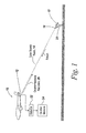
- an aircraft 10 carries a LIDAR unit 12 that includes a search laser to scan the ground with a laser beam 14.
- the laser beam is to operate in the eye-safe region, especially when the LIDAR unit is utilized in populated areas.
- search laser beam It is the purpose of the search laser beam to detect the presence of a seeker 16 at the head of a shoulder-launched missile 18 carried by an individual 20 such that the presence of the seeker is detected even before the missile leaves its launcher.
- a detector generally illustrated at 22, is utilized, with the output thereof driving a countermeasure unit 24 to transmit countermeasure radiation 26 directly back along the boresight line of the search beam when an event is determined to have occurred.
- This event is the return of the reflected light back along the path of the search beam, with the light illuminating the seeker being reflected by seeker optics and other elements within the seeker back along the same direction as the incoming light beam.
- seekers in general are utilized to scan a given area to search for thermal energy from an aircraft and more particularly the aircraft engines.
- the amount of light returned by the seeker is such that, when the seeker has its optics directly trained on the heat source engine, search laser illumination is reflected by the seeker's optics back along the illuminating beam.
- the seeker is not necessarily a retro-reflective optical element, it functions to return a good portion of the illuminating radiation back towards the source of the illumination when the seeker is pointed at the source of the illumination.
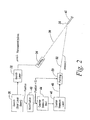
- the LIDAR system includes a search phase 30 in which a search laser 32 is scanned by a pointing system 34 in a direction to cover the surface of the earth underneath the aircraft, either before or after the aircraft.
- the search laser provides an illuminating beam 36 towards seeker 38 of missile 40 which, when a return from the seeker is sensed and a return is identified as illustrated at 42, the position and the identification activates a countermeasure module 44 to activate a countermeasure laser 46 to provide a modulated output 48 to a pointing device 50 which is aligned with pointing device 34 so that countermeasure radiation is transmitted along an intercept line 52 and is made to impinge on seeker 38.
- range gating methods have been utilized to try to distinguish the ground from the seeker, but because the returned pulses are relatively long and because of the slowness of the detection system, range-gated determination is not useful in discriminating ground clutter from an actual target.
- the beam from the seeker usually has a two-degree cone, here illustrated at 54.
- the seeker is looking directly at the LIDAR interrogating laser, and assuming that it is pointed along a center line 56 denoted by zero degrees, then the detected amplitude 58 peaks, for instance, at 1000 au or arbitrary units. It has been found in practice that one gets such a peak return from a seeker only 1% of the time so that looking for peak 60 which requires a direct look of the seeker back at the LIDAR, is a relatively useless way of identifying the presence of a seeker.
- a 1,000-au signal from the seeker might be reduced to a 100-au signal, which at four degrees off axis is a 10-au signal and which, at six degrees off-axis, is a 1 au signal.
- the 1% probability at zero degrees rapidly degrades when the seeker is directly slightly away from the LIDAR.
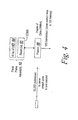
- a focal plane array 62 including an array of detectors 64 and an integrated circuit readout 66 is utilized to determine the position of the seeker.
- the readout integrated circuit which may be integral to the array, is strobed at 100 Hz, meaning that the array has 100 looks per second in order to establish the presence of a seeker aimed at the LIDAR unit.
- the output of the readout integrated circuit is applied to a framer 68, which collects a frame of data, again at 100 frames per second, with a frame correlated to a given search area on the ground. At 100 frames per second, the framer covers the search area in 100 frames if it is to revisit the threat volume once per second.
- FIG. 5 what is depicted is a graph showing the amplitude of returns from the ground in which, for 100 tries, one might obtain a high-peak pulse return 70. However, there will be returns from smaller cross-section targets, such as the ground, anywhere from the first try to the 100th try, as illustrated by lines 72.
- the desired operation is not to look for the large-peak pulse but rather to look for smaller cross-section off-axis pulses from a seeker which occur more frequently than does the large-peak pulse which is the result of the seeker directly aimed at the LIDAR.
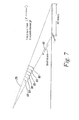
- Ground returns are spread as indicated in Figure 7 . Thus the ability to distinguish short from long pulse returns suppresses ground returns.
- BRDF bidirectional reflectance distribution function
- FIG 8 a top view of the scenario in Figure 7 is illustrated in which the ground is illuminated by a number of lines 90 corresponding to the one-foot interval between the one-nanosecond pulses.
- a seeker 92 is at the position shown, is that there is a return from the seeker, as illustrated 94 on the graph below, whereas the returns from the ground are illustrated at 96.
- the target return will be high but brief, whereas there will be many ground returns from the area in front of and behind the actual target which will be small.
- a short pulse discriminating detector therefore can recognize as an event only a single return in a frame versus the many returns from ground clutter.
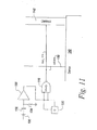
- each of the elements of the array as illustrated in Figure 9 includes a photodiode 100 an RC circuit 102 and 104 coupled to an input 106 of a differential amplifier 108, which serves as a thresholding circuit 110.
- the threshold for which an output pulse is provided from the threshold circuit is set by a signal on line 110.
- the output at 112 indicates that an event has occurred, meaning photons have reached the photo detector at such a high intensity as set by the threshold that an event can be reliably said to have occurred. With the threshold set relatively high, ground returns are rejected.
- threshold circuit 110 is coupled to one input 114 of a NAND gate 116, having as its other input a delayed signal 118 provided by delay circuit 120, which delays the output signal 112 from threshold circuit 110 by, for instance, one nanosecond.
- the particular pixel element in the array will only output a signal 122 when there is radiation on the detector 100 that exists for no more than one nanosecond or whatever the probe pulse length is. If it does, then there will be a signal on input 118 of NAND gate 116 which will prevent the generation of pulse 122. Note that optical aberrations in the target lengthen the pulse but only by a few picoseconds typically.
- an array 128 of such detectors is addressed by rows and columns, respectively 130 and 132, with the cross points of the array being read out in parallel by a direct readout system.
- an event 134 is indicated at a particular point on the array when the threshold 136 has been exceeded.
- an event occurs at array 128 when a threshold has been exceeded. It has been found that, in one scenario, during any one frame in which, for all of the 500-by-500 detectors in the array are read out, only one element will be indicated as having had an event. Thus, while the array may be read out virtually simultaneously for all pixels, at any given time there will only be one event indicated. This means that one can use a direct readout of all elements of the array and detect even a low cross-section target.
- the array can be read out directly, with all pixels of the array being read out in parallel.
- the likelihood that more than one crossover point of the array will indicate a target detected can be made exceedingly low whilst still using low probe laser power and having a high detection probability.
- the probability that an indication from a particular threshold circuit is valid is close to 99%.
- demultiplexing units 140 and 142 are utilized either asynchronously or synchronously to read out all of the pixels of the array grid. This can be done virtually simultaneously in view of standard demultiplexers available operating into the one- to two-gigahertz range. What this means is that all of the pixels of an array can be directly read out by conventional demultiplexers in a time period less than the one-nanosecond pulse spacing.
- each pixel requires a single access line for a row and column.
- Levels can be written to the settable comparator level. Threshold crossings set a register, which in turn puts a signal on the address lines, which are now output lines.
- the two-way capability of the address lines is not essential as the levels can also be set by such techniques as laser scribing a resistive divider to establish the comparison for each pixel.
- the output lines are then sampled in such a way as to detect singlets, doublets, and triplets in any combination on two dimensions, for example a 1x1, a 2x3 or a 2x2.
- the reason for allowing detection of doublets and triplets is to allow for the type of events that can trigger several contiguous pixels. These are the arrival of a return at the intersection of two or four pixels which cause a significant overload. In case of overload, a signal will reach threshold in adjoining pixels. When used with an optic matched to the array the presence of a triplet will indicate overload and therefore effectively extend the single frame dynamic range of the array.
- the range separation can be reduced to that of 0.1 nanosecond or about 3 ⁇ 4 of an inch. This separation prevents use of multiple reflectors hiding the real target. This discrimination limit is determined only by the speed of the laser pulse, the amplifier and the digital logic. This is a significant advantage over trying to achieve the gain on the pixel by the "Geiger mode.” In Geiger mode the detector breaks non-linear producing tremendous gain. The cost is that the fired pixel has to be reset and held off until it has recovered from the event.
- the threshold is set so high that even a single accidental event indication due to comparator/amplifier noise or dark signal fluctuation threshold crossing on the array during a sample is unlikely.
- the sampling rate is set high enough that naturally occurring radiation is also unlikely to reach threshold. This combination of low noise event probability and very short sampling time also makes simultaneous events unlikely in separate groups of pixels. The short time translates to short-range bins due to the finite speed of light.
- the primary event likely to cause a threshold crossing is a short laser pulse return from a compact target.
- a compact target is one that returns a large amount of the signal without significantly stretching the pulse.
- a retro return from an optical sensor is a good example.
- the "gate" time is sufficiently short that this device discriminates against extended bright returns.
- a one-nanosecond sampling time has a two-way length of 15 cm or about 6 inches.
- focal plane arrays will not be paralyzed by a large number of such targets. Since its gate time is of the order of a nanosecond, the targets would have to be within this range tolerance to occur together.
- the subject array supports a frame rate that can be as fast as the time to read the row and column registers.
- this array does not provide intensity data, only threshold crossings although some intensity information can be inferred from the occurrence of doublets and triplets. This is what would be done in most RADAR based detection/acquisition sensors.
- the benefit is a frame rate no longer limited by the need to read the entire array but rather to read a few registers. This approach produces a readout rate several orders of magnitude faster than the current state of the art.
- laser returns from compact sources are highly "scintillated," an effect that produces many orders of magnitude variation over even short ranges. This effect reduces the value of intensity data for ensembles of less than a few hundred samples to nil.
Landscapes
- Engineering & Computer Science (AREA)
- Physics & Mathematics (AREA)
- Radar, Positioning & Navigation (AREA)
- Remote Sensing (AREA)
- General Physics & Mathematics (AREA)
- Computer Networks & Wireless Communication (AREA)
- Electromagnetism (AREA)
- General Engineering & Computer Science (AREA)
- Optics & Photonics (AREA)
- Aviation & Aerospace Engineering (AREA)
- Optical Radar Systems And Details Thereof (AREA)
- Photometry And Measurement Of Optical Pulse Characteristics (AREA)
- Aiming, Guidance, Guns With A Light Source, Armor, Camouflage, And Targets (AREA)
Claims (10)
- Verfahren zum Ignorieren von Bodenstörsignalen beim Bestimmen der Anwesenheit eines Raketensuchers (16, 38, 92), der auftreffendes Licht zurückreflektiert, wobei das Verfahren die folgenden Schritte umfasst:a) Aussenden von ultrakurzen Laserimpulsen (80) mit einer Impulsbreite in der Größenordnung einer Nanosekunde in einen Suchbereich, um den Rückreflektor des Suchers (16, 38, 92) zu beleuchten;b) Detektieren von Rückkehrimpulsen von dem Suchbereich, die die gleiche Impulsbreite wie die ausgesendeten Impulse (80) haben, um so zurückreflektierte Rückkehrimpulse (70, 94) von dem Sucher (16, 38, 92) zu detektieren und um so gedehnte Rückkehrimpulse (72, 90) zurückzuweisen, wobei der Detektionsschritt das Verwenden einer Brennebenenanordnung umfasst, die eine Direktablesungs-Brennebenenanordnung (62) von Photodetektoren (64) besitzt, wobei jeder der Photodetektoren (64) eine Schwellenwertschaltung (110) besitzt, die mit deren Ausgang gekoppelt ist und hoch genug eingestellt ist, um nicht zurückreflektierte Rückkehrimpulse (72, 90) aus dem mit dem Laser beleuchteten Gebiet zu ignorieren;c) direktes und gleichzeitiges Ablesen jedes der Photodetektoren (64) für eine direkte Ereignisdetektion von zurückreflektierter Energie, gekennzeichnet durch Impulsbreiten, die die Impulsbreite der ausgesendeten Impulse (80) haben, wobei das Ablesen in einer Zeitperiode erfolgt, die kurz genug ist, um ein Messergebnis von jedem der Photodetektoren (64) zu erhalten, bevor der nächste Rückkehrimpuls ankommt, wobei die Zeitperiode einen Rahmen definiert; undd) Bestimmen aus dem Messergebnis, dass ein von einem Raketensucher (16, 38, 92) zurückreflektierter Rückkehrimpuls vorhanden ist, und der Position hiervon, falls ein Signal von einer einzelnen Schwellenwertschaltung (110) während des Rahmens vorhanden ist und falls das Signal von der einzelnen Schwellenwertschaltung (110) nicht länger als die Impulsbreite des ausgesendeten ultrakurzen Impulses (80) ist, so dass die Impulsbreiten-Schwellenwertunterscheidung zurückreflektierte Rückkehrimpulse (70, 94) auswählt und gedehnte Rückkehrimpulse (72, 90) von dem beleuchteten Gebiet ignoriert.
- Verfahren nach Anspruch 1, wobei der Bestimmungsschritt das Vorsehen eines NAND-Gatters umfasst, wovon ein Eingang mit dem Ausgang der Schwellenwertschaltung gekoppelt ist und der andere Eingang mit einer verzögerten Version des Ausgangs der Schwellenwertschaltung gekoppelt ist.
- Verfahren nach Anspruch 2, wobei kompakte Ziele von Boden-Rückkehrimpulsen dadurch unterschieden werden, dass sichergestellt wird, dass während eines Rahmens nur eine kleine vorgegebene Anzahl von Ausgängen von der Schwellenwertschaltung vorhanden ist.
- Detektorelement zum Ausführen des Verfahrens nach einem der Ansprüche 1 bis 3.
- Detektorelement nach Anspruch 4 für die Verwendung in einer Brennebenenanordnung, die in einem Laserbereichssucher- oder LIDAR-System verwendet wird, das einen Impuls zu einem zurückreflektierenden Ziel aussendet, wobei der Impuls eine Impulsbreite in der Größenordnung einer Nanosekunde hat, wobei das Detektorelement nur auf zurückreflektierte Energie antwortet, in der die Impulsbreite zurückreflektierter Rückkehrimpulse die Breite des ausgesendeten Impulses besitzt, um so vom Boden zurückkehrende Störsignale zu ignorieren, das Folgendes umfasst: einen Photodetektor; eine Schwellenwertschaltung, die mit dem Photodetektor gekoppelt ist; und ein Filter, das mit der Schwellenwertschaltung gekoppelt ist, um einen Ausgang von dem Photodetektor, der die vorgegebene Nanosekunden-Impulsbreite des ausgesendeten Impulses überschreitet, zu ignorieren, um dadurch wahlweise nur Rückkehrimpulse von dem zurückreflektierenden Ziel zu detektieren.
- Detektorelement nach Anspruch 5, wobei das Filter eine RC-Schaltung umfasst, die eingestellt ist, um Ausgänge von der Schwellenwertschaltung herauszufiltern, die länger dauern als die Zeitdauer der vorgegebenen Nanosekunden-Impulsbreite.
- Detektorelement nach Anspruch 5, wobei das Filter ein NAND-Gatter umfasst, wovon ein Eingang mit dem Ausgang der Schwellenwertschaltung gekoppelt ist und wobei eine Verzögerungsschaltung zwischen den Ausgang der Schwellenwertschaltung und den anderen der Eingänge des NAND-Gatters geschaltet ist.
- Detektorelement nach Anspruch 7, wobei die Verzögerungsschaltung den Ausgang des Schwellenwertdetektors im Nanosekundenbereich verzögert.
- Brennebenenanordnung, die dafür ausgelegt ist, das Verfahren nach einem der Ansprüche 1 bis 3 auszuführen,
das eine Anordnung eines Detektorelements nach einem der Ansprüche 4 bis 8 umfasst; und
eine Demultiplexierungsschaltung umfasst, um die Schwellenwertschaltungen in einem Zeitrahmen abzulesen, der kleiner ist als die Zeit zwischen zu der Anordnung zurückkehrenden Impulsen, wobei der Demultiplexierer sämtliche Photodetektoren in der Anordnung im Wesentlichen gleichzeitig abliest. - Brennpunktebenen-Anordnungsarchitektur für die Verwendung mit einem gepulsten Laser, der Impulse erzeugt, die eine Impulsbreite in der Größenordnung einer Nanosekunde haben, um nur zurückreflektierte Rückkehrimpulse von einem Raketensucher zu detektieren, um das Verfahren nach einem der Ansprüche 1 bis 3 auszuführen, die Folgendes umfasst:einen Photonendetektor und eine Schwellenwertschaltung für jedes Pixel der Anordnung, um die Möglichkeit einer Photonenzählung bei Infrarot-Wellenlängen zu erhöhen; einen ultraschnellen Rahmenausleser für die Anordnung, der ein direktes, gleichzeitiges Ablesen von Pixeln verwendet; Mittel, die mit dem Rahmenausleser gekoppelt sind, um zurückreflektierende Ziele durch Ignorieren von Boden-Rückkehrimpulsen inhärent zu unterscheiden, wobei die Mittel zum inhärenten Unterscheiden ein Filter umfassen, um Rückkehrimpulse zu ignorieren, die über die Impulsbreite der Impulse von dem Laser hinaus fortbestehen; und Mittel, die mit den Mitteln zum inhärenten Unterscheiden gekoppelt sind, um eine Bereichstorschaltung programmieren zu können.
Applications Claiming Priority (3)
| Application Number | Priority Date | Filing Date | Title |
|---|---|---|---|
| US42749402P | 2002-11-19 | 2002-11-19 | |
| US427494P | 2002-11-19 | ||
| PCT/US2003/037042 WO2004046750A2 (en) | 2002-11-19 | 2003-11-17 | Improved active sensor receiver detector array for countermeasuring shoulder-fired missiles |
Publications (3)
| Publication Number | Publication Date |
|---|---|
| EP1563244A2 EP1563244A2 (de) | 2005-08-17 |
| EP1563244A4 EP1563244A4 (de) | 2011-04-20 |
| EP1563244B1 true EP1563244B1 (de) | 2013-10-02 |
Family
ID=32326544
Family Applications (1)
| Application Number | Title | Priority Date | Filing Date |
|---|---|---|---|
| EP03789839.2A Expired - Lifetime EP1563244B1 (de) | 2002-11-19 | 2003-11-17 | Verbessertesaktivsensor-empfängerdetektorarray für gegenmassnahmen für von der schulterabgeschlossene projektile |
Country Status (4)
| Country | Link |
|---|---|
| US (1) | US7193691B2 (de) |
| EP (1) | EP1563244B1 (de) |
| AU (1) | AU2003294356A1 (de) |
| WO (1) | WO2004046750A2 (de) |
Families Citing this family (24)
| Publication number | Priority date | Publication date | Assignee | Title |
|---|---|---|---|---|
| US6980152B2 (en) | 2003-07-03 | 2005-12-27 | Textron Systems Corporation | Externally cued aircraft warning and defense |
| EP1728068B1 (de) * | 2004-02-26 | 2016-11-02 | BAE SYSTEMS Information and Electronic Systems Integration, Inc. | Verbesserter aktiv-such-sensor und verfahren zur detektion durch verwendung von nichtspiegelnden reflexionen |
| US10101455B1 (en) | 2005-03-08 | 2018-10-16 | Lockheed Martin Corporation | Apparatus utilizing electro-optical/infrared threat warning, proactive and reactive countermeasures |
| IL177304A0 (en) * | 2006-08-06 | 2007-07-04 | Raphael E Levy | A method and system for designating a target and generating target related action |
| US8149392B1 (en) | 2007-03-29 | 2012-04-03 | Bae Systems Information And Electronic Systems Integration Inc. | Method and apparatus for reducing handoff inaccuracies in a countermeasures system |
| US8639394B2 (en) * | 2008-12-01 | 2014-01-28 | Lockheed Martin Corporation | Dynamic optical countermeasures for ground level threats to an aircraft |
| DE102009009698B4 (de) | 2009-02-19 | 2010-11-18 | Eads Deutschland Gmbh | Verfahren zum augensicheren Betreiben eines gepulsten Störlasers in einem DIRCM-System |
| WO2011015175A1 (de) * | 2009-08-07 | 2011-02-10 | Eads Deutschland Gmbh | Verfahren zum augensicheren betreiben eines störlasers in einem dircm-system |
| US20130082183A1 (en) * | 2010-04-20 | 2013-04-04 | Bae Systems Australia Limited | Directed infra-red countermeasure system |
| US20120069321A1 (en) * | 2010-09-22 | 2012-03-22 | Quilligan Gerard T | Imaging device and circuit for same |
| DE102011009459B4 (de) | 2011-01-26 | 2015-08-20 | Diehl Bgt Defence Gmbh & Co. Kg | Verfahren und Vorrichtung zum Abwehren eines angreifenden Flugkörpers |
| US9714815B2 (en) | 2012-06-19 | 2017-07-25 | Lockheed Martin Corporation | Visual disruption network and system, method, and computer program product thereof |
| US9632168B2 (en) | 2012-06-19 | 2017-04-25 | Lockheed Martin Corporation | Visual disruption system, method, and computer program product |
| US9196041B2 (en) | 2013-03-14 | 2015-11-24 | Lockheed Martin Corporation | System, method, and computer program product for indicating hostile fire |
| US9103628B1 (en) | 2013-03-14 | 2015-08-11 | Lockheed Martin Corporation | System, method, and computer program product for hostile fire strike indication |
| US9146251B2 (en) | 2013-03-14 | 2015-09-29 | Lockheed Martin Corporation | System, method, and computer program product for indicating hostile fire |
| EP3128743B1 (de) * | 2014-03-31 | 2025-05-21 | Nikon Corporation | Detektionselement, verriegelungsdetektionsvorrichtung und herstellungsverfahren für detektionselement |
| US10012533B2 (en) | 2016-01-15 | 2018-07-03 | Raytheon Company | Semi-active laser (SAL) receivers and methods of use thereof |
| EP3423865B1 (de) * | 2016-03-01 | 2024-03-06 | Brightway Vision Ltd. | Gesteuerte bildgebungsvorrichtung, system und verfahren |
| ES2798998T3 (es) * | 2016-04-25 | 2020-12-14 | Bae Systems Plc | Integración de sistema |
| US20180128904A1 (en) * | 2016-11-07 | 2018-05-10 | Uber Technologies, Inc. | Lidar scanner with optical amplification |
| EP3726251A1 (de) | 2019-04-18 | 2020-10-21 | Bayerische Motoren Werke Aktiengesellschaft | Konzept zur erfassung einer umgebung mit lidar |
| US11558056B2 (en) | 2020-05-29 | 2023-01-17 | Bae Systems Information And Electronic Systems Integration Inc. | Apparatus and control of a single or multiple sources to fire countermeasure expendables on an aircraft |
| CN111983629B (zh) * | 2020-08-14 | 2024-03-26 | 西安应用光学研究所 | 一种线阵信号目标提取装置及提取方法 |
Family Cites Families (14)
| Publication number | Priority date | Publication date | Assignee | Title |
|---|---|---|---|---|
| US4651332A (en) * | 1972-06-02 | 1987-03-17 | The United States Of America As Represented By The Secretary Of The Navy | Sector scan computer |
| US4659429A (en) * | 1983-08-03 | 1987-04-21 | Cornell Research Foundation, Inc. | Method and apparatus for production and use of nanometer scale light beams |
| US4874238A (en) * | 1986-08-27 | 1989-10-17 | Kajima Corporation | Method and device for measurement with laser beam |
| KR910003460B1 (ko) * | 1987-02-12 | 1991-05-31 | 가부시기가이샤 히다찌세이사꾸쇼 | 광학식 정보기록 장치 |
| JPH08179493A (ja) | 1994-12-22 | 1996-07-12 | Hitachi Ltd | 光露光または転写方法および装置またはそのためのマスク |
| JP2001526771A (ja) * | 1996-04-16 | 2001-12-18 | エム. スンリン,ウィリアム | 材料透過画像形成レーダ |
| US5973316A (en) * | 1997-07-08 | 1999-10-26 | Nec Research Institute, Inc. | Sub-wavelength aperture arrays with enhanced light transmission |
| US6171730B1 (en) * | 1997-11-07 | 2001-01-09 | Canon Kabushiki Kaisha | Exposure method and exposure apparatus |
| JPH11265520A (ja) * | 1998-03-17 | 1999-09-28 | Hitachi Ltd | 近接場光ヘッド、近接場光ヘッドの加工方法および光記録再生装置 |
| US6137566A (en) * | 1999-02-24 | 2000-10-24 | Eoo, Inc. | Method and apparatus for signal processing in a laser radar receiver |
| US6392747B1 (en) * | 1999-06-11 | 2002-05-21 | Raytheon Company | Method and device for identifying an object and determining its location |
| JP3917354B2 (ja) * | 2000-09-12 | 2007-05-23 | 株式会社東芝 | 光プローブ及び光ピックアップ装置 |
| US6522396B1 (en) * | 2002-01-08 | 2003-02-18 | Raytheon Company | Dual mode adaptive threshold architecture for 3-D ladar FPA |
| US6661500B1 (en) * | 2002-03-15 | 2003-12-09 | National Semiconductor Corporation | Integrated range finder and imager |
-
2003
- 2003-11-17 US US10/529,982 patent/US7193691B2/en not_active Expired - Lifetime
- 2003-11-17 EP EP03789839.2A patent/EP1563244B1/de not_active Expired - Lifetime
- 2003-11-17 AU AU2003294356A patent/AU2003294356A1/en not_active Abandoned
- 2003-11-17 WO PCT/US2003/037042 patent/WO2004046750A2/en not_active Ceased
Also Published As
| Publication number | Publication date |
|---|---|
| WO2004046750A2 (en) | 2004-06-03 |
| US20060000987A1 (en) | 2006-01-05 |
| AU2003294356A1 (en) | 2004-06-15 |
| WO2004046750A3 (en) | 2004-08-12 |
| EP1563244A2 (de) | 2005-08-17 |
| EP1563244A4 (de) | 2011-04-20 |
| US7193691B2 (en) | 2007-03-20 |
| AU2003294356A8 (en) | 2004-06-15 |
Similar Documents
| Publication | Publication Date | Title |
|---|---|---|
| EP1563244B1 (de) | Verbessertesaktivsensor-empfängerdetektorarray für gegenmassnahmen für von der schulterabgeschlossene projektile | |
| EP1728068B1 (de) | Verbesserter aktiv-such-sensor und verfahren zur detektion durch verwendung von nichtspiegelnden reflexionen | |
| US6877691B2 (en) | High altitude stripping for threat discrimination | |
| US6864965B2 (en) | Dual-mode focal plane array for missile seekers | |
| US8471705B2 (en) | Method and apparatus for detecting presence of a target object via continuous laser and range of the target object via laser pulse | |
| US6674520B2 (en) | Closed-loop infrared countermeasure system using a high frame rate infrared receiver with nulling sequence | |
| Henriksson | Detection probabilities for photon-counting avalanche photodiodes applied to a laser radar system | |
| US20160209266A1 (en) | Panoramic Laser Warning Receiver | |
| US7916278B2 (en) | Polyspectral rangefinder for close-in target ranging and identification of incoming threats | |
| US5015844A (en) | Optical surveillance sensor apparatus | |
| Steinvall et al. | Photon counting ladar work at FOI, Sweden | |
| Zhang et al. | Research on the detection probability curve characteristics of long-range target based on SPAD array lidar | |
| Rao et al. | Design a long-range near infrared LiDAR imaging system for security and surveillance applications | |
| US20230007979A1 (en) | Lidar with photon-resolving detector | |
| IL168502A (en) | Active sensor receiver detector array for detection and countermeasuring shoulder-fired missiles | |
| Dubois et al. | Detecting laser sources on the battlefield | |
| Hanson et al. | Discriminating interceptor technology program (DITP) laser radar | |
| Steinvall | Review of laser sensing devices and systems | |
| Paleologue | Active infrared systems: possible roles in ballistic missile defense? | |
| Guo et al. | 3D imaging laser radar using Geiger-mode APDs: analysis and experiments | |
| Svedbrand et al. | Optics detection using an avalanche photo diode array and the scanning-slit-method | |
| DE102004040218B4 (de) | Annäherungssensoranordnung | |
| CN119334465B (zh) | 大视场选通单光子探测仪及其视场选通方法 | |
| MARINO et al. | A photon counting 3-D imaging laser radar for advanced discriminating interceptor seekers | |
| EP2232293B1 (de) | System zum stören und beschädigen eines ir-sensors |
Legal Events
| Date | Code | Title | Description |
|---|---|---|---|
| PUAI | Public reference made under article 153(3) epc to a published international application that has entered the european phase |
Free format text: ORIGINAL CODE: 0009012 |
|
| 17P | Request for examination filed |
Effective date: 20050429 |
|
| AK | Designated contracting states |
Kind code of ref document: A2 Designated state(s): AT BE BG CH CY CZ DE DK EE ES FI FR GB GR HU IE IT LI LU MC NL PT RO SE SI SK TR |
|
| AX | Request for extension of the european patent |
Extension state: AL LT LV MK |
|
| RIC1 | Information provided on ipc code assigned before grant |
Ipc: 7G 01J 5/02 B Ipc: 7F 41G 7/00 A Ipc: 7G 01B 11/26 B Ipc: 7G 01R 29/02 B |
|
| DAX | Request for extension of the european patent (deleted) | ||
| A4 | Supplementary search report drawn up and despatched |
Effective date: 20110323 |
|
| 17Q | First examination report despatched |
Effective date: 20110926 |
|
| REG | Reference to a national code |
Ref country code: DE Ref legal event code: R079 Ref document number: 60345033 Country of ref document: DE Free format text: PREVIOUS MAIN CLASS: F41G0007000000 Ipc: G01S0017020000 |
|
| GRAP | Despatch of communication of intention to grant a patent |
Free format text: ORIGINAL CODE: EPIDOSNIGR1 |
|
| RIC1 | Information provided on ipc code assigned before grant |
Ipc: G01S 7/486 20060101ALI20130619BHEP Ipc: G01S 17/02 20060101AFI20130619BHEP Ipc: G01S 3/784 20060101ALI20130619BHEP Ipc: G01S 7/487 20060101ALI20130619BHEP Ipc: G01S 7/495 20060101ALI20130619BHEP Ipc: G01S 7/48 20060101ALI20130619BHEP Ipc: G01S 17/66 20060101ALI20130619BHEP |
|
| INTG | Intention to grant announced |
Effective date: 20130718 |
|
| GRAS | Grant fee paid |
Free format text: ORIGINAL CODE: EPIDOSNIGR3 |
|
| GRAA | (expected) grant |
Free format text: ORIGINAL CODE: 0009210 |
|
| AK | Designated contracting states |
Kind code of ref document: B1 Designated state(s): AT BE BG CH CY CZ DE DK EE ES FI FR GB GR HU IE IT LI LU MC NL PT RO SE SI SK TR |
|
| REG | Reference to a national code |
Ref country code: GB Ref legal event code: FG4D |
|
| REG | Reference to a national code |
Ref country code: AT Ref legal event code: REF Ref document number: 634871 Country of ref document: AT Kind code of ref document: T Effective date: 20131015 Ref country code: CH Ref legal event code: EP |
|
| REG | Reference to a national code |
Ref country code: IE Ref legal event code: FG4D |
|
| REG | Reference to a national code |
Ref country code: DE Ref legal event code: R096 Ref document number: 60345033 Country of ref document: DE Effective date: 20131128 |
|
| REG | Reference to a national code |
Ref country code: AT Ref legal event code: MK05 Ref document number: 634871 Country of ref document: AT Kind code of ref document: T Effective date: 20131002 |
|
| REG | Reference to a national code |
Ref country code: NL Ref legal event code: VDEP Effective date: 20131002 |
|
| PG25 | Lapsed in a contracting state [announced via postgrant information from national office to epo] |
Ref country code: SI Free format text: LAPSE BECAUSE OF FAILURE TO SUBMIT A TRANSLATION OF THE DESCRIPTION OR TO PAY THE FEE WITHIN THE PRESCRIBED TIME-LIMIT Effective date: 20131002 |
|
| PG25 | Lapsed in a contracting state [announced via postgrant information from national office to epo] |
Ref country code: CZ Free format text: LAPSE BECAUSE OF FAILURE TO SUBMIT A TRANSLATION OF THE DESCRIPTION OR TO PAY THE FEE WITHIN THE PRESCRIBED TIME-LIMIT Effective date: 20131002 Ref country code: BE Free format text: LAPSE BECAUSE OF FAILURE TO SUBMIT A TRANSLATION OF THE DESCRIPTION OR TO PAY THE FEE WITHIN THE PRESCRIBED TIME-LIMIT Effective date: 20131002 Ref country code: FI Free format text: LAPSE BECAUSE OF FAILURE TO SUBMIT A TRANSLATION OF THE DESCRIPTION OR TO PAY THE FEE WITHIN THE PRESCRIBED TIME-LIMIT Effective date: 20131002 Ref country code: NL Free format text: LAPSE BECAUSE OF FAILURE TO SUBMIT A TRANSLATION OF THE DESCRIPTION OR TO PAY THE FEE WITHIN THE PRESCRIBED TIME-LIMIT Effective date: 20131002 Ref country code: SE Free format text: LAPSE BECAUSE OF FAILURE TO SUBMIT A TRANSLATION OF THE DESCRIPTION OR TO PAY THE FEE WITHIN THE PRESCRIBED TIME-LIMIT Effective date: 20131002 |
|
| PG25 | Lapsed in a contracting state [announced via postgrant information from national office to epo] |
Ref country code: ES Free format text: LAPSE BECAUSE OF FAILURE TO SUBMIT A TRANSLATION OF THE DESCRIPTION OR TO PAY THE FEE WITHIN THE PRESCRIBED TIME-LIMIT Effective date: 20131002 Ref country code: AT Free format text: LAPSE BECAUSE OF FAILURE TO SUBMIT A TRANSLATION OF THE DESCRIPTION OR TO PAY THE FEE WITHIN THE PRESCRIBED TIME-LIMIT Effective date: 20131002 Ref country code: CY Free format text: LAPSE BECAUSE OF FAILURE TO SUBMIT A TRANSLATION OF THE DESCRIPTION OR TO PAY THE FEE WITHIN THE PRESCRIBED TIME-LIMIT Effective date: 20131002 |
|
| REG | Reference to a national code |
Ref country code: DE Ref legal event code: R119 Ref document number: 60345033 Country of ref document: DE |
|
| PG25 | Lapsed in a contracting state [announced via postgrant information from national office to epo] |
Ref country code: PT Free format text: LAPSE BECAUSE OF FAILURE TO SUBMIT A TRANSLATION OF THE DESCRIPTION OR TO PAY THE FEE WITHIN THE PRESCRIBED TIME-LIMIT Effective date: 20140203 |
|
| REG | Reference to a national code |
Ref country code: CH Ref legal event code: PL |
|
| PG25 | Lapsed in a contracting state [announced via postgrant information from national office to epo] |
Ref country code: EE Free format text: LAPSE BECAUSE OF FAILURE TO SUBMIT A TRANSLATION OF THE DESCRIPTION OR TO PAY THE FEE WITHIN THE PRESCRIBED TIME-LIMIT Effective date: 20131002 Ref country code: MC Free format text: LAPSE BECAUSE OF FAILURE TO SUBMIT A TRANSLATION OF THE DESCRIPTION OR TO PAY THE FEE WITHIN THE PRESCRIBED TIME-LIMIT Effective date: 20131002 Ref country code: CH Free format text: LAPSE BECAUSE OF NON-PAYMENT OF DUE FEES Effective date: 20131130 Ref country code: LI Free format text: LAPSE BECAUSE OF NON-PAYMENT OF DUE FEES Effective date: 20131130 |
|
| PLBE | No opposition filed within time limit |
Free format text: ORIGINAL CODE: 0009261 |
|
| STAA | Information on the status of an ep patent application or granted ep patent |
Free format text: STATUS: NO OPPOSITION FILED WITHIN TIME LIMIT |
|
| REG | Reference to a national code |
Ref country code: FR Ref legal event code: ST Effective date: 20140731 |
|
| REG | Reference to a national code |
Ref country code: IE Ref legal event code: MM4A |
|
| PG25 | Lapsed in a contracting state [announced via postgrant information from national office to epo] |
Ref country code: SK Free format text: LAPSE BECAUSE OF FAILURE TO SUBMIT A TRANSLATION OF THE DESCRIPTION OR TO PAY THE FEE WITHIN THE PRESCRIBED TIME-LIMIT Effective date: 20131002 Ref country code: RO Free format text: LAPSE BECAUSE OF FAILURE TO SUBMIT A TRANSLATION OF THE DESCRIPTION OR TO PAY THE FEE WITHIN THE PRESCRIBED TIME-LIMIT Effective date: 20131002 Ref country code: DE Free format text: LAPSE BECAUSE OF NON-PAYMENT OF DUE FEES Effective date: 20140603 Ref country code: IT Free format text: LAPSE BECAUSE OF FAILURE TO SUBMIT A TRANSLATION OF THE DESCRIPTION OR TO PAY THE FEE WITHIN THE PRESCRIBED TIME-LIMIT Effective date: 20131002 |
|
| 26N | No opposition filed |
Effective date: 20140703 |
|
| REG | Reference to a national code |
Ref country code: DE Ref legal event code: R119 Ref document number: 60345033 Country of ref document: DE Effective date: 20140603 |
|
| PG25 | Lapsed in a contracting state [announced via postgrant information from national office to epo] |
Ref country code: DK Free format text: LAPSE BECAUSE OF FAILURE TO SUBMIT A TRANSLATION OF THE DESCRIPTION OR TO PAY THE FEE WITHIN THE PRESCRIBED TIME-LIMIT Effective date: 20131002 |
|
| PG25 | Lapsed in a contracting state [announced via postgrant information from national office to epo] |
Ref country code: IE Free format text: LAPSE BECAUSE OF NON-PAYMENT OF DUE FEES Effective date: 20131117 |
|
| PG25 | Lapsed in a contracting state [announced via postgrant information from national office to epo] |
Ref country code: FR Free format text: LAPSE BECAUSE OF NON-PAYMENT OF DUE FEES Effective date: 20131202 |
|
| PG25 | Lapsed in a contracting state [announced via postgrant information from national office to epo] |
Ref country code: TR Free format text: LAPSE BECAUSE OF FAILURE TO SUBMIT A TRANSLATION OF THE DESCRIPTION OR TO PAY THE FEE WITHIN THE PRESCRIBED TIME-LIMIT Effective date: 20131002 |
|
| PG25 | Lapsed in a contracting state [announced via postgrant information from national office to epo] |
Ref country code: HU Free format text: LAPSE BECAUSE OF FAILURE TO SUBMIT A TRANSLATION OF THE DESCRIPTION OR TO PAY THE FEE WITHIN THE PRESCRIBED TIME-LIMIT; INVALID AB INITIO Effective date: 20031117 Ref country code: BG Free format text: LAPSE BECAUSE OF FAILURE TO SUBMIT A TRANSLATION OF THE DESCRIPTION OR TO PAY THE FEE WITHIN THE PRESCRIBED TIME-LIMIT Effective date: 20131002 Ref country code: LU Free format text: LAPSE BECAUSE OF NON-PAYMENT OF DUE FEES Effective date: 20131117 |
|
| PG25 | Lapsed in a contracting state [announced via postgrant information from national office to epo] |
Ref country code: GR Free format text: LAPSE BECAUSE OF NON-PAYMENT OF DUE FEES Effective date: 20131002 |
|
| PG25 | Lapsed in a contracting state [announced via postgrant information from national office to epo] |
Ref country code: GR Free format text: LAPSE BECAUSE OF FAILURE TO SUBMIT A TRANSLATION OF THE DESCRIPTION OR TO PAY THE FEE WITHIN THE PRESCRIBED TIME-LIMIT Effective date: 20140103 |
|
| PGFP | Annual fee paid to national office [announced via postgrant information from national office to epo] |
Ref country code: GB Payment date: 20201127 Year of fee payment: 18 |
|
| GBPC | Gb: european patent ceased through non-payment of renewal fee |
Effective date: 20211117 |
|
| PG25 | Lapsed in a contracting state [announced via postgrant information from national office to epo] |
Ref country code: GB Free format text: LAPSE BECAUSE OF NON-PAYMENT OF DUE FEES Effective date: 20211117 |