EP1562280A1 - Inverter device - Google Patents
Inverter device Download PDFInfo
- Publication number
- EP1562280A1 EP1562280A1 EP05001550A EP05001550A EP1562280A1 EP 1562280 A1 EP1562280 A1 EP 1562280A1 EP 05001550 A EP05001550 A EP 05001550A EP 05001550 A EP05001550 A EP 05001550A EP 1562280 A1 EP1562280 A1 EP 1562280A1
- Authority
- EP
- European Patent Office
- Prior art keywords
- motor
- controller
- current
- basis
- current density
- Prior art date
- Legal status (The legal status is an assumption and is not a legal conclusion. Google has not performed a legal analysis and makes no representation as to the accuracy of the status listed.)
- Withdrawn
Links
- 238000004804 winding Methods 0.000 claims abstract description 22
- 239000003507 refrigerant Substances 0.000 claims description 24
- CURLTUGMZLYLDI-UHFFFAOYSA-N Carbon dioxide Chemical compound O=C=O CURLTUGMZLYLDI-UHFFFAOYSA-N 0.000 description 2
- 238000010586 diagram Methods 0.000 description 2
- 230000002159 abnormal effect Effects 0.000 description 1
- 238000004378 air conditioning Methods 0.000 description 1
- 239000003990 capacitor Substances 0.000 description 1
- 229910002092 carbon dioxide Inorganic materials 0.000 description 1
- 239000001569 carbon dioxide Substances 0.000 description 1
- 238000001816 cooling Methods 0.000 description 1
- 230000007613 environmental effect Effects 0.000 description 1
- 239000000446 fuel Substances 0.000 description 1
- 230000002401 inhibitory effect Effects 0.000 description 1
- 230000000630 rising effect Effects 0.000 description 1
Images

Classifications
-
- H—ELECTRICITY
- H02—GENERATION; CONVERSION OR DISTRIBUTION OF ELECTRIC POWER
- H02M—APPARATUS FOR CONVERSION BETWEEN AC AND AC, BETWEEN AC AND DC, OR BETWEEN DC AND DC, AND FOR USE WITH MAINS OR SIMILAR POWER SUPPLY SYSTEMS; CONVERSION OF DC OR AC INPUT POWER INTO SURGE OUTPUT POWER; CONTROL OR REGULATION THEREOF
- H02M7/00—Conversion of AC power input into DC power output; Conversion of DC power input into AC power output
- H02M7/42—Conversion of DC power input into AC power output without possibility of reversal
- H02M7/44—Conversion of DC power input into AC power output without possibility of reversal by static converters
- H02M7/48—Conversion of DC power input into AC power output without possibility of reversal by static converters using discharge tubes with control electrode or semiconductor devices with control electrode
- H02M7/53—Conversion of DC power input into AC power output without possibility of reversal by static converters using discharge tubes with control electrode or semiconductor devices with control electrode using devices of a triode or transistor type requiring continuous application of a control signal
- H02M7/537—Conversion of DC power input into AC power output without possibility of reversal by static converters using discharge tubes with control electrode or semiconductor devices with control electrode using devices of a triode or transistor type requiring continuous application of a control signal using semiconductor devices only, e.g. single switched pulse inverters
- H02M7/5387—Conversion of DC power input into AC power output without possibility of reversal by static converters using discharge tubes with control electrode or semiconductor devices with control electrode using devices of a triode or transistor type requiring continuous application of a control signal using semiconductor devices only, e.g. single switched pulse inverters in a bridge configuration
- H02M7/53871—Conversion of DC power input into AC power output without possibility of reversal by static converters using discharge tubes with control electrode or semiconductor devices with control electrode using devices of a triode or transistor type requiring continuous application of a control signal using semiconductor devices only, e.g. single switched pulse inverters in a bridge configuration with automatic control of output voltage or current
-
- H—ELECTRICITY
- H02—GENERATION; CONVERSION OR DISTRIBUTION OF ELECTRIC POWER
- H02P—CONTROL OR REGULATION OF ELECTRIC MOTORS, ELECTRIC GENERATORS OR DYNAMO-ELECTRIC CONVERTERS; CONTROLLING TRANSFORMERS, REACTORS OR CHOKE COILS
- H02P27/00—Arrangements or methods for the control of AC motors characterised by the kind of supply voltage
- H02P27/04—Arrangements or methods for the control of AC motors characterised by the kind of supply voltage using variable-frequency supply voltage, e.g. inverter or converter supply voltage
- H02P27/06—Arrangements or methods for the control of AC motors characterised by the kind of supply voltage using variable-frequency supply voltage, e.g. inverter or converter supply voltage using DC to AC converters or inverters
-
- F—MECHANICAL ENGINEERING; LIGHTING; HEATING; WEAPONS; BLASTING
- F25—REFRIGERATION OR COOLING; COMBINED HEATING AND REFRIGERATION SYSTEMS; HEAT PUMP SYSTEMS; MANUFACTURE OR STORAGE OF ICE; LIQUEFACTION SOLIDIFICATION OF GASES
- F25B—REFRIGERATION MACHINES, PLANTS OR SYSTEMS; COMBINED HEATING AND REFRIGERATION SYSTEMS; HEAT PUMP SYSTEMS
- F25B2600/00—Control issues
- F25B2600/02—Compressor control
- F25B2600/021—Inverters therefor
-
- H—ELECTRICITY
- H02—GENERATION; CONVERSION OR DISTRIBUTION OF ELECTRIC POWER
- H02M—APPARATUS FOR CONVERSION BETWEEN AC AND AC, BETWEEN AC AND DC, OR BETWEEN DC AND DC, AND FOR USE WITH MAINS OR SIMILAR POWER SUPPLY SYSTEMS; CONVERSION OF DC OR AC INPUT POWER INTO SURGE OUTPUT POWER; CONTROL OR REGULATION THEREOF
- H02M1/00—Details of apparatus for conversion
- H02M1/32—Means for protecting converters other than automatic disconnection
-
- H—ELECTRICITY
- H02—GENERATION; CONVERSION OR DISTRIBUTION OF ELECTRIC POWER
- H02M—APPARATUS FOR CONVERSION BETWEEN AC AND AC, BETWEEN AC AND DC, OR BETWEEN DC AND DC, AND FOR USE WITH MAINS OR SIMILAR POWER SUPPLY SYSTEMS; CONVERSION OF DC OR AC INPUT POWER INTO SURGE OUTPUT POWER; CONTROL OR REGULATION THEREOF
- H02M7/00—Conversion of AC power input into DC power output; Conversion of DC power input into AC power output
- H02M7/42—Conversion of DC power input into AC power output without possibility of reversal
- H02M7/44—Conversion of DC power input into AC power output without possibility of reversal by static converters
- H02M7/48—Conversion of DC power input into AC power output without possibility of reversal by static converters using discharge tubes with control electrode or semiconductor devices with control electrode
- H02M7/53—Conversion of DC power input into AC power output without possibility of reversal by static converters using discharge tubes with control electrode or semiconductor devices with control electrode using devices of a triode or transistor type requiring continuous application of a control signal
- H02M7/537—Conversion of DC power input into AC power output without possibility of reversal by static converters using discharge tubes with control electrode or semiconductor devices with control electrode using devices of a triode or transistor type requiring continuous application of a control signal using semiconductor devices only, e.g. single switched pulse inverters
- H02M7/5387—Conversion of DC power input into AC power output without possibility of reversal by static converters using discharge tubes with control electrode or semiconductor devices with control electrode using devices of a triode or transistor type requiring continuous application of a control signal using semiconductor devices only, e.g. single switched pulse inverters in a bridge configuration
- H02M7/53871—Conversion of DC power input into AC power output without possibility of reversal by static converters using discharge tubes with control electrode or semiconductor devices with control electrode using devices of a triode or transistor type requiring continuous application of a control signal using semiconductor devices only, e.g. single switched pulse inverters in a bridge configuration with automatic control of output voltage or current
- H02M7/53875—Conversion of DC power input into AC power output without possibility of reversal by static converters using discharge tubes with control electrode or semiconductor devices with control electrode using devices of a triode or transistor type requiring continuous application of a control signal using semiconductor devices only, e.g. single switched pulse inverters in a bridge configuration with automatic control of output voltage or current with analogue control of three-phase output
- H02M7/53876—Conversion of DC power input into AC power output without possibility of reversal by static converters using discharge tubes with control electrode or semiconductor devices with control electrode using devices of a triode or transistor type requiring continuous application of a control signal using semiconductor devices only, e.g. single switched pulse inverters in a bridge configuration with automatic control of output voltage or current with analogue control of three-phase output based on synthesising a desired voltage vector via the selection of appropriate fundamental voltage vectors, and corresponding dwelling times
Definitions
- the present invention relates to an inverter device for generating a pseudo alternating current by switching a direct current to drive a motor.
- an air conditioner for a vehicle
- a refrigerant is circulated in a refrigerant circuit by an engine-driven compressor to cool the interior of a compartment.
- cars using electric motors such as electric cars, fuel cell powered cars, and hybrid powered automobiles, have been heartily developed.
- an air conditioner uses a battery-driven electromotive compressor.
- the values of the power factor, Vrs, Vuv, and Vdc are necessary. If those values include errors, it is difficult to accurately estimate the secondary current.
- the present invention has been made to solve such a conventional technical problem and is to provide an inverter device capable of realizing exact protection of the winding of a motor.
- An inverter device for generating a pseudo alternating current by switching a direct current to drive a motor, comprises a controller that executes vector control on the basis of a secondary current applied to the motor.
- the controller calculates a current density from the secondary current to execute a predetermined protection operation on the basis of the calculated current density.
- the controller imposes a restriction on an operation frequency of the motor on the basis of the current density.
- the motor drives a compressor of a refrigerant circuit and the controller imposes a restriction on the valve opening of an expansion valve in the refrigerant circuit on the basis of the current density.
- the controller changes the protection operation on the basis of an index that influences the temperature of winding of the motor.
- the inverter device for generating a pseudo alternating current by switching a direct current to drive a motor comprises a controller that executes vector control on the basis of a secondary current applied to the motor.
- the controller calculates a current density from the secondary current to execute a predetermined protection operation on the basis of the calculated current density. Therefore, using the secondary current used for vector control, a direct and exact protection operation can be performed from the value of the current flowing in the motor.
- the controller imposes a restriction on the valve opening of an expansion valve in the refrigerant circuit on the basis of the current density, by expanding the valve opening the temperature rise of the winding of the motor can be prevented.
- the protection operation is changed on the basis of an index that influences the temperature of the winding of the motor, for example, if the protection operation is changed so that the restriction on the operation frequency or the restriction on the valve opening is early executed when the temperature of the refrigerant discharged from the compressor of the refrigerant circuit has risen, temperature rise of the winding of the motor can be more suppressed.
- An on-vehicle air conditioner 1 of the embodiment is for air-conditioning, for example, the interior of a compartment of a hybrid powered automobile.
- an electromotive compressor 2 a heat exchanger 4, an expansion valve (electromotive expansion valve) 6, an evaporator 7, and so on, are disposed in order into a loop and connected to each other to constitute a refrigerant circuit.
- the electromotive compressor 2 is controlled in its operation frequency by an inverter main circuit 8 and a controller 9 that constitute an inverter device 10 according to the present invention.
- a refrigerant such as carbon dioxide
- a refrigerant is compressed by a not-shown compressing element in the electromotive compressor 2 and then discharged through the periphery of the motor 3 into the heat exchanger 4.
- the refrigerant radiates heat in the heat exchanger 4, then throttled by the expansion valve 6, flows in the evaporator 7, and evaporates there.
- the refrigerant exhibits a cooling function to cool the interior of the compartment.
- the refrigerant is then sucked in the electromotive compressor 2. This circulation is repeated.
- An output of a temperature sensor 11 for detecting the temperature of the refrigerant immediately after being discharged from the electromotive compressor 2 is input to the controller 9.
- reference numeral 12 denotes a car battery.
- the above-described inverter main circuit 8 is connected to the battery 12 through a protection circuit 13.
- the inverter main circuit 8 is constituted by a plurality of (six in the embodiment) switching element groups.
- a charging capacitor 19 is connected in parallel to the inverter main circuit 8.
- the inverter main circuit 8 generates a three-phase pseudo alternating current (UVW-phase) from a direct current applied through the protection circuit 13, and applies the alternating current to the motor 3.
- UVW-phase three-phase pseudo alternating current
- a secondary current (Iu, Iv) to be applied to the motor 3 is input from the inverter main circuit 8 to the controller 9.
- the controller 9 performs switching of the switching element groups of the inverter main circuit 8 by vector control, and adjusts the frequency of the pseudo alternating current to control the operation (revolution speed) of the motor 3.
- For detecting the secondary current there are a case of using a Hall element and a case of estimation from the shunt resistance.
- the voltage of the battery 12 (primary voltage) is also input to the controller 9.
- the controller 9 calculates the U-phase current density flowing in the winding of the motor 3, from the secondary current (Iu) being used for vector control (the current value is divided by the cross-sectional area of the winding).
- the controller 9 controls the motor 3 to operate at a requested frequency determined from the temperature of the interior of the compartment, the set temperature, and so on (no restriction).
- the controller 9 carries out a restriction of inhibiting the operation frequency of the motor 3 from rising, irrespective of the requested frequency.
- the controller 9 controls the motor 3 so that the operation frequency of the motor 3 is lowered from the current value. Finally, at the time when the U-phase current density rises to a third upper limit value higher than the second upper limit value, the controller 9 controls the motor 3 to stop.
- the controller 9 calculates the current density flowing in the winding of the motor 3, from the secondary current flowing in the motor 3, and adds restrictions to the operation frequency as the current density rises.
- rise of the temperature of the winding of the motor 3 can be avoided before it happens, and generation of an inconvenience such as burnout can be prevented.
- the controller 9 lowers each of the above-described upper limit values, and thereby changes the protection operation so that the restrictions to the operation frequency may be early started. Because that refrigerant temperature is the temperature of the refrigerant having flowed on the periphery of the motor 3 in the electromotive compressor 2, the refrigerant temperature can be used as an index that influences the temperature of the winding of the motor 3. That is, it is estimated from rise of the refrigerant temperature that the actual temperature of the winding of the motor 3 has risen. Therefore, by detecting the rise of the actual temperature of the winding and changing the protection operation so that it can be early started, protection of the winding can be performed more surely.
- the controller 9 calculates the U-phase current density flowing in the winding of the motor 3, from the secondary current (Iu) being used for vector control.
- the controller 9 adjusts the valve opening of the expansion valve 6 to a requested expansion valve opening determined from the temperature of the interior of the compartment, the set temperature, the temperature of each part of the refrigerant circuit, and so on.
- the controller 9 expands the valve opening of the expansion valve 6 by a predetermined number of steps, irrespective of the requested expansion valve opening.
- the controller 9 calculates the current density flowing in the winding of the motor 3, from the secondary current flowing in the motor 3, and adds a restriction to the control to throttle the valve opening of the expansion valve 6 when the current density has risen.
- the controller 9 lowers the above-described upper limit value, and thereby changes the protection operation so that the expansion of the valve opening of the expansion valve 6 may be early started.
- the present invention is applied to an on-vehicle air conditioner for an automobile.
- the present invention is not limited to that.
- the present invention is effective for various apparatus in which the frequency of a motor is controlled with an inverter, such as an air conditioner for a home.
Landscapes
- Engineering & Computer Science (AREA)
- Power Engineering (AREA)
- Control Of Ac Motors In General (AREA)
- Inverter Devices (AREA)
- Air Conditioning Control Device (AREA)
- Electric Propulsion And Braking For Vehicles (AREA)
Abstract
An object is to provide an inverter device capable
of realizing exact protection of the winding of a motor.
An inverter device for generating a pseudo alternating
current by switching a direct current to drive a motor,
comprises a controller that executes vector control on the
basis of a secondary current applied to the motor. The
controller calculates a current density from the secondary
current to execute a predetermined protection operation on
the basis of the calculated current density. The
controller imposes a restriction on the operation frequency
of the motor on the basis of the current density.
Description
- The present invention relates to an inverter device for generating a pseudo alternating current by switching a direct current to drive a motor.
- Conventionally, for example, in an air conditioner for a vehicle, a refrigerant is circulated in a refrigerant circuit by an engine-driven compressor to cool the interior of a compartment. However, attendant upon recent conspicuousness of environmental problems, cars using electric motors, such as electric cars, fuel cell powered cars, and hybrid powered automobiles, have been heartily developed. In such a car, because electric power is supplied from a battery to a main electric motor to run, an air conditioner uses a battery-driven electromotive compressor.
- In that case, actually, a direct current from a battery is converted into a three-phase pseudo alternating current by an inverter including a plurality of switching element groups and then applied to a motor of an electromotive compressor to drive. However, if a surplus current flows in the winding of the motor, inconvenience such as burnout may arise. Thus, protection of the motor must be intended. For this reason, in a conventional general air conditioner for a home, the primary current flowing from a power source before entering an inverter is measured to make protection (for example, see Japanese Patent No. 2629664).
- Here, in case of making motor protection using the primary current as described above, the secondary current flowing in the motor was calculated from the primary current as follows. That is, the power consumption is represented by
- Therefore, for obtaining the secondary current, the values of the power factor, Vrs, Vuv, and Vdc are necessary. If those values include errors, it is difficult to accurately estimate the secondary current.
- The present invention has been made to solve such a conventional technical problem and is to provide an inverter device capable of realizing exact protection of the winding of a motor.
- An inverter device according to the present invention for generating a pseudo alternating current by switching a direct current to drive a motor, comprises a controller that executes vector control on the basis of a secondary current applied to the motor. The controller calculates a current density from the secondary current to execute a predetermined protection operation on the basis of the calculated current density.
- In the inverter device according to the present invention, the controller imposes a restriction on an operation frequency of the motor on the basis of the current density.
- In the inverter device according to the present invention, the motor drives a compressor of a refrigerant circuit and the controller imposes a restriction on the valve opening of an expansion valve in the refrigerant circuit on the basis of the current density.
- In the inverter device according to the present invention, the controller changes the protection operation on the basis of an index that influences the temperature of winding of the motor.
- According to the present invention, the inverter device for generating a pseudo alternating current by switching a direct current to drive a motor, comprises a controller that executes vector control on the basis of a secondary current applied to the motor. The controller calculates a current density from the secondary current to execute a predetermined protection operation on the basis of the calculated current density. Therefore, using the secondary current used for vector control, a direct and exact protection operation can be performed from the value of the current flowing in the motor.
- That is, if the controller imposes a restriction on the operation frequency of the motor when the current density obtained from the secondary current has risen, abnormal overheat or the like of the winding due to the rise of the current density can be prevented before it happens.
- In addition, in case that the motor drives a compressor of a refrigerant circuit, if the controller imposes a restriction on the valve opening of an expansion valve in the refrigerant circuit on the basis of the current density, by expanding the valve opening the temperature rise of the winding of the motor can be prevented.
- In addition, if the protection operation is changed on the basis of an index that influences the temperature of the winding of the motor, for example, if the protection operation is changed so that the restriction on the operation frequency or the restriction on the valve opening is early executed when the temperature of the refrigerant discharged from the compressor of the refrigerant circuit has risen, temperature rise of the winding of the motor can be more suppressed.
-
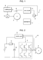
- FIG. 1 is a refrigerant circuit diagram of an on-vehicle air conditioner to which the present invention has been applied;
- FIG. 2 is an electric circuit diagram of an inverter device according to the present invention; and
- FIG. 3 is a graph for explaining a motor winding protection operation of the inverter device of FIG. 2.
-
- Hereinafter, an embodiment of the present invention will be described in detail with reference to the accompanying drawings. An on-vehicle air conditioner 1 of the embodiment is for air-conditioning, for example, the interior of a compartment of a hybrid powered automobile. In the air conditioner 1, an
electromotive compressor 2, aheat exchanger 4, an expansion valve (electromotive expansion valve) 6, anevaporator 7, and so on, are disposed in order into a loop and connected to each other to constitute a refrigerant circuit. Theelectromotive compressor 2 is controlled in its operation frequency by an invertermain circuit 8 and acontroller 9 that constitute aninverter device 10 according to the present invention. - When a
motor 3 of theelectromotive compressor 2 is operated as will be described later, a refrigerant (such as carbon dioxide) is compressed by a not-shown compressing element in theelectromotive compressor 2 and then discharged through the periphery of themotor 3 into theheat exchanger 4. The refrigerant radiates heat in theheat exchanger 4, then throttled by theexpansion valve 6, flows in theevaporator 7, and evaporates there. At this time, the refrigerant exhibits a cooling function to cool the interior of the compartment. The refrigerant is then sucked in theelectromotive compressor 2. This circulation is repeated. An output of atemperature sensor 11 for detecting the temperature of the refrigerant immediately after being discharged from theelectromotive compressor 2 is input to thecontroller 9. - Next, in FIG. 2,
reference numeral 12 denotes a car battery. The above-described invertermain circuit 8 is connected to thebattery 12 through aprotection circuit 13. The invertermain circuit 8 is constituted by a plurality of (six in the embodiment) switching element groups. Acharging capacitor 19 is connected in parallel to the invertermain circuit 8. The invertermain circuit 8 generates a three-phase pseudo alternating current (UVW-phase) from a direct current applied through theprotection circuit 13, and applies the alternating current to themotor 3. - A secondary current (Iu, Iv) to be applied to the
motor 3 is input from the invertermain circuit 8 to thecontroller 9. On the basis of the secondary current, thecontroller 9 performs switching of the switching element groups of the invertermain circuit 8 by vector control, and adjusts the frequency of the pseudo alternating current to control the operation (revolution speed) of themotor 3. For detecting the secondary current, there are a case of using a Hall element and a case of estimation from the shunt resistance. The voltage of the battery 12 (primary voltage) is also input to thecontroller 9. - Next, an example of motor winding protection operation by the
controller 9 will be described with reference to FIG. 3. - The
controller 9 calculates the U-phase current density flowing in the winding of themotor 3, from the secondary current (Iu) being used for vector control (the current value is divided by the cross-sectional area of the winding). When the U-phase current density is not more than a predetermined first upper limit value, thecontroller 9 controls themotor 3 to operate at a requested frequency determined from the temperature of the interior of the compartment, the set temperature, and so on (no restriction). Next, when the U-phase current density exceeds the first upper limit value, thecontroller 9 carries out a restriction of inhibiting the operation frequency of themotor 3 from rising, irrespective of the requested frequency. - Further, when the U-phase current density rises and exceeds a second upper limit value higher than the first upper limit value, the
controller 9 controls themotor 3 so that the operation frequency of themotor 3 is lowered from the current value. Finally, at the time when the U-phase current density rises to a third upper limit value higher than the second upper limit value, thecontroller 9 controls themotor 3 to stop. - As described above, the
controller 9 calculates the current density flowing in the winding of themotor 3, from the secondary current flowing in themotor 3, and adds restrictions to the operation frequency as the current density rises. Thus, rise of the temperature of the winding of themotor 3 can be avoided before it happens, and generation of an inconvenience such as burnout can be prevented. - In addition, on the basis of the output of the
temperature sensor 11, when the temperature of the refrigerant discharged from theelectromotive compressor 2 has risen to a predetermined value, thecontroller 9 lowers each of the above-described upper limit values, and thereby changes the protection operation so that the restrictions to the operation frequency may be early started. Because that refrigerant temperature is the temperature of the refrigerant having flowed on the periphery of themotor 3 in theelectromotive compressor 2, the refrigerant temperature can be used as an index that influences the temperature of the winding of themotor 3. That is, it is estimated from rise of the refrigerant temperature that the actual temperature of the winding of themotor 3 has risen. Therefore, by detecting the rise of the actual temperature of the winding and changing the protection operation so that it can be early started, protection of the winding can be performed more surely. - Next, another example of protection operation by the
controller 9 will be described. Also in this case, thecontroller 9 calculates the U-phase current density flowing in the winding of themotor 3, from the secondary current (Iu) being used for vector control. When the U-phase current density is not more than a predetermined upper limit value, thecontroller 9 adjusts the valve opening of theexpansion valve 6 to a requested expansion valve opening determined from the temperature of the interior of the compartment, the set temperature, the temperature of each part of the refrigerant circuit, and so on. - Next, when the U-phase current density exceeds the upper limit value, the
controller 9 expands the valve opening of theexpansion valve 6 by a predetermined number of steps, irrespective of the requested expansion valve opening. Thus, thecontroller 9 calculates the current density flowing in the winding of themotor 3, from the secondary current flowing in themotor 3, and adds a restriction to the control to throttle the valve opening of theexpansion valve 6 when the current density has risen. By expanding the valve opening, and rise of the temperature of the winding of themotor 3 is avoided before it happens, and generation of an inconvenience such as burnout is prevented. - Also in this case, on the basis of the output of the
temperature sensor 11, when the temperature of the refrigerant discharged from theelectromotive compressor 2 has risen to a predetermined value, thecontroller 9 lowers the above-described upper limit value, and thereby changes the protection operation so that the expansion of the valve opening of theexpansion valve 6 may be early started. - In any of the above-described examples, the present invention is applied to an on-vehicle air conditioner for an automobile. However, the present invention is not limited to that. The present invention is effective for various apparatus in which the frequency of a motor is controlled with an inverter, such as an air conditioner for a home.
Claims (4)
- An inverter device for generating a pseudo alternating current by switching a direct current to drive a motor, the device comprising:a controller that executes vector control on the basis of a secondary current applied to the motor, the controller calculating a current density from the secondary current to execute a predetermined protection operation on the basis of the calculated current density.
- The inverter device according to claim 1, wherein the controller imposes a restriction on an operation frequency of the motor on the basis of the current density.
- The inverter device according to claim 1, wherein the motor drives a compressor of a refrigerant circuit and the controller imposes a restriction on the valve opening of an expansion valve in the refrigerant circuit on the basis of the current density.
- The inverter device according to claim 1, 2, or 3, wherein the controller changes the protection operation on the basis of an index that influences the temperature of winding of the motor.
Applications Claiming Priority (2)
| Application Number | Priority Date | Filing Date | Title |
|---|---|---|---|
| JP2004032211A JP2005224075A (en) | 2004-02-09 | 2004-02-09 | Inverter device |
| JP2004032211 | 2004-02-09 |
Publications (1)
| Publication Number | Publication Date |
|---|---|
| EP1562280A1 true EP1562280A1 (en) | 2005-08-10 |
Family
ID=34675589
Family Applications (1)
| Application Number | Title | Priority Date | Filing Date |
|---|---|---|---|
| EP05001550A Withdrawn EP1562280A1 (en) | 2004-02-09 | 2005-01-26 | Inverter device |
Country Status (4)
| Country | Link |
|---|---|
| US (1) | US7109680B2 (en) |
| EP (1) | EP1562280A1 (en) |
| JP (1) | JP2005224075A (en) |
| CN (1) | CN1311623C (en) |
Families Citing this family (8)
| Publication number | Priority date | Publication date | Assignee | Title |
|---|---|---|---|---|
| JP2005224075A (en) * | 2004-02-09 | 2005-08-18 | Sanyo Electric Co Ltd | Inverter device |
| JP4297953B2 (en) * | 2007-06-22 | 2009-07-15 | 三洋電機株式会社 | Motor control device and compressor |
| JP4557031B2 (en) * | 2008-03-27 | 2010-10-06 | 株式会社デンソー | Air conditioner for vehicles |
| JP5617211B2 (en) * | 2008-11-04 | 2014-11-05 | 富士電機株式会社 | Inverter unit cooling capacity measurement method |
| JP2014070582A (en) | 2012-09-28 | 2014-04-21 | Toyota Industries Corp | Electric compressor and air conditioner |
| KR101535030B1 (en) * | 2014-07-04 | 2015-07-08 | 현대자동차주식회사 | Control method and system of hybrid electric vehicle |
| US9973129B2 (en) | 2015-06-12 | 2018-05-15 | Trane International Inc. | HVAC components having a variable speed drive with optimized power factor correction |
| JP7388158B2 (en) * | 2019-11-29 | 2023-11-29 | オムロン株式会社 | Processing device and method for determining winding temperature calculation model |
Citations (3)
| Publication number | Priority date | Publication date | Assignee | Title |
|---|---|---|---|---|
| EP0539163A2 (en) * | 1991-10-23 | 1993-04-28 | Mitsubishi Denki Kabushiki Kaisha | Inverter air conditioner |
| EP0599608A2 (en) * | 1992-11-27 | 1994-06-01 | SANYO ELECTRIC Co., Ltd. | Method and apparatus for driving motor |
| WO2001010001A2 (en) * | 1999-08-03 | 2001-02-08 | Siemens Aktiengesellschaft | Demagnetization-protected permanent magnet ship propulsion system |
Family Cites Families (54)
| Publication number | Priority date | Publication date | Assignee | Title |
|---|---|---|---|---|
| US4336001A (en) * | 1978-09-19 | 1982-06-22 | Frick Company | Solid state compressor control system |
| US4494162A (en) * | 1981-10-30 | 1985-01-15 | Harsco Corporation | Starter thermal overload protection system |
| CN1013332B (en) * | 1988-03-06 | 1991-07-24 | 陕西机械学院 | Pulse width modulation inverter control device using microprocessor |
| JPH02187050A (en) * | 1989-01-13 | 1990-07-23 | Hitachi Ltd | Semiconductor integrated circuit device |
| US4977751A (en) * | 1989-12-28 | 1990-12-18 | Thermo King Corporation | Refrigeration system having a modulation valve which also performs function of compressor throttling valve |
| US5054294A (en) * | 1990-09-21 | 1991-10-08 | Carrier Corporation | Compressor discharge temperature control for a variable speed compressor |
| JP2629664B2 (en) | 1991-06-21 | 1997-07-09 | 株式会社富士通ゼネラル | Control method of air conditioner |
| US5222368A (en) * | 1991-07-11 | 1993-06-29 | Thermo King Corporation | Method of operating a transport refigeration unit |
| JPH0670533A (en) * | 1992-08-07 | 1994-03-11 | Toshiba Corp | Linear motor |
| US5713724A (en) * | 1994-11-23 | 1998-02-03 | Coltec Industries Inc. | System and methods for controlling rotary screw compressors |
| JPH08182105A (en) * | 1994-12-21 | 1996-07-12 | Toshiba Corp | Electric car control device |
| JPH0966736A (en) * | 1995-06-23 | 1997-03-11 | Denso Corp | Vehicle air conditioner |
| US5701753A (en) * | 1995-06-26 | 1997-12-30 | Nippondenso Co., Ltd. | Air conditioning apparatus |
| KR0177948B1 (en) * | 1995-09-22 | 1999-05-15 | 구자홍 | Inverter Controller for Brushless DC Motor Control |
| WO1998011663A1 (en) * | 1996-09-13 | 1998-03-19 | Hitachi, Ltd. | Device for controlling induction motor and method of controlling the same |
| JP3382627B2 (en) * | 1997-07-16 | 2003-03-04 | 三菱重工業株式会社 | Motor-driven high-speed rotating body drive control device and model discriminating method used in the drive control device |
| WO1999022138A1 (en) * | 1997-10-28 | 1999-05-06 | Coltec Industries, Inc. | Compressor system and method and control for same |
| JP3465569B2 (en) * | 1998-01-26 | 2003-11-10 | 日産自動車株式会社 | Electric vehicle overload prevention device |
| US6222349B1 (en) * | 1998-05-11 | 2001-04-24 | Satcon Technology Corporation | Temperature feedback control of alternator output power |
| US6254353B1 (en) * | 1998-10-06 | 2001-07-03 | General Electric Company | Method and apparatus for controlling operation of a submersible pump |
| US6198613B1 (en) * | 1998-12-23 | 2001-03-06 | Hamilton Sundstrand Corporation | Method and apparatus for distributing alternating electrical current to motors via a direct current bus |
| US6122153A (en) * | 1999-03-15 | 2000-09-19 | Eaton Corporation | Temperature protection control for a motor starter |
| JP2000287493A (en) * | 1999-03-30 | 2000-10-13 | Matsushita Electric Ind Co Ltd | Motor protection device |
| DE10020981B4 (en) * | 1999-04-30 | 2004-04-29 | International Rectifier Corp., El Segundo | Engine control unit with fault protection circuit |
| US6215261B1 (en) * | 1999-05-21 | 2001-04-10 | General Electric Company | Application specific integrated circuit for controlling power devices for commutating a motor based on the back emf of motor |
| JP2001028893A (en) * | 1999-07-12 | 2001-01-30 | Fanuc Ltd | Motor control device |
| JP4139934B2 (en) * | 1999-09-21 | 2008-08-27 | 株式会社安川電機 | AC motor control method and control apparatus |
| JP2001090570A (en) * | 1999-09-28 | 2001-04-03 | Zexel Valeo Climate Control Corp | Drive control device for hybrid compressor |
| US6229278B1 (en) * | 1999-09-29 | 2001-05-08 | Rockwell Technologies, Llc | Voltage and current limiting method and apparatus for a voltage/frequency drive |
| KR20010075919A (en) * | 2000-01-21 | 2001-08-11 | 구자홍 | Current limit circuit of inverter refrigerator |
| JP4273613B2 (en) * | 2000-03-06 | 2009-06-03 | 株式会社デンソー | Air conditioner |
| US6414455B1 (en) * | 2000-04-03 | 2002-07-02 | Alvin J. Watson | System and method for variable drive pump control |
| EP1148307B1 (en) * | 2000-04-19 | 2004-03-17 | Denso Corporation | Heat-pump water heater |
| JP3644354B2 (en) * | 2000-05-09 | 2005-04-27 | トヨタ自動車株式会社 | Temperature estimation method and apparatus |
| JP4415340B2 (en) * | 2000-06-02 | 2010-02-17 | 株式会社日立産機システム | Screw compression device and operation control method thereof |
| JP3777953B2 (en) * | 2000-06-20 | 2006-05-24 | 株式会社日立製作所 | AC motor drive system |
| JP2002186172A (en) * | 2000-12-14 | 2002-06-28 | Kokusan Denki Co Ltd | Inverter power generator and overload control method thereof |
| US6573675B2 (en) * | 2000-12-27 | 2003-06-03 | Transportation Techniques Llc | Method and apparatus for adaptive energy control of hybrid electric vehicle propulsion |
| JP3598975B2 (en) * | 2001-01-19 | 2004-12-08 | 日産自動車株式会社 | Control device for fuel cell vehicle |
| US6459230B1 (en) * | 2001-02-13 | 2002-10-01 | Rockwell Automation Technologies, Inc. | Method and system for measuring a parameter of motor operation |
| DE10119201A1 (en) * | 2001-04-19 | 2002-10-24 | Bsh Bosch Siemens Hausgeraete | Method for measuring the winding temperature of drive motor e.g. for washing machine, requires measuring current flow through at least one winding of motor |
| JP3914004B2 (en) * | 2001-05-25 | 2007-05-16 | 矢崎総業株式会社 | Overcurrent detection / protection device for semiconductor elements |
| JP3844050B2 (en) * | 2001-07-02 | 2006-11-08 | 株式会社安川電機 | Power converter |
| JP3918148B2 (en) * | 2001-07-24 | 2007-05-23 | 株式会社日立製作所 | Inverter device |
| US20030111976A1 (en) * | 2001-12-13 | 2003-06-19 | Kumar Ajith Kuttannair | Detection of loss of cooling air to traction motors |
| KR100442494B1 (en) * | 2002-02-26 | 2004-07-30 | 엘지산전 주식회사 | Control method and controller for torque of inverter |
| US6800952B2 (en) * | 2002-06-18 | 2004-10-05 | Dana Corporation | Method of protection and fault detection for starter/alternator operating in the starter mode |
| US6809428B1 (en) * | 2002-06-21 | 2004-10-26 | Dana Corporation | Overheat protection of an electrical component of an I.C. engine |
| DE10228824A1 (en) * | 2002-06-27 | 2004-05-19 | Siemens Ag | Method and device for determining a runaway of a speed-controlled, permanently excited synchronous motor |
| DE10236377A1 (en) * | 2002-08-02 | 2004-02-12 | Dr. Johannes Heidenhain Gmbh | Error detection method in a drive device |
| KR100661107B1 (en) * | 2003-03-12 | 2006-12-26 | 미쓰비시덴키 가부시키가이샤 | Electric motor controller |
| JP3851617B2 (en) * | 2003-05-27 | 2006-11-29 | ファナック株式会社 | Motor drive device |
| JP2005224075A (en) * | 2004-02-09 | 2005-08-18 | Sanyo Electric Co Ltd | Inverter device |
| JP4379702B2 (en) * | 2004-02-10 | 2009-12-09 | 株式会社デンソー | Brushless motor control device |
-
2004
- 2004-02-09 JP JP2004032211A patent/JP2005224075A/en active Pending
-
2005
- 2005-01-26 EP EP05001550A patent/EP1562280A1/en not_active Withdrawn
- 2005-02-01 CN CNB2005100064659A patent/CN1311623C/en not_active Expired - Fee Related
- 2005-02-02 US US11/047,697 patent/US7109680B2/en not_active Expired - Fee Related
Patent Citations (3)
| Publication number | Priority date | Publication date | Assignee | Title |
|---|---|---|---|---|
| EP0539163A2 (en) * | 1991-10-23 | 1993-04-28 | Mitsubishi Denki Kabushiki Kaisha | Inverter air conditioner |
| EP0599608A2 (en) * | 1992-11-27 | 1994-06-01 | SANYO ELECTRIC Co., Ltd. | Method and apparatus for driving motor |
| WO2001010001A2 (en) * | 1999-08-03 | 2001-02-08 | Siemens Aktiengesellschaft | Demagnetization-protected permanent magnet ship propulsion system |
Also Published As
| Publication number | Publication date |
|---|---|
| US20050174075A1 (en) | 2005-08-11 |
| JP2005224075A (en) | 2005-08-18 |
| CN1311623C (en) | 2007-04-18 |
| CN1655442A (en) | 2005-08-17 |
| US7109680B2 (en) | 2006-09-19 |
Similar Documents
| Publication | Publication Date | Title |
|---|---|---|
| US11075417B2 (en) | Battery cooling control system | |
| US7767354B2 (en) | Temperature controlling apparatus for battery, vehicle apparatus using the same, and controlling method therefor | |
| KR101824344B1 (en) | Hybrid vehicle and method for controlling same | |
| US6415746B2 (en) | Apparatus and method for controlling duty ratio for cooling fan associated motor of vehicle | |
| JP5884807B2 (en) | Hybrid vehicle | |
| CN102510813B (en) | Air-conditioning system for vehicle | |
| US10507707B2 (en) | Controlling HVAC compressor speed in a vehicle | |
| CN112572099B (en) | vehicle control device | |
| US7621142B2 (en) | Cooling system and hybrid vehicle including cooling system | |
| US7102310B2 (en) | Cooling device of power supply | |
| US12208659B2 (en) | Vehicle and method for controlling vehicle | |
| US20170008375A1 (en) | Preconditioning an Electric Vehicle | |
| CN109476209B (en) | Air conditioner for vehicle | |
| WO2007086231A1 (en) | Cooling fan control device and method | |
| JP5561206B2 (en) | Battery charge control device | |
| US20070186573A1 (en) | Methods of and systems for dual drive HVAC compressor controls in automotive vehicles | |
| JP2002247774A (en) | Vehicle air conditioning charge control device and vehicle battery charge management device | |
| US7109680B2 (en) | Inverter device | |
| JP6958267B2 (en) | car | |
| JP2013193511A (en) | Vehicle control system | |
| JP7215362B2 (en) | In-vehicle refrigeration system | |
| JP2009045964A (en) | Vehicle air conditioner and control method thereof | |
| KR20170054626A (en) | Controllig apparatus of electric compressor and method thereof | |
| JP5708293B2 (en) | Vehicle air conditioner | |
| JP2005218283A (en) | Cooling device for power conversion mechanism mounted on vehicle |
Legal Events
| Date | Code | Title | Description |
|---|---|---|---|
| PUAI | Public reference made under article 153(3) epc to a published international application that has entered the european phase |
Free format text: ORIGINAL CODE: 0009012 |
|
| AK | Designated contracting states |
Kind code of ref document: A1 Designated state(s): AT BE BG CH CY CZ DE DK EE ES FI FR GB GR HU IE IS IT LI LT LU MC NL PL PT RO SE SI SK TR |
|
| AX | Request for extension of the european patent |
Extension state: AL BA HR LV MK YU |
|
| 17P | Request for examination filed |
Effective date: 20051102 |
|
| AKX | Designation fees paid |
Designated state(s): DE FR GB |
|
| STAA | Information on the status of an ep patent application or granted ep patent |
Free format text: STATUS: THE APPLICATION HAS BEEN WITHDRAWN |
|
| 18W | Application withdrawn |
Effective date: 20071026 |