EP1562277A1 - Three-phase ac generator for vehicle - Google Patents
Three-phase ac generator for vehicle Download PDFInfo
- Publication number
- EP1562277A1 EP1562277A1 EP02788603A EP02788603A EP1562277A1 EP 1562277 A1 EP1562277 A1 EP 1562277A1 EP 02788603 A EP02788603 A EP 02788603A EP 02788603 A EP02788603 A EP 02788603A EP 1562277 A1 EP1562277 A1 EP 1562277A1
- Authority
- EP
- European Patent Office
- Prior art keywords
- terminal
- diode
- coil
- phase
- out terminal
- Prior art date
- Legal status (The legal status is an assumption and is not a legal conclusion. Google has not performed a legal analysis and makes no representation as to the accuracy of the status listed.)
- Granted
Links
Images


Classifications
-
- H—ELECTRICITY
- H10—SEMICONDUCTOR DEVICES; ELECTRIC SOLID-STATE DEVICES NOT OTHERWISE PROVIDED FOR
- H10W—GENERIC PACKAGES, INTERCONNECTIONS, CONNECTORS OR OTHER CONSTRUCTIONAL DETAILS OF DEVICES COVERED BY CLASS H10
- H10W90/00—Package configurations
-
- H—ELECTRICITY
- H02—GENERATION; CONVERSION OR DISTRIBUTION OF ELECTRIC POWER
- H02K—DYNAMO-ELECTRIC MACHINES
- H02K11/00—Structural association of dynamo-electric machines with electric components or with devices for shielding, monitoring or protection
- H02K11/04—Structural association of dynamo-electric machines with electric components or with devices for shielding, monitoring or protection for rectification
- H02K11/049—Rectifiers associated with stationary parts, e.g. stator cores
- H02K11/05—Rectifiers associated with casings, enclosures or brackets
-
- H—ELECTRICITY
- H02—GENERATION; CONVERSION OR DISTRIBUTION OF ELECTRIC POWER
- H02K—DYNAMO-ELECTRIC MACHINES
- H02K19/00—Synchronous motors or generators
- H02K19/16—Synchronous generators
- H02K19/36—Structural association of synchronous generators with auxiliary electric devices influencing the characteristic of the generator or controlling the generator, e.g. with impedances or switches
-
- H—ELECTRICITY
- H10—SEMICONDUCTOR DEVICES; ELECTRIC SOLID-STATE DEVICES NOT OTHERWISE PROVIDED FOR
- H10W—GENERIC PACKAGES, INTERCONNECTIONS, CONNECTORS OR OTHER CONSTRUCTIONAL DETAILS OF DEVICES COVERED BY CLASS H10
- H10W70/00—Package substrates; Interposers; Redistribution layers [RDL]
- H10W70/40—Leadframes
- H10W70/481—Leadframes for devices being provided for in groups H10D8/00 - H10D48/00
-
- H—ELECTRICITY
- H02—GENERATION; CONVERSION OR DISTRIBUTION OF ELECTRIC POWER
- H02K—DYNAMO-ELECTRIC MACHINES
- H02K3/00—Details of windings
- H02K3/04—Windings characterised by the conductor shape, form or construction, e.g. with bar conductors
- H02K3/28—Layout of windings or of connections between windings
Definitions
- This invention relates to a three-phase alternating current electric generator for a vehicle mounted to the vehicle and used to charge a battery mounted to the vehicle and supply electricity to other electric loads for the vehicle, and particularly relates to a three-phase alternating current electric generator for a vehicle building-in a rectifier assembly for rectifying an alternating current output of each of generating coils of the three phases.
- a Y-shape connection for connecting the respective generating coils of the three phases in a star shape (Y-shape), and a ⁇ -shape connection for connecting the respective generating coils of the three phases in a delta shape ( ⁇ -shape) are known as the three-phase alternating current electric generator for a vehicle building-in the rectifier assembly of this kind.
- the three-phase alternating current electric generator for a vehicle of the conventional Y-shape connection will be explained.
- the three-phase alternating current electric generator of a neutral output utilization type for rectifying a neutral output of each of the generating coils of the three phases and further increasing the rectifying output is known as the three-phase alternating current electric generator for a vehicle of the Y-shape connection.
- the three-phase alternating current electric generator for a vehicle of this neutral output utilization type is disclosed in Fig. 7 of JP-A-9-19119.
- the three-phase alternating current electric generator for a vehicle of the neutral output utilization type of this kind it is necessary to connect a coil terminal of the neutral side of each of the generating coils of the three phases connected in the Y-shape connection to a neutral diode of the rectifier assemblybuilt in the electric generator.
- Each of the generating coils of the three phases has the three coil terminals on the neutral side in total.
- a diode pair connected to the neutral point is constructed by a positive side diode and a negative side diode, and an anode terminal of the positive side diode and a cathode terminal of the negative side diode are overlapped with each other.
- JP-A-9-19119 discloses a three-phase alternating current electric generator for a vehicle in which the connecting structure of each of the generating coils of the three phases and the rectifier assembly is improved.
- a special circuit substrate shown in the upper portion of Fig. 1 of this prior art is proposed.
- this circuit substrate a circuit pattern is formed on one surface of an insulating property substrate.
- the three coil terminals of the neutral side from each generating coil are connected to each other by the circuit pattern. Accordingly, as a result, the diode pair connected to the neutral point is constructed such that one terminal connected to the above circuit pattern is simply nipped between the anode and cathode terminals of this diode pair. Accordingly, its connecting work is simplified.
- the three-phase alternating current electric generator for a vehicle of the conventional ⁇ -shape connection will next be explained.
- this conventional three-phase alternating current electric generator for a vehicle of this ⁇ -shape connecting type is disclosed in Fig. 1 of JP-A-4-42759.
- this three-phase alternating current electric generator of the ⁇ -shape connection it is necessary to connect two coil terminals from two adjacent generating coils among the respective generating coils of the three phases to each corresponding diode pair of the full-wave rectifier assembly built in the electric generator.
- each diode pair for example, it is necessary to fasten terminals from the two adjacent generating coils together with the anode terminal of the positive side diode and the cathode side terminal of the negative side diode. Accordingly, it is also difficult to make this connection.
- This invention proposes an improved three-phase alternating current electric generator for a vehicle able to simplify the connecting work of the generating coils of the three phases and the diode without increasing the special circuit substrate.
- the three-phase alternating current electric generator for a vehicle in this invention is a three-phase alternating current electric generator for a vehicle includes an A-phase generating coil, a B-phase generating coil and a C-phase generating coil, and a rectifier assembly.
- the A-phase, B-phase and C-phase generating coils are connected in Y-shape connection.
- the rectifier assembly rectifies alternating current outputs of the A-phase, B-phase and C-phase generating coils.
- each of the A-phase, B-phase and C-phase generating coils has a non neutral side coil terminal and a neutral side coil terminal.
- the rectifier assembly has a neutral diode for making neutral point connection, and the neutral diode has a first, second and third connecting terminals commonly connected to each other.
- the neutral side coil terminal of the A-phase generating coil is connected to the first connecting terminal, and the neutral side coil terminal of the B-phase generating coil is connected to the second connecting terminal, and the neutral side coil terminal of the C-phase generating coil is connected to the third connecting terminal.
- the neutral diode having the first, second and third connecting terminals commonly connected to each other is used in the three-phase alternating current electric generator for a vehicle in this invention.
- the coil terminals of the neutral side of the A-phase, B-phase and C-phase generating coils of the three phases are respectively connected to the first, second and third connecting terminals of the above neutral diode .
- the connecting work of the neutral diode and the coil terminal of the neutral side of each generating coil is simplified.
- the coil terminals of the neutral side of the generating coils of the three phases are respectively connected to the first, second and third connecting terminals of the neutral diode one by one, and the connecting work is simplified. Further, since no special circuit substrate is used, the internal construction of the electric generator can be simplified.
- the three-phase alternating current electric generator for a vehicle in this invention is an another three-phase alternating current electric generator for a vehicle includes an A-phase, B-phase and C-phase generating coils and a rectifier assembly.
- the A-phase, B-phase and C-phase generating coils are connected in ⁇ -shape connection, and each of the A-phase, B-phase and C-phase generating coils has a first coil terminal and a second coil terminal.
- the rectifier assembly rectifiers alternating current outputs of the A-phase, B-phase and C-phase generating coils, and the rectifier assembly has a first, second and third diode pairs.
- each of the first, second and third diode pairs has first and second connecting terminals commonly connected to each other.
- the second coil terminal of the A-phase generating coil is connected to the first connecting terminal of the first diode pair
- the first coil terminal of the B-phase generating coil is connected to the second connecting terminal of the second diode pair
- the second coil terminal of the B-phase generating coil is connected to the second connecting terminal of the second diode pair.
- the first coil terminal of the C-phase generating coil is connected to the second connecting terminal of the second diode pair, and the second coil terminal of the C-phase generating coil is connected to the first connecting terminal of the third diode pair and the first coil terminal of the A-phase generating coil is connected to the second connecting terminal of the third diode pair.
- the rectifier assembly has the first, second and third diode pairs.
- Each of these diode pairs has the first and second connecting terminals commonly connected to each other.
- the coil terminal of the generating coil of each phase is connected to the first and second connecting terminals of the first, second and third diode pairs.
- the connecting work of each generating coil and each diode pair is simplified.
- the first and second coil terminals of the generating coil of each phase are respectively connected to the connecting terminals of each diode pair one by one, and the connecting work is simplified. Further, since no special circuit substrate is used, the internal construction of the electric generator can be simplified.
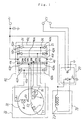
- Fig. 1 is an electric circuit diagram showing a first embodiment of a three-phase alternating current electric generator for a vehicle in this invention.
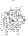
- Fig. 2 is a cross-sectional view showing the three-phase alternating current electric generator for a vehicle in the first embodiment.
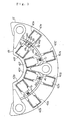
- Fig. 3 is a front view showing a heat sink used in the first embodiment.
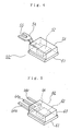
- Fig. 4 is a perspective view showing a non-neutral diode used in the first embodiment.
- Fig. 5 is a perspective view showing a neutral diode used in the first embodiment.
- Fig. 6 is a perspective view showing the connecting structure of a neutral diode pair.
- Fig. 1 is an electric circuit diagram showing a first embodiment of a three-phase alternating current electric generator for a vehicle in this invention.
- Fig. 2 is a cross-sectional view showing the three-phase alternating current electric generator for a vehicle in the first embodiment.
- Fig. 3 is a front view showing a heat sink used in the first embodiment.
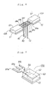
- FIG. 7 is a perspective view showing a neutral diode used in a second embodiment of the three-phase alternating current electric generator for a vehicle in this invention.
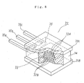
- Fig. 8 is a perspective view showing a neutral diode used in a third embodiment of the three-phase alternating current electric generator for a vehicle in this invention.
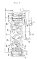
- Fig. 9 is an electric circuit diagram showing a fourth embodiment of the three-phase alternating current electric generator for a vehicle in this invention.
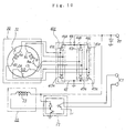
- Fig. 10 is an electric circuit diagram showing a fifth embodiment of the three-phase alternating current electric generator for a vehicle in this invention.
- Fig. 11 is a front view showing a heat sink used in the fifth embodiment.
- Fig. 12 is a perspective view showing a diode used in the fifth embodiment.
- FIG. 13 is a perspective view showing the connecting structure of a diode pair of the fi fth embodiment.
- Fig. 14 is a perspective view showing a diode used in a sixth embodiment of the three-phase alternating current electric generator for a vehicle in this invention.
- Fig. 15 is a perspective view showing the diode used in the three-phase alternating current electric generator for a vehicle in this invention.
- Fig. 1 is an electric circuit diagram showing a first embodiment of a three-phase alternating current electric generator for a vehicle in this invention.
- Fig. 2 is a cross-sectional view showing the internal structure of this three-phase alternating current electric generator for a vehicle.
- the three-phase alternating current electric generator 10 for a vehicle shown in Figs. 1 and 2 is a three-phase alternating current electric generator of a Y-shape connecting type .
- This three-phase alternating current electric generator 10 has a pair of brackets 11, 12, a rotating shaft 13, a rotor 20, a stator 30 and a rectifier 40.
- the rotating shaft 13 is rotatably supported by the pair of brackets 11, 12 through ball bearings 14, 15.
- This rotating shaft 13 is operated by an engine mounted to the vehicle, and the rotor 20 is fixed to this rotating shaft 13.
- This rotor 20 is a rotating field magnet and has a pair of field magnet ion cores 21, 22 and a field magnet coil 23.
- the field magnet coil 23 is magnetized by an unillustrated battery mounted to the vehicle through an electricity supply mechanism 24.
- This electricity supply mechanism 24 has a pair of slip rings 25 arranged in the rotating shaft 13, and a pair of brushes 26 coming in contact with these slip rings 25.
- a field electric current supplied to the field magnet coil 23 is adjusted by a voltage adjuster 27, and the output voltage of the electric generator is adjusted on the basis of the adjustment of this field magnet electric current.
- One end of the field magnet coil 23 is connected to an output terminal OT of the electric generator, and the other end is connected to a common electric potential point (earth) through the voltage adjuster 27.
- the voltage adjuster 27 receives a control signal from a control terminal CT.
- the brush 2 6 and the voltage adjuster 27 are arranged within one bracket 11.
- the stator 30 is arranged around the rotor 20.
- This stator 30 is an armature and has an armature iron core 31 and an armature coil 32.
- the armature iron core 31 is nipped and supported by a fastening bolt 33 between the pair of brackets 11, 12.
- the armature coil 32 has generating coils A, B, C of the respective three phases. These electricity generating coils A, B, C are formed such that both coil terminals of each generating coil are respectively independent.
- These generating coils A, B, C respectively have coil terminals A1, B1, C1 of the non-neutral side and coil terminals A2, B2, C2 of the neutral side.
- the coil terminals A2, B2, C2 of the neutral side of these generating coils A, B, C are connected to each other in the Y-shape connection at a neutral point N, but the line connection at this neutral point N is made by the rectifier assembly 40.
- the rectifier assembly 40 is arranged in the inner circumference of the bracket 11 together with the brush 26 of the electricity supply mechanism 24.
- This rectifier assembly 40 is a three-phase full-wave rectifier.
- This three-phase full-wave rectifier assembly 40 is constructed so as to connect the generating coils A, B, C in the Y-shape connection and full-wave-rectify these outputs and also full-wave-rectify an alternating current output from the neutral point N in order to further increase the output of the electric generator.
- This rectifier assembly 40 has four diode pairs 41A, 41B, 41C, 41N.
- Each of the three diode pairs 41A, 41B, 41C is constructed by a diode 42P of the positive side and a diode 42N of the negative side.
- the diode pair 41N is a diode pair for making the neutral point connection, and is constructed by a neutral diode 43P of the positive side and a neutral diode 43N of the negative side.
- the four diodes of the positive side i.e., the three positive side diodes 42P and the neutral diode 43P of the positive side are respectively attached to a heat sink 44 of the positive side.
- This heat sink 44 of the positive side constitutes a positive side output terminal of the rectifier assembly 40, and is set to a positive side output terminal OT of the electric generator.
- the three negative side diodes 42N and the neutral diode 43N of the negative side are respectively attached to a heat sink 45 of the negative side.
- This heat sink 45 of the negative side constitutes a negative side output terminal of the rectifier assembly 40, and this negative side output terminal is connected to a common electric potential point (earth) .
- the heat sink 45 is directly attached to the inner face of the bracket 11.
- the heat sink 44 is located in the inner circumference of the heat sink 45 and is electrically insulated and attached to the bracket 11.
- the heat sinks 44, 45 are shown in Fig. 3. Both these heat sinks 44, 45 have a horseshoe shape and the heat sink 44 is arranged in the inner circumference of the heat sink 45 as shown in Fig. 3.
- the three positive side diodes 42P and the neutral diode 43P of the positive side are mutually arranged at an equal angle interval.
- the three negative side diodes 42N and the neutral diode 43N of the negative side are mutually arranged at an equal angle interval.
- the three positive side diodes 42P and the three negative side diodes 42N are opposed to each other in the radial direction so that the three diode pairs 41A, 41B, 41C are constructed.
- the neutral diode 43P of the positive side and the neutral diode 43N of the negative side are opposed to each other in the radial direction so that the diode pair 41N connecting the neutral point N is constructed.
- the three positive side diodes 42P and the three negative side diodes 42N mutually have the same package structure 50.
- This package structure 50 is shown by a perspective view in Fig. 4.
- This package structure 50 has an electrically conductive substrate 51, a diode chip 52 brazed onto this electrically conductive substrate 51, a resin package 53 covering this diode chip 52, and a drawing-out terminal 54 drawn out from this resin package 53.
- the tip of this drawing-out terminal 54 is branched into two portions, and a groove 55 is formed between the two portions.
- the cathode electrode of the diode chip 52 is arranged so as to be joined to the electrically conductive substrate 51, and the drawing-out terminal 54 is connected to the anode electrode of the diode chip 52.
- the electrically conductive substrate 51 constitutes a cathode drawing-out terminal
- the drawing-out terminal 54 constitutes an anode drawing-out terminal.
- the anode electrode of the diode chip 52 is arranged so as to be joined to the electrically conductive substrate 51, and the drawing-out terminal 54 is joined to the cathode electrode of the diode chip 52.
- the electrically conductive substrate 51 constitutes an anode drawing-out terminal
- the drawing-out terminal 54 constitutes a cathode drawing-out terminal.
- the electrically conductive substrate 51 of each positive side diode 42P i.e., the cathode drawing-out terminal is joined to the heat sink 44, and the anode drawing-out terminal 54 of each positive side diode 42P is extended toward the negative side diode 42N.
- each negative side diode 42N i.e., the anode drawing-out terminal is joined to the heat sink 45, and the cathode drawing-out terminal 54 of each negative side diode 42N is extended toward the positive side diode 42P.
- the drawing-out terminal 54 of the positive side diode 42P is an anode side terminal
- the drawing-out terminal 54 of the negative side diode 42N is a cathode side terminal.
- These drawing-out terminals 54, 54 are overlapped with each other, and the coil terminals A1, B1, C1 on the non-neutral point side of the respective generating coils A, B, C of the three phases are respectively nipped and brazed between the grooves 55 of these drawing-out terminals 54, 54.
- the positive side diode 43P and the negative side diode 43N constituting the diode pair 41N for the neutral point connection mutually have the same package structure 60.
- This package structure 60 is shown by a perspective view in Fig. 5.
- This package structure 60 has an electrically conductive substrate 61, a diode chip 62 brazed onto this electrically conductive substrate 61, a resin package 63 covering this diode chip 62, and a drawing-out terminal 64 drawn out of this resin package 63.
- This drawing-out terminal 64 has first, second and third connecting terminals 64a, 64b, 64c parallel to each other in the exterior of the resin package 63. These connecting terminals 64a, 64b, 64c are connected to each other within the resin package 63, and are electrically commonly connected to each other.
- the cathode electrode of the diode chip 62 is arranged so as to be joined to the electrically conductive substrate 61, and the drawing-out terminal 64 is connected to the anode electrode of the diode chip 62.
- the electrically conductive substrate 61 constitutes a cathode terminal
- the connecting terminals 64a, 64b, 64c constitute anode terminals.
- the anode electrode of the diode chip 62 is arranged so as to be joined to the electrically conductive substrate 61, and the drawing-out terminal 64 is joined to the cathode electrode of the diode chip 62.
- the electrically conductive substrate 61 constitutes an anode terminal
- the connecting terminals 64a, 64b, 64c constitute cathodes .
- the electrically conductive substrate 51 of the positive side diode 43P i.e., the cathode drawing-out terminal is joined to the heat sink 44, and its anode drawing-out terminal 54 is extended toward the negative side diode 43N.
- the electrically conductive substrate 51 of the negative side diode 43N i.e., the anode drawing-out terminal is joined to the heat sink 45, and its cathode drawing-out terminal 54 is extended toward the positive side diode 42P.
- Fig. 6 is a perspective view showing the connecting structure of the positive side diode 43P and the negative side diode 43N constituting the neutral diode pair 41N, and the neutral side coil terminals A2, B2, C2 of the respective generating coils A, B, C.
- the connecting terminals 64a, 64b, 64c of the positive side diode 43P are extended toward the connecting terminals 64a, 64b, 64c of the negative side diode 43N in parallel with each other.
- the connecting terminals 64a, 64b, 64c of the negative side diode 43N are extended toward the connecting terminals 64a, 64b, 64c of the positive side diode 43P in parallel with each other.
- Fig. 6 is a perspective view showing the connecting structure of the positive side diode 43P and the negative side diode 43N constituting the neutral diode pair 41N, and the neutral side coil terminals A2, B2, C2 of the respective generating coils A, B, C.
- the first, second and third connecting terminals 64a, 64b, 64c of the diode 43P and the first, second and third connecting terminals 64a, 64b, 64c of the diode 43N are arranged such that their tips are butted to each other.
- the coil terminals A2, B2, C2 of the neutral side of the respective generating coils A, B, C are respectively nipped between the tips of the first, second and third connecting terminals 64a, 64b, 64c of the diode 43P and the tips of the first, second and third connecting terminals 64a, 64b, 64c of the diode 43N, and are brazed and fixed to each other in these nipped portions, and are electrically connected.
- the coil terminal A2 of the neutral side of the generating coil A is nipped between the tips of the respective first connecting terminals 64a, 64a of the diodes 43P and 43N, and is brazed.
- the coil terminal B2 of the neutral side of the generating coil B is nipped between the tips of the respective second connecting terminals 64b, 64b of the diodes 43P and 43N, and is brazed.
- the coil terminal C2 of the neutral side of the generating coil C is nipped between the tips of the respective third connecting terminals 64c, 64c of the diodes 43P and 43N, and is brazed.
- the first embodiment relates to the three-phase alternating current electric generator for a vehicle in which the generating coils A, B, C of the three phases are connected in the Y-shape connection.
- the respective generating coils A, B, C are constructed so as to have the coil terminals A1, B1, C1 of the non-neutral side and the coil terminalsA2, B2, C2 of the neutral side.
- the rectifier assembly 40 has the neutral diodes 43P, 43N for making the neutral point connection. These neutral diodes 43P, 43Nhave the first, second and third connecting terminals 64a, 64b, 64c electrically commonly connected to each other.
- the coil terminal A2 of the neutral side of the generating coil A is connected to the first connecting terminal 64a.
- the coil terminal B2 of the neutral side of the generating coil B is connected to the second connecting terminal 64b.
- the coil terminal C2 of the neutral side of the generating coil C is connected to the third connecting terminal 64c.
- One coil terminal of the generating coils A, B, C is connected to each of the connecting terminals 64a, 64b, 64c by this connecting construction so that their connecting work can be easily made. Further, since it is not necessary to use a special circuit substrate as in the conventional case, the interior of the bracket of the electric generator can be simplified.
- the neutral diodes 43P, 43N have the diode chip 62, the resin package 63 for sealing this diode chip 62, and the drawing-out terminal 64 drawn out from this resin package 63.
- the first, second and third connecting terminals 64a, 64b, 64c are formed in this drawing-out terminal 64. Accordingly, the connecting work of the diodes 43P, 43N and the coil terminals A2, B2, C2 of the neutral side of the generating coils A, B, C can be simplified by improving the drawing-out terminal 64.
- the rectifier assembly 40 has the neutral diode 43P of the positive side and the neutral diode 43N of the negative side.
- the anode drawing-out terminal 64 connected to the anode of the diode chip 62 has the first, second and third connecting terminals 64a, 64b, 64c.
- the cathode drawing-out terminal 64 connected to the cathode of the diode chip 62 has the first, second and third connecting terminals 64a, 64b, 64c.
- the coil terminal A2 of the neutral side of the generating coil A is connected to the first connecting terminal 64a of each of the anode drawing-out terminal 64 of the diode 43P of the positive side and the cathode drawing-out terminal 64 of the diode 43N of the negative side.
- the coil terminal B2 of the neutral side of the generating coil B is connected to the second connecting terminal 64b of each of the anode drawing-out terminal 64 of the diode 43P of the positive side and the cathode drawing-out terminal 64 of the diode 43N of the negative side.
- the coil terminal C2 of the neutral side of the generating coil C is connected to the third connecting terminal 64c of each of the anode drawing-out terminal 64 of the diode 43P of the positive side and the cathode drawing-out terminal 64 of the diode 43N of the negative side.
- the coil terminal A2 of the neutral side of the generating coil A is nipped and connected between the respective first connecting terminals 64a of the anode drawing-out terminal 64 of the neutral diode 43P of the positive side and the cathode drawing-out terminal 64 of the neutral diode 43N of the negative side.
- the coil terminal B2 of the neutral side of the generating coil B is nipped and connected between the respective second connecting terminals 64b of the anode drawing-out terminal 64 of the neutral diode 43P of the positive side and the cathode drawing-out terminal 64 of the neutral diode 43N of the negative side.
- the coil terminal C2 of the neutral side of the generating coil C is nipped and connected between the respective third connecting terminals 64b of the anode drawing-out terminal 64 of the neutral diode 43P of the positive side and the cathode drawing-out terminal 64 of the neutral diode 43N of the negative side.
- the connecting work of the coil terminal of the generating coil of each phase and the neutral diodes 43P, 43N is further simplified, the alternating current output at the neutral point of each of the generating coils A, B, C can be rectified and the rectified output canbe increased.
- the package structure 60 shown in Fig. 5 is adopted as the neutral diodes 43P, 43N.
- a package structure 60A shown in Fig. 7 is used as the package structure of the neutral diodes 43P, 43N.
- first, second and third connecting terminals 64a, 64b, 64c are electrically commonly connected to each other in the exterior of a resin package 63 with respect to the drawing-out terminal 64.
- the other constructions of the package structure 60A are the same as the package structure 60 of Fig. 5.
- This package structure 60A of Fig. 7 is also adopted in the neutral diode 43P of the positive side and the neutral diode 43N of the negative side.
- the anode and the cathode of the diode chip 62 are similarly arranged so as to be reverse to each other in the diodes 43P and 43N.
- a composite type neutral diode 70 having a package structure shown in Fig. 8 is used instead of the neutral diodes 43P, 43N of the first embodiment.
- This neutral diode 70 of Fig. 8 is a composite type diode constructed such that the neutral diode 43P of the positive side and the neutral diode 43N of the negative side in the first embodiment are stored into one package.
- a diode pair 41N for making the neutral point connection is constructed by this one composite type diode 70.
- two diode chips 72A, 72B and an intermediate electrically conductive substrate 73 are nipped between a pair of electrically conductive substrates 71A, 71B opposed to each other.
- the intermediate electrically conductive substrate 73 is nipped so as to be located just in an intermediate position of the two diode chips 72A, 72B.
- the diode chip 72A is a diode chip of the positive side, and is arranged between the electrically conductive substrates 71A, 73 such that the cathode is joined to the electrically conductive substrate 71A and the anode is joined to the intermediate electrically conductive substrate 73.
- the diode chip 72B is a diode chip of the negative side, and is arranged between the electrically conductive substrates 73, 71B such that the cathode is joined to the intermediate electrically conductive substrate 73 and the anode is joined to the electrically conductive substrate 71B.
- the diode chips 72A, 72B are sealed by a resin package 74 together with the intermediate electrically conductive substrate 73.
- the electrically conductive substrates 71A, 71B are exposed from the resin package 74.
- a drawing-out terminal 75 drawn out of the resin package 74 is integrally formed in the intermediate electrically conductive substrate 73.
- this drawing-out terminal 75 three connecting terminals 75a, 75b, 75c extended in parallel with each other are formed in the exterior of the resin package 74.
- These connecting terminals 75a, 75b, 75c are electrically commonly connected to each other in the interior of the resin package 74.
- the connecting terminals 75a, 75b, 75c can be also electrically commonly connected to each other in the exterior of the resin package 74.
- the coil terminal A2 of the neutral side of the generating coil A is connected to the first connecting terminal 75a.
- the coil terminal B2 of the neutral side of the generating coil B is connected to the second connecting terminal 75b.
- the coil terminal C2 of the neutral side of the generating coil C is connected to the third connecting terminal 75c.
- the electrically conductive substrate 71B is joined to the heat sink 45 directly attached to the bracket 11.
- the electrically conductive substrate 71A is connected to the heat sink 44 insulated with respect to the bracket 11.
- a three-phase alternating current electric generator for a vehicle having the same electric circuit as Fig. 1 can be constructed by arranging the two heat sinks 44, 45 so as to be opposed to e.g., the rotating shaft 13 in the axial direction and nipping diode pairs 41N, 41A, 41B, 41C constructed by the composite shape diode therebetween.
- the same effects as the first embodiment can be obtained and the diode pairs 41A, 41B, 41C, 41N can be further made compacter.
- Fig. 9 is an electric circuit diagram showing a fourth embodiment of a three-phase alternating current electric generator for a vehicle in this invention.
- two armature coils 32A, 32B are arranged in a stator 30.
- Each of these armature coils 32A, 32B has generating coils A, B, C of three phases connected in a Y-shape connection.
- Each of the respective armature coils 32A, 32B is wound around a common armature iron core 31, and is magnetized by a field magnetic coil 23 of a common rotor 20.
- Two rectifier assemblies 40A, 40B are arranged correspondingly to the two armature coils 32A, 32B.
- the constructions of these rectifier assemblies 40A, 40B are respectively the same as the construction of the rectifier assembly 40 of the first embodiment.
- the rectifier assemblies 40A, 40B are electrically connected to each other in parallel, and are connected to an output terminal OT of the electric generator, and supply electricity to a common battery for a vehicle and an electric load.
- the three-phase alternating current electric generator for a vehicle for connecting the electricity generating coils A, B, C of three phases in the Y-shape connection is used.
- a three-phase alternating current electric generator for a vehicle of a type for connecting the electricity generating coils A, B, C of three phases in a ⁇ -shape connection is used.
- Fig. 10 is an electric circuit diagram showing the fifth embodiment of the three-phase alternating current electric generator for a vehicle in this invention.
- an armature coil 32 of a stator 30 has the generating coils A, B, C of three phases, and each of these generating coils A, B, C is constructed so as to have two independent coil terminals.
- the generating coils A, B, C are respectively set to have first coil terminals A3, B3, C3 and second coil terminals A4, B4, C4.
- a rectifier assembly 40C is combined with these generating coils A, B, C.
- This rectifier assembly 40C is also a three-phase full-wave rectifier, and the electricity generating coils A, B, C are connected in the ⁇ -shape connection.
- the rectifier assembly 40C rectifies the alternating current outputs of the generating coils A, B, C as three-phase full-waves.
- This rectifier assembly 40C has three diode pairs 46A, 46B, 46C. These diode pairs 46A, 46B, 4 6C are mutually equally constructed, and respectively have a diode 47P of the positive side and a diode 47N of the negative side.
- the rectifier assembly 40C has the same heat sinks 44, 45 as the first embodiment.
- Fig. 11 shows the heat sinks 44, 45 used in this fifth embodiment.
- the heat sink 44 of the positive side is arranged within the bracket 11 so as to be located in the inner circumference of the heat sink 45 of the negative side, and is attached to the bracket 11 so as to be electrically insulated from the bracket 11.
- the heat sink 45 is directly attached to the inner face of the bracket 11.
- Three diodes 47P of the positive side are arranged in the heat sink 44 at an equal angle interval.
- Three diodes 47N of the negative side are attached to the heat sink 45 at an equal angle interval so as to be opposed to the diodes 47P of the positive side.
- Diodes mutually having the same package structure 80 are used in the diodes 47P of the positive side and the diodes 47N of the negative side.
- This package structure 80 is shown in Fig. 12.
- This package structure 80 has an electrically conductive substrate 81, a diode chip 82 joined to this electrically conductive substrate 81, and a resin package 83 for sealing this diode chip 82, and a drawing-out terminal 84 drawn out from this resin package 83.
- the diode chip 83 is arranged in the diode 47P of the positive side such that the cathode is joined to the electrically conductive substrate 81 .
- the drawing-out terminal 84 is joined to the anode of the diode 47P of the positive side.
- the electrically conductive substrate 81 constitutes a cathode terminal
- the drawing-out terminal 84 constitutes an anode terminal.
- the diode chip 83 is arranged in the diode 47N of the negative side such that the anode is joined to the electrically conductive substrate 81.
- the drawing-out terminal 84 is joined to the cathode of the diode 47N of the negative side.
- the electrically conductive substrate 81 constitutes an anode terminal and the drawing-out terminal 84 constitutes a cathode terminal.
- their electrically conductive substrates 81 are brazed to the heat sinks 44, 45. Since the electrically conductive substrate 81 is a cathode terminal in the diode 47P of the positive side, the cathode terminals of the three diodes 47P of the positive side are joined to the heat sink 44 as a result. Further, since the electrically conductive substrate 81 is an anode in the diode 47N of the negative side, the anode terminals of the three diodes 47N of the negative side are joined to the heat sink 45 as a result.
- the drawing-out terminal 84 of the package structure 80 has two connecting terminals 84a, 84b in the exterior of the resin package 83. These connecting terminals 84a, 84b are electrically commonly connected to each other within the resin package 83.
- the drawing-out terminal 84 is an anode terminal.
- the drawing-out terminal 84 is a cathode terminal.
- the second coil terminal A4 of the generating coil A is connected between the respective first connecting terminals 84a of the diode 47P of the positive side and the diode 47N of the negative side.
- the first coil terminal B3 of the generating coil B is connected between the respective second connecting terminals 84b of these diodes 47P and 47N.
- the second coil terminal B4 of the generating coil B is connected between the respective first connecting terminals 84a of the diodes 47P, 47N
- the first coil terminal C3 of the generating coil C is connected between the respective second connecting terminals 84b of these diodes 47P, 47N.
- the second coil terminal C4 of the generating coil C is connected between the respective first connecting terminals 84a of the diodes 47P, 47N, and the first coil terminal A3 of the generating coil A is connected between the respective second connecting terminals 84b of the diodes 47P, 47N.
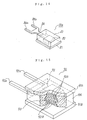
- Fig. 13 shows the connecting structure of the diodes 47P, 47N and the coil terminals A4, B3 of the generating coils with the diode pair 46A as an example.
- the respective first connecting terminals 84a of the diodes 47P, 47N their tips are opposed to each other and the second coil terminal A4 of the generating coil A is nipped and brazed between these tips.
- the respective second connecting terminals 84b of the diodes 47P, 47N the respective tips are opposed to each other and the coil terminal B3 of the generating coil B is nipped and brazed between these tips.
- the other diode pairs 46B, 46C also have similar connecting structures.
- the generating coils A, B, C of three phases are connected in the ⁇ -shape connection by these connecting structures.
- the generating coils A, B, C are respectively constructed so as to have the first coil terminals A3, B3, C3 and the second coil terminals A4, B4, C4.
- the rectifier assembly 40C has the first, second and third diode pairs 46A, 46B, 46C, and these diode pairs 46A, 46B, 46C respectively have the first and second connecting terminals 84a, 84b electrically commonly connected to each other.
- the second coil terminal A4 of the generating coil A is connected to the first connecting terminal 84a of the first diode pair 46A
- the first coil terminal B3 of the generating coil B is connected to the second connecting terminal 84b of the first diode pair 46A.
- the second coil terminal B4 of the generating coil B is connected to the first connecting terminal 84a of the second diode pair 46B, and the first coil terminal C3 of the generating coil C is connected to the second connecting terminal 84b of the second diode pair 46B. Further, the second coil terminal C4 of the generating coil C is connected to the first connecting terminal 84a of the third diode pair 46C, and the first coil terminal A3 of the generating coil A is connected to the second connecting terminal 84b of the third diode pair 46C.
- One coil terminal of the generating coils A, B, C is connected to the first and second connecting terminals 84a, 84b of each of the diode pairs 46A, 46B, 46C as a result by this connecting construction of the fifth embodiment, and their connecting work can be easily made. Further, since it is not necessary to use a special circuit substrate as in the conventional case, the interior of the bracket of the electric generator can be simplified.
- the diode 47P or 47N of the first, second and third diode pairs 46A, 46B, 46C respectively has the diode chip 82, the resin package 83 for sealing this diode chip 82, and the drawing-out terminal 84 drawn out of this resin package 84.
- the first and second connecting terminals 84a, 84b are formed in each of these drawing-out terminals 84. Accordingly, the connecting work of the respective coil terminals A3, A4, B3, B4, C3, C4 of the generating coils A, B, C and the diode 47P or 47N canbe simplified by improving the drawing-out terminal 84.
- each of the diode pairs 46A, 46B, 46C has the positive side diode 47P and the negative side diode 47N.
- the anode drawing-out terminal 84 has the first and second connecting terminals 84a, 84b electrically commonly connected to each other.
- the cathode drawing-out terminal 84 has the first and second connecting terminals 84a, 84b electrically commonly connected to each other.
- the first connecting terminal 84a of the anode drawing-out terminal 84 of the positive side diode 47P and the first connecting terminal 84a of the cathode drawing-out terminal 84 of the negative side diode 47N are connected together with the second coil terminal A4 of the electricity generating coil A.
- the second connecting terminal 84b of the drawing-out terminal 84 of the positive side diode 47P and the second connecting terminal 84b of the drawing-out terminal 84 of the negative side diode 47N in the diode pair 46A are connected together with the first coil terminal B3 of the generating coil B.
- the first connecting terminal 84a of the anode drawing-out terminal 84 of the positive side diode 47P and the first connecting terminal 84a of the cathode drawing-out terminal 84 of the negative side diode 47N are connected together with the second coil terminal B4 of the generating coil B.
- the second connecting terminal 84b of the drawing-out terminal 84 of the positive side diode 47P and the second connecting terminal 84b of the drawing-out terminal 84 of the negative side diode 47N in the second diode pair 46B are connected together with the first coil terminal C3 of the generating coil C.
- the first connecting terminal 84a of the anode drawing-out terminal 84 of the positive side diode 47P and the first connecting terminal 84a of the cathode drawing-out terminal 84 of the negative side diode 47N are connected together with the second coil terminal C4 of the generating coil C.
- the second connecting terminal 84b of the drawing-out terminal 84 of the positive side diode 47P and the second connecting terminal 84b of the drawing-out terminal 84 of the negative side diode 47N in the third diode pair 46C are connected together with the first coil terminal A3 of the generating coil A.
- the respective generating coils A, B, C can be connected in the ⁇ -shape connection by this construction of the fifth embodiment while the connecting work of the coil terminals A3, A4, B3, B4, C3, C4 of the generating coils of the respective phases and the respective diodes 47P, 47N of the diode pairs 46A, 46B, 46C is simplified.
- the second coil terminal A4 of the generating coil A is nipped and connected between the respective first connecting terminals 84a of the positive side diode 47P and the negative side diode 47N.
- the first coil terminal B3 of the generating coil B is nipped and connected between the respective second connecting terminals 84b of the positive side diode 47P and the negative side diode 47N in the first diode pair 46A.
- the second coil terminal B4 of the generating coil B is nipped and connected between the respective first connecting terminals 84a of the positive side diode 47P and the negative side diode 47N.
- first coil terminal C3 of the generating coil C is nipped and connected between the respective second connecting terminals 84b of the positive side diode 47P and the negative side diode 47N in the second diode pair 46B .
- the second coil terminal C4 of the generating coil C is nipped and connected between the respective first connecting terminals 84a of the positive side diode 47P and the negative side diode 47N.
- the first coil terminal A3 of the generating coil A is nipped and connected between the respective second connecting terminals 84b of the positive side diode 47P and the negative side diode 47N in the third diode pair 46C.
- the respective generating coils A, B, C can be connected in the ⁇ -shape connection by this connecting construction while the connecting work of the coil terminals A3, A4, B3, B4, C3, C4 of the generating coils of the respective phases and the respective diodes 47P, 47N of the diode pairs 46A, 46B, 46C is further simplified.
- the package structure 80 shown in Fig. 12 is adopted as the diodes 47P, 47N.
- the package structure 80A shown in Fig. 14 is used as the package structures of the diodes 47P, 47N.
- the first and second connecting terminals 84a, 84b are electrically commonly connected to each other in the exterior of the resin package 83 with respect to the drawing-out terminal 84.
- the other constructions of the package structure 80A are the same as the package structure 80 of Fig. 12.
- This package structure 80A of Fig. 14 is also adopted in the positive side diode 47P and the negative side diode 47N.
- the anode and the cathode of the diode chip 82 are similarly arranged so as to be reverse to each other.
- This seventh embodiment uses a composite type diode 90 having the package structure shown in Fig. 15 instead of the diodes 47P, 47N of the fifth embodiment.
- This diode 90 of Fig. 15 is a composite type diode constructed such that one positive side diode 47P and one negative side diode 47N of the fifth embodiment are stored to one package. Since one diode pair is constructed by this one composite type diode 90, three diode pairs 46A, 46B, 46C are constructed by using three composite type diodes 90 in total.
- two diode chips 92A, 92B and an intermediate electrically conductive substrate 93 are nipped between a pair of electrically conductive substrates 91A, 91B opposed to each other.
- the intermediate electrically conductive substrate 93 is nipped so as to be located just in an intermediate position of the two diode chips 92A, 92B.
- the diode chip 92A is a diode chip of the positive side, and is arranged between the electrically conductive substrates 91A, 93 such that the cathode is joined to the electrically conductive substrate 91A and the anode is joined to the intermediate electrically conductive substrate 93.
- the diode chip 92B is a diode chip of the negative side, and is arranged between the electrically conductive substrates 93, 91B such that the cathode is joined to the intermediate electrically conductive substrate 93 and the anode is joined to the electrically conductive substrate 91B.
- the diode chips 92A, 92B are sealed by a resin package 94 together with the intermediate electrically conductive substrate 93.
- the electrically conductive substrates 91A, 91B are exposed from the resin package 94.
- a drawing-out terminal 95 drawn out of the resin package 94 is integrally formed in the intermediate electrically conductive substrate 93.
- two connecting terminals 95a, 95b extended in parallel with each other are formed in the exterior of the resin package 94.
- These connecting terminals 95a, 95b are electrically commonly connected to each other in the interior of the resin package 94.
- the connecting terminals 95a, 95b can be also electrically commonly connected to each other in the exterior of the resin package 94.
- the second coil terminal A4 of the generating coil A is connected to the first connecting terminal 95a of the composite type diode 90, and the first coil terminal B3 of the generating coil B is connected to the second connecting terminal 95b of the composite type diode 90.
- the second coil terminal B4 of the generating coil B is connected to the first connecting terminal 95a of the composite type diode 90, and the first coil terminal C3 of the generating coil C is connected to the second connecting terminal 95b of the composite type diode 90.
- the second coil terminal C4 of the generating coil C is connected to the first connecting terminal 95a of the composite type diode 90, and the first coil terminal A3 of the generating coil A is connected to the second connecting terminal 95b of the composite type diode 90.
- the electrically conductive substrate 91B is joined to the heat sink 45 directly attached to the bracket 11, and the electrically conductive substrate 91A is connected to the heat sink 44 insulated with respect to the bracket 11.
- a three-phase alternating current electric generator for a vehicle having the same electric circuit as Fig. 1 can be constructed by arranging the two heat sinks 44, 45 so as to be opposed to e.g., the rotating shaft 13 in the axial direction, and nipping the diode pairs 46A, 46B, 46C constructed by the composite type diode 90 between these heat sinks 44, 45.
- the same effects as the fifth embodiment can be obtained, and the diode pairs 46A, 46B, 46C can be further made compacter.
- the three-phase alternating current electric generator for a vehicle in this invention is mounted to various kinds of vehicles such as an automobile, a truck, etc., and is used to charge a battery for a vehicle and supply electricity to other loads for a vehicle.
Landscapes
- Engineering & Computer Science (AREA)
- Power Engineering (AREA)
- Synchronous Machinery (AREA)
- Windings For Motors And Generators (AREA)
Abstract
Description
- This invention relates to a three-phase alternating current electric generator for a vehicle mounted to the vehicle and used to charge a battery mounted to the vehicle and supply electricity to other electric loads for the vehicle, and particularly relates to a three-phase alternating current electric generator for a vehicle building-in a rectifier assembly for rectifying an alternating current output of each of generating coils of the three phases.
- A Y-shape connection for connecting the respective generating coils of the three phases in a star shape (Y-shape), and a Δ-shape connection for connecting the respective generating coils of the three phases in a delta shape (Δ-shape) are known as the three-phase alternating current electric generator for a vehicle building-in the rectifier assembly of this kind.
- First, the three-phase alternating current electric generator for a vehicle of the conventional Y-shape connection will be explained. The three-phase alternating current electric generator of a neutral output utilization type for rectifying a neutral output of each of the generating coils of the three phases and further increasing the rectifying output is known as the three-phase alternating current electric generator for a vehicle of the Y-shape connection. For example, the three-phase alternating current electric generator for a vehicle of this neutral output utilization type is disclosed in Fig. 7 of JP-A-9-19119.
- In the three-phase alternating current electric generator for a vehicle of the neutral output utilization type of this kind, it is necessary to connect a coil terminal of the neutral side of each of the generating coils of the three phases connected in the Y-shape connection to a neutral diode of the rectifier assemblybuilt in the electric generator. Each of the generating coils of the three phases has the three coil terminals on the neutral side in total. In the three-phase alternating current electric generator of the neutral output utilization type, it is necessary to connect all these three coil terminals of the neutral side to one neutral diode.
- In the construction for connecting the three coil terminals of the neutral side to one diode, all the three coil terminals are connected to one connecting terminal of the diode as a result so that it is difficult to make its connecting work.
- For example, in a full-wave rectifier assembly, a diode pair connected to the neutral point is constructed by a positive side diode and a negative side diode, and an anode terminal of the positive side diode and a cathode terminal of the negative side diode are overlapped with each other. However, it is necessary to nip all the three coil terminals of the neutral side terminals from each generating coil in a portion in which these anode terminal and cathode terminal are overlapped with each other and are fastened. It is difficult to make such a connecting work.
- JP-A-9-19119 discloses a three-phase alternating current electric generator for a vehicle in which the connecting structure of each of the generating coils of the three phases and the rectifier assembly is improved. In this prior art, the use of a special circuit substrate shown in the upper portion of Fig. 1 of this prior art is proposed. In this circuit substrate, a circuit pattern is formed on one surface of an insulating property substrate. The three coil terminals of the neutral side from each generating coil are connected to each other by the circuit pattern. Accordingly, as a result, the diode pair connected to the neutral point is constructed such that one terminal connected to the above circuit pattern is simply nipped between the anode and cathode terminals of this diode pair. Accordingly, its connecting work is simplified.
- However, in accordance with this prior art, it is necessary to newly arrange the special circuit substrate between the generating coils of the three phases and the rectifier. This circuit substrate causes an increase in the number of parts built in the electric generator and makes the internal arrangement of a bracket complicated.
- The three-phase alternating current electric generator for a vehicle of the conventional Δ-shape connection will next be explained. For example, this conventional three-phase alternating current electric generator for a vehicle of this Δ-shape connecting type is disclosed in Fig. 1 of JP-A-4-42759.
- In this three-phase alternating current electric generator of the Δ-shape connection, it is necessary to connect two coil terminals from two adjacent generating coils among the respective generating coils of the three phases to each corresponding diode pair of the full-wave rectifier assembly built in the electric generator. In each diode pair, for example, it is necessary to fasten terminals from the two adjacent generating coils together with the anode terminal of the positive side diode and the cathode side terminal of the negative side diode. Accordingly, it is also difficult to make this connection.
- This difficulty can be improved by using a circuit substrate shown in Fig. 1 of JP-A-9-19119. However, the number of parts is increased and the internal structure of the bracket is complicated by using the circuit substrate.
- This invention proposes an improved three-phase alternating current electric generator for a vehicle able to simplify the connecting work of the generating coils of the three phases and the diode without increasing the special circuit substrate.
- The three-phase alternating current electric generator for a vehicle in this invention is a three-phase alternating current electric generator for a vehicle includes an A-phase generating coil, a B-phase generating coil and a C-phase generating coil, and a rectifier assembly. The A-phase, B-phase and C-phase generating coils are connected in Y-shape connection. The rectifier assembly rectifies alternating current outputs of the A-phase, B-phase and C-phase generating coils.
- In the three-phase alternating electric current generator, each of the A-phase, B-phase and C-phase generating coils has a non neutral side coil terminal and a neutral side coil terminal. The rectifier assembly has a neutral diode for making neutral point connection, and the neutral diode has a first, second and third connecting terminals commonly connected to each other. The neutral side coil terminal of the A-phase generating coil is connected to the first connecting terminal, and the neutral side coil terminal of the B-phase generating coil is connected to the second connecting terminal, and the neutral side coil terminal of the C-phase generating coil is connected to the third connecting terminal.
- The neutral diode having the first, second and third connecting terminals commonly connected to each other is used in the three-phase alternating current electric generator for a vehicle in this invention. The coil terminals of the neutral side of the A-phase, B-phase and C-phase generating coils of the three phases are respectively connected to the first, second and third connecting terminals of the above neutral diode . The connecting work of the neutral diode and the coil terminal of the neutral side of each generating coil is simplified. The coil terminals of the neutral side of the generating coils of the three phases are respectively connected to the first, second and third connecting terminals of the neutral diode one by one, and the connecting work is simplified. Further, since no special circuit substrate is used, the internal construction of the electric generator can be simplified.
- Further, the three-phase alternating current electric generator for a vehicle in this invention is an another three-phase alternating current electric generator for a vehicle includes an A-phase, B-phase and C-phase generating coils and a rectifier assembly. The A-phase, B-phase and C-phase generating coils are connected in Δ-shape connection, and each of the A-phase, B-phase and C-phase generating coils has a first coil terminal and a second coil terminal. The rectifier assembly rectifiers alternating current outputs of the A-phase, B-phase and C-phase generating coils, and the rectifier assembly has a first, second and third diode pairs.
- In the another three-phase alternating current electric generator, each of the first, second and third diode pairs has first and second connecting terminals commonly connected to each other. The second coil terminal of the A-phase generating coil is connected to the first connecting terminal of the first diode pair, and the first coil terminal of the B-phase generating coil is connected to the second connecting terminal of the second diode pair and the second coil terminal of the B-phase generating coil is connected to the second connecting terminal of the second diode pair. The first coil terminal of the C-phase generating coil is connected to the second connecting terminal of the second diode pair, and the second coil terminal of the C-phase generating coil is connected to the first connecting terminal of the third diode pair and the first coil terminal of the A-phase generating coil is connected to the second connecting terminal of the third diode pair.
- In the another three-phase alternating current electric generator for a vehicle in this invention, the rectifier assembly has the first, second and third diode pairs. Each of these diode pairs has the first and second connecting terminals commonly connected to each other. The coil terminal of the generating coil of each phase is connected to the first and second connecting terminals of the first, second and third diode pairs. As a result, the connecting work of each generating coil and each diode pair is simplified. The first and second coil terminals of the generating coil of each phase are respectively connected to the connecting terminals of each diode pair one by one, and the connecting work is simplified. Further, since no special circuit substrate is used, the internal construction of the electric generator can be simplified.
- Fig. 1 is an electric circuit diagram showing a first embodiment of a three-phase alternating current electric generator for a vehicle in this invention. Fig. 2 is a cross-sectional view showing the three-phase alternating current electric generator for a vehicle in the first embodiment. Fig. 3 is a front view showing a heat sink used in the first embodiment. Fig. 4 is a perspective view showing a non-neutral diode used in the first embodiment. Fig. 5 is a perspective view showing a neutral diode used in the first embodiment. Fig. 6 is a perspective view showing the connecting structure of a neutral diode pair. Fig. 7 is a perspective view showing a neutral diode used in a second embodiment of the three-phase alternating current electric generator for a vehicle in this invention. Fig. 8 is a perspective view showing a neutral diode used in a third embodiment of the three-phase alternating current electric generator for a vehicle in this invention. Fig. 9 is an electric circuit diagram showing a fourth embodiment of the three-phase alternating current electric generator for a vehicle in this invention. Fig. 10 is an electric circuit diagram showing a fifth embodiment of the three-phase alternating current electric generator for a vehicle in this invention. Fig. 11 is a front view showing a heat sink used in the fifth embodiment. Fig. 12 is a perspective view showing a diode used in the fifth embodiment. Fig. 13 is a perspective view showing the connecting structure of a diode pair of the fi fth embodiment. Fig. 14 is a perspective view showing a diode used in a sixth embodiment of the three-phase alternating current electric generator for a vehicle in this invention. Fig. 15 is a perspective view showing the diode used in the three-phase alternating current electric generator for a vehicle in this invention.
- Fig. 1 is an electric circuit diagram showing a first embodiment of a three-phase alternating current electric generator for a vehicle in this invention. Fig. 2 is a cross-sectional view showing the internal structure of this three-phase alternating current electric generator for a vehicle.
- The three-phase alternating current
electric generator 10 for a vehicle shown in Figs. 1 and 2 is a three-phase alternating current electric generator of a Y-shape connecting type . This three-phase alternating currentelectric generator 10 has a pair ofbrackets 11, 12, a rotatingshaft 13, arotor 20, astator 30 and arectifier 40. The rotatingshaft 13 is rotatably supported by the pair ofbrackets 11, 12 throughball bearings shaft 13 is operated by an engine mounted to the vehicle, and therotor 20 is fixed to this rotatingshaft 13. - This
rotor 20 is a rotating field magnet and has a pair of fieldmagnet ion cores field magnet coil 23. Thefield magnet coil 23 is magnetized by an unillustrated battery mounted to the vehicle through anelectricity supply mechanism 24. Thiselectricity supply mechanism 24 has a pair ofslip rings 25 arranged in therotating shaft 13, and a pair ofbrushes 26 coming in contact with these slip rings 25. A field electric current supplied to thefield magnet coil 23 is adjusted by avoltage adjuster 27, and the output voltage of the electric generator is adjusted on the basis of the adjustment of this field magnet electric current. One end of thefield magnet coil 23 is connected to an output terminal OT of the electric generator, and the other end is connected to a common electric potential point (earth) through thevoltage adjuster 27. Thevoltage adjuster 27 receives a control signal from a control terminal CT. The brush 2 6 and thevoltage adjuster 27 are arranged within one bracket 11. - The
stator 30 is arranged around therotor 20. Thisstator 30 is an armature and has anarmature iron core 31 and anarmature coil 32. Thearmature iron core 31 is nipped and supported by afastening bolt 33 between the pair ofbrackets 11, 12. Thearmature coil 32 has generating coils A, B, C of the respective three phases. These electricity generating coils A, B, C are formed such that both coil terminals of each generating coil are respectively independent. These generating coils A, B, C respectively have coil terminals A1, B1, C1 of the non-neutral side and coil terminals A2, B2, C2 of the neutral side. In the first embodiment shown in Figs. 1 and 2, the coil terminals A2, B2, C2 of the neutral side of these generating coils A, B, C are connected to each other in the Y-shape connection at a neutral point N, but the line connection at this neutral point N is made by therectifier assembly 40. - The
rectifier assembly 40 is arranged in the inner circumference of the bracket 11 together with thebrush 26 of theelectricity supply mechanism 24. Thisrectifier assembly 40 is a three-phase full-wave rectifier. This three-phase full-wave rectifier assembly 40 is constructed so as to connect the generating coils A, B, C in the Y-shape connection and full-wave-rectify these outputs and also full-wave-rectify an alternating current output from the neutral point N in order to further increase the output of the electric generator. - This
rectifier assembly 40 has fourdiode pairs diode pairs diode 42P of the positive side and adiode 42N of the negative side. Thediode pair 41N is a diode pair for making the neutral point connection, and is constructed by aneutral diode 43P of the positive side and aneutral diode 43N of the negative side. - The four diodes of the positive side, i.e., the three
positive side diodes 42P and theneutral diode 43P of the positive side are respectively attached to aheat sink 44 of the positive side. Thisheat sink 44 of the positive side constitutes a positive side output terminal of therectifier assembly 40, and is set to a positive side output terminal OT of the electric generator. Further, the threenegative side diodes 42N and theneutral diode 43N of the negative side are respectively attached to aheat sink 45 of the negative side. Thisheat sink 45 of the negative side constitutes a negative side output terminal of therectifier assembly 40, and this negative side output terminal is connected to a common electric potential point (earth) . Theheat sink 45 is directly attached to the inner face of the bracket 11. Theheat sink 44 is located in the inner circumference of theheat sink 45 and is electrically insulated and attached to the bracket 11. - The heat sinks 44, 45 are shown in Fig. 3. Both these
heat sinks heat sink 44 is arranged in the inner circumference of theheat sink 45 as shown in Fig. 3. In theheat sink 44, the threepositive side diodes 42P and theneutral diode 43P of the positive side are mutually arranged at an equal angle interval. Similarly, in theheat sink 45, the threenegative side diodes 42N and theneutral diode 43N of the negative side are mutually arranged at an equal angle interval. The threepositive side diodes 42P and the threenegative side diodes 42N are opposed to each other in the radial direction so that the threediode pairs neutral diode 43P of the positive side and theneutral diode 43N of the negative side are opposed to each other in the radial direction so that thediode pair 41N connecting the neutral point N is constructed. - The three
positive side diodes 42P and the threenegative side diodes 42N mutually have thesame package structure 50. Thispackage structure 50 is shown by a perspective view in Fig. 4. Thispackage structure 50 has an electricallyconductive substrate 51, adiode chip 52 brazed onto this electricallyconductive substrate 51, aresin package 53 covering thisdiode chip 52, and a drawing-out terminal 54 drawn out from thisresin package 53. The tip of this drawing-outterminal 54 is branched into two portions, and agroove 55 is formed between the two portions. - In the three
positive side diodes 42P, the cathode electrode of thediode chip 52 is arranged so as to be joined to the electricallyconductive substrate 51, and the drawing-outterminal 54 is connected to the anode electrode of thediode chip 52. As its result, in thepositive side diodes 42P, the electricallyconductive substrate 51 constitutes a cathode drawing-out terminal, and the drawing-outterminal 54 constitutes an anode drawing-out terminal. In contrast to this, in the threenegative side diodes 42N, the anode electrode of thediode chip 52 is arranged so as to be joined to the electricallyconductive substrate 51, and the drawing-outterminal 54 is joined to the cathode electrode of thediode chip 52. As its result, in thenegative side diodes 42N, the electricallyconductive substrate 51 constitutes an anode drawing-out terminal, and the drawing-outterminal 54 constitutes a cathode drawing-out terminal. In theheat sink 44 shown in Fig. 3, the electricallyconductive substrate 51 of eachpositive side diode 42P, i.e., the cathode drawing-out terminal is joined to theheat sink 44, and the anode drawing-outterminal 54 of eachpositive side diode 42P is extended toward thenegative side diode 42N. Further, in theheat sink 45, the electricallyconductive substrate 51 of eachnegative side diode 42N, i.e., the anode drawing-out terminal is joined to theheat sink 45, and the cathode drawing-outterminal 54 of eachnegative side diode 42N is extended toward thepositive side diode 42P. - In each of the diode pairs 41A, 41B, 41C, the drawing-out
terminal 54 of thepositive side diode 42P is an anode side terminal, and the drawing-outterminal 54 of thenegative side diode 42N is a cathode side terminal. These drawing-outterminals grooves 55 of these drawing-outterminals - The
positive side diode 43P and thenegative side diode 43N constituting thediode pair 41N for the neutral point connection mutually have thesame package structure 60. Thispackage structure 60 is shown by a perspective view in Fig. 5. Thispackage structure 60 has an electricallyconductive substrate 61, adiode chip 62 brazed onto this electricallyconductive substrate 61, aresin package 63 covering thisdiode chip 62, and a drawing-out terminal 64 drawn out of thisresin package 63. This drawing-outterminal 64 has first, second and third connectingterminals resin package 63. These connectingterminals resin package 63, and are electrically commonly connected to each other. - In the
neutral diode 43P of the positive side, the cathode electrode of thediode chip 62 is arranged so as to be joined to the electricallyconductive substrate 61, and the drawing-outterminal 64 is connected to the anode electrode of thediode chip 62. As its result, in theneutral diode 43P of the positive side, the electricallyconductive substrate 61 constitutes a cathode terminal, and the connectingterminals neutral diode 43N of the negative side, the anode electrode of thediode chip 62 is arranged so as to be joined to the electricallyconductive substrate 61, and the drawing-outterminal 64 is joined to the cathode electrode of thediode chip 62. As its result, in theneutral diode 43N of the negative side, the electricallyconductive substrate 61 constitutes an anode terminal, and the connectingterminals heat sink 44 shown in Fig. 3, the electricallyconductive substrate 51 of thepositive side diode 43P, i.e., the cathode drawing-out terminal is joined to theheat sink 44, and its anode drawing-outterminal 54 is extended toward thenegative side diode 43N. Further, in theheat sink 45, the electricallyconductive substrate 51 of thenegative side diode 43N, i.e., the anode drawing-out terminal is joined to theheat sink 45, and its cathode drawing-outterminal 54 is extended toward thepositive side diode 42P. - Fig. 6 is a perspective view showing the connecting structure of the
positive side diode 43P and thenegative side diode 43N constituting theneutral diode pair 41N, and the neutral side coil terminals A2, B2, C2 of the respective generating coils A, B, C.The connecting terminals positive side diode 43P are extended toward the connectingterminals negative side diode 43N in parallel with each other. Further, the connectingterminals negative side diode 43N are extended toward the connectingterminals positive side diode 43P in parallel with each other. As shown in Fig. 6, the first, second and third connectingterminals diode 43P and the first, second and third connectingterminals diode 43N are arranged such that their tips are butted to each other. The coil terminals A2, B2, C2 of the neutral side of the respective generating coils A, B, C are respectively nipped between the tips of the first, second and third connectingterminals diode 43P and the tips of the first, second and third connectingterminals diode 43N, and are brazed and fixed to each other in these nipped portions, and are electrically connected. The coil terminal A2 of the neutral side of the generating coil A is nipped between the tips of the respective first connectingterminals diodes terminals diodes terminals diodes - As mentioned above, the first embodiment relates to the three-phase alternating current electric generator for a vehicle in which the generating coils A, B, C of the three phases are connected in the Y-shape connection. The respective generating coils A, B, C are constructed so as to have the coil terminals A1, B1, C1 of the non-neutral side and the coil terminalsA2, B2, C2 of the neutral side. Further, the
rectifier assembly 40 has theneutral diodes neutral diodes 43P, 43Nhave the first, second and third connectingterminals terminal 64a. The coil terminal B2 of the neutral side of the generating coil B is connected to the second connectingterminal 64b. The coil terminal C2 of the neutral side of the generating coil C is connected to the third connecting terminal 64c. One coil terminal of the generating coils A, B, C is connected to each of the connectingterminals - In the first embodiment, the
neutral diodes diode chip 62, theresin package 63 for sealing thisdiode chip 62, and the drawing-out terminal 64 drawn out from thisresin package 63. The first, second and third connectingterminals terminal 64. Accordingly, the connecting work of thediodes terminal 64. - In the first embodiment, the
rectifier assembly 40 has theneutral diode 43P of the positive side and theneutral diode 43N of the negative side. In theneutral diode 43P of the positive side, the anode drawing-out terminal 64 connected to the anode of thediode chip 62 has the first, second and third connectingterminals neutral diode 43N of the negative side, the cathode drawing-out terminal 64 connected to the cathode of thediode chip 62 has the first, second and third connectingterminals terminal 64 of thediode 43P of the positive side and the cathode drawing-outterminal 64 of thediode 43N of the negative side. The coil terminal B2 of the neutral side of the generating coil B is connected to the second connecting terminal 64b of each of the anode drawing-outterminal 64 of thediode 43P of the positive side and the cathode drawing-outterminal 64 of thediode 43N of the negative side. The coil terminal C2 of the neutral side of the generating coil C is connected to the third connecting terminal 64c of each of the anode drawing-outterminal 64 of thediode 43P of the positive side and the cathode drawing-outterminal 64 of thediode 43N of the negative side. As this result, while the connecting work of the coil terminal of the generating coil of each phase and theneutral diodes - Further, in the first embodiment, the coil terminal A2 of the neutral side of the generating coil A is nipped and connected between the respective first connecting
terminals 64a of the anode drawing-outterminal 64 of theneutral diode 43P of the positive side and the cathode drawing-outterminal 64 of theneutral diode 43N of the negative side. The coil terminal B2 of the neutral side of the generating coil B is nipped and connected between the respective second connectingterminals 64b of the anode drawing-outterminal 64 of theneutral diode 43P of the positive side and the cathode drawing-outterminal 64 of theneutral diode 43N of the negative side. Further, the coil terminal C2 of the neutral side of the generating coil C is nipped and connected between the respective third connectingterminals 64b of the anode drawing-outterminal 64 of theneutral diode 43P of the positive side and the cathode drawing-outterminal 64 of theneutral diode 43N of the negative side. As its result, while the connecting work of the coil terminal of the generating coil of each phase and theneutral diodes - In the first embodiment, the
package structure 60 shown in Fig. 5 is adopted as theneutral diodes neutral diodes terminals resin package 63 with respect to the drawing-outterminal 64. The other constructions of the package structure 60A are the same as thepackage structure 60 of Fig. 5. This package structure 60A of Fig. 7 is also adopted in theneutral diode 43P of the positive side and theneutral diode 43N of the negative side. The anode and the cathode of thediode chip 62 are similarly arranged so as to be reverse to each other in thediodes - In accordance with this second embodiment, the same effects as the first embodiment can be obtained.
- In this third embodiment, a composite type
neutral diode 70 having a package structure shown in Fig. 8 is used instead of theneutral diodes neutral diode 70 of Fig. 8 is a composite type diode constructed such that theneutral diode 43P of the positive side and theneutral diode 43N of the negative side in the first embodiment are stored into one package. Adiode pair 41N for making the neutral point connection is constructed by this onecomposite type diode 70. - In this
neutral diode 70, twodiode chips conductive substrate 73 are nipped between a pair of electricallyconductive substrates conductive substrate 73 is nipped so as to be located just in an intermediate position of the twodiode chips diode chip 72A is a diode chip of the positive side, and is arranged between the electricallyconductive substrates conductive substrate 71A and the anode is joined to the intermediate electricallyconductive substrate 73. Thediode chip 72B is a diode chip of the negative side, and is arranged between the electricallyconductive substrates conductive substrate 73 and the anode is joined to the electricallyconductive substrate 71B. The diode chips 72A, 72B are sealed by aresin package 74 together with the intermediate electricallyconductive substrate 73. The electricallyconductive substrates resin package 74. - A drawing-out terminal 75 drawn out of the
resin package 74 is integrally formed in the intermediate electricallyconductive substrate 73. In this drawing-out terminal 75, three connectingterminals resin package 74. These connectingterminals resin package 74. However, the connectingterminals resin package 74. - The coil terminal A2 of the neutral side of the generating coil A is connected to the first connecting
terminal 75a. The coil terminal B2 of the neutral side of the generating coil B is connected to the second connecting terminal 75b. The coil terminal C2 of the neutral side of the generating coil C is connected to the third connecting terminal 75c. - The electrically
conductive substrate 71B is joined to theheat sink 45 directly attached to the bracket 11. The electricallyconductive substrate 71A is connected to theheat sink 44 insulated with respect to the bracket 11. If the composite type diode constructed by compounding a positive side diode chip and a negative side diode chip is also used in the diode pairs 41A, 41B, 41C, a three-phase alternating current electric generator for a vehicle having the same electric circuit as Fig. 1 can be constructed by arranging the twoheat sinks shaft 13 in the axial direction and nippingdiode pairs - In this third embodiment, the same effects as the first embodiment can be obtained and the diode pairs 41A, 41B, 41C, 41N can be further made compacter.
- Fig. 9 is an electric circuit diagram showing a fourth embodiment of a three-phase alternating current electric generator for a vehicle in this invention. In this fourth embodiment, two
armature coils stator 30. Each of thesearmature coils respective armature coils armature iron core 31, and is magnetized by a fieldmagnetic coil 23 of acommon rotor 20. - Two
rectifier assemblies armature coils rectifier assemblies rectifier assembly 40 of the first embodiment. Therectifier assemblies - In this fourth embodiment, the same effects as the first embodiment are obtained. In addition to this, electricity can be supplied to various kinds of loads for a vehicle in two systems using the two
armature coils rectifier assemblies - In all the above first to fourth embodiments, the three-phase alternating current electric generator for a vehicle for connecting the electricity generating coils A, B, C of three phases in the Y-shape connection is used. However, in the fifth embodiment, a three-phase alternating current electric generator for a vehicle of a type for connecting the electricity generating coils A, B, C of three phases in a Δ-shape connection is used.
- Fig. 10 is an electric circuit diagram showing the fifth embodiment of the three-phase alternating current electric generator for a vehicle in this invention. In this fifth embodiment, similar to the first embodiment, an
armature coil 32 of astator 30 has the generating coils A, B, C of three phases, and each of these generating coils A, B, C is constructed so as to have two independent coil terminals. In this fifth embodiment, the generating coils A, B, C are respectively set to have first coil terminals A3, B3, C3 and second coil terminals A4, B4, C4. - A
rectifier assembly 40C is combined with these generating coils A, B, C. Thisrectifier assembly 40C is also a three-phase full-wave rectifier, and the electricity generating coils A, B, C are connected in the Δ-shape connection. Therectifier assembly 40C rectifies the alternating current outputs of the generating coils A, B, C as three-phase full-waves. Thisrectifier assembly 40C has threediode pairs diode 47P of the positive side and adiode 47N of the negative side. - The
rectifier assembly 40C has the same heat sinks 44, 45 as the first embodiment. Fig. 11 shows the heat sinks 44, 45 used in this fifth embodiment. Theheat sink 44 of the positive side is arranged within the bracket 11 so as to be located in the inner circumference of theheat sink 45 of the negative side, and is attached to the bracket 11 so as to be electrically insulated from the bracket 11. Theheat sink 45 is directly attached to the inner face of the bracket 11. Threediodes 47P of the positive side are arranged in theheat sink 44 at an equal angle interval. Threediodes 47N of the negative side are attached to theheat sink 45 at an equal angle interval so as to be opposed to thediodes 47P of the positive side. - Diodes mutually having the
same package structure 80 are used in thediodes 47P of the positive side and thediodes 47N of the negative side. Thispackage structure 80 is shown in Fig. 12. Thispackage structure 80 has an electricallyconductive substrate 81, adiode chip 82 joined to this electricallyconductive substrate 81, and aresin package 83 for sealing thisdiode chip 82, and a drawing-out terminal 84 drawn out from thisresin package 83. - The
diode chip 83 is arranged in thediode 47P of the positive side such that the cathode is joined to the electricallyconductive substrate 81 . The drawing-outterminal 84 is joined to the anode of thediode 47P of the positive side. As a result, in thediode 47P of the positive side, the electricallyconductive substrate 81 constitutes a cathode terminal, and the drawing-outterminal 84 constitutes an anode terminal. Thediode chip 83 is arranged in thediode 47N of the negative side such that the anode is joined to the electricallyconductive substrate 81. The drawing-outterminal 84 is joined to the cathode of thediode 47N of the negative side. As a result, in thediode 47N of the negative side, the electricallyconductive substrate 81 constitutes an anode terminal and the drawing-outterminal 84 constitutes a cathode terminal. In both the threediodes 47P of the positive side and the threediodes 47N of the negative side, their electricallyconductive substrates 81 are brazed to the heat sinks 44, 45. Since the electricallyconductive substrate 81 is a cathode terminal in thediode 47P of the positive side, the cathode terminals of the threediodes 47P of the positive side are joined to theheat sink 44 as a result. Further, since the electricallyconductive substrate 81 is an anode in thediode 47N of the negative side, the anode terminals of the threediodes 47N of the negative side are joined to theheat sink 45 as a result. - The drawing-out
terminal 84 of thepackage structure 80 has two connectingterminals resin package 83. These connectingterminals resin package 83. In thediode 47P of the positive side, the drawing-outterminal 84 is an anode terminal. In thediode 47N of the negative side, the drawing-outterminal 84 is a cathode terminal. Thesediodes terminals terminals 84 are opposed to each other. - In the
diode pair 46A, the second coil terminal A4 of the generating coil A is connected between the respective first connectingterminals 84a of thediode 47P of the positive side and thediode 47N of the negative side. The first coil terminal B3 of the generating coil B is connected between the respective second connectingterminals 84b of thesediodes diode pair 46B, the second coil terminal B4 of the generating coil B is connected between the respective first connectingterminals 84a of thediodes terminals 84b of thesediodes diode pair 46C, the second coil terminal C4 of the generating coil C is connected between the respective first connectingterminals 84a of thediodes terminals 84b of thediodes - Fig. 13 shows the connecting structure of the
diodes diode pair 46A as an example. In the respective first connectingterminals 84a of thediodes terminals 84b of thediodes - As mentioned above, in this fifth embodiment, the generating coils A, B, C are respectively constructed so as to have the first coil terminals A3, B3, C3 and the second coil terminals A4, B4, C4. The
rectifier assembly 40C has the first, second and third diode pairs 46A, 46B, 46C, and these diode pairs 46A, 46B, 46C respectively have the first and second connectingterminals first diode pair 46A, and the first coil terminal B3 of the generating coil B is connected to the second connecting terminal 84b of thefirst diode pair 46A. Further, the second coil terminal B4 of the generating coil B is connected to the first connecting terminal 84a of thesecond diode pair 46B, and the first coil terminal C3 of the generating coil C is connected to the second connecting terminal 84b of thesecond diode pair 46B. Further, the second coil terminal C4 of the generating coil C is connected to the first connecting terminal 84a of thethird diode pair 46C, and the first coil terminal A3 of the generating coil A is connected to the second connecting terminal 84b of thethird diode pair 46C. One coil terminal of the generating coils A, B, C is connected to the first and second connectingterminals - Further, in the fifth embodiment, the
diode diode chip 82, theresin package 83 for sealing thisdiode chip 82, and the drawing-out terminal 84 drawn out of thisresin package 84. The first and second connectingterminals terminals 84. Accordingly, the connecting work of the respective coil terminals A3, A4, B3, B4, C3, C4 of the generating coils A, B, C and thediode terminal 84. - Further, in the fifth embodiment, each of the diode pairs 46A, 46B, 46C has the
positive side diode 47P and thenegative side diode 47N. In thepositive side diode 47P, the anode drawing-outterminal 84 has the first and second connectingterminals negative side diode 47N, the cathode drawing-outterminal 84 has the first and second connectingterminals respective diodes - Further, in the fifth embodiment, in the
first diode pair 46A, the second coil terminal A4 of the generating coil A is nipped and connected between the respective first connectingterminals 84a of thepositive side diode 47P and thenegative side diode 47N. Further, the first coil terminal B3 of the generating coil B is nipped and connected between the respective second connectingterminals 84b of thepositive side diode 47P and thenegative side diode 47N in thefirst diode pair 46A. In thesecond diode pair 46B, the second coil terminal B4 of the generating coil B is nipped and connected between the respective first connectingterminals 84a of thepositive side diode 47P and thenegative side diode 47N. Further, the first coil terminal C3 of the generating coil C is nipped and connected between the respective second connectingterminals 84b of thepositive side diode 47P and thenegative side diode 47N in thesecond diode pair 46B . In thethird diode pair 46C, the second coil terminal C4 of the generating coil C is nipped and connected between the respective first connectingterminals 84a of thepositive side diode 47P and thenegative side diode 47N. Further, the first coil terminal A3 of the generating coil A is nipped and connected between the respective second connectingterminals 84b of thepositive side diode 47P and thenegative side diode 47N in thethird diode pair 46C. The respective generating coils A, B, C can be connected in the Δ-shape connection by this connecting construction while the connecting work of the coil terminals A3, A4, B3, B4, C3, C4 of the generating coils of the respective phases and therespective diodes - In the fifth embodiment, the
package structure 80 shown in Fig. 12 is adopted as thediodes package structure 80A shown in Fig. 14 is used as the package structures of thediodes package structure 80A of Fig. 14, the first and second connectingterminals resin package 83 with respect to the drawing-outterminal 84. The other constructions of thepackage structure 80A are the same as thepackage structure 80 of Fig. 12. Thispackage structure 80A of Fig. 14 is also adopted in thepositive side diode 47P and thenegative side diode 47N. In thediodes diode chip 82 are similarly arranged so as to be reverse to each other. - In accordance with this sixth embodiment, the same effects as the fifth embodiment can be obtained.
- This seventh embodiment uses a
composite type diode 90 having the package structure shown in Fig. 15 instead of thediodes diode 90 of Fig. 15 is a composite type diode constructed such that onepositive side diode 47P and onenegative side diode 47N of the fifth embodiment are stored to one package. Since one diode pair is constructed by this onecomposite type diode 90, threediode pairs composite type diodes 90 in total. - In this
composite type diode 90, twodiode chips conductive substrate 93 are nipped between a pair of electricallyconductive substrates 91A, 91B opposed to each other. The intermediate electricallyconductive substrate 93 is nipped so as to be located just in an intermediate position of the twodiode chips diode chip 92A is a diode chip of the positive side, and is arranged between the electricallyconductive substrates conductive substrate 91A and the anode is joined to the intermediate electricallyconductive substrate 93. Thediode chip 92B is a diode chip of the negative side, and is arranged between the electricallyconductive substrates 93, 91B such that the cathode is joined to the intermediate electricallyconductive substrate 93 and the anode is joined to the electrically conductive substrate 91B. The diode chips 92A, 92B are sealed by aresin package 94 together with the intermediate electricallyconductive substrate 93. The electricallyconductive substrates 91A, 91B are exposed from theresin package 94. - A drawing-out terminal 95 drawn out of the
resin package 94 is integrally formed in the intermediate electricallyconductive substrate 93. In this drawing-out terminal 95, two connectingterminals 95a, 95b extended in parallel with each other are formed in the exterior of theresin package 94. These connectingterminals 95a, 95b are electrically commonly connected to each other in the interior of theresin package 94. However, the connectingterminals 95a, 95b can be also electrically commonly connected to each other in the exterior of theresin package 94. - In the
first diode pair 46A, the second coil terminal A4 of the generating coil A is connected to the first connecting terminal 95a of thecomposite type diode 90, and the first coil terminal B3 of the generating coil B is connected to the second connecting terminal 95b of thecomposite type diode 90. Similarly, in thesecond diode pair 46B, the second coil terminal B4 of the generating coil B is connected to the first connecting terminal 95a of thecomposite type diode 90, and the first coil terminal C3 of the generating coil C is connected to the second connecting terminal 95b of thecomposite type diode 90. Similarly, in thethird diode pair 46C, the second coil terminal C4 of the generating coil C is connected to the first connecting terminal 95a of thecomposite type diode 90, and the first coil terminal A3 of the generating coil A is connected to the second connecting terminal 95b of thecomposite type diode 90. - The electrically conductive substrate 91B is joined to the
heat sink 45 directly attached to the bracket 11, and the electricallyconductive substrate 91A is connected to theheat sink 44 insulated with respect to the bracket 11. If thecomposite type diode 90 is used in each of the threediode pairs heat sinks shaft 13 in the axial direction, and nipping the diode pairs 46A, 46B, 46C constructed by thecomposite type diode 90 between theseheat sinks - In this seventh embodiment, the same effects as the fifth embodiment can be obtained, and the diode pairs 46A, 46B, 46C can be further made compacter.
- The three-phase alternating current electric generator for a vehicle in this invention is mounted to various kinds of vehicles such as an automobile, a truck, etc., and is used to charge a battery for a vehicle and supply electricity to other loads for a vehicle.
Claims (10)
- A three-phase alternating current electric generator for a vehicle comprising :characterized in that each of the A-phase, B-phase and C-phase generating coils has a non neutral side coil terminal and a neutral side coil terminal, and the rectifier assembly has a neutral diode for making neutral point connection, and the neutral diode has a first, second and third connecting terminals commonly connected to each other, and the neutral side coil terminal of the A-phase generating coil is connected to the first connecting terminal, and the neutral side coil terminal of the B-phase generating coil is connected to the second connecting terminal, and the neutral side coil terminal of the C-phase generating coil is connected to the third connecting terminal.an A-phase generating coil, a B-phase generating coil and a C-phase generating coil, the A-phase, B-phase and C-phase generating coils are connected in Y-shape connection to each other; anda rectifier assembly for rectifying alternating current outputs of the A-phase, B-phase and C-phase generating coils,
- The three-phase alternating current electric generator for a vehicle according to claim 1, wherein the neutral diode has a diode chip, a resin package for sealing the diode chip and a drawing-out terminal drawn out from the resinpackage, and the first, second and third connecting terminals of the neutral diode are formed in the drawing-out terminal.
- The three-phase alternating current electric generator for a vehicle according to claim 1, wherein the rectifier assembly has a positive side neutral diode and a negative side neutral diode, and the positive side neutral diode has a positive side diode chip and an anode drawing-out terminal connected to an anode of the positive side diode chip, the anode drawing-out terminal has a first, second and third connecting terminals commonly connected to each other, and the negative side neutral diode has a negative side diode chip and a cathode drawing-out terminal connected to a cathode of the negative side diode chip, the cathode drawing-out terminal has a first, second and third connecting terminals commonly connected to each other, and the neutral side coil terminal of the A-phase generating coil is connected to each of the first connecting terminals of the anode drawing-out terminal and the cathode drawing-out terminal, and the neutral side coil terminal of the B-phase generating coil is connected to each of the second connecting terminals of the anode drawing-out terminal and the cathode drawing-out terminal, and the neutral side coil terminal of the C-phase generating coil is connected to each of the third connecting terminals of the anode drawing-out terminal and the cathode drawing-out terminal.
- The three-phase alternating current electric generator for a vehicle according to claim 3, wherein the neutral side coil terminal of the A-phase generating coil is nipped and connected between the respective first connecting terminals of the anode drawing-out terminal and the cathode drawing-out terminal, and the neutral side coil terminal of the B-phase generating coil is nipped and connected between the respective second connecting terminals of the anode drawing-out terminal and the cathode drawing-out terminal, and the neutral side coil terminal of the C-phase generating coil is nipped and connected between the respective third connecting terminals of the anode drawing-out terminal and the cathode drawing-out terminal.
- The three-phase alternating current electric generator for a vehicle according to claim 1, wherein the neutral diode has two diode chips, a resin package for sealing both these two diode chips, and a drawing-out terminal drawn out from the resinpackage, and the drawing-out terminal is connected to the anode of one diode chip among the two diode chips and the cathode of the other diode chip, and the first, second and third connecting terminals are formed in the drawing-out terminal.
- A three-phase alternating current electric generator for a vehicle comprising:characterized in that each of the first, second and third diode pairs has first and second connecting terminals commonly connected to each other, and the second coil terminal of the A-phase generating coil is connected to the first connecting terminal of the first diode pair, and the first coil terminal of the B-phase generating coil is connected to the second connecting terminal of the first diode pair, and the second coil terminal of the B-phase generating coil is connected to the first connecting terminal of the second diode pair, and the first coil terminal of the C-phase generating coil is connected to the second connecting terminal of the second diode pair, and the second coil terminal of the C-phase generating coil is connected to the first connecting terminal of the third diode pair, and the first coil terminal of the A-phase generating coil is connected to the second connecting terminal of the third diode pair.an A-phase generating coil, a B-phase generating coil and a C-phase generating coil, the A-phase, B-phase and C-phase generating coils are connected in Δ-shape connection to each other, each of the A-phase, B-phase and C-phase generating coils has a first coil terminal and a second coil terminal; anda rectifier assembly for rectifying alternating current outputs of the A-phase, B-phase and C-phase generating coils, the rectifier assembly has a first, second and third diode pairs,
- The three-phase alternating current electric generator for a vehicle according to claim 6, wherein each of the first, second and third diode pairs has a diode chip, a resin package for sealing the diode chip, and a drawing-out terminal drawn out from the resin package, and the first and second connecting terminals are formed in this drawing-out terminal in each of the first, second and third diode pairs.
- The three-phase alternating current electric generator for a vehicle according to claim 6, wherein each of the first, second and third diode pairs of the rectifier assembly has a positive side diode and a negative side diode, and each of the positive side diode has an anode drawing-out terminal having first and second connecting terminals commonly connected to each other, and each of the negative side diode has a cathode drawing-out terminal having first and second connecting terminals commonly connected to each other, and the first connecting terminal of the anode drawing-out terminal and the first connecting terminal of the cathode drawing-out terminal in said first diode pair are connected together with the second coil terminal of the A-phase generating coil, and the second connecting terminal of the anode drawing-out terminal and the second connecting terminal of the cathode drawing-out terminal in the first diode pair are connected together with the first coil terminal of the B-phase generating coil, and the first connecting terminal of the anode drawing-out terminal and the first connecting terminal of the cathode drawing-out terminal in the second diode pair are connected together with the second coil terminal of the B-phase generating coil, and the second connecting terminal of the anode drawing-out terminal and the second connecting terminal of the cathode drawing-out terminal in the second diode pair are connected together with the first coil terminal of the C-phase generating coil, and the first connecting terminal of the anode drawing-out terminal and the first connecting terminal of the cathode drawing-out terminal in the third diode pair are connected together with the second coil terminal of the C-phase generating coil, and the second connecting terminal of the anode drawing-out terminal and the second connecting terminal of the cathode drawing-out terminal in the third diode pair are connected together with the first coil terminal of the A-phase generating coil.
- The three-phase alternating current electric generator for a vehicle according to claim 8, wherein the second coil terminal of the A-phase generating coil is nipped and connected between the first connecting terminal of the anode drawing-out terminal and the first connecting terminal of the cathode drawing-out terminal in the first diode pair, and the first coil terminal of the B-phase generating coil is nipped and connected between the second connecting terminal of the anode drawing-out terminal and the second connecting terminal of the cathode drawing-out terminal in the first diode pair, and the second coil terminal of the B-phase generating coil is nipped and connected between the first connecting terminal of the anode drawing-out terminal and the first connecting terminal of the cathode drawing-out terminal in the second diode pair, and the first coil terminal of the C-phase generating coil is nipped and connected between the second connecting terminal of the anode drawing-out terminal and the second connecting terminal of the cathode drawing-out terminal in the second diode pair, and the second coil terminal of the C-phase generating coil is nipped and connected between the first connecting terminal of the anode drawing-out terminal and the first connecting terminal of the cathode drawing-out terminal in the third diode pair, and the first coil terminal of the A-phase generating coil is nipped and connected between the second connecting terminal of the anode drawing-out terminal and the second connecting terminal of the cathode drawing-out terminal in the third diode pair.
- The three-phase alternating current electric generator for a vehicle according to claim 6, wherein each of the first, second and third diode pairs has two diode chips, a resin package for sealing these two diode chips, and a drawing-out terminal drawn out from the resin package, and the drawing-out terminal is connected to the anode of one diode chip among said two diode chips and the cathode of the other diode chip, and said first and second connecting terminals are formed in the drawing-out terminal.
Applications Claiming Priority (1)
| Application Number | Priority Date | Filing Date | Title |
|---|---|---|---|
| PCT/JP2002/011727 WO2004045050A1 (en) | 2002-11-11 | 2002-11-11 | Three-phase ac generator for vehicle |
Publications (3)
| Publication Number | Publication Date |
|---|---|
| EP1562277A1 true EP1562277A1 (en) | 2005-08-10 |
| EP1562277A4 EP1562277A4 (en) | 2014-10-08 |
| EP1562277B1 EP1562277B1 (en) | 2015-07-29 |
Family
ID=32310245
Family Applications (1)
| Application Number | Title | Priority Date | Filing Date |
|---|---|---|---|
| EP02788603.5A Expired - Lifetime EP1562277B1 (en) | 2002-11-11 | 2002-11-11 | Three-phase ac generator for vehicle |
Country Status (5)
| Country | Link |
|---|---|
| US (1) | US7109687B2 (en) |
| EP (1) | EP1562277B1 (en) |
| JP (1) | JP4002274B2 (en) |
| CN (1) | CN100463336C (en) |
| WO (1) | WO2004045050A1 (en) |
Cited By (1)
| Publication number | Priority date | Publication date | Assignee | Title |
|---|---|---|---|---|
| EP2978124A4 (en) * | 2013-03-21 | 2016-12-21 | Honda Motor Co Ltd | POWER GENERATION UNIT, AND MOTOR-GENERATOR CONTROL METHOD |
Families Citing this family (11)
| Publication number | Priority date | Publication date | Assignee | Title |
|---|---|---|---|---|
| US7292445B2 (en) * | 2003-02-25 | 2007-11-06 | Siliconix Technology C.V.-Ir | Active integrated rectifier regulator |
| US7397152B2 (en) * | 2004-03-16 | 2008-07-08 | Ocean Power Technologies, Inc. | Circuitry for increasing efficiency of a linear electric generator |
| US7365518B2 (en) * | 2004-10-07 | 2008-04-29 | L-3 Communications Electron Technologies, Inc. | Ion engine power supply |
| US7928592B2 (en) * | 2008-06-30 | 2011-04-19 | General Electric Company | Wind turbine with parallel converters utilizing a plurality of isolated generator windings |
| DE102010017522A1 (en) * | 2009-06-24 | 2011-02-03 | ASMO Co., Ltd., Kosai-city | Drive device and semiconductor module |
| US20130075891A1 (en) * | 2011-09-23 | 2013-03-28 | Formosa Microsemi Co., Ltd. | Flip chip type full wave rectification semiconductor device and its manufacturing method |
| US20140265672A1 (en) * | 2013-03-13 | 2014-09-18 | Remy Technologies, Llc | Phase lead insulator |
| CN103296838B (en) * | 2013-05-24 | 2016-03-23 | 上海电机学院 | Many generator-rectifier system |
| CN103259372A (en) * | 2013-05-24 | 2013-08-21 | 上海电机学院 | Generator system with embedded transformer |
| FR3087614B1 (en) * | 2018-10-19 | 2020-10-09 | Sagemcom Energy & Telecom Sas | ELECTRICAL BOARD INCLUDING A RECOVERY BRIDGE |
| JP7222334B2 (en) * | 2019-09-04 | 2023-02-15 | Tdk株式会社 | Electronic component mounting structure |
Family Cites Families (17)
| Publication number | Priority date | Publication date | Assignee | Title |
|---|---|---|---|---|
| US2637014A (en) * | 1953-04-28 | Speed control | ||
| US3205429A (en) * | 1960-11-14 | 1965-09-07 | Horace M Robinson | Alternator with series field |
| US3544883A (en) * | 1968-11-14 | 1970-12-01 | Electric Construction W Ton Lt | Voltage stabilization system utilizing a buck-boost generator |
| US3641374A (en) * | 1970-03-11 | 1972-02-08 | Nippon Denso Co | Rectifying means for three-phase alternating generators for use in vehicles and other transport facilities |
| US4128799A (en) * | 1977-08-15 | 1978-12-05 | Robert Bosch Gmbh | Semi-conductor voltage regulator, particularly for automotive use |
| JPS6230460Y2 (en) * | 1980-06-10 | 1987-08-05 | ||
| JPS576358A (en) | 1980-06-13 | 1982-01-13 | Tokyo Rika Kikai Kk | Control circuit for micro flow rate |
| US5929611A (en) * | 1994-09-14 | 1999-07-27 | Coleman Powermate, Inc. | Light weight rotor and stator with multiple coil windings in thermal contact |
| JP3342987B2 (en) * | 1995-06-28 | 2002-11-11 | 三菱電機株式会社 | AC generator for vehicles |
| JPH1141886A (en) | 1997-07-11 | 1999-02-12 | Denso Corp | Three-phase alternator for vehicles |
| JP3956076B2 (en) * | 1999-06-01 | 2007-08-08 | 株式会社デンソー | AC generator for vehicles |
| JP3486136B2 (en) * | 1999-07-22 | 2004-01-13 | 三菱電機株式会社 | AC generator for vehicles |
| JP3920004B2 (en) * | 2000-05-12 | 2007-05-30 | 三菱電機株式会社 | AC generator for vehicles |
| JP3894413B2 (en) * | 2000-06-08 | 2007-03-22 | 三菱電機株式会社 | AC generator for vehicles |
| DE10037657A1 (en) | 2000-07-31 | 2002-02-28 | Bosch Gmbh Robert | Connector for three-phase current generator e.g. for vehicles, has connection plate with electrically conducting connections between connectors configuring phases of three-phase current generator |
| US6879053B1 (en) * | 2002-10-22 | 2005-04-12 | Youtility, Inc. | Transformerless, load adaptive speed controller |
| US7064526B2 (en) * | 2004-04-23 | 2006-06-20 | Astronics Advanced Electronic Systems Corp. | Fault tolerant architecture for permanent magnet starter generator subsystem |
-
2002
- 2002-11-11 JP JP2004551167A patent/JP4002274B2/en not_active Expired - Fee Related
- 2002-11-11 WO PCT/JP2002/011727 patent/WO2004045050A1/en not_active Ceased
- 2002-11-11 EP EP02788603.5A patent/EP1562277B1/en not_active Expired - Lifetime
- 2002-11-11 US US10/500,582 patent/US7109687B2/en not_active Expired - Fee Related
- 2002-11-11 CN CNB028298624A patent/CN100463336C/en not_active Expired - Lifetime
Non-Patent Citations (2)
| Title |
|---|
| No further relevant documents disclosed * |
| See also references of WO2004045050A1 * |
Cited By (2)
| Publication number | Priority date | Publication date | Assignee | Title |
|---|---|---|---|---|
| EP2978124A4 (en) * | 2013-03-21 | 2016-12-21 | Honda Motor Co Ltd | POWER GENERATION UNIT, AND MOTOR-GENERATOR CONTROL METHOD |
| US9709015B2 (en) | 2013-03-21 | 2017-07-18 | Honda Motor Co., Ltd. | Power generation unit, and motor generator control method |
Also Published As
| Publication number | Publication date |
|---|---|
| JP4002274B2 (en) | 2007-10-31 |
| JPWO2004045050A1 (en) | 2006-03-16 |
| CN1695286A (en) | 2005-11-09 |
| US7109687B2 (en) | 2006-09-19 |
| US20050082930A1 (en) | 2005-04-21 |
| EP1562277A4 (en) | 2014-10-08 |
| WO2004045050A1 (en) | 2004-05-27 |
| EP1562277B1 (en) | 2015-07-29 |
| CN100463336C (en) | 2009-02-18 |
Similar Documents
| Publication | Publication Date | Title |
|---|---|---|
| EP1562277B1 (en) | Three-phase ac generator for vehicle | |
| JP3964122B2 (en) | AC generator for vehicle and method for forming connection locking portion of conductor wire applied to stator winding thereof | |
| EP1365495A2 (en) | Automotive alternating-current dynamoelectric machine | |
| US6800974B2 (en) | Lead-wire arrangement of vehicle ac generator | |
| US7327063B2 (en) | Rotary electric machine for vehicles | |
| MXPA02008077A (en) | Stator windings and connections alternator. | |
| US4835427A (en) | Three-phase alternator diode heat sink structure | |
| US20040251766A1 (en) | Rotary electric machine | |
| US20240006967A1 (en) | Field winding type rotating electric machine | |
| US20080061659A1 (en) | Alternating current generator with improved frame structure | |
| US20020097027A1 (en) | Automotive electric power supply assembly | |
| US20190288574A1 (en) | Hairpin winding electric machine with staggered haripin connections | |
| JP2018205045A (en) | Power unit and manufacturing method of the same | |
| US6828703B2 (en) | Diode interconnection in an alternator rectifier | |
| JP4659784B2 (en) | Three-phase AC generator for vehicles | |
| JP4292702B2 (en) | AC generator | |
| KR100658862B1 (en) | Car 3-phase alternator | |
| CN101309035B (en) | Three-phase alternator for vehicles | |
| JP3826775B2 (en) | AC generator rectifier for vehicle | |
| JPS63294242A (en) | Stator of ac generator for vehicle | |
| JPS58141645A (en) | Ac generator for vehicle | |
| JPH0993849A (en) | Outer rotor type multi-pole generator | |
| JP3458536B2 (en) | Rectifier for automotive alternator | |
| JPH09215110A (en) | Drive for vehicle | |
| US20250119017A1 (en) | Stator |
Legal Events
| Date | Code | Title | Description |
|---|---|---|---|
| PUAI | Public reference made under article 153(3) epc to a published international application that has entered the european phase |
Free format text: ORIGINAL CODE: 0009012 |
|
| 17P | Request for examination filed |
Effective date: 20040601 |
|
| AK | Designated contracting states |
Kind code of ref document: A1 Designated state(s): AT BE BG CH CY CZ DE DK EE ES FI FR GB GR IE IT LI LU MC NL PT SE SK TR |
|
| RBV | Designated contracting states (corrected) |
Designated state(s): DE FR GB |
|
| RAP1 | Party data changed (applicant data changed or rights of an application transferred) |
Owner name: MITSUBISHI DENKI KABUSHIKI KAISHA |
|
| A4 | Supplementary search report drawn up and despatched |
Effective date: 20140904 |
|
| RIC1 | Information provided on ipc code assigned before grant |
Ipc: H02K 11/00 20060101ALI20140829BHEP Ipc: H01L 23/498 20060101ALI20140829BHEP Ipc: H02K 19/36 20060101AFI20140829BHEP |
|
| GRAJ | Information related to disapproval of communication of intention to grant by the applicant or resumption of examination proceedings by the epo deleted |
Free format text: ORIGINAL CODE: EPIDOSDIGR1 |
|
| GRAP | Despatch of communication of intention to grant a patent |
Free format text: ORIGINAL CODE: EPIDOSNIGR1 |
|
| INTG | Intention to grant announced |
Effective date: 20150302 |
|
| GRAS | Grant fee paid |
Free format text: ORIGINAL CODE: EPIDOSNIGR3 |
|
| GRAA | (expected) grant |
Free format text: ORIGINAL CODE: 0009210 |
|
| AK | Designated contracting states |
Kind code of ref document: B1 Designated state(s): DE FR GB |
|
| REG | Reference to a national code |
Ref country code: GB Ref legal event code: FG4D |
|
| REG | Reference to a national code |
Ref country code: DE Ref legal event code: R096 Ref document number: 60247355 Country of ref document: DE |
|
| REG | Reference to a national code |
Ref country code: FR Ref legal event code: PLFP Year of fee payment: 14 |
|
| REG | Reference to a national code |
Ref country code: DE Ref legal event code: R097 Ref document number: 60247355 Country of ref document: DE |
|
| PLBE | No opposition filed within time limit |
Free format text: ORIGINAL CODE: 0009261 |
|
| STAA | Information on the status of an ep patent application or granted ep patent |
Free format text: STATUS: NO OPPOSITION FILED WITHIN TIME LIMIT |
|
| 26N | No opposition filed |
Effective date: 20160502 |
|
| REG | Reference to a national code |
Ref country code: FR Ref legal event code: PLFP Year of fee payment: 15 |
|
| PGFP | Annual fee paid to national office [announced via postgrant information from national office to epo] |
Ref country code: FR Payment date: 20161014 Year of fee payment: 15 Ref country code: DE Payment date: 20161108 Year of fee payment: 15 Ref country code: GB Payment date: 20161109 Year of fee payment: 15 |
|
| REG | Reference to a national code |
Ref country code: DE Ref legal event code: R119 Ref document number: 60247355 Country of ref document: DE |
|
| GBPC | Gb: european patent ceased through non-payment of renewal fee |
Effective date: 20171111 |
|
| REG | Reference to a national code |
Ref country code: FR Ref legal event code: ST Effective date: 20180731 |
|
| PG25 | Lapsed in a contracting state [announced via postgrant information from national office to epo] |
Ref country code: DE Free format text: LAPSE BECAUSE OF NON-PAYMENT OF DUE FEES Effective date: 20180602 Ref country code: FR Free format text: LAPSE BECAUSE OF NON-PAYMENT OF DUE FEES Effective date: 20171130 |
|
| PG25 | Lapsed in a contracting state [announced via postgrant information from national office to epo] |
Ref country code: GB Free format text: LAPSE BECAUSE OF NON-PAYMENT OF DUE FEES Effective date: 20171111 |