EP1562276A2 - Winding topologies for stators in brushless motors - Google Patents
Winding topologies for stators in brushless motors Download PDFInfo
- Publication number
- EP1562276A2 EP1562276A2 EP05002490A EP05002490A EP1562276A2 EP 1562276 A2 EP1562276 A2 EP 1562276A2 EP 05002490 A EP05002490 A EP 05002490A EP 05002490 A EP05002490 A EP 05002490A EP 1562276 A2 EP1562276 A2 EP 1562276A2
- Authority
- EP
- European Patent Office
- Prior art keywords
- stator
- teeth
- coils
- coil
- rim
- Prior art date
- Legal status (The legal status is an assumption and is not a legal conclusion. Google has not performed a legal analysis and makes no representation as to the accuracy of the status listed.)
- Withdrawn
Links
Images






Classifications
-
- H—ELECTRICITY
- H02—GENERATION; CONVERSION OR DISTRIBUTION OF ELECTRIC POWER
- H02K—DYNAMO-ELECTRIC MACHINES
- H02K1/00—Details of the magnetic circuit
- H02K1/06—Details of the magnetic circuit characterised by the shape, form or construction
- H02K1/12—Stationary parts of the magnetic circuit
- H02K1/14—Stator cores with salient poles
- H02K1/146—Stator cores with salient poles consisting of a generally annular yoke with salient poles
- H02K1/148—Sectional cores
-
- H—ELECTRICITY
- H02—GENERATION; CONVERSION OR DISTRIBUTION OF ELECTRIC POWER
- H02K—DYNAMO-ELECTRIC MACHINES
- H02K3/00—Details of windings
- H02K3/04—Windings characterised by the conductor shape, form or construction, e.g. with bar conductors
- H02K3/28—Layout of windings or of connections between windings
-
- H—ELECTRICITY
- H02—GENERATION; CONVERSION OR DISTRIBUTION OF ELECTRIC POWER
- H02K—DYNAMO-ELECTRIC MACHINES
- H02K21/00—Synchronous motors having permanent magnets; Synchronous generators having permanent magnets
- H02K21/12—Synchronous motors having permanent magnets; Synchronous generators having permanent magnets with stationary armatures and rotating magnets
- H02K21/14—Synchronous motors having permanent magnets; Synchronous generators having permanent magnets with stationary armatures and rotating magnets with magnets rotating within the armatures
- H02K21/16—Synchronous motors having permanent magnets; Synchronous generators having permanent magnets with stationary armatures and rotating magnets with magnets rotating within the armatures having annular armature cores with salient poles
-
- H—ELECTRICITY
- H02—GENERATION; CONVERSION OR DISTRIBUTION OF ELECTRIC POWER
- H02K—DYNAMO-ELECTRIC MACHINES
- H02K29/00—Motors or generators having non-mechanical commutating devices, e.g. discharge tubes or semiconductor devices
- H02K29/03—Motors or generators having non-mechanical commutating devices, e.g. discharge tubes or semiconductor devices with a magnetic circuit specially adapted for avoiding torque ripples or self-starting problems
Definitions
- the invention concerns various placements of stator coils within multiphase electric motors, particularly of the brushless permanent-magnet type.
- the invention reduces the risk of electrical shorts between different phases.
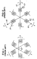
- Figure 1 illustrates schematically three stator coils 3, 6, and 9, which are contained in a three-phase synchronous motor (not shown).
- Figure 2 shows the coils, but with connecting wires W of Figure 1 omitted, to avoid clutter.
- currents 13, 16, and 19 are generated in the respective coils. Each current produces a magnetic field B3, B6, and B9, as indicated.
- the coils 3, 6, and 9 are physically positioned to be 120 degrees apart, as shown, so that the fields B3, B6, and B9 are also positioned 120 degrees apart physically (as opposed to chronologically). This arrangement allows creation of a magnetic field which rotates in space at a constant speed, if proper currents are generated in the coils, as will now be explained.
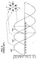
- Figure 3 illustrates three-phase currents.
- the vertical axis on the coordinates runs from negative unity to positive unity for simplicity. In practice, one would multiply the values of unity by the actual peak-to-peak values of the currents being used.
- SIN3, SIN6, and SIN9 are created respectively in coils 3, 6, and 9, as indicated.
- the sine waves are separated by 120 chronological, or electrical, degrees.
- Coil 3 resides at zero physical degrees.
- SIN3 begins at zero electrical degrees, as indicated on the plot.
- coil 6 stands at 120 degrees from coil 3.
- SIN6 begins at 120 degrees, as indicated on the plot.
- coil 9 stands at 240 degrees from coil 3.
- SIN9 begins at 240 degrees, as indicated on the plot.
- Each coil 3, 6, and 9 produces a magnetic field, as indicated. Those three magnetic fields add vectorially to produce a single magnetic field, which rotates at a constant angular velocity, if the sine waves SIN3, SIN6, and SIN9 have the same peak-to-peak magnitudes, and are exactly 120 degrees apart in phase.
- Figure 4 represents the vector sum B of magnetic fields B3, B6, and B9 of Figure 2.
- Vector B in Figure 4 rotates in the direction of arrow 30.
- FIG. 5 shows the coils of Figures 1 - 3 superimposed over the rotating vector B.
- Rotor ROT contains an apparatus which generates a rotor magnetic field BR.
- the apparatus may take the form of a permanent magnet PM.
- the Inventors have identified problems which can occur if the coils 3, 6, and 9 become short-circuited, and have developed stratagems for preventing these short-circuits.
- An object of the invention is to provide an improved stator system for an electric motor.
- a further object of the invention is to provide a stator topology which reduces likelihood of phase-to-phase shorts in an electric motor.
- a stator for an electric motor contains stator teeth, with slots between adjacent teeth. Some, or all, of the teeth have phase coils wrapped around them, but no slot contains coils for more than one phase. Thus, no short can occur within a slot which shorts one phase to another.
- Figure 1 illustrates coils in a three-phase motor of the prior art.
- Figure 2 illustrates magnetic field vectors generated by the three coils.
- Figure 3 illustrates three-phase currents applied to the coils of Figures 1 and 2.
- Figure 4 illustrates the rotating vector sum B of the three magnetic fields of Figure 2.
- Figure 5 illustrates the coils of Figures 1 - 3 and the rotor of a motor superimposed over Figure 5.
- Figure 6 illustrates a possible short circuit SC between two coils C1 and C2.
- Figure 7 illustrates a relay 40 which is sometimes opened when the short-circuit of Figure 6 occurs.
- Figure 8 illustrates transistor switches commonly used to power the motor coils, and a short circuit between two coils.
- Figure 9 illustrates a stator structure found in the prior art.
- Figure 10 is a perspective schematic rendition of Figure 9.
- FIG. 11 illustrates one form of the invention.
- Figure 12 is a perspective schematic rendition of Figure 11.
- Figure 13 illustrates a stator structure found in the prior art.
- Figure 14 is a perspective schematic rendition of Figure 13.
- FIG. 15 illustrates one form of the invention.
- Figure 16 is a perspective schematic rendition of Figure 15.
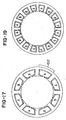
- FIG. 17 illustrates one form of the invention.
- Figure 18 is a perspective schematic rendition of Figure 17.
- FIG 19 illustrates one form of the invention.
- Figure 20 illustrates, in schematic form, the so-called "loose tooth” mode of construction of a stator.
- FIGS 21, 22, 23, and 24 illustrate forms of the invention which form coils on stator teeth, when removed from the assembled stator.
- Figure 25 illustrates a vehicle which utilizes motors containing stators described herein.
- Figure 6 illustrates a short circuit SC between two coils in a motor.
- the rotor field BR in swinging past coils C1 and C2, generates voltages in those coils. Those voltages generate a current I.
- the motor is acting as a generator, in this respect.
- the current produces a torque that opposes the motion of the rotor.
- the drag-torque is repeated, and the repetition is perceived as vibration.
- the drag reduces the power output of the motor. That is, the current I, in passing through the resistance contained in the coils C1 and C2, produces Joule heating.
- the energy required for the Joule heating must be supplied by the power delivered to the motor.
- the rotor in general, will not produce the same amount of power as previously, because part of the applied energy is now used for the Joule heating.
- the drag on the rotor occurs when the rotor field BR sweeps past coils C1 and C2, the drag is not constant, but periodic. This periodic drag will be sensed as vibration by the driver.
- the motor in question can be equipped with a relay 50, as in Figure 7, which connects all phases to the electrical neutral point NP. This relay is opened when such a short occurs, thereby shutting down the motor and eliminating the drag torque by eliminating the short circuit current.
- Figure 8 illustrates six transistors T1 - T6 which can be used to control currents to the coils C1 - C3 of the motor. The transistors are used to synthesize the sine waves of Figure 3, as known in the art.
- a battery 51 supplies power.
- Relay 50 may be present, as in Figure 7
- diodes such as D1 are inherent in the characteristics of each transistor. The short SC may cause unwanted current to pass through the diodes in some circumstances.
- Figure 9 illustrates a prior-art three-phase stator
- Figure 10 is a perspective schematic showing one possible arrangement of the three-dimensional shapes of the coils. It is emphasized that Figure 10 is a schematic, showing primarily positioning of the coils. It does not show the fact that the coils, in general, will be of a sufficiently large cross section to fully occupy the stator slots.
- a 9-slot stator is shown, which can be used with an 8-pole or 10-pole rotor.
- Stator tooth 54 is identified for reference in both Figures.
- Each square ring in Figure 10 represents a coil, such as coil A.
- the stator is of the 9-slot type, as in Figures 9 and 10. However, in Figures 11 and 12, only three coils are present, which fill only six of the slots. The slots labeled E are empty.
- FIGS 13 and 14 illustrate a twelve-slot stator, which can be used with an eight-pole or ten-pole rotor.
- Stator tooth 70 is marked for reference.
- Coils A and B, which share slot 72, can make contact at point 73, and become shorted.
- Figures 15 and 16 show an embodiment which eliminates this problem.
- a twelve-slot stator is used, as in Figures 13 and 14. However, no coils share a common stator slot. For example, slots 83 and 86 are occupied by a single coil, coil A, which is one half of the phase comprising that coil A and the coil A 180 degrees opposite.
- the two coils for purposes of failure analysis, are considered independent entities. It is considered unlikely that insulation, on two independent entities will fail at the same time, and same place. This situation is to be distinguished from that of Figures 13 and 14, for example. In those Figures, insulation of two coils can make contact at point 73. Thus, vibration can abrade away insulation at a common point. The two coils are not treated as independent entities, for statistical purposes. Additionally, insulation is placed between the stator tooth 89 and the coils for phases A and C, adding additional redundancy.
- Figures 17 and 18 illustrate an eight-slot stator, which can be used with a six-pole rotor. Again, no slot, such as slot 100, contains more than one coil, or more than one phase.
- Figure 19 illustrates a sixteen-slot stator, which can be used with a twelve-pole rotor.
- Figure 20 is a schematic conceptualization of a so called "loose tooth” winding which is used to simplify stator construction.
- Image 110 illustrates a stator.
- the stator is constructed of laminations, in order to reduce eddy-current losses.
- Loose tooth assembly is a technique which is useful for the construction of multiple phase per slot windings such as those shown in Figures 9 and 13 for example, as long as each coil is wound around a single tooth. It is also useful for single phase per slot windings such as Figures 11, 15, 17, and 19.
- stator is broken into sectors, as indicated in image 115.
- Wedge 117 represents one sector.
- wire 123 is wrapped around each tooth T.
- the sectors are then re-assembled into the form indicated in image 110.
- the assembly includes a peripheral, or circumferential, rim 118, bearing a radial array of teeth 119. Each tooth bears a pole face 116.
- stator yoke 118 In general, magnetic flux from the coil wound on each tooth and magnetic flux from the permanent magnets on rotor 124 passing through each tooth must pass through the stator yoke 118 as it completes its circuit illustrated by parallel magnetic flux paths 125. When the stator is split into sections 117, the magnetic flux path must pass through a single break in the yoke 118 in each of the paths 125.
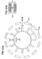
- FIG. 21 illustrates another approach. Stator 130 is broken into the pieces indicated. For each tooth 132, a coil C is wound at a different location, as on a mandrel (not shown) having a cross sectional size and shape slightly larger than that of tooth 132. The mandrel forms a hollow core CO in the coil. Then the coil C is slid onto tooth 132, and the process is repeated for each tooth. Then the pieces of the stator 130 are re-assembled into an intact stator with insulation placed between the coil C and the tooth 32.
- the assembly process of Figure 21 results in a degradation of the magnetic field paths.
- the magnetic field path 135 (shown with its connections once the exploded view of Figure 21 is assembled) must pass through two breaks in the yoke of the stator.
- the magnetic field path must form a continuous loop, which closes on itself.
- Each break represents a reluctance to the magnetic path which can diminish performance and affect cogging torque, the torque ripple which occurs due to permanent magnets and the reluctance of the permanent magnet path.
- the method of Figure 21 while superior to that of Figure 20 for winding convenience, is inferior for the magnetic performance.
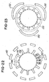
- Figures 22 and 23 conceptually illustrate two different approaches to splitting the stator into pieces while allowing a coil to be assembled onto each tooth.
- the segments 136 by themselves, form the rim of the stator, as indicated by phantom segments 137.
- the segments 140 together with the radially outer ends 143 of the teeth 144, form the rim of the stator. Segments 140 fit between the ends 143, as indicated by phantom segments 148.
- Figure 23 can be viewed as showing a variation of Figure 21. In the latter, one segment 136 is generated for each tooth. In Figure 23, three segments 150 are generated, which together form the rim 153 of the stator. These preceding loose-tooth approaches are applicable to the prior art situation of, for example, Figures 13 and 14. That is, coils A and B in Figure 22 would share slot 160.
- stator is constructed of two types of parts.
- One type includes rim sections 170 which contain a tooth 173.
- the other type is a tooth section 176, having a free end 179, over which a coil can slide.
- Coils C are wound, separate from the tooth sections 176.
- the coils C are then inserted over the teeth 176, from the radially outer direction, over ends 179, as indicated by arrow A.
- Pole faces 201 retain the coils C: the hollow cores are not large enough to fit over the pole faces 201.
- the tooth sections 176, now bearing coils C are assembled with rim sections 170, to form the stator 200.
- Such construction can not be used with conventional windings in which multiple phases share slots as shown in Figures 9 and 13 for example since a coil must be placed on each stator tooth.
- Figure 24 offers improvement in the magnetic circuit paths.
- the parallel magnetic flux paths from rotor 174 for a single coil are shown by 175 in Figure 24.
- the paths must only traverse a single break in the stator iron as opposed to the two breaks of the techniques in Figures 21, 22, and 23.
- the technique of Figure 24 combined with the single phase per slot winding exemplified in Figures 11, 15, 17, and 19 allows the simplified coil assembly benefits of Figures 21, 22, and 23 with the improved magnetic circuit of Figure 20.
- FIG. 25 illustrates one form of the invention.
- a motor vehicle 203 contains one or more electric motors 207, such as motors which operate power steering, power brakes, windshield wipers, and so on.
- One or more of the motors utilize the winding arrangements described herein.
- the motors can be assembled using procedures described herein, and then installed into the vehicle.
- a stator tooth can be defined as a body lying on a radius of a motor, which acts as a magnetic core for a coil of wire which is wound around the body.
- a radial array of such bodies is often provided.
- the bodies, or teeth, are generally separate at their radially inner ends, such as ends EE in Figure 12.
- the bodies are often connected to a common ring at their radially outer ends, as in Figure 12. Other definitions are possible.
Landscapes
- Engineering & Computer Science (AREA)
- Power Engineering (AREA)
- Iron Core Of Rotating Electric Machines (AREA)
- Windings For Motors And Generators (AREA)
Abstract
Description
Claims (37)
- A stator for an electric motor, comprising:a) a radial array of 2N teeth, definable as 1, 2, 3, to 2N;b) N coils, one wound around each even tooth; andc) no coil wound around any odd tooth.
- A stator for an electric motor, comprising:a) a first group of stator teeth, eachi) acting as magnetic core for a single coil wound around it; andii) carrying substantially all magnetic flux of the coil wound around it;b) a second group of stator teeth, having no coils wound around them.
- Stator according to claim 2, wherein slots are present between adjacent teeth, and some slots contain no coils.
- A stator for an electric motor, comprising:a) a radial array of stator teeth, separated by stator slots; andb) phase coils encircling at least some stator teeth, wherein no slot contains coils from more than one phase.
- Stator according to claim 4, wherein the radial array of stator teeth comprises at least two teeth.
- Apparatus, comprising:a) a stator for an electric motor, comprising coil slots; andb) in any slot, no coils from more than a single phase.
- Apparatus, comprising:wherein all currents in any slot are in-phase.a) a stator for an electric motor, comprising coil slots;b) a rotor;c) coils in respective slots,
- Apparatus according to daim 7, wherein no currents in any slot have different phases.
- Apparatus according to claim 1, and further comprising a motor vehicle which powers the motor.
- Apparatus according to claim 5, and further comprising a motor vehicle which powers the motor.
- Apparatus according to claim 7, and further comprising a motor vehicle which powers the motor.
- A stator for an electric motor, comprising:a) an outer rim;b) stator teeth extending radially inward from the rim;c) breaks in the stator, which allowi) individual stator teeth to be removed from the stator; andii) a pre-formed coil to be mounted onto selected stator teeth.
- A stator for an electric motor, comprising:a) a radial array of stator teeth, with a stator slot present between adjacent pairs of teeth;b) a rim surrounding the teeth; andc) breaks in the rim, teeth, or both, which allowi) individual teeth to be separated from the stator andii) a pre-formed coil to be inserted onto selected individual teeth.
- Stator according to claim 13, wherein structural configuration of the removed stator teeth does not require deformation of the pre-formed coil during mounting.
- Stator according to claim 13, wherein structural configuration of the removed stator teeth does not require deformation of the pre-formed coil during insertion.
- A collection of parts for constructing a stator for an electric motor, comprising:a) a plurality of pre-formed coils;b) a first set of stator teeth having radially outer ends which fit into the pre-formed coils; andc) a second set of stator teeth, each having a segment of a rim mounted thereon.
- Collection according to claim 16, wherein a radial array of stator teeth connected to an outer rim is generated wheni) the first set of stator teeth is positioned in odd-numbered sectors of a circle, andii) the second set of stator teeth is positioned in even-numbered sectors of the circle.
- Collection according to claim 17, wherein the segments of the rim collectively form a circular periphery of the stator.
- Collection according to claim 17, wherein the segments of the rim, together with radially outer sections of stator teeth in the first set, collectively form a circular periphery of the stator.
- A stator for an electric motor, comprising:a) a radial array of stator teeth, extending inwardly from a circumferential rim;b) breaks in the rim, teeth, or both, which allowi) individual teeth to be separated from the stator andii) a pre-formed coil to be inserted onto selected individual teeth.
- Stator according to claim 20, wherein parts of the rim are connected to some teeth when removed, preventing insertion of pre-formed coils onto such teeth.
- A stator for an electric motor, comprising:a) an outer rim;b) stator teeth extending radially inward from the rim;c) breaks in the rim, which define the stator teeth into two groups wherein:i) in one group, each tooth has a radially outward end over which a stator coil can be inserted;ii) in the second group, each tooth has a radially outward end connected to a segment of the circular rim.
- Stator according to claim 22, and further comprisingd) coils around teeth in the first group; ande) no coils around any teeth in the second group.
- Stator according to claim 22, wherein every tooth bears a pole face on its radially inward end.
- A method of constructing a stator for an electric motor, comprising:a) forming coils, each having a hollow core;b) placing a stator tooth in the hollow core of each coil;c) connecting ends of the stator teeth with arcuate segments to thereby form a circular rim having coil-bearing stator teeth extending radially inward therefrom.
- Method according to claim 25, wherein each stator tooth has a pole face on one end.
- Method according to claim 25, wherein the pole face blocks removal of a coil past the pole face.
- A method of constructing a stator for an electric motor, comprising:a) forming N coils, each having a hollow core;b) providing a radial array of 2N stator teeth such thati) teeth in odd-numbered positions are surrounded by coils; andii) teeth in even-numbered positions are surrounded by no coils.
- A method of constructing a stator for an electric motor, comprising:a) forming a group of generally T-shaped structures, each comprising a stem and a bar, withi) the bar being arcuate, andii) the stem located on the concave side of the arcuate bar;b) forming a group of N stator teeth, each having a radially outward end;c) forming N coils, each having a hollow core;d) placing one stator tooth into the hollow core of each stator tooth;e) placing no coils on any stems;f) assembling the T-shaped structures, the N coils, and the N stator teeth into a stator.
- Method according to claim 29, and further comprising placing the stator into a motor vehicle.
- Apparatus according to claim 1, wherein the coils provide multiple phases.
- Method of constructing a stator for an electric motor, comprising:a) inserting pre-wound coils, each having a core, onto stator teeth carried by stator sections;b) assembling the stator sections into a stator, whereini) junctions between stator sections are present, andii) a continuous loop exists around at least one coil, which loop (1) passes through said core and (2) crosses no more than a single junction.
- Method according to daim 32, wherein a continuous loop exists around every coil, which loop (1) passes through said core and (2) crosses no more than a single junction.
- Method of constructing a stator for an electric motor, comprising:c) inserting pre-wound coils, each having a core, onto stator teeth carried by stator sections;d) assembling the stator sections into a stator, whereini) junctions are present between stator sections, andii) a path exists for flux lines generated by a coil to follow, which path crosses only one junction.
- Method according to claim 34, wherein a path exists for every coil, which flux lines can follow, and which crosses only a single junction.
- Apparatus, comprising:wherein (1) junctions exist in the stator, between adjacent parts, and (2) for at least one coil, a path exists which crosses no more than one junction, which flux lines generated by the coil can follow.e) a collection of coils;f) a group of parts which, together with some of the coils, can be assembled into stators for electric motors, which have coils mounted on stator teeth,
- Apparatus according to claim 36, wherein a path crossing no more than a single junction is available for magnetic flux lines generated by every coil.
Applications Claiming Priority (2)
| Application Number | Priority Date | Filing Date | Title |
|---|---|---|---|
| US773967 | 2004-02-06 | ||
| US10/773,967 US20050174006A1 (en) | 2004-02-06 | 2004-02-06 | Winding topologies for stators in brushless motors |
Publications (2)
| Publication Number | Publication Date |
|---|---|
| EP1562276A2 true EP1562276A2 (en) | 2005-08-10 |
| EP1562276A3 EP1562276A3 (en) | 2006-10-04 |
Family
ID=34679398
Family Applications (1)
| Application Number | Title | Priority Date | Filing Date |
|---|---|---|---|
| EP05002490A Withdrawn EP1562276A3 (en) | 2004-02-06 | 2005-02-07 | Winding topologies for stators in brushless motors |
Country Status (2)
| Country | Link |
|---|---|
| US (1) | US20050174006A1 (en) |
| EP (1) | EP1562276A3 (en) |
Cited By (1)
| Publication number | Priority date | Publication date | Assignee | Title |
|---|---|---|---|---|
| WO2008034792A1 (en) * | 2006-09-18 | 2008-03-27 | Robert Bosch Gmbh | Synchronous machine |
Families Citing this family (10)
| Publication number | Priority date | Publication date | Assignee | Title |
|---|---|---|---|---|
| US7495363B2 (en) * | 2005-12-21 | 2009-02-24 | Raytheon Company | Maximum conductor motor and method of making same |
| JP4251196B2 (en) * | 2006-06-16 | 2009-04-08 | トヨタ自動車株式会社 | Motor for steering device |
| US8944783B2 (en) * | 2006-06-27 | 2015-02-03 | Schlumberger Technology Corporation | Electric progressive cavity pump |
| US20100133945A1 (en) * | 2009-06-05 | 2010-06-03 | Remy International Inc. | Segmented stator core winding apparatus and method of winding a segmented stator core |
| US8614530B2 (en) * | 2009-12-17 | 2013-12-24 | Remy Technologies, L.L.C. | Stator core for an electric machine |
| JP6452889B2 (en) * | 2016-03-29 | 2019-01-16 | 三菱電機株式会社 | Electric motor |
| CN107070016A (en) * | 2017-04-18 | 2017-08-18 | 苏州汇川联合动力系统有限公司 | Double remaining stators and double remaining motors |
| GB2586989B (en) * | 2019-09-11 | 2022-07-27 | Rolls Royce Plc | Electric Machines |
| CN114846722B (en) * | 2019-12-26 | 2025-06-24 | 阿莫泰克有限公司 | Stator for electric motor and electric motor including the same |
| JP7365956B2 (en) * | 2020-04-08 | 2023-10-20 | 株式会社ミツバ | Brushless motor and brushless motor control method |
Family Cites Families (31)
| Publication number | Priority date | Publication date | Assignee | Title |
|---|---|---|---|---|
| US2517105A (en) * | 1947-03-14 | 1950-08-01 | Gen Electric | Field coil for dynamoelectric machines |
| US2903610A (en) * | 1956-08-22 | 1959-09-08 | Labinal Sa Ets | Dynamo-electric machine field magnet construction with split poles |
| US3514650A (en) * | 1968-10-02 | 1970-05-26 | Us Army | Variable reluctance synchronal dynamo |
| US4100473A (en) * | 1974-05-01 | 1978-07-11 | National Research Development Corporation | Electric stepper motors |
| US5418416A (en) * | 1983-09-05 | 1995-05-23 | Papst Licensing Gmbh | Brushless three-phase DC motor |
| US4609862A (en) * | 1985-09-09 | 1986-09-02 | General Motors Corporation | Twin winding three-phase alternator with zero slot coupling |
| US4812695A (en) * | 1986-08-15 | 1989-03-14 | Marathon Electric Manufacturing Corporation | Annular stator core construction |
| US5157298A (en) * | 1987-09-11 | 1992-10-20 | Toyota Jidosha Kabushiki Kaisha | Brushless motor with greater efficiency |
| US5107159A (en) * | 1989-09-01 | 1992-04-21 | Applied Motion Products, Inc. | Brushless DC motor assembly with asymmetrical poles |
| JP2888142B2 (en) * | 1993-11-08 | 1999-05-10 | 三菱電機株式会社 | Rotary motor and method of manufacturing the same |
| US5095237A (en) * | 1990-03-20 | 1992-03-10 | Nova Corporation Of Alberta | Sectoral core for magnetic bearing |
| JP2758535B2 (en) * | 1992-07-16 | 1998-05-28 | 株式会社日立製作所 | Electronic throttle control |
| US5541463A (en) * | 1993-06-15 | 1996-07-30 | Eko Technologies, Inc. | Flex path and core loss reduction assembly |
| US5492509A (en) * | 1994-06-06 | 1996-02-20 | Ford Motor Company | Operating range selection of an automatic transmission |
| US5723930A (en) * | 1995-01-05 | 1998-03-03 | Industrial Technology Research Institute | Stators incorporating blank winding slots for a permanent magnet brushless motor and method of winding thereof |
| US5729071A (en) * | 1995-01-31 | 1998-03-17 | Steiner; Robert E. | Low cost multi-pole motor constructions and methods of manufacture |
| US5874796A (en) * | 1995-02-10 | 1999-02-23 | Petersen; Christian C. | Permanent magnet D.C. motor having a radially-disposed working flux gap |
| DE19549180A1 (en) * | 1995-12-30 | 1997-07-03 | Bosch Gmbh Robert | Stator for electrical machine |
| DE69735741T2 (en) * | 1996-02-23 | 2006-09-14 | Matsushita Electric Industrial Co., Ltd., Kadoma | ENGINE |
| DE19612016A1 (en) * | 1996-03-15 | 1997-09-18 | Daimler Benz Ag | Process for computer-aided geometry modeling |
| JPH1042531A (en) * | 1996-05-24 | 1998-02-13 | Matsushita Electric Ind Co Ltd | Electric motor |
| JP3490219B2 (en) * | 1996-06-26 | 2004-01-26 | ミネベア株式会社 | Rotating electric machine |
| JP2001190050A (en) * | 1999-04-01 | 2001-07-10 | Asmo Co Ltd | Rotating-field type motor |
| US6133663A (en) * | 1999-04-01 | 2000-10-17 | A. O. Smith Corporation | Brushless permanent magnet machine |
| US6236133B1 (en) * | 2000-03-24 | 2001-05-22 | Denso Corporation | Three-phase brushless motor |
| JP2001275283A (en) * | 2000-03-28 | 2001-10-05 | Mitsubishi Electric Corp | Stator of vehicle alternator |
| US20020163275A1 (en) * | 2001-05-04 | 2002-11-07 | Chun-Pu Hsu | Device with a stator having high performance flat coils |
| US6759780B2 (en) * | 2001-05-08 | 2004-07-06 | Delphi Technologies, Inc. | Fractional-slot winding motor |
| DE10124415A1 (en) * | 2001-05-18 | 2002-11-28 | Siemens Ag | Electrical machine |
| JP3816353B2 (en) * | 2001-05-25 | 2006-08-30 | 三菱電機株式会社 | Electric power steering motor |
| DE10236941A1 (en) * | 2002-08-12 | 2004-03-04 | Siemens Ag | Stator plate packet for synchronous machine, has fixed tooth head on inner end of every second pole tooth in peripheral direction, and tooth with removable tooth head between each 2 teeth with fixed heads |
-
2004
- 2004-02-06 US US10/773,967 patent/US20050174006A1/en not_active Abandoned
-
2005
- 2005-02-07 EP EP05002490A patent/EP1562276A3/en not_active Withdrawn
Cited By (1)
| Publication number | Priority date | Publication date | Assignee | Title |
|---|---|---|---|---|
| WO2008034792A1 (en) * | 2006-09-18 | 2008-03-27 | Robert Bosch Gmbh | Synchronous machine |
Also Published As
| Publication number | Publication date |
|---|---|
| US20050174006A1 (en) | 2005-08-11 |
| EP1562276A3 (en) | 2006-10-04 |
Similar Documents
| Publication | Publication Date | Title |
|---|---|---|
| JP5040303B2 (en) | Rotating electric machine | |
| US7250702B2 (en) | Rotary electric machine comprising a stator and two rotors | |
| KR101730525B1 (en) | Brush-less synchronous motor | |
| US10862355B2 (en) | Armature with a core having teeth of different circumferential widths and electric motor including the armature and a rotor | |
| CN108352750B (en) | Rotating electrical machine and rotating electrical machine system | |
| JP6068953B2 (en) | Electric motor | |
| KR101998508B1 (en) | Rotary electric machine | |
| JP2009077468A (en) | Rotating electric machine and method of manufacturing rotating electric machine | |
| EP3217516B1 (en) | Rotating electrical machine | |
| US20100117465A1 (en) | Rotating electric machine | |
| JP2010183781A (en) | Motor generator | |
| EP3070817B1 (en) | Stator and rotating electric machine equipped with same | |
| US20220263356A1 (en) | Motor | |
| US20050174006A1 (en) | Winding topologies for stators in brushless motors | |
| WO2017110760A1 (en) | Rotating electrical machine and method of manufacturing same | |
| JP2016025743A (en) | Rotating electric machine stator | |
| US20230318382A1 (en) | Stator and motor | |
| US7528517B2 (en) | Distribution of motor heat sources | |
| JP2006288028A (en) | Multi-winding motor | |
| JP2017028972A (en) | AC excitation synchronous rotating electric machine | |
| JP6582973B2 (en) | Rotating electric machine and manufacturing method thereof | |
| JP5446140B2 (en) | Rotating electrical machine rotor | |
| JPH10126991A (en) | Centralized rotating electric machine and electric vehicle using the same | |
| JP2005117731A (en) | Permanent magnet type 2-phase rotary electric machine | |
| JP2018007413A (en) | Electric motor stator and manufacturing method therefor |
Legal Events
| Date | Code | Title | Description |
|---|---|---|---|
| PUAI | Public reference made under article 153(3) epc to a published international application that has entered the european phase |
Free format text: ORIGINAL CODE: 0009012 |
|
| 17P | Request for examination filed |
Effective date: 20050207 |
|
| AK | Designated contracting states |
Kind code of ref document: A2 Designated state(s): AT BE BG CH CY CZ DE DK EE ES FI FR GB GR HU IE IS IT LI LT LU MC NL PL PT RO SE SI SK TR |
|
| AX | Request for extension of the european patent |
Extension state: AL BA HR LV MK YU |
|
| PUAL | Search report despatched |
Free format text: ORIGINAL CODE: 0009013 |
|
| AK | Designated contracting states |
Kind code of ref document: A3 Designated state(s): AT BE BG CH CY CZ DE DK EE ES FI FR GB GR HU IE IS IT LI LT LU MC NL PL PT RO SE SI SK TR |
|
| AX | Request for extension of the european patent |
Extension state: AL BA HR LV MK YU |
|
| AKX | Designation fees paid |
Designated state(s): AT BE BG CH CY CZ DE DK EE ES FI FR GB GR HU IE IS IT LI LT LU MC NL PL PT RO SE SI SK TR |
|
| 17Q | First examination report despatched |
Effective date: 20070903 |
|
| STAA | Information on the status of an ep patent application or granted ep patent |
Free format text: STATUS: THE APPLICATION IS DEEMED TO BE WITHDRAWN |
|
| 18D | Application deemed to be withdrawn |
Effective date: 20080115 |