EP1562239A1 - Polymer actuator comprising electrodes made of carbon nano-fibres - Google Patents
Polymer actuator comprising electrodes made of carbon nano-fibres Download PDFInfo
- Publication number
- EP1562239A1 EP1562239A1 EP20040252033 EP04252033A EP1562239A1 EP 1562239 A1 EP1562239 A1 EP 1562239A1 EP 20040252033 EP20040252033 EP 20040252033 EP 04252033 A EP04252033 A EP 04252033A EP 1562239 A1 EP1562239 A1 EP 1562239A1
- Authority
- EP
- European Patent Office
- Prior art keywords
- actuator
- electrodes
- sheet member
- carbon nano
- nano fibers
- Prior art date
- Legal status (The legal status is an assumption and is not a legal conclusion. Google has not performed a legal analysis and makes no representation as to the accuracy of the status listed.)
- Granted
Links
Images


Classifications
-
- H—ELECTRICITY
- H10—SEMICONDUCTOR DEVICES; ELECTRIC SOLID-STATE DEVICES NOT OTHERWISE PROVIDED FOR
- H10N—ELECTRIC SOLID-STATE DEVICES NOT OTHERWISE PROVIDED FOR
- H10N30/00—Piezoelectric or electrostrictive devices
- H10N30/20—Piezoelectric or electrostrictive devices with electrical input and mechanical output, e.g. functioning as actuators or vibrators
- H10N30/204—Piezoelectric or electrostrictive devices with electrical input and mechanical output, e.g. functioning as actuators or vibrators using bending displacement, e.g. unimorph, bimorph or multimorph cantilever or membrane benders
- H10N30/2041—Beam type
- H10N30/2042—Cantilevers, i.e. having one fixed end
-
- B—PERFORMING OPERATIONS; TRANSPORTING
- B82—NANOTECHNOLOGY
- B82Y—SPECIFIC USES OR APPLICATIONS OF NANOSTRUCTURES; MEASUREMENT OR ANALYSIS OF NANOSTRUCTURES; MANUFACTURE OR TREATMENT OF NANOSTRUCTURES
- B82Y10/00—Nanotechnology for information processing, storage or transmission, e.g. quantum computing or single electron logic
-
- H—ELECTRICITY
- H10—SEMICONDUCTOR DEVICES; ELECTRIC SOLID-STATE DEVICES NOT OTHERWISE PROVIDED FOR
- H10N—ELECTRIC SOLID-STATE DEVICES NOT OTHERWISE PROVIDED FOR
- H10N30/00—Piezoelectric or electrostrictive devices
- H10N30/01—Manufacture or treatment
- H10N30/06—Forming electrodes or interconnections, e.g. leads or terminals
-
- H—ELECTRICITY
- H10—SEMICONDUCTOR DEVICES; ELECTRIC SOLID-STATE DEVICES NOT OTHERWISE PROVIDED FOR
- H10N—ELECTRIC SOLID-STATE DEVICES NOT OTHERWISE PROVIDED FOR
- H10N30/00—Piezoelectric or electrostrictive devices
- H10N30/80—Constructional details
- H10N30/87—Electrodes or interconnections, e.g. leads or terminals
- H10N30/877—Conductive materials
- H10N30/878—Conductive materials the principal material being non-metallic, e.g. oxide or carbon based
Definitions
- the present invention relates to an actuator and a material for electrodes of the actuator
- the actuator is capable of greatly deforming a sheet member made of a polymer material on application of an electric field.
- An actuator having a flexible sheet member made of a polymer material and a pair of electrodes provided on the faces of said sheet member is known.
- the sheet member is deformed by applying an electric field.
- a conventional actuator is disclosed in Japanese Patent Gazette No. 2000-49397.
- the actuator is shown in Fig. 17.
- the actuator 10 has a one-layer polyurethane film 12 and a pair of electrodes 11 provided on the faces of the polyurethane film 12. Deformation (bending electrostriction) is caused by applying an electric field to the actuator 10.
- the electrodes 11 are formed on the both faces of the polyurethane film 12 by evaporating gold.
- the actuator 10 bends as shown in Fig. 18. Therefore, the actuator 10 can be used to actuate other members. By employing the bending action, various kinds of actuators can be realized.
- the inventors of the present invention studied and found that the deformation of the actuator was limited by a structure of the electrodes 11.
- the electrodes 11 are formed by evaporating gold, so the fine particles of gold are stuck on the polyurethane film 12 by evaporation and keep contact each other.
- the actuator 10 having such electrodes 11 is deformed, the electrodes 11 are cracked so that electric conduction is stopped. Therefore, the actuator 10 cannot be greatly deformed itself. If the electrodes 11 are made thick so as not to be cracked, the polyurethane film 12 cannot bend.
- a preferred embodiment of the present invention may provide an actuator capable of greatly bending a flexible sheet member.
- the present invention provides a material for electrodes of the actuator of the present invention, use of such material, and methods of making and using actuators.
- the actuator of the present invention comprises:
- one end of the carbon nano fibers constituting the electrodes may bite into the sheet member.
- the polymer material may be, for example, polyurethane resin or silicone resin.
- the material for electrodes of the actuator is made of carbon nano fibers.
- the electrodes are made of carbon nano fibers, which can be merely in contact each other, so that the electrodes can be flexible and can fully follow deformation of the sheet member with maintaining mutual contact. Therefore, the actuator can maximally deform the sheet member.
- FIG. 1 An actuator of the present embodiment is shown in Fig. 1.
- the actuator 20 has a sheet member 22 made of a flexible polymer material.
- a pair of electrodes 24, which are mainly made of carbon nano fibers, are respectively provided on the both side faces of the sheet member 22.
- the electrodes 24 may be formed to cover the whole side faces of the sheet member 22 or formed into prescribed patterns.
- the electrodes 24 are formed to cover the whole side faces of the sheet member 22 with uniform thickness. By applying an electric field to one end to another electrode 24, the sheet member 22 is greatly bended. If the electrodes 24 are patterned, the sheet member 22 can be optionally deformed.
- the polymer material of the sheet member 22 is not limited.
- polyurethane especially polyurethane whose soft segment includes polyester may be employed (see Japanese Patent Gazette 2000-49397).
- silicone gel polyvinyl chloride, polyethylene, polypropylene, PET, etc. may be employed as the polymer material.
- a material whose molecules are oriented by a DC electric field, e.g., polyurethane elastomer including polycarbonate polyol, is employed as the polymer material (see Japanese Patent Gazette No. 7-240544).
- the improved electrodes 24 can greatly deform, and polymer materials, whose crystals have no orientation, can be employed.
- a plasticizer may be added to the polymer so as to make a flexible polymer material.
- a little electrolyte e.g., salt
- an electric current of nA level can pass through the polymer material when the electric field is applied.
- the polymer material may have electroconductivity, which is as small as that of a semiconductor. Even in a polymer material having perfect insulativity, e.g., silicone gel, by doping the electrolyte, the material can be relatively greatly deformed when the electric field is applied.
- a material of the electrodes 24 is carbon nano fibers.
- carbon nano tubes which are formed by a vapor growth process, may be employed as the carbon nano fibers.
- the carbon nano fibers formed by the vapor growth process are very fine fibers having diameter of dozens nm to one hundred and dozens nm and length of less than 20 um.
- the material of the electrodes 24 is constituted by carbon nano fibers only.
- carbon components e.g., graphite, carbon, may be added to the carbon nano fibers.
- the electrodes 24, which is formed by the material mainly made of carbon nano fibers, are respectively provided on the both side faces of the sheet member 22, which is made of the flexible polymer material.
- Carbon nano fibers are dispersed in a solvent, e.g., ethanol, to form into paste.
- the paste is applied on the both side faces of the sheet member 22 and dried.
- the dried carbon nano fiber layers become the electrodes 24.
- surfaces of the electrodes 24 are pressed by pressing means, e.g., a roller, so as to completely adhere the electrodes 24 on the side faces of the sheet member 22.
- pressing means e.g., a roller
- the carbon nano fibers may be coated with layers of electroconductive resin so as to prevent the carbon nano fibers from falling off.
- the carbon nano fibers are very fine fibers, and the electrodes 24 are made of many carbon nano fibers. Unlike the conventional electrode made of fine particles of gold, even if the sheet member 22 is greatly deformed, the flexible carbon nano fibers constituting the electrodes 24 can follow the deformation of the sheet member 22 without separating each other. Namely, the mutual contact of the carbon nano fibers can be maintained while the electrodes 24 follow the deformation of the sheet member 22.
- the sheet member 22 can be greatly deform. Note that, the sheet member 22 is originally greatly deformable.
- the electrodes 24 are made of the flexible carbon nano fibers, which are capable of following the deformation of the sheet member 22 with maintaining their mutual contact, the sheet member 24 can be maximally deformed.
- one end of the carbon nano fibers can bite into the side faces of the sheet member 22 by pressing the electrodes 24 with, for example, the roller.
- Carbon fibers formed by the vapor growth process have been used as fibers for a field electron emitter. Electrons are emitted from sharp ends of the carbon fibers when a high electric field is applied.
- the inventors found that electrons concentratedly emitted from the ends of the carbon nano fibers toward an inner solid or gel part of the sheet member 22 when the electric field is applied to the electrodes 24. With this action, the sheet member 22 can be effectively deformed or bended.
- the ends of the carbon nano fibers bite into the sheet member 22, and electrons are emitted from the ends toward the inner part of the sheet member 22. With this action, electric charges can be effectively charged, so that the asymmetrical existence of electric charges can be promoted. Therefore, the sheet member 22 can be deformed with high responsibility.
- the electrodes 24 may be made of powderlike material (aggregrated) too.
- the electrodes 24 are formed by uniformly scattering the powders onto the side faces of the sheet member 22 and pressing the powders with, for example, a roller.
- silicone gel has viscous surfaces, the powders can be adhered on the side faces of the sheet member 22 made of the silicone gel so that the electrodes 24 can be formed. If the electrodes 24 are pressed, ends of the carbon nano fibers can bite into the side faces of the sheet member 22.
- Powders of a material are uniformly scattered on a flat steel plate. Then, an electric field is applied to the steel plate. By applying the electric field, the carbon nano fibers stands up. In this state, silicone gel is fed on the upper face of the steel plate and solidified, so that a flexible sub-sheet member having an electrode can be formed on the steel plate.
- the sub-sheet member having the electrode is peeled from the steel plate. Further, another sub-sheet member having an electrode is formed on an another steel plate by the same manner. Rear faces of the two sub-sheet members, on which no electrodes are formed, are mutually adhered, so that the actuator 20 having the flexible sheet member and a pair of the electrodes can be formed.
- the electrodes can be formed much easier than the conventional electrodes, which are formed by evaporating gold.
- Thickness of the electrodes 24 are not limited. As described above, the carbon nano fibers are gathered and contact each other, so that mutual contact of the carbon nano fibers can be maintained even if the sheet member 22 is deformed. As far as the carbon nano fibers contact each other, the sheet member 22 is made thinner so as to give higher flexibility. Further, the thin actuator 20 can reduces manufacturing cost.
- the thin actuator may be transparent or semitransparent, so they can be used as actuators of many kinds of optical apparatuses.
- Example 1 is respectively shown in Figs. 2-11.
- Figs. 2-11 are explanation views on the basis of video images showing the deformation of the actuators.
- the flexible sheet member was a polyurethane sheet (width 5 mm, length 20 mm and thickness 0.20 mm), to which sodium acetate was doped.
- the electrodes were made of carbon nano tubes and formed by the first method. Applied voltage was 100-900 V (0.5-4.5 MV/m).
- 900 V is applied to the electrodes.
- Curvature of the maximum deformation 1/R was about 100m -1 (a radius of curvature was about 10 mm). Therefore, a great deformation was attained.
- Example 2 is shown in Fig. 12.
- Fig. 12 is an explanation view on the basis of video images showing the deformation of the actuator.
- the flexible sheet member was a polyurethane sheet (width 5 mm, length 20 mm and thickness 0.20 mm), to which sodium acetate was doped.
- the electrodes were made of carbon nano tubes. Applied voltage was 800 V (4 MV/m).
- Fig. 12 shows deformation of the actuator immediately after applying voltage and that after several seconds elapsed from applying voltage.
- Fig. 13 is an explanation view on the basis of video images showing the deformation of the actuator.
- the flexible sheet member was a polyurethane sheet (width 5 mm, length 20 mm and thickness 0.20 mm), to which sodium acetate was doped.
- the electrodes were made of polypyrrole. Applied voltage was 800 V (4 MV/m).
- Fig. 13 shows deformation of the actuator immediately after applying voltage and that after several seconds elapsed from applying voltage.
- Example 3 is shown in Fig. 14.
- Fig. 14 is an explanation view on the basis of video images showing the deformation of the actuator.
- the flexible sheet member was a polyurethane sheet (width 5 mm, length 20 mm and thickness 0.20 mm), to which no electrolyte was doped.
- the electrodes were made of carbon nano tubes. Applied voltage was 800 V (4 MV/m).
- Fig. 14 shows deformation of the actuator immediately after applying voltage and that after several seconds elapsed from applying voltage.
- Fig. 15 is an explanation view on the basis of video images showing the deformation of the actuator.
- the flexible sheet member was a polyurethane sheet (width 5 mm, length 20 mm and thickness 0.20 mm), to which no electrolyte was doped.
- the electrodes were made of polypyrrole. Applied voltage was 800 V (4 MV/m).
- Fig. 13 shows deformation of the actuator immediately after applying voltage and that after several seconds elapsed from applying voltage.
- Fig. 16 is an explanation view on the basis of video images showing the deformation of the actuator.
- the flexible sheet member was a silicone sheet (width 5 mm, length 20 mm and thickness 0.20 mm), to which sodium acetate was doped.
- the electrodes were made of carbon nano tubes. Applied voltage was 800 V (4 MV/m).
- Fig. 14 shows deformation of the actuator immediately after applying voltage and that after several seconds elapsed from applying voltage.
- the actuator of the present invention uses the deformation of the flexible sheet member, so it cannot be used as a large power actuator. But the actuator can be effectively used for a switch of a minute electric device, an angle-changing mechanism of a reflection mirror, etc.
Landscapes
- Engineering & Computer Science (AREA)
- Chemical & Material Sciences (AREA)
- Nanotechnology (AREA)
- Physics & Mathematics (AREA)
- Mathematical Physics (AREA)
- Theoretical Computer Science (AREA)
- Crystallography & Structural Chemistry (AREA)
- Manufacturing & Machinery (AREA)
- General Electrical Machinery Utilizing Piezoelectricity, Electrostriction Or Magnetostriction (AREA)
- Micromachines (AREA)
Abstract
Description
- The present invention relates to an actuator and a material for electrodes of the actuator Preferably the actuator is capable of greatly deforming a sheet member made of a polymer material on application of an electric field.
- An actuator having a flexible sheet member made of a polymer material and a pair of electrodes provided on the faces of said sheet member is known. The sheet member is deformed by applying an electric field.
- For example, a conventional actuator is disclosed in Japanese Patent Gazette No. 2000-49397. The actuator is shown in Fig. 17. The
actuator 10 has a one-layer polyurethane film 12 and a pair ofelectrodes 11 provided on the faces of thepolyurethane film 12. Deformation (bending electrostriction) is caused by applying an electric field to theactuator 10. Theelectrodes 11 are formed on the both faces of thepolyurethane film 12 by evaporating gold. - When the
electrodes 11 are formed by evaporating gold, fine particles of gold are stuck onto surfaces of thepolyurethane film 12. - By applying the electric field to the
actuator 10, theactuator 10 bends as shown in Fig. 18. Therefore, theactuator 10 can be used to actuate other members. By employing the bending action, various kinds of actuators can be realized. - However, the deformation is so small, e.g.,
curvature 1/R=36m-1 (see the Japanese patent gazette), that usage of the actuator is very limited. - The inventors of the present invention studied and found that the deformation of the actuator was limited by a structure of the
electrodes 11. - Namely, the
electrodes 11 are formed by evaporating gold, so the fine particles of gold are stuck on thepolyurethane film 12 by evaporation and keep contact each other. When theactuator 10 havingsuch electrodes 11 is deformed, theelectrodes 11 are cracked so that electric conduction is stopped. Therefore, theactuator 10 cannot be greatly deformed itself. If theelectrodes 11 are made thick so as not to be cracked, thepolyurethane film 12 cannot bend. - A preferred embodiment of the present invention may provide an actuator capable of greatly bending a flexible sheet member.
- In other aspects, the present invention provides a material for electrodes of the actuator of the present invention, use of such material, and methods of making and using actuators.
- The actuator of the present invention comprises:
- a flexible sheet member being made of a polymer material; and
- a pair of electrodes provided on respective faces of the sheet member, the electrodes being made of carbon nano fibers.
-
- In the actuator, one end of the carbon nano fibers constituting the electrodes may bite into the sheet member.
- In the actuator, the polymer material may be, for example, polyurethane resin or silicone resin.
- The material for electrodes of the actuator is made of carbon nano fibers.
- In the present invention, the electrodes are made of carbon nano fibers, which can be merely in contact each other, so that the electrodes can be flexible and can fully follow deformation of the sheet member with maintaining mutual contact. Therefore, the actuator can maximally deform the sheet member.
- Embodiments of the present invention will now be described by way of examples and with reference to the accompanying drawings, in which:
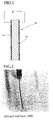
- Fig. 1 is an explanation view showing a schematic structure of an actuator of the present invention;
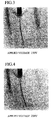
- Fig. 2 is an explanation view on the basis of video images showing deformation of the actuator having a polyurethane sheet member, wherein 100 V is inputted to the actuator;
- Fig. 3 is an explanation view on the basis of video images showing deformation of the actuator having the polyurethane sheet member, wherein 150 V is inputted to the actuator;
- Fig. 4 is an explanation view on the basis of video images showing deformation of the actuator having the polyurethane sheet member, wherein 200 V is inputted to the actuator;
- Fig. 5 is an explanation view on the basis of video images showing deformation of the actuator having the polyurethane sheet member, wherein 300 V is inputted to the actuator;
- Fig. 6 is an explanation view on the basis of video images showing deformation of the actuator having the polyurethane sheet member, wherein 400 V is inputted to the actuator;
- Fig. 7 is an explanation view on the basis of video images showing deformation of the actuator having the polyurethane sheet member, wherein 500 V is inputted to the actuator;
- Fig. 8 is an explanation view on the basis of video images showing deformation of the actuator having the polyurethane sheet member, wherein 600 V is inputted to the actuator;
- Fig. 9 is an explanation view on the basis of video images showing deformation of the actuator having the polyurethane sheet member, wherein 700 V is inputted to the actuator;
- Fig. 10 is an explanation view on the basis of video images showing deformation of the actuator having the polyurethane sheet member, wherein 800 V is inputted to the actuator;
- Fig. 11 is an explanation view on the basis of video images showing deformation of the actuator having the polyurethane sheet member, wherein 900 V is inputted to the actuator;
- Fig. 12 is an explanation view on the basis of video images showing deformation of the actuator having the polyurethane sheet member including electrolyte, wherein 800 V is inputted to the actuator whose electrodes are made of carbon nano fibers;
- Fig. 13 is an explanation view on the basis of video images showing deformation of the actuator having the polyurethane sheet member including electrolyte, wherein 800 V is inputted to the actuator whose electrodes are made of polypyrrole;
- Fig. 14 is an explanation view on the basis of video images showing deformation of the actuator having the polyurethane sheet member including no electrolyte, wherein 800 V is inputted to the actuator whose electrodes are made of carbon nano fibers;
- Fig. 15 is an explanation view on the basis of video images showing deformation of the actuator having the polyurethane sheet member including no electrolyte, wherein 800 V is inputted to the actuator whose electrodes are made of polypyrrole;
- Fig. 16 is an explanation view on the basis of video images showing deformation of the actuator having a silicone film, wherein 800 V is inputted to the actuator;
- Fig. 17 is an explanation view showing the structure of the conventional actuator; and
- Fig. 18 is an explanation view showing the deformation of the conventional actuator.
-
- Preferred embodiments of the present invention will now be described in detail with reference to the accompanying drawings.
- An actuator of the present embodiment is shown in Fig. 1.
- The
actuator 20 has asheet member 22 made of a flexible polymer material. A pair ofelectrodes 24, which are mainly made of carbon nano fibers, are respectively provided on the both side faces of thesheet member 22. - The
electrodes 24 may be formed to cover the whole side faces of thesheet member 22 or formed into prescribed patterns. - In Fig. 1, the
electrodes 24 are formed to cover the whole side faces of thesheet member 22 with uniform thickness. By applying an electric field to one end to anotherelectrode 24, thesheet member 22 is greatly bended. If theelectrodes 24 are patterned, thesheet member 22 can be optionally deformed. - The polymer material of the
sheet member 22 is not limited. For example, polyurethane, especially polyurethane whose soft segment includes polyester may be employed (see Japanese Patent Gazette 2000-49397). - Further, silicone gel, polyvinyl chloride, polyethylene, polypropylene, PET, etc. may be employed as the polymer material.
- Conventionally, in the actuator which is deformed by applying an electric field, a material, whose molecules are oriented by a DC electric field, e.g., polyurethane elastomer including polycarbonate polyol, is employed as the polymer material (see Japanese Patent Gazette No. 7-240544).
- However, in the present embodiment, the improved
electrodes 24 can greatly deform, and polymer materials, whose crystals have no orientation, can be employed. - Note that, a plasticizer may be added to the polymer so as to make a flexible polymer material.
- Preferably, a little electrolyte, e.g., salt, is doped to the polymer material. By adding the electrolyte, an electric current of nA level can pass through the polymer material when the electric field is applied. Namely, the polymer material may have electroconductivity, which is as small as that of a semiconductor. Even in a polymer material having perfect insulativity, e.g., silicone gel, by doping the electrolyte, the material can be relatively greatly deformed when the electric field is applied.
- A material of the
electrodes 24 is carbon nano fibers. For example, carbon nano tubes, which are formed by a vapor growth process, may be employed as the carbon nano fibers. The carbon nano fibers formed by the vapor growth process are very fine fibers having diameter of dozens nm to one hundred and dozens nm and length of less than 20 um. - Preferably, the material of the
electrodes 24 is constituted by carbon nano fibers only. But carbon components, e.g., graphite, carbon, may be added to the carbon nano fibers. - The
electrodes 24, which is formed by the material mainly made of carbon nano fibers, are respectively provided on the both side faces of thesheet member 22, which is made of the flexible polymer material. - Methods of forming the
electrodes 24 will be explained. - Firstly, a first method will be explained. Carbon nano fibers are dispersed in a solvent, e.g., ethanol, to form into paste. The paste is applied on the both side faces of the
sheet member 22 and dried. The dried carbon nano fiber layers become theelectrodes 24. Then, surfaces of theelectrodes 24 are pressed by pressing means, e.g., a roller, so as to completely adhere theelectrodes 24 on the side faces of thesheet member 22. By pressing theelectrode 24, one end of the carbon nano fibers bite into the side faces of thesheet member 22. - Note that, the carbon nano fibers may be coated with layers of electroconductive resin so as to prevent the carbon nano fibers from falling off.
- As described above, the carbon nano fibers are very fine fibers, and the
electrodes 24 are made of many carbon nano fibers. Unlike the conventional electrode made of fine particles of gold, even if thesheet member 22 is greatly deformed, the flexible carbon nano fibers constituting theelectrodes 24 can follow the deformation of thesheet member 22 without separating each other. Namely, the mutual contact of the carbon nano fibers can be maintained while theelectrodes 24 follow the deformation of thesheet member 22. - Since the
electrodes 24 are not cracked and broken even if thesheet member 22 is greatly deformed, function of theelectrodes 24 can be maintained. Therefore, thesheet member 22 can be greatly deform. Note that, thesheet member 22 is originally greatly deformable. - In the present embodiment, the
electrodes 24 are made of the flexible carbon nano fibers, which are capable of following the deformation of thesheet member 22 with maintaining their mutual contact, thesheet member 24 can be maximally deformed. - As described above, one end of the carbon nano fibers can bite into the side faces of the
sheet member 22 by pressing theelectrodes 24 with, for example, the roller. - The inventors think that the ends of the carbon nano fibers biting into the
sheet member 22 emit electrons when the electric field is applied to theelectrodes 24. - Carbon fibers formed by the vapor growth process have been used as fibers for a field electron emitter. Electrons are emitted from sharp ends of the carbon fibers when a high electric field is applied.
- The inventors found that electrons concentratedly emitted from the ends of the carbon nano fibers toward an inner solid or gel part of the
sheet member 22 when the electric field is applied to theelectrodes 24. With this action, thesheet member 22 can be effectively deformed or bended. - The inventors think that electric charges asymmetrically exist in both edge parts of the
sheet member 22, so that one edge part is contracted and the other edge part is extended. Therefore, the polymer material of thesheet member 22 is bended. - As described above, the ends of the carbon nano fibers bite into the
sheet member 22, and electrons are emitted from the ends toward the inner part of thesheet member 22. With this action, electric charges can be effectively charged, so that the asymmetrical existence of electric charges can be promoted. Therefore, thesheet member 22 can be deformed with high responsibility. - The
electrodes 24 may be made of powderlike material (aggregrated) too. In this case, theelectrodes 24 are formed by uniformly scattering the powders onto the side faces of thesheet member 22 and pressing the powders with, for example, a roller. For example, silicone gel has viscous surfaces, the powders can be adhered on the side faces of thesheet member 22 made of the silicone gel so that theelectrodes 24 can be formed. If theelectrodes 24 are pressed, ends of the carbon nano fibers can bite into the side faces of thesheet member 22. - Successively, a second method of forming the
electrodes 24 will be explained. - Powders of a material (carbon nano fibers) are uniformly scattered on a flat steel plate. Then, an electric field is applied to the steel plate. By applying the electric field, the carbon nano fibers stands up. In this state, silicone gel is fed on the upper face of the steel plate and solidified, so that a flexible sub-sheet member having an electrode can be formed on the steel plate. The sub-sheet member having the electrode is peeled from the steel plate. Further, another sub-sheet member having an electrode is formed on an another steel plate by the same manner. Rear faces of the two sub-sheet members, on which no electrodes are formed, are mutually adhered, so that the
actuator 20 having the flexible sheet member and a pair of the electrodes can be formed. - In the both processes, the electrodes can be formed much easier than the conventional electrodes, which are formed by evaporating gold.
- Thickness of the
electrodes 24 are not limited. As described above, the carbon nano fibers are gathered and contact each other, so that mutual contact of the carbon nano fibers can be maintained even if thesheet member 22 is deformed. As far as the carbon nano fibers contact each other, thesheet member 22 is made thinner so as to give higher flexibility. Further, thethin actuator 20 can reduces manufacturing cost. - The thin actuator may be transparent or semitransparent, so they can be used as actuators of many kinds of optical apparatuses.
- Examples of the actuator will be explained.
- Example 1 is respectively shown in Figs. 2-11. Figs. 2-11 are explanation views on the basis of video images showing the deformation of the actuators. In each example, the flexible sheet member was a polyurethane sheet (
width 5 mm,length 20 mm and thickness 0.20 mm), to which sodium acetate was doped. The electrodes were made of carbon nano tubes and formed by the first method. Applied voltage was 100-900 V (0.5-4.5 MV/m). - When the electric field was applied to one end of each actuator, the actuator immediately slightly deforms (see a symbol "On" in each drawing). By increasing the applied voltage, rate of the deformation was accelerated, and degree of the deformation was increased. Note that, in the drawings, symbols "5S" indicate the deformation of the actuators when five seconds elapsed from applying voltage, and symbols "15S" indicate the deformation of the actuators when fifteen seconds elapsed from applying voltage.
- As clearly shown in Figs. 2-11, the sheet members, in each of which the electrodes were formed on the both side faces, were bended like arcs.
- In Fig. 11, 900 V is applied to the electrodes. Curvature of the
maximum deformation 1/R was about 100m-1 (a radius of curvature was about 10 mm). Therefore, a great deformation was attained. - Example 2 is shown in Fig. 12. Fig. 12 is an explanation view on the basis of video images showing the deformation of the actuator. In this example, the flexible sheet member was a polyurethane sheet (
width 5 mm,length 20 mm and thickness 0.20 mm), to which sodium acetate was doped. The electrodes were made of carbon nano tubes. Applied voltage was 800 V (4 MV/m). Fig. 12 shows deformation of the actuator immediately after applying voltage and that after several seconds elapsed from applying voltage. - A comparative example with respect to the Example 2 is shown in Fig. 13. Fig. 13 is an explanation view on the basis of video images showing the deformation of the actuator. In this comparative example, the flexible sheet member was a polyurethane sheet (
width 5 mm,length 20 mm and thickness 0.20 mm), to which sodium acetate was doped. The electrodes were made of polypyrrole. Applied voltage was 800 V (4 MV/m). Fig. 13 shows deformation of the actuator immediately after applying voltage and that after several seconds elapsed from applying voltage. - According to Figs. 12 and 13, the deformation of the actuator, whose electrodes were made of carbon nano fibers, was much greater than that of the actuator, whose electrodes were made of polypyrrole.
- Example 3 is shown in Fig. 14. Fig. 14 is an explanation view on the basis of video images showing the deformation of the actuator. In this example, the flexible sheet member was a polyurethane sheet (
width 5 mm,length 20 mm and thickness 0.20 mm), to which no electrolyte was doped. The electrodes were made of carbon nano tubes. Applied voltage was 800 V (4 MV/m). Fig. 14 shows deformation of the actuator immediately after applying voltage and that after several seconds elapsed from applying voltage. - A comparative example with respect to the Example 3 is shown in Fig. 15. Fig. 15 is an explanation view on the basis of video images showing the deformation of the actuator. In this comparative example, the flexible sheet member was a polyurethane sheet (
width 5 mm,length 20 mm and thickness 0.20 mm), to which no electrolyte was doped. The electrodes were made of polypyrrole. Applied voltage was 800 V (4 MV/m). Fig. 13 shows deformation of the actuator immediately after applying voltage and that after several seconds elapsed from applying voltage. - According to Figs. 14 and 15, the deformation of the actuator, whose electrodes were made of carbon nano fibers, was much greater than that of the actuator, whose electrodes were made of polypyrrole. However, the deformation of the actuators shown in Figs. 12 and 13 were greater than those shown in Figs. 14 and 15 due to the electrolytes.
- Example 4 is shown in Fig. 16. Fig. 16 is an explanation view on the basis of video images showing the deformation of the actuator. In this example, the flexible sheet member was a silicone sheet (
width 5 mm,length 20 mm and thickness 0.20 mm), to which sodium acetate was doped. The electrodes were made of carbon nano tubes. Applied voltage was 800 V (4 MV/m). Fig. 14 shows deformation of the actuator immediately after applying voltage and that after several seconds elapsed from applying voltage. - In the conventional actuator using a silicone sheet, no deformation was visually observed. By doping sodium acetate and employing the electrodes made of carbon nano tubes, the deformation of the actuator was clearly observed.
- The actuator of the present invention uses the deformation of the flexible sheet member, so it cannot be used as a large power actuator. But the actuator can be effectively used for a switch of a minute electric device, an angle-changing mechanism of a reflection mirror, etc.
- The invention may be embodied in other specific forms without departing from the spirit or essential characteristics thereof. The present embodiments are therefore to be considered in all respects as illustrative and not restrictive, the scope of the invention being indicated by the appended claims rather than by he foregoing description and all changes which come within the meaning and range of equivalency of the claims are therefore intended to be embraced therein.
Claims (10)
- An actuator (20),
comprising:characterized in that said electrodes (24) are made of carbon nano fibers.a flexible sheet member (22) made of a polymer material; anda pair of electrodes (24) provided on respective faces of said sheet member (22), - The actuator (20) according to claim 1,
wherein one end of the carbon nano fibers constituting said electrodes (24) bite into said sheet member (22). - The actuator (20) according to claim 1 or 2,
wherein the polymer material is polyurethane resin. - The actuator (20) according to claim 1 or 2,
wherein the polymer material is silicone resin. - A material for electrodes (24) of an actuator (20) of one of claims 1-4 being made of carbon nano fibers.
- Use of carbon nano fibers as electrodes of an actuator.
- A method of making an actuator according to any of claims 1-4 comprising applying carbon nano fibers to a surface of a sheet of polymer material.
- A method of making an actuator according to any of claims 1-4 comprising providing a layer of carbon nano fibers, applying a settable composition over the layer, and setting the composition to form a sheet of polymer material.
- A method according to claim 7 or 8 which initially produces sheets of polymer material having carbon nano fibers only on front faces thereof, the method including a further step of bonding pairs of such sheets together by their rear faces.
- Use as an actuator of a flexible sheet member (22) of polymer material provided with layers of carbon nano fibers (24) on both faces.
Applications Claiming Priority (2)
| Application Number | Priority Date | Filing Date | Title |
|---|---|---|---|
| JP2004027336 | 2004-02-03 | ||
| JP2004027336A JP4277103B2 (en) | 2004-02-03 | 2004-02-03 | Polymer actuator using carbon nanofibers |
Publications (2)
| Publication Number | Publication Date |
|---|---|
| EP1562239A1 true EP1562239A1 (en) | 2005-08-10 |
| EP1562239B1 EP1562239B1 (en) | 2006-12-06 |
Family
ID=34675486
Family Applications (1)
| Application Number | Title | Priority Date | Filing Date |
|---|---|---|---|
| EP20040252033 Expired - Lifetime EP1562239B1 (en) | 2004-02-03 | 2004-04-05 | Polymer actuator comprising electrodes made of carbon nano-fibres |
Country Status (4)
| Country | Link |
|---|---|
| US (1) | US7109643B2 (en) |
| EP (1) | EP1562239B1 (en) |
| JP (1) | JP4277103B2 (en) |
| DE (1) | DE602004003550T2 (en) |
Cited By (3)
| Publication number | Priority date | Publication date | Assignee | Title |
|---|---|---|---|---|
| WO2007029275A1 (en) * | 2005-09-05 | 2007-03-15 | Federico Carpi | Electroactive polymer based actuator, sensor and generator with folded configuration |
| WO2009135328A3 (en) * | 2008-05-09 | 2010-01-14 | Empa | Dielectric traction-pressure actuator |
| WO2007090621A3 (en) * | 2006-02-07 | 2010-11-25 | Micromuscle Ab | Electroactive polymer actuators, applications and methods for fabrication thereof |
Families Citing this family (34)
| Publication number | Priority date | Publication date | Assignee | Title |
|---|---|---|---|---|
| US6812624B1 (en) * | 1999-07-20 | 2004-11-02 | Sri International | Electroactive polymers |
| EP1512215B1 (en) * | 2002-03-18 | 2011-08-17 | SRI International | Electroactive polymer devices for moving fluid |
| JP4272875B2 (en) * | 2002-11-28 | 2009-06-03 | シナノケンシ株式会社 | Electrical contact member |
| CN108425170B (en) * | 2004-11-09 | 2021-02-26 | 得克萨斯大学体系董事会 | Manufacture and use of nanofiber yarns, tapes and sheets |
| JP4691703B2 (en) * | 2005-03-31 | 2011-06-01 | 独立行政法人産業技術総合研究所 | Actuator element and manufacturing method thereof |
| US7833904B2 (en) * | 2005-06-16 | 2010-11-16 | The Trustees Of Columbia University In The City Of New York | Methods for fabricating nanoscale electrodes and uses thereof |
| JP5100060B2 (en) * | 2006-08-24 | 2012-12-19 | 株式会社安川電機 | Stretchable polymer film, method for producing the same, method for producing film with graft polymerized film, and photograft polymerization apparatus |
| JP4771971B2 (en) * | 2007-02-09 | 2011-09-14 | 東海ゴム工業株式会社 | Flexible electrode and electronic device using the same |
| WO2009006318A1 (en) | 2007-06-29 | 2009-01-08 | Artificial Muscle, Inc. | Electroactive polymer transducers for sensory feedback applications |
| JP4948324B2 (en) * | 2007-08-17 | 2012-06-06 | 株式会社クラレ | Electrodevice with polymer flexible electrode |
| JP4948323B2 (en) * | 2007-08-17 | 2012-06-06 | 株式会社クラレ | Electrodevice with polymer flexible electrode |
| WO2009025187A1 (en) * | 2007-08-17 | 2009-02-26 | Kuraray Co., Ltd. | Dielectric material for polymeric actuator, and polymeric actuator using the same |
| DE102008039757A1 (en) * | 2008-08-20 | 2010-02-25 | Fraunhofer-Gesellschaft zur Förderung der angewandten Forschung e.V. | Actuator element and its use |
| JP5487678B2 (en) * | 2009-03-31 | 2014-05-07 | ソニー株式会社 | Actuator |
| EP2239793A1 (en) | 2009-04-11 | 2010-10-13 | Bayer MaterialScience AG | Electrically switchable polymer film structure and use thereof |
| EP2432957A4 (en) * | 2009-05-22 | 2014-08-20 | Proteqt Technologies Inc | Remote-activation lock system and method |
| CN102342013B (en) * | 2009-05-26 | 2014-07-16 | 阿尔卑斯电气株式会社 | polymer actuator device |
| CN102044627A (en) * | 2009-10-22 | 2011-05-04 | 清华大学 | Electrostrictive composite material and electrostrictive element |
| KR101411814B1 (en) | 2010-03-23 | 2014-06-24 | 도카이 고무 고교 가부시키가이샤 | Electroconductive crosslinked product, process for producing same, and transducer, flexible wiring board and electromagnetic-wave shield made by using same |
| CN102201532B (en) * | 2010-03-26 | 2014-04-23 | 清华大学 | Electric actuating material and electric actuating element |
| TWI485896B (en) * | 2010-05-06 | 2015-05-21 | 鴻海精密工業股份有限公司 | Electrically actuated structure and electrically actuated component |
| WO2011151679A1 (en) * | 2010-06-02 | 2011-12-08 | Indian Institute Of Science | Energy harvesting devices using carbon nanotube (cnt)-based electrodes |
| CN101913130B (en) * | 2010-08-25 | 2012-10-10 | 清华大学 | Electrically-actuated clamp holder |
| WO2012118916A2 (en) | 2011-03-01 | 2012-09-07 | Bayer Materialscience Ag | Automated manufacturing processes for producing deformable polymer devices and films |
| TW201250288A (en) | 2011-03-22 | 2012-12-16 | Bayer Materialscience Ag | Electroactive polymer actuator lenticular system |
| KR101264916B1 (en) | 2011-10-26 | 2013-05-22 | 한국과학기술원 | Ionic polymer actuator and method of manufacturing the same |
| WO2013142552A1 (en) | 2012-03-21 | 2013-09-26 | Bayer Materialscience Ag | Roll-to-roll manufacturing processes for producing self-healing electroactive polymer devices |
| KR20150031285A (en) | 2012-06-18 | 2015-03-23 | 바이엘 인텔렉쳐 프로퍼티 게엠베하 | Stretch frame for stretching process |
| KR101373257B1 (en) | 2012-07-10 | 2014-03-13 | 한국과학기술원 | Dry type ionic polymer actuator and method for fabricating the same |
| US9590193B2 (en) | 2012-10-24 | 2017-03-07 | Parker-Hannifin Corporation | Polymer diode |
| WO2014104331A1 (en) | 2012-12-27 | 2014-07-03 | アルプス電気株式会社 | Polymer actuator element |
| WO2014157627A1 (en) | 2013-03-29 | 2014-10-02 | バンドー化学株式会社 | Capacitive sensor sheet and capacitive sensors |
| CN104924701B (en) * | 2015-06-18 | 2017-07-04 | 福建师范大学 | A kind of carbon-based material/polymer composites and preparation method thereof |
| CN108493161A (en) * | 2018-04-16 | 2018-09-04 | 上海集成电路研发中心有限公司 | Semiconductor structure and forming method thereof |
Citations (3)
| Publication number | Priority date | Publication date | Assignee | Title |
|---|---|---|---|---|
| US20020050769A1 (en) * | 1997-02-07 | 2002-05-02 | Sri International | Electroactive polymer electrodes |
| US20020130673A1 (en) * | 2000-04-05 | 2002-09-19 | Sri International | Electroactive polymer sensors |
| US20030030963A1 (en) * | 1996-05-15 | 2003-02-13 | Howard Tennent | Graphitic nanofibers in electrochemical capacitors |
Family Cites Families (7)
| Publication number | Priority date | Publication date | Assignee | Title |
|---|---|---|---|---|
| US4879698A (en) * | 1988-11-03 | 1989-11-07 | Sensor Electronics, Inc. | Piezopolymer actuators |
| JP3270527B2 (en) * | 1992-07-08 | 2002-04-02 | 呉羽化学工業株式会社 | Cylindrical or curved piezoelectric element |
| JP3345730B2 (en) | 1994-02-28 | 2002-11-18 | ニッタ株式会社 | Polyurethane elastomer actuator |
| US5977685A (en) * | 1996-02-15 | 1999-11-02 | Nitta Corporation | Polyurethane elastomer actuator |
| JPH10321482A (en) * | 1997-05-22 | 1998-12-04 | Casio Comput Co Ltd | Electric double layer capacitor |
| US6338547B1 (en) * | 1997-07-15 | 2002-01-15 | Silverbrook Research Pty Ltd | Conductive PTFE bend actuator vented ink jet printing mechanism |
| JP2000049397A (en) | 1998-07-29 | 2000-02-18 | Nitta Ind Corp | Actuator |
-
2004
- 2004-02-03 JP JP2004027336A patent/JP4277103B2/en not_active Expired - Lifetime
- 2004-04-05 EP EP20040252033 patent/EP1562239B1/en not_active Expired - Lifetime
- 2004-04-05 DE DE200460003550 patent/DE602004003550T2/en not_active Expired - Lifetime
- 2004-04-05 US US10/816,875 patent/US7109643B2/en not_active Expired - Fee Related
Patent Citations (3)
| Publication number | Priority date | Publication date | Assignee | Title |
|---|---|---|---|---|
| US20030030963A1 (en) * | 1996-05-15 | 2003-02-13 | Howard Tennent | Graphitic nanofibers in electrochemical capacitors |
| US20020050769A1 (en) * | 1997-02-07 | 2002-05-02 | Sri International | Electroactive polymer electrodes |
| US20020130673A1 (en) * | 2000-04-05 | 2002-09-19 | Sri International | Electroactive polymer sensors |
Non-Patent Citations (1)
| Title |
|---|
| PELRINE R E ET AL: "Electrostriction of polymer dielectrics with compliant electrodes as a means of actuation", SENSORS AND ACTUATORS A, ELSEVIER SEQUOIA S.A., LAUSANNE, CH, vol. 64, no. 1, January 1998 (1998-01-01), pages 77 - 85, XP004102141, ISSN: 0924-4247 * |
Cited By (3)
| Publication number | Priority date | Publication date | Assignee | Title |
|---|---|---|---|---|
| WO2007029275A1 (en) * | 2005-09-05 | 2007-03-15 | Federico Carpi | Electroactive polymer based actuator, sensor and generator with folded configuration |
| WO2007090621A3 (en) * | 2006-02-07 | 2010-11-25 | Micromuscle Ab | Electroactive polymer actuators, applications and methods for fabrication thereof |
| WO2009135328A3 (en) * | 2008-05-09 | 2010-01-14 | Empa | Dielectric traction-pressure actuator |
Also Published As
| Publication number | Publication date |
|---|---|
| EP1562239B1 (en) | 2006-12-06 |
| US20050168113A1 (en) | 2005-08-04 |
| JP4277103B2 (en) | 2009-06-10 |
| JP2005223025A (en) | 2005-08-18 |
| DE602004003550T2 (en) | 2007-09-27 |
| US7109643B2 (en) | 2006-09-19 |
| DE602004003550D1 (en) | 2007-01-18 |
Similar Documents
| Publication | Publication Date | Title |
|---|---|---|
| EP1562239B1 (en) | Polymer actuator comprising electrodes made of carbon nano-fibres | |
| EP3041058B1 (en) | Multilayer transformable device and display device comprising the same | |
| CN105206738B (en) | Electro-active material and electric actuator | |
| US7780496B2 (en) | Method for fabricating electron emitter | |
| US9062663B2 (en) | Actuator | |
| KR101476742B1 (en) | Method for manufacturing nano generator | |
| US20110094671A1 (en) | Method for bonding members | |
| US10777367B2 (en) | Fibrous electrode with buckle structure, method of manufacturing the same, and supercapacitor including the same | |
| US20080014465A1 (en) | Actively switchable nano-structured adhesive | |
| CN111512401B (en) | Transparent electrode manufacturing method | |
| CN101895807A (en) | panel speaker | |
| CN1204568C (en) | Transparent conductive film and production method thereof | |
| KR102065116B1 (en) | Optical transmittance adjusting device, Image apparatus and Method for manufacturing the device | |
| CN102201532A (en) | Electro-actuation material and electro-actuation element | |
| CN114784177A (en) | Flexible gel driver and preparation method thereof | |
| JP5002778B2 (en) | Method for producing transparent conductive film substrate and method for producing transparent laminate | |
| US20180331317A1 (en) | Light emitting device and manufacturing method therefor | |
| US20210025626A1 (en) | Electrostatically actuated device | |
| US10020439B2 (en) | Electrostrictive element | |
| JP7268081B2 (en) | Electrode sheet manufacturing method | |
| KR101613485B1 (en) | Electrostatic force based actuator including inorganic dielectric layer | |
| US10193053B2 (en) | Insulating base material with conductive pattern | |
| WO2020204069A1 (en) | Power generation element and method for manufacturing power generation element | |
| KR101151409B1 (en) | Method of fabricating emitter using carbon nanotube and emitter fabricated using the same | |
| CN113316741B (en) | Electrode mounting method for liquid crystal element |
Legal Events
| Date | Code | Title | Description |
|---|---|---|---|
| PUAI | Public reference made under article 153(3) epc to a published international application that has entered the european phase |
Free format text: ORIGINAL CODE: 0009012 |
|
| AK | Designated contracting states |
Kind code of ref document: A1 Designated state(s): AT BE BG CH CY CZ DE DK EE ES FI FR GB GR HU IE IT LI LU MC NL PL PT RO SE SI SK TR |
|
| AX | Request for extension of the european patent |
Extension state: AL HR LT LV MK |
|
| 17P | Request for examination filed |
Effective date: 20051018 |
|
| RAP1 | Party data changed (applicant data changed or rights of an application transferred) |
Owner name: SHINSHU UNIVERSITY |
|
| AKX | Designation fees paid |
Designated state(s): DE FR GB |
|
| GRAP | Despatch of communication of intention to grant a patent |
Free format text: ORIGINAL CODE: EPIDOSNIGR1 |
|
| GRAS | Grant fee paid |
Free format text: ORIGINAL CODE: EPIDOSNIGR3 |
|
| GRAA | (expected) grant |
Free format text: ORIGINAL CODE: 0009210 |
|
| AK | Designated contracting states |
Kind code of ref document: B1 Designated state(s): DE FR GB |
|
| REG | Reference to a national code |
Ref country code: GB Ref legal event code: FG4D |
|
| REF | Corresponds to: |
Ref document number: 602004003550 Country of ref document: DE Date of ref document: 20070118 Kind code of ref document: P |
|
| ET | Fr: translation filed | ||
| PLBE | No opposition filed within time limit |
Free format text: ORIGINAL CODE: 0009261 |
|
| STAA | Information on the status of an ep patent application or granted ep patent |
Free format text: STATUS: NO OPPOSITION FILED WITHIN TIME LIMIT |
|
| 26N | No opposition filed |
Effective date: 20070907 |
|
| GBPC | Gb: european patent ceased through non-payment of renewal fee |
Effective date: 20080405 |
|
| PG25 | Lapsed in a contracting state [announced via postgrant information from national office to epo] |
Ref country code: GB Free format text: LAPSE BECAUSE OF NON-PAYMENT OF DUE FEES Effective date: 20080405 |
|
| PGFP | Annual fee paid to national office [announced via postgrant information from national office to epo] |
Ref country code: FR Payment date: 20110503 Year of fee payment: 8 Ref country code: DE Payment date: 20110423 Year of fee payment: 8 |
|
| REG | Reference to a national code |
Ref country code: FR Ref legal event code: ST Effective date: 20121228 |
|
| REG | Reference to a national code |
Ref country code: DE Ref legal event code: R119 Ref document number: 602004003550 Country of ref document: DE Effective date: 20121101 |
|
| PG25 | Lapsed in a contracting state [announced via postgrant information from national office to epo] |
Ref country code: FR Free format text: LAPSE BECAUSE OF NON-PAYMENT OF DUE FEES Effective date: 20120430 |
|
| PG25 | Lapsed in a contracting state [announced via postgrant information from national office to epo] |
Ref country code: DE Free format text: LAPSE BECAUSE OF NON-PAYMENT OF DUE FEES Effective date: 20121101 |