EP1562143B1 - Image processing apparatus and control method and program therefor - Google Patents
Image processing apparatus and control method and program therefor Download PDFInfo
- Publication number
- EP1562143B1 EP1562143B1 EP05001834A EP05001834A EP1562143B1 EP 1562143 B1 EP1562143 B1 EP 1562143B1 EP 05001834 A EP05001834 A EP 05001834A EP 05001834 A EP05001834 A EP 05001834A EP 1562143 B1 EP1562143 B1 EP 1562143B1
- Authority
- EP
- European Patent Office
- Prior art keywords
- irradiation field
- area
- shape
- candidate
- candidate area
- Prior art date
- Legal status (The legal status is an assumption and is not a legal conclusion. Google has not performed a legal analysis and makes no representation as to the accuracy of the status listed.)
- Expired - Fee Related
Links
Images


Classifications
-
- A—HUMAN NECESSITIES
- A61—MEDICAL OR VETERINARY SCIENCE; HYGIENE
- A61B—DIAGNOSIS; SURGERY; IDENTIFICATION
- A61B6/00—Apparatus for radiation diagnosis, e.g. combined with radiation therapy equipment
-
- B—PERFORMING OPERATIONS; TRANSPORTING
- B05—SPRAYING OR ATOMISING IN GENERAL; APPLYING FLUENT MATERIALS TO SURFACES, IN GENERAL
- B05B—SPRAYING APPARATUS; ATOMISING APPARATUS; NOZZLES
- B05B1/00—Nozzles, spray heads or other outlets, with or without auxiliary devices such as valves, heating means
- B05B1/22—Spouts
-
- B—PERFORMING OPERATIONS; TRANSPORTING
- B05—SPRAYING OR ATOMISING IN GENERAL; APPLYING FLUENT MATERIALS TO SURFACES, IN GENERAL
- B05B—SPRAYING APPARATUS; ATOMISING APPARATUS; NOZZLES
- B05B17/00—Apparatus for spraying or atomising liquids or other fluent materials, not covered by the preceding groups
- B05B17/08—Fountains
-
- G—PHYSICS
- G06—COMPUTING; CALCULATING OR COUNTING
- G06T—IMAGE DATA PROCESSING OR GENERATION, IN GENERAL
- G06T7/00—Image analysis
- G06T7/10—Segmentation; Edge detection
- G06T7/12—Edge-based segmentation
-
- G—PHYSICS
- G06—COMPUTING; CALCULATING OR COUNTING
- G06T—IMAGE DATA PROCESSING OR GENERATION, IN GENERAL
- G06T7/00—Image analysis
- G06T7/10—Segmentation; Edge detection
- G06T7/194—Segmentation; Edge detection involving foreground-background segmentation
-
- G—PHYSICS
- G06—COMPUTING; CALCULATING OR COUNTING
- G06T—IMAGE DATA PROCESSING OR GENERATION, IN GENERAL
- G06T2207/00—Indexing scheme for image analysis or image enhancement
- G06T2207/10—Image acquisition modality
- G06T2207/10116—X-ray image
-
- G—PHYSICS
- G06—COMPUTING; CALCULATING OR COUNTING
- G06T—IMAGE DATA PROCESSING OR GENERATION, IN GENERAL
- G06T2207/00—Indexing scheme for image analysis or image enhancement
- G06T2207/30—Subject of image; Context of image processing
- G06T2207/30004—Biomedical image processing
Definitions
- the present invention relates to an image processing apparatus and its control method and program which extract an irradiation field area from an image taken by radiography.
- radiographic images are converted into digital image signals, and image processing is performed for the digital image signals to display the resultant images on a display device such as a CRT or print them out.
- a display device such as a CRT or print them out.
- an irradiation field stop is generally used to limit the irradiation field to the necessary area.
- an irradiation field area is extracted in advance to optimize an image processing parameter by eliminating unnecessary information from an image obtained by using an irradiation field stop.
- Such irradiation field stops include rectangular and circular stops, and recognition processing suited to the shapes of various irradiation fields have been proposed.
- X- and Y-axes are set along two adjacent sides of the contour of a rectangular irradiation field, and image data are added/totaled along the X-axis and Y-axis directions.
- the level of the added/totaled data within the irradiation field becomes higher than that of data in any other area outside the irradiation field, to which almost no X-rays are applied.
- Positions on the Y-axis at which the levels of the added/totaled data in the X-axis direction become higher than a predetermined threshold TH and positions on the X-axis at which the levels of the added/totaled data in the Y-axis direction become higher than the predetermined thumbnail TH are calculated.
- the rectangular area surrounded by lines which are located at the calculated positions on the Y-axis and extend in the X-axis direction and lines which are located at the calculated positions on the X-axis and extend in the Y-axis direction is set as an irradiation field area.
- radiographic image data are scanned in an array manner or radially to detect differential signal values.
- Points at which the detected differential signal values are equal to or higher than a threshold TH and pixel signal values nearer to the image center become higher are detected as contour candidate points regarded as points located on the contour of the irradiation field.
- contour candidate points regarded as points located on the contour of the irradiation field.
- two points which are farthest from each other are extracted.
- a circular area having the straight line connecting the extracted two points as a diameter is set as an irradiation field area.
- the method disclosed in Japanese Patent No. 02596744 is available.
- a plurality of edge candidate points located on the end portions of an irradiation field are calculated from predetermined points contained in radiation on the basis of differential values along a plurality of radial directions.
- the area defined by locally connecting these edge candidate points with straight lines is set as an irradiation field area.
- the recognition precision is low in the recognition of irradiation field fields having different shapes.
- the present invention has been made in consideration of the above problem, and has as its object to provide an image processing apparatus and its control method and program which suppress a deterioration in recognition precision in the recognition of irradiation fields having different shapes.
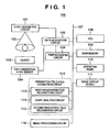
- Fig. 1 is a block diagram showing the arrangement of an X-ray imaging device according to the embodiment of the present invention.
- an X-ray imaging device 100 has an image processing function of performing effective image processing when an X-ray image is to be output onto a filter or monitor.
- the X-ray imaging device 100 includes a data acquisition circuit 105, preprocessing circuit 106, CPU 108, main memory 109, operation panel 110, image display device 111, irradiation field area extraction circuit 112, and image processing circuit 116. These components are connected to each other through a CPU bus 107 so as to be capable of exchanging data.
- the data acquisition circuit 105 and preprocessing circuit 106 are connected to each other, and a two-dimensional X-ray sensor 104 and X-ray generating circuit 101 are connected to the data acquisition circuit 105.
- the irradiation field area extraction circuit 112 includes a first irradiation field recognition circuit 113 serving as a first irradiation field recognition means, a shape analysis circuit 114 serving as a shape analysis means, and a second irradiation field recognition circuit 115 serving as a second irradiation field recognition means.
- the respective circuits are connected to the CPU bus 107.
- the main memory 109 stores various data necessary for processing in the CPU 108, and functions as the working memory of the CPU 108.
- the main memory 109 is specifically a RAM, ROM, or external storage device.
- an external storage device stores various control programs for controlling the X-ray imaging device.
- the CPU 108 controls the overall operation of the apparatus in accordance with the operation of the operation panel 110 (a keyboard, pointing device, touch panel, or the like) by using the main memory 109. With this control, the X-ray imaging device 100 operates as follows.
- the CPU 108 transfers the instruction of capturing an image to the data acquisition circuit 105.
- the CPU 108 executes X-ray imaging by controlling the X-ray generating circuit 101 and two-dimensional X-ray sensor 104.
- the X-ray generating circuit 101 emits an X-ray beam 102 toward an object 103 to be imaged.
- the X-ray beam 102 emitted from the X-ray generating circuit 101 is transmitted through the object 103 while being attenuated, and reaches the two-dimensional X-ray sensor 104.
- the two-dimensional X-ray sensor 104 then outputs an X-ray image signal.
- the object 103 is assumed to be a human body. That is, the X-ray image output from the two-dimensional X-ray sensor 104 is a human body image.
- the data acquisition circuit 105 converts the X-ray image signal output from the two-dimensional X-ray sensor 104 into a predetermined digital signal and supplies it as X-ray image data to the preprocessing circuit 106.
- the preprocessing circuit 106 performs preprocessing such as offset correction processing or gain correction processing for the signal (X-ray image data) from the data acquisition circuit 105.
- the X-ray image data having undergone the preprocessing in the preprocessing circuit 106 is transferred as original image data to the main memory 109 and irradiation field area extraction circuit 112 through the CPU bus 107 under the control of the CPU 108.
- the irradiation field area extraction circuit 112 extracts an irradiation field area by analyzing the original image to generate irradiation field area information.
- the image processing circuit 116 performs various kinds of image processing for the X-ray image signal of the original image on the basis of the irradiation field area information.
- the image processing includes, for example, calculating the histogram of pixel values within the irradiation field area on the basis of the irradiation field area information, and calculating a grayscale processing condition for making the contrast of a region of interest suitable for diagnosis processing. Grayscale processing is then performed for the original image by using the calculated grayscale processing condition.
- the first irradiation field recognition circuit 113 extracts an irradiation field candidate area in the image.
- the shape analysis circuit 114 calculates a feature amount associated with the shape of the irradiation field candidate area extracted by the first irradiation field recognition circuit 113, and discriminates the shape of the irradiation field candidate area on the basis of the feature amount.
- the second irradiation field recognition circuit 115 differently performs irradiation field recognition depending on the feature amount associated with the shape discriminated by the shape analysis circuit 114.
- Fig. 2 is a flowchart showing the flow of processing by the irradiation field area extraction circuit according to the embodiment of the present invention.
- step S201 the first irradiation field recognition circuit 113 extracts irradiation field end candidate points as irradiation field end candidates.
- a method of extracting irradiation field end candidate points is not specifically limited. In this embodiment, however, the method disclosed in Japanese Patent Laid-Open No. 2002-143135 which has already been proposed by the present inventor is used.
- an irradiation field end likelihood is scored in accordance with the pattern of the pixel values of a pixel of interest and neighboring pixels.
- the gradient value of each pixel is then weighted according to the score so as to obtain a feature amount.
- upper, lower, left, and right patterns are separately set, and a point exhibiting a maximum feature amount which is equal to or more than a threshold th is extracted for each line.
- a feature point is detected for each line in the vertical direction. If there is no point exhibiting a feature amount equal to or more than the threshold th on a line, no point is extracted. It suffices if a combination of feature points extracted in the four directions, i.e., up, down, left, and right, is extracted as an irradiation field end candidate point.
- the threshold th may be determined empirically.
- step S202 the first irradiation field recognition circuit 113 extracts an irradiation field candidate area as an irradiation field candidate in the image.
- the area surrounded by the boundary line obtained by connecting the adjacent irradiation field end candidate points extracted in step S201 with straight lines is extracted as an irradiation field candidate area.
- an irradiation field candidate area may be extracted upon smoothing of the boundary line.
- the irradiation field candidate area extracted in this manner becomes an area approximated by a polygon, as shown in Fig. 4 .
- the first irradiation field recognition circuit 113 extracts a rough irradiation field area in an image.
- the present invention is not limited to this, and other irradiation field recognition methods which are not used for the shape information of an overall irradiation field may be used.
- the shape analysis circuit 114 calculates a feature amount associated with the shape of the irradiation field candidate area extracted by the first irradiation field recognition circuit 113.
- This feature amount takes a value of 4 ⁇ , which is the minimum value with respect to a circle, and takes a larger value with an increase in shape complexity. It suffices to use a method other than the above method.
- the feature amount calculated in the above manner reflects the complexity of the shape, and becomes larger when the target is a rectangle than when the target is a circle.
- a circularity is calculated.
- a feature amount associated with squareness instead of circularity may be calculated.
- This feature amount takes a value of 1, which is the maximum value with respect to a rectangular target, and a value of n/4 with respect to a circular target. This value decreases with respect to thinner curved targets.
- a feature amount associated with a shape may be calculated from a plurality of circularities or squarenesses.
- the second irradiation field recognition circuit 115 performs different kinds of irradiation field recognition processing on the basis of information associated with the shape of the irradiation field candidate area (e.g., shape information about a rectangular, circular, or triangular area) calculated by the shape analysis circuit 114.
- information associated with the shape of the irradiation field candidate area e.g., shape information about a rectangular, circular, or triangular area
- step S204 the shape of the irradiation field candidate area is discriminated on the basis of the feature amount associated therewith.
- the feature amount associated with a rectangle is relatively larger than that associated with a circle. It therefore suffices to determine the candidate area is circular if the feature amount is less than a threshold th1, and to determine the candidate area is rectangular if the feature amount is equal to or more than the threshold th1.
- the threshold th1 may be empirically calculated in consideration of the precision of the irradiation field candidate area extracted by the first irradiation field recognition circuit 113.
- step S205 it is determined whether or not the shape of the candidate area is rectangular. If the shape is rectangular (YES in step S205), the flow advances to step S206 to execute irradiation field recognition for rectangles.
- straight lines may be calculated by using Hough transform.
- (x i , y i ) be the coordinates of an extracted irradiation field end candidate point
- p be the distance from a straight line passing through the point and the origin
- ⁇ be the angle defined by the normal to the straight line and the x-axis
- the parameter ⁇ and ⁇ which determine a straight line passing through two irradiation field end candidate points on the x-y plane are given as the coordinates of the intersection of curved lines corresponding to the two irradiation field end candidate points.
- a straight line corresponding to a point at which the maximum number of curved lines intersect is a straight line passing through the maximum number of irradiation field end candidate points. It therefore suffices to set the area surrounded by four straight lines calculated in this manner as a rectangular irradiation field area, as shown in Fig. 6 .
- a straight line determining method other than that described above may be used. For example, a straight line exhibiting a minimum mean square error with each irradiation field end candidate point may be calculated.
- irradiation field recognition for rectangles is not limited to the method described in this embodiment, and other irradiation field recognition methods specialized for rectangles may be used.
- step S205 If it is determined in step S205 that the irradiation field area is not rectangular (NO in step S205), i.e., the irradiation field area is circular in this embodiment, the flow advances to step S207 to execute irradiation field recognition for circles.
- a circle passing through the maximum number of points of the irradiation field end candidate points in all the directions which are extracted in step S201 is calculated.
- parameter values (X, Y) which determine a circle passing through two irradiation field end candidate points on the x-y plane are given as the coordinates of the intersections of curved surfaces corresponding to the two irradiation field end candidate points.
- a circle corresponding to a point at which the maximum number of curved surfaces intersect is a circle passing through the maximum number of irradiation field end candidate points. It therefore suffices to extract the interior of the circle calculated in this manner as an irradiation field area.
- a circle determining method other than that described above may be used. For example, a circle exhibiting a minimum mean square error with each irradiation field end candidate point may be calculated.
- this embodiment may be applied to an ellipse instead of a circle or to a curved line for each local area.
- irradiation field recognition for circles is not limited to the method described in this embodiment; other irradiation field recognition methods specialized for circles may be used.
- irradiation field recognition processing are performed on the basis of feature amounts associated with the shape of the irradiation field candidate areas calculated by the shape analysis circuit 114.
- the present invention is not limited to this.
- information associated with the shape e.g., shape information about a rectangle, circle, triangular, or the like
- irradiation field recognition processing may be performed on the basis of the information.
- irradiation field recognition specialized for the shape of the irradiation field can be performed. This can prevent a deterioration in irradiation field recognition precision.
- a rough irradiation field candidate area is calculated in advance, and the shape of the irradiation field is specified on the basis of the feature amount associated with the shape.
- a rough irradiation field area can be extracted independently of the shape.
- Using at least one of a squareness and a circularity as a feature of an irradiation field candidate area makes it possible to sort circles and rectangles with high precision.
- irradiation field recognition By performing different kinds of irradiation field recognition for circles and rectangles in accordance with the shapes of irradiation fields, irradiation field recognition specialized for each shape can be performed. This can prevent a deterioration in irradiation field recognition precision.
- the shape analysis circuit 114 sorts input images into two shapes, i.e., a rectangle and a circle, and different kinds of irradiation field recognition are performed.
- the embodiment may be configured to sort input images into three or more shapes. For example, when the feature amounts of a rectangle, polygon, and circle are calculated according to equation (1), the feature amounts tend to increase in the order of the circle, polygon, and rectangle.
- Images can therefore be sorted into three shapes by using a threshold TH1 for discriminating a circle and polygon and a threshold TH2 for discriminating a polygon and rectangle. It suffices to perform different kinds of irradiation field recognition with respect to the three shapes sorted in this manner.
- images can be sorted into four or more shapes by preparing a plurality of thresholds. With the above arrangement, reception processing specialized for more shapes can be performed.
- the present invention can be applied to an apparatus comprising a single device or to system constituted by a plurality of devices.
- the invention can be implemented by supplying a software program, which implements the functions of the foregoing embodiments, directly or indirectly to a system or apparatus, reading the supplied program code with a computer of the system or apparatus, and then executing the program code.
- a software program which implements the functions of the foregoing embodiments
- reading the supplied program code with a computer of the system or apparatus, and then executing the program code.
- the mode of implementation need not rely upon a program.
- the program code installed in the computer also implements the present invention.
- the claims of the present invention also cover a computer program for the purpose of implementing the functions of the present invention.
- the program may be executed in any form, such as an object code, a program executed by an interpreter, or scrip data supplied to an operating system.
- Example of storage media that can be used for supplying the program are a floppy disk, a hard disk, an optical disk, a magneto-optical disk, a CD-ROM, a CD-R, a CD-RW, a magnetic tape, a non-volatile type memory card, a ROM, and a DVD (DVD-ROM and a DVD-R).
- a client computer can be connected to a website on the Internet using a browser of the client computer, and the computer program of the present invention or an automatically-installable compressed file of the program can be downloaded to a recording medium such as a hard disk.
- the program of the present invention can be supplied by dividing the program code constituting the program into a plurality of files and downloading the files from different websites.
- a WWW World Wide Web
- a storage medium such as a CD-ROM
- an operating system or the like running on the computer may perform all or a part of the actual processing so that the functions of the foregoing embodiments can be implemented by this processing.
- a CPU or the like mounted on the function expansion board or function expansion unit performs all or a part of the actual processing so that the functions of the foregoing embodiments can be implemented by this processing.
Description
- The present invention relates to an image processing apparatus and its control method and program which extract an irradiation field area from an image taken by radiography.
- With the recent advances in digital technology, radiographic images are converted into digital image signals, and image processing is performed for the digital image signals to display the resultant images on a display device such as a CRT or print them out. In radiography, in order to suppress the influence of X-rays on the outside of a necessary area (irradiation field area) and prevent scattering from the outside of the necessary area to prevent a decrease in contrast, an irradiation field stop is generally used to limit the irradiation field to the necessary area.
- In general, an irradiation field area is extracted in advance to optimize an image processing parameter by eliminating unnecessary information from an image obtained by using an irradiation field stop.
- Such irradiation field stops include rectangular and circular stops, and recognition processing suited to the shapes of various irradiation fields have been proposed.
- For example, as processing for recognizing a rectangular stop, the method disclosed in
Japanese Patent Publication No. 05-049143 - In this method, X- and Y-axes are set along two adjacent sides of the contour of a rectangular irradiation field, and image data are added/totaled along the X-axis and Y-axis directions.
- In this case, the level of the added/totaled data within the irradiation field becomes higher than that of data in any other area outside the irradiation field, to which almost no X-rays are applied. Positions on the Y-axis at which the levels of the added/totaled data in the X-axis direction become higher than a predetermined threshold TH and positions on the X-axis at which the levels of the added/totaled data in the Y-axis direction become higher than the predetermined thumbnail TH are calculated. The rectangular area surrounded by lines which are located at the calculated positions on the Y-axis and extend in the X-axis direction and lines which are located at the calculated positions on the X-axis and extend in the Y-axis direction is set as an irradiation field area.
- As processing for recognizing a circular stop, the method disclosed in
Japanese Patent Laid-Open No. 11-328372 - According to this method, radiographic image data are scanned in an array manner or radially to detect differential signal values. Points at which the detected differential signal values are equal to or higher than a threshold TH and pixel signal values nearer to the image center become higher are detected as contour candidate points regarded as points located on the contour of the irradiation field. Of the plurality of detected contour candidate points, two points which are farthest from each other are extracted. In this case, since the straight line connecting the two points on the circular contour, the distance between which is largest, is regarded as the diameter of the circle, a circular area having the straight line connecting the extracted two points as a diameter is set as an irradiation field area.
- As a method of recognizing an irradiation field independently of the shape of the irradiation field, the method disclosed in
Japanese Patent No. 02596744 - According to the method disclosed in
Japanese Patent Laid-Open No. 05-049143 - In contrast to this, according to the method disclosed in
Japanese Patent Laid-Open No. 11-328372 - According to the method disclosed in
Japanese Patent No. 02596744 JP 2000-023953 US 6,212 291 . However, even an irradiation field whose boundary line should be formed from a curved line, such as a circular irradiation field, is locally approximated by straight lines, and hence the irradiation field recognition result becomes a polygonal shape similar to a circular shape. That is, an irradiation field including a curved line, e.g., a circular irradiation field, can be recognized to some degree by polygonal approximation, but a curved shape cannot be extracted with high precision. - As described above, according to the prior art, the recognition precision is low in the recognition of irradiation field fields having different shapes.
- The present invention has been made in consideration of the above problem, and has as its object to provide an image processing apparatus and its control method and program which suppress a deterioration in recognition precision in the recognition of irradiation fields having different shapes.
- This object is achieved by the method according to claim 1 of extracting an irradiation field area in an image taken by radiography, the image processing apparatus according to claim 10 and the program according to claim 11. The other claims relate to further developments.
- Other features and advantages of the present invention will be apparent from the following description taken in conjunction with the accompanying drawings, in which like reference characters designate the same or similar parts throughout the figures thereof.
- The accompanying drawings, which are incorporated in and constitute a part of the specification, illustrate embodiments of the invention and, together with the description, serve to explain the principles of the invention.
-
Fig. 1 is a block diagram showing the arrangement of an X-ray imaging device according to an embodiment of the present invention; -
Fig. 2 is a flowchart showing the flow of processing by an irradiation field area extraction circuit according to the embodiment of the present invention; -
Fig. 3 is a view showing the processing result obtained by a first irradiation field recognition circuit according to the embodiment of the present invention; -
Fig. 4 is a view showing the processing result obtained by the first irradiation field recognition circuit according to the embodiment of the present invention; -
Fig. 5 is a view showing the processing result obtained by the first irradiation field recognition circuit according to the embodiment of the present invention; -
Fig. 6 is a view showing the processing result obtained by a second irradiation field recognition circuit according to the embodiment of the present invention; and -
Fig. 7 is a view showing the processing result obtained by the second irradiation field recognition circuit according to the embodiment of the present invention. - Preferred embodiment of the present invention will be described in detail in accordance with the accompanying drawings.
- An embodiment of the present invention will be described in detail below with reference to the accompanying drawings.
-
Fig. 1 is a block diagram showing the arrangement of an X-ray imaging device according to the embodiment of the present invention. - As shown in
Fig. 1 , anX-ray imaging device 100 has an image processing function of performing effective image processing when an X-ray image is to be output onto a filter or monitor. TheX-ray imaging device 100 includes adata acquisition circuit 105,preprocessing circuit 106,CPU 108,main memory 109,operation panel 110,image display device 111, irradiation fieldarea extraction circuit 112, andimage processing circuit 116. These components are connected to each other through aCPU bus 107 so as to be capable of exchanging data. - In the
X-ray imaging device 100, thedata acquisition circuit 105 and preprocessingcircuit 106 are connected to each other, and a two-dimensional X-ray sensor 104 andX-ray generating circuit 101 are connected to thedata acquisition circuit 105. The irradiation fieldarea extraction circuit 112 includes a first irradiationfield recognition circuit 113 serving as a first irradiation field recognition means, ashape analysis circuit 114 serving as a shape analysis means, and a second irradiationfield recognition circuit 115 serving as a second irradiation field recognition means. The respective circuits are connected to theCPU bus 107. - In the
X-ray imaging device 100 described above, first of all, themain memory 109 stores various data necessary for processing in theCPU 108, and functions as the working memory of theCPU 108. For example, themain memory 109 is specifically a RAM, ROM, or external storage device. For example, an external storage device stores various control programs for controlling the X-ray imaging device. - The
CPU 108 controls the overall operation of the apparatus in accordance with the operation of the operation panel 110 (a keyboard, pointing device, touch panel, or the like) by using themain memory 109. With this control, theX-ray imaging device 100 operates as follows. - First of all, when an instruction of capturing an image is input from a user through the
operation panel 110, theCPU 108 transfers the instruction of capturing an image to thedata acquisition circuit 105. Upon receiving the instruction to image, theCPU 108 executes X-ray imaging by controlling theX-ray generating circuit 101 and two-dimensional X-ray sensor 104. - In X-ray imaging, first of all, the X-ray generating
circuit 101 emits anX-ray beam 102 toward anobject 103 to be imaged. TheX-ray beam 102 emitted from the X-ray generatingcircuit 101 is transmitted through theobject 103 while being attenuated, and reaches the two-dimensional X-ray sensor 104. The two-dimensional X-ray sensor 104 then outputs an X-ray image signal. In this embodiment, theobject 103 is assumed to be a human body. That is, the X-ray image output from the two-dimensional X-ray sensor 104 is a human body image. - The
data acquisition circuit 105 converts the X-ray image signal output from the two-dimensional X-ray sensor 104 into a predetermined digital signal and supplies it as X-ray image data to thepreprocessing circuit 106. Thepreprocessing circuit 106 performs preprocessing such as offset correction processing or gain correction processing for the signal (X-ray image data) from thedata acquisition circuit 105. The X-ray image data having undergone the preprocessing in thepreprocessing circuit 106 is transferred as original image data to themain memory 109 and irradiation fieldarea extraction circuit 112 through theCPU bus 107 under the control of theCPU 108. - The irradiation field
area extraction circuit 112 extracts an irradiation field area by analyzing the original image to generate irradiation field area information. Theimage processing circuit 116 performs various kinds of image processing for the X-ray image signal of the original image on the basis of the irradiation field area information. The image processing includes, for example, calculating the histogram of pixel values within the irradiation field area on the basis of the irradiation field area information, and calculating a grayscale processing condition for making the contrast of a region of interest suitable for diagnosis processing. Grayscale processing is then performed for the original image by using the calculated grayscale processing condition. - In the irradiation field
area extraction circuit 112, the first irradiationfield recognition circuit 113 extracts an irradiation field candidate area in the image. Theshape analysis circuit 114 calculates a feature amount associated with the shape of the irradiation field candidate area extracted by the first irradiationfield recognition circuit 113, and discriminates the shape of the irradiation field candidate area on the basis of the feature amount. The second irradiationfield recognition circuit 115 differently performs irradiation field recognition depending on the feature amount associated with the shape discriminated by theshape analysis circuit 114. - The operation of the X-ray imaging device according to this embodiment having the above arrangement will be described in detail with reference to
Fig. 2 . -
Fig. 2 is a flowchart showing the flow of processing by the irradiation field area extraction circuit according to the embodiment of the present invention. - A portion associated with irradiation field area extraction processing will be described below with reference to the flow of processing in
Fig. 2 . - The original image obtained by the
preprocessing circuit 106 in the above manner is transferred to the irradiation fieldarea extraction circuit 112 through theCPU bus 107. First of all, in step S201, the first irradiationfield recognition circuit 113 extracts irradiation field end candidate points as irradiation field end candidates. A method of extracting irradiation field end candidate points is not specifically limited. In this embodiment, however, the method disclosed inJapanese Patent Laid-Open No. 2002-143135 - According to this method, an irradiation field end likelihood is scored in accordance with the pattern of the pixel values of a pixel of interest and neighboring pixels. The gradient value of each pixel is then weighted according to the score so as to obtain a feature amount. In this case, upper, lower, left, and right patterns are separately set, and a point exhibiting a maximum feature amount which is equal to or more than a threshold th is extracted for each line.
- When, for example, an upper end is to be detected, a feature point is detected for each line in the vertical direction. If there is no point exhibiting a feature amount equal to or more than the threshold th on a line, no point is extracted. It suffices if a combination of feature points extracted in the four directions, i.e., up, down, left, and right, is extracted as an irradiation field end candidate point. In this case, the threshold th may be determined empirically.
- In step S202, the first irradiation
field recognition circuit 113 extracts an irradiation field candidate area as an irradiation field candidate in the image. In this embodiment, as shown inFig. 3 , the area surrounded by the boundary line obtained by connecting the adjacent irradiation field end candidate points extracted in step S201 with straight lines is extracted as an irradiation field candidate area. - In this case, in order to suppress the influence of an erroneously extracted irradiation field end candidate point, an irradiation field candidate area may be extracted upon smoothing of the boundary line. In a case of a circular irradiation field, the irradiation field candidate area extracted in this manner becomes an area approximated by a polygon, as shown in
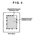
Fig. 4 . - In a case of a rectangular irradiation field, if no irradiation field end candidate point located at a corner of an irradiation field end can be extracted due to the influence of an X-ray shielding object or the like, an area with a loss of a corner may be extracted, as shown in
Fig. 5 . For this reason, although irradiation field candidate area extraction cannot be performed with high precision, an area can be roughly extracted independently of the shape of the area. - As described above, the first irradiation
field recognition circuit 113 extracts a rough irradiation field area in an image. However, the present invention is not limited to this, and other irradiation field recognition methods which are not used for the shape information of an overall irradiation field may be used. - In step S203, the
shape analysis circuit 114 calculates a feature amount associated with the shape of the irradiation field candidate area extracted by the first irradiationfield recognition circuit 113. In this embodiment, for example, a circularity C calculated by equation (1) given below is calculated as a feature amount associated with the shape:

- The feature amount calculated in the above manner reflects the complexity of the shape, and becomes larger when the target is a rectangle than when the target is a circle.
- In this embodiment, a circularity is calculated. However, a feature amount associated with squareness instead of circularity may be calculated. For example, a squareness R may be calculated according to

- In addition, a feature amount associated with a shape may be calculated from a plurality of circularities or squarenesses.
- In steps S204 to S207, the second irradiation
field recognition circuit 115 performs different kinds of irradiation field recognition processing on the basis of information associated with the shape of the irradiation field candidate area (e.g., shape information about a rectangular, circular, or triangular area) calculated by theshape analysis circuit 114. - First of all, in step S204, the shape of the irradiation field candidate area is discriminated on the basis of the feature amount associated therewith. In this embodiment, as described above, since a circularity is calculated as a feature amount, the feature amount associated with a rectangle is relatively larger than that associated with a circle. It therefore suffices to determine the candidate area is circular if the feature amount is less than a threshold th1, and to determine the candidate area is rectangular if the feature amount is equal to or more than the threshold th1. In this case, the threshold th1 may be empirically calculated in consideration of the precision of the irradiation field candidate area extracted by the first irradiation
field recognition circuit 113. - In step S205, it is determined whether or not the shape of the candidate area is rectangular. If the shape is rectangular (YES in step S205), the flow advances to step S206 to execute irradiation field recognition for rectangles.
- Assume that in this embodiment, it is determined that the shape is rectangular. In this case, with regard to irradiation field end candidate points in each of the four directions, i.e., up, down, left, and right, a straight light passing through the maximum number of irradiation field candidate points is calculated.
- More specifically, such straight lines may be calculated by using Hough transform. Letting (xi, yi) be the coordinates of an extracted irradiation field end candidate point, p be the distance from a straight line passing through the point and the origin, and θ be the angle defined by the normal to the straight line and the x-axis, the straight line is represented by

- In this case, the parameter ρ and θ which determine a straight line passing through two irradiation field end candidate points on the x-y plane are given as the coordinates of the intersection of curved lines corresponding to the two irradiation field end candidate points.
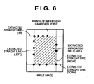
- On the ρ-θ plane, therefore, a straight line corresponding to a point at which the maximum number of curved lines intersect is a straight line passing through the maximum number of irradiation field end candidate points. It therefore suffices to set the area surrounded by four straight lines calculated in this manner as a rectangular irradiation field area, as shown in
Fig. 6 . A straight line determining method other than that described above may be used. For example, a straight line exhibiting a minimum mean square error with each irradiation field end candidate point may be calculated. - By determining an irradiation field area in the above manner, a rectangular irradiation field area can be extracted with high precision even if any feature point of a corner of an irradiation field end cannot be extracted as shown in
Fig. 5 or there is an erroneously extracted feature point. In this case, irradiation field recognition for rectangles is not limited to the method described in this embodiment, and other irradiation field recognition methods specialized for rectangles may be used. - If it is determined in step S205 that the irradiation field area is not rectangular (NO in step S205), i.e., the irradiation field area is circular in this embodiment, the flow advances to step S207 to execute irradiation field recognition for circles.
- In this embodiment, if it is determined that the irradiation field area is circular, a circle passing through the maximum number of points of the irradiation field end candidate points in all the directions which are extracted in step S201 is calculated.
- More specifically, Hough transform is performed by using the circle equation. Letting (xi, yi) be the coordinates of an extracted irradiation field end candidate point, (X, Y) be the center coordinates of the circle, and r be the radius of the circle, the circle is represented by

- In this case, parameter values (X, Y) which determine a circle passing through two irradiation field end candidate points on the x-y plane are given as the coordinates of the intersections of curved surfaces corresponding to the two irradiation field end candidate points.
- In the three-dimensional parameter space defined by (X, Y) and r, a circle corresponding to a point at which the maximum number of curved surfaces intersect is a circle passing through the maximum number of irradiation field end candidate points. It therefore suffices to extract the interior of the circle calculated in this manner as an irradiation field area. A circle determining method other than that described above may be used. For example, a circle exhibiting a minimum mean square error with each irradiation field end candidate point may be calculated. In addition, this embodiment may be applied to an ellipse instead of a circle or to a curved line for each local area.
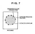
- By determining an irradiation field area in the above manner, since the respective irradiation field end candidate points are smoothly connected as shown in
Fig. 7 , high-precision irradiation field extraction can be performed as compared with the case of polygonal approximation as inFig. 4 . Even if a feature point is erroneously extracted or some feature points are lost, high-precision circle extraction can be performed. In this case, irradiation field recognition for circles is not limited to the method described in this embodiment; other irradiation field recognition methods specialized for circles may be used. - In the above description, different kinds of irradiation field recognition processing are performed on the basis of feature amounts associated with the shape of the irradiation field candidate areas calculated by the
shape analysis circuit 114. However, the present invention is not limited to this. For example, information associated with the shape (e.g., shape information about a rectangle, circle, triangular, or the like) of an irradiation field candidate area is input from theoperation panel 110 serving as an input means, and irradiation field recognition processing may be performed on the basis of the information. - As has been described above, according to this embodiment, since an irradiation field is recognized on the basis of information associated with the shape of the irradiation field, irradiation field recognition specialized for the shape of the irradiation field can be performed. This can prevent a deterioration in irradiation field recognition precision.
- According to this embodiment, a rough irradiation field candidate area is calculated in advance, and the shape of the irradiation field is specified on the basis of the feature amount associated with the shape. This makes it possible to automatically perform irradiation field recognition specialized for the shape of the irradiation field. Therefore, a deterioration in irradiation field recognition precision can be prevented.
- By recognizing the area surrounded by a plurality of irradiation field end candidate points as an irradiation field area, a rough irradiation field area can be extracted independently of the shape.
- Using at least one of a squareness and a circularity as a feature of an irradiation field candidate area makes it possible to sort circles and rectangles with high precision.
- By performing different kinds of irradiation field recognition for circles and rectangles in accordance with the shapes of irradiation fields, irradiation field recognition specialized for each shape can be performed. This can prevent a deterioration in irradiation field recognition precision.
- Using curved lines when it is determined that an irradiation field candidate area is circular makes it possible to perform irradiation field area extraction with respect to a circular irradiation field whose boundary is a curved line. This can prevent a deterioration in irradiation field exaction precision.
- Using straight lines when it is determined that an irradiation field candidate area is rectangular makes it possible to perform irradiation field area extraction with respect to a rectangular irradiation field whose boundary is comprised of straight lines. This can prevent a deterioration in irradiation field exaction precision.
- In this embodiment, the
shape analysis circuit 114 sorts input images into two shapes, i.e., a rectangle and a circle, and different kinds of irradiation field recognition are performed. However, the embodiment may be configured to sort input images into three or more shapes. For example, when the feature amounts of a rectangle, polygon, and circle are calculated according to equation (1), the feature amounts tend to increase in the order of the circle, polygon, and rectangle. - Images can therefore be sorted into three shapes by using a threshold TH1 for discriminating a circle and polygon and a threshold TH2 for discriminating a polygon and rectangle. It suffices to perform different kinds of irradiation field recognition with respect to the three shapes sorted in this manner. In addition, as is obvious, images can be sorted into four or more shapes by preparing a plurality of thresholds. With the above arrangement, reception processing specialized for more shapes can be performed.
- Note that the present invention can be applied to an apparatus comprising a single device or to system constituted by a plurality of devices.
- Furthermore, the invention can be implemented by supplying a software program, which implements the functions of the foregoing embodiments, directly or indirectly to a system or apparatus, reading the supplied program code with a computer of the system or apparatus, and then executing the program code. In this case, so long as the system or apparatus has the functions of the program, the mode of implementation need not rely upon a program.
- Accordingly, since the functions of the present invention are implemented by computer, the program code installed in the computer also implements the present invention. In other words, the claims of the present invention also cover a computer program for the purpose of implementing the functions of the present invention.
- In this case, so long as the system or apparatus has the functions of the program, the program may be executed in any form, such as an object code, a program executed by an interpreter, or scrip data supplied to an operating system.
- Example of storage media that can be used for supplying the program are a floppy disk, a hard disk, an optical disk, a magneto-optical disk, a CD-ROM, a CD-R, a CD-RW, a magnetic tape, a non-volatile type memory card, a ROM, and a DVD (DVD-ROM and a DVD-R).
- As for the method of supplying the program, a client computer can be connected to a website on the Internet using a browser of the client computer, and the computer program of the present invention or an automatically-installable compressed file of the program can be downloaded to a recording medium such as a hard disk. Further, the program of the present invention can be supplied by dividing the program code constituting the program into a plurality of files and downloading the files from different websites. In other words, a WWW (World Wide Web) server that downloads, to multiple users, the program files that implement the functions of the present invention by computer is also covered by the claims of the present invention.
- It is also possible to encrypt and store the program of the present invention on a storage medium such as a CD-ROM, distribute the storage medium to users, allow users who meet certain requirements to download decryption key information from a website via the Internet, and allow these users to decrypt the encrypted program by using the key information, whereby the program is installed in the user computer.
- Besides the cases where the aforementioned functions according to the embodiments are implemented by executing the read program by computer, an operating system or the like running on the computer may perform all or a part of the actual processing so that the functions of the foregoing embodiments can be implemented by this processing.
- Furthermore, after the program read from the storage medium is written to a function expansion board inserted into the computer or to a memory provided in a function expansion unit connected to the computer, a CPU or the like mounted on the function expansion board or function expansion unit performs all or a part of the actual processing so that the functions of the foregoing embodiments can be implemented by this processing.
- As many apparently widely different embodiments of the present invention can be made, it is to be understood that the invention is not limited to the specific embodiments thereof, but defined in the appended claims.
Claims (11)
- A method of extracting an irradiation field area in an image taken by radiography, comprising, in the subsequent order:a first irradiation field recognition step of extracting an irradiation field candidate area in the image by extracting a plurality of irradiation field end candidate points regarded as located at end portions of an irradiation field;a shape analysis step of calculating at least one of a squareness and a circularity as a feature amount associated with a shape of the irradiation field candidate area extracted in the first irradiation field recognition step and determining a shape of the irradiation field candidate area on the basis of the feature amount as one of a circle, or a rectangle, or a polygon; anda second irradiation field recognition step of performing irradiation field recognition on the basis of information associated with the shape determined in the shape analysis step and applying a circle to the plurality of irradiation field end candidate points when the determined shape Is a circle;characterized in that, when the shape analysis step determines that the shape is a rectangle, the second irradiation field recognition step comprises executing irradiation field recognition specifically for rectangles bysetting that the irradiation field area is an area surrounded by four straight lines, one for each of an up, down, left, and right direction, andcalculating the straight line of each direction based on the irradiation field end candidate points of the respective direction.
- The method according to claim 1, wherein the shape analysis step determines the shape of the entire irradiation field candidate area as either a circle or a rectangle.
- The method according to claims 1 or 2, wherein said shape analysis step includes
calculating said feature amount in terms of a ratio between an area size (A) of the irradiation field candidate area and a value associated with the boundary of said area, and
comparing the calculated feature amount to a predetermined threshold value. - The method according to claim 3, wherein said shape analysis step calculates a circularity C of the irradiation field candidate area in terms of

where P is the perimeter of the irradiation field candidate area and A is the area size of the irradiation field candidate area. - The method according to claim 3, wherein said shape analysis step calculates a circularity C of the irradiation field candidate area in terms of

where di (i = 1,2, .. N) are shortest distances from N pixels within the irradiation field area to the boundary line, and A is the area size of the irradiation field candidate area. - The method according to claim 3, wherein said shape analysis step calculates the squareness R of the irradiation field candidate area in terms of

where MER is the area of the minimum rectangle surrounding the irradiation field candidate area and A is the area size of the irradiation field candidate area. - The method according to any one of claims 1 to 6, wherein, in the second irradiation field recognition step, the straight lines are each calculated to pass through a maximum number of, or to exhibit a minimum mean square error with the irradiation field end candidate points in the respective direction.
- The method according to any one of claims 1 to 7, wherein extracting and grouping the plurality of irradiation field end candidate points includes
calculating a feature amount for each of the irradiation field end candidate points by scoring an irradiation field end likelihood with a pattern of pixel values of a pixel of interest and neighbouring pixels, and
comparing the calculated feature amount to a predetermined threshold value - The method according to any one of claims 1 to 8, wherein, in the first irradiation field recognition step, the irradiation field candidate area Is extracted as an area surrounded by a boundary line obtained by connecting the adjacent irradiation field end candidate points with straight lines, optionally followed by smoothing of the boundary line.
- An image processing apparatus, adapted to extract an irradiation field area in an image taken by radiography according to the method as claimed in any one of claims 1 to 9.
- A program for realizing control of an image processing apparatus, comprising a program code for extracting an irradiation field area in an image taken by radiography according to the method as claimed in any one of claims 1 to 9.
Applications Claiming Priority (2)
| Application Number | Priority Date | Filing Date | Title |
|---|---|---|---|
| JP2004028532A JP4708712B2 (en) | 2004-02-04 | 2004-02-04 | Image processing apparatus, control method therefor, and program |
| JP2004028532 | 2004-02-04 |
Publications (3)
| Publication Number | Publication Date |
|---|---|
| EP1562143A2 EP1562143A2 (en) | 2005-08-10 |
| EP1562143A3 EP1562143A3 (en) | 2006-02-15 |
| EP1562143B1 true EP1562143B1 (en) | 2012-04-25 |
Family
ID=34675510
Family Applications (1)
| Application Number | Title | Priority Date | Filing Date |
|---|---|---|---|
| EP05001834A Expired - Fee Related EP1562143B1 (en) | 2004-02-04 | 2005-01-28 | Image processing apparatus and control method and program therefor |
Country Status (5)
| Country | Link |
|---|---|
| US (1) | US7570792B2 (en) |
| EP (1) | EP1562143B1 (en) |
| JP (1) | JP4708712B2 (en) |
| KR (1) | KR100719469B1 (en) |
| CN (1) | CN100366224C (en) |
Families Citing this family (17)
| Publication number | Priority date | Publication date | Assignee | Title |
|---|---|---|---|---|
| JP4484579B2 (en) * | 2004-05-11 | 2010-06-16 | キヤノン株式会社 | Image processing apparatus and method, and program |
| DE102004041521A1 (en) * | 2004-08-27 | 2006-03-02 | Robert Bosch Gmbh | Method and device for evaluating driving situations |
| JP2007185209A (en) * | 2006-01-11 | 2007-07-26 | Hitachi Medical Corp | X-ray imaging apparatus |
| US8098936B2 (en) | 2007-01-12 | 2012-01-17 | Seiko Epson Corporation | Method and apparatus for detecting objects in an image |
| JP4854546B2 (en) * | 2007-03-06 | 2012-01-18 | キヤノン株式会社 | Image processing apparatus and image processing method |
| US20090124579A1 (en) * | 2007-11-09 | 2009-05-14 | University Of South Carolina | Systems and Methods For Determination of Compounds for Stimulation or Inhibition of Neocalcification |
| JP5464799B2 (en) | 2007-11-16 | 2014-04-09 | キヤノン株式会社 | Image processing apparatus, image processing method, and program |
| JP5181704B2 (en) | 2008-02-07 | 2013-04-10 | 日本電気株式会社 | Data processing apparatus, posture estimation system, posture estimation method and program |
| JP5197140B2 (en) | 2008-05-07 | 2013-05-15 | キヤノン株式会社 | X-ray fluoroscopic apparatus, moving image processing method, program, and storage medium |
| JP5333607B2 (en) * | 2009-12-29 | 2013-11-06 | 株式会社島津製作所 | Radiation image processing apparatus and radiation image processing program |
| JP5631030B2 (en) | 2010-03-16 | 2014-11-26 | キヤノン株式会社 | Radiation image processing apparatus, image processing method, radiation imaging system, and program |
| JP5438647B2 (en) * | 2010-03-31 | 2014-03-12 | 富士フイルム株式会社 | Radiation imaging system |
| JP5567944B2 (en) * | 2010-08-31 | 2014-08-06 | 富士フイルム株式会社 | Radiation imaging apparatus and method, and program |
| EP2500864B1 (en) * | 2011-03-15 | 2020-05-06 | Agfa Nv | Irradiation field recognition |
| US9105087B2 (en) * | 2012-07-20 | 2015-08-11 | Lawrence Livermore National Security, Llc | System for uncollimated digital radiography |
| US20140264078A1 (en) * | 2013-03-12 | 2014-09-18 | Agfa Healthcare Nv | Radiation Image Read-Out and Cropping System |
| JP7134017B2 (en) * | 2018-08-14 | 2022-09-09 | キヤノン株式会社 | Image processing device, image processing method, and program |
Family Cites Families (32)
| Publication number | Priority date | Publication date | Assignee | Title |
|---|---|---|---|---|
| JPS6088538A (en) * | 1983-10-20 | 1985-05-18 | 富士写真フイルム株式会社 | X-ray photographing apparatus |
| JPS6215537A (en) * | 1985-07-15 | 1987-01-23 | Fuji Photo Film Co Ltd | Determining method for readout condition of radiation image information |
| US4868843A (en) * | 1986-09-10 | 1989-09-19 | Varian Associates, Inc. | Multileaf collimator and compensator for radiotherapy machines |
| US4970393A (en) * | 1986-11-25 | 1990-11-13 | Fuji Photo Film Co., Ltd. | Irradiation field recognizing method, and method of adjusting image processing conditions using the same |
| JP2596744B2 (en) | 1987-04-16 | 1997-04-02 | 富士写真フイルム株式会社 | Radiation field recognition method |
| JPH0821073B2 (en) * | 1988-03-31 | 1996-03-04 | 富士写真フイルム株式会社 | Irradiation field diaphragm presence / absence determination method |
| EP0726542B1 (en) * | 1990-04-18 | 1999-09-15 | Fuji Photo Film Co., Ltd. | Method and apparatus for adjusting read-out conditions and/or image processing conditions for radiation images, radiation image read-out apparatus, and radiation image analyzing method and apparatus |
| US5828775A (en) * | 1990-04-18 | 1998-10-27 | Fuji Photo Film Co., Ltd. | Method and apparatus for adjusting read-out conditions and/or image processing conditions for radiation images , radiation image read-out apparatus, and radiation image analyzing method and apparatus |
| JPH0549143A (en) | 1991-08-12 | 1993-02-26 | Sekisui Chem Co Ltd | Cable containing type plinth |
| JP3499254B2 (en) * | 1993-06-04 | 2004-02-23 | 富士写真フイルム株式会社 | Image data compression processing method |
| JP3380609B2 (en) * | 1993-12-24 | 2003-02-24 | コニカ株式会社 | Radiation image field extraction device |
| JPH0997321A (en) * | 1995-09-29 | 1997-04-08 | Fuji Photo Film Co Ltd | Image display method |
| JP3707871B2 (en) * | 1996-08-16 | 2005-10-19 | 富士写真フイルム株式会社 | Radiation image processing method and apparatus |
| JP3609211B2 (en) * | 1996-08-29 | 2005-01-12 | 富士写真フイルム株式会社 | Radiation image processing device |
| JPH10162156A (en) * | 1996-11-28 | 1998-06-19 | Fuji Photo Film Co Ltd | Irradiation filed recognition device and radiation image processor |
| US5901240A (en) * | 1996-12-12 | 1999-05-04 | Eastman Kodak Company | Method for detecting the collimation field in a digital radiography |
| JP3923131B2 (en) * | 1997-03-31 | 2007-05-30 | 富士フイルム株式会社 | Radiation field irradiation method and apparatus, and blackening processing method and apparatus |
| JP3397652B2 (en) * | 1997-09-22 | 2003-04-21 | キヤノン株式会社 | Image determining method, image determining apparatus, and storage medium |
| JP3832974B2 (en) * | 1998-08-25 | 2006-10-11 | キヤノン株式会社 | Irradiation area extraction method, irradiation area extraction apparatus, and computer-readable storage medium |
| US6317510B1 (en) * | 1997-12-19 | 2001-11-13 | Fuji Photo Film Co., Ltd. | Blackening processing method and apparatus |
| KR100292348B1 (en) * | 1997-12-29 | 2001-06-01 | 윤종용 | Initializing method according to the feature of a detected shape in block matching algorithm to apply genetic algorithm |
| US6212291B1 (en) * | 1998-01-29 | 2001-04-03 | Eastman Kodak Company | Method for recognizing multiple irradiation fields in digital radiography |
| JP2000023953A (en) * | 1998-04-30 | 2000-01-25 | Konica Corp | Irradiation field recognizing method |
| JPH11328372A (en) | 1998-05-18 | 1999-11-30 | Konica Corp | Method and device for recognizing irreadiation field |
| JP4280334B2 (en) * | 1998-08-25 | 2009-06-17 | キヤノン株式会社 | Irradiation squeezing presence / absence determination device, method, and computer-readable storage medium |
| JP2000271107A (en) * | 1999-03-19 | 2000-10-03 | Canon Inc | Device, system and method for processing image, and storage medium |
| JP3854766B2 (en) * | 1999-12-06 | 2006-12-06 | キヤノン株式会社 | Image processing apparatus, image processing system, image arrangement method, and computer-readable recording medium |
| JP4560202B2 (en) | 2000-11-10 | 2010-10-13 | キヤノン株式会社 | Image processing apparatus, image processing system, image processing method, and storage medium |
| US7142705B2 (en) * | 2001-05-01 | 2006-11-28 | Canon Kabushiki Kaisha | Radiation image processing apparatus, image processing system, radiation image processing method, storage medium, and program |
| US6961454B2 (en) * | 2001-10-04 | 2005-11-01 | Siemens Corporation Research, Inc. | System and method for segmenting the left ventricle in a cardiac MR image |
| JP4307877B2 (en) * | 2003-03-20 | 2009-08-05 | 富士フイルム株式会社 | Image processing apparatus and image processing method |
| JP4484579B2 (en) | 2004-05-11 | 2010-06-16 | キヤノン株式会社 | Image processing apparatus and method, and program |
-
2004
- 2004-02-04 JP JP2004028532A patent/JP4708712B2/en not_active Expired - Fee Related
-
2005
- 2005-01-28 EP EP05001834A patent/EP1562143B1/en not_active Expired - Fee Related
- 2005-01-31 US US11/045,283 patent/US7570792B2/en not_active Expired - Fee Related
- 2005-02-04 KR KR1020050010382A patent/KR100719469B1/en not_active IP Right Cessation
- 2005-02-04 CN CNB2005100079796A patent/CN100366224C/en not_active Expired - Fee Related
Also Published As
| Publication number | Publication date |
|---|---|
| KR20060041700A (en) | 2006-05-12 |
| CN100366224C (en) | 2008-02-06 |
| JP2005218581A (en) | 2005-08-18 |
| EP1562143A2 (en) | 2005-08-10 |
| EP1562143A3 (en) | 2006-02-15 |
| US7570792B2 (en) | 2009-08-04 |
| KR100719469B1 (en) | 2007-05-17 |
| CN1650806A (en) | 2005-08-10 |
| JP4708712B2 (en) | 2011-06-22 |
| US20050169534A1 (en) | 2005-08-04 |
Similar Documents
| Publication | Publication Date | Title |
|---|---|---|
| EP1562143B1 (en) | Image processing apparatus and control method and program therefor | |
| KR100903595B1 (en) | Radiation area extracting method and image processing apparatus | |
| US6839466B2 (en) | Detecting overlapping images in an automatic image segmentation device with the presence of severe bleeding | |
| JP3833153B2 (en) | Image processing method and apparatus | |
| EP3176751B1 (en) | Information processing device, information processing method, computer-readable recording medium, and inspection system | |
| JP2002133426A (en) | Ruled line extracting device for extracting ruled line from multiple image | |
| JP4964171B2 (en) | Target region extraction method, apparatus, and program | |
| WO2009094446A1 (en) | Method and apparatus for cropping images | |
| US20100284579A1 (en) | Abnormal shadow candidate detecting method and abnormal shadow candidate detecting apparatus | |
| EP3843038B1 (en) | Image processing method and system | |
| US6885770B2 (en) | Irradiation field extracting method and apparatus and recording medium | |
| JP2007202811A (en) | Radiation field recognition unit, radiation field recognition method, and program therefor | |
| US20030169912A1 (en) | Image processing method and apparatus and recording medium | |
| US8073232B2 (en) | Method and system for diaphragm segmentation in chest X-ray radiographs | |
| JP5845139B2 (en) | Graphic detection processing apparatus, graphic detection processing method, and graphic detection processing program | |
| JPH1196380A (en) | Feature amount extracting method, feature extracting device, image discriminating method, image discriminating device and storage medium | |
| JPH1189823A (en) | Method and device for discriminating image and storage medium | |
| JP2002133396A (en) | Abnormal shadow candidate detector and image processor | |
| JP3832974B2 (en) | Irradiation area extraction method, irradiation area extraction apparatus, and computer-readable storage medium | |
| JP2006288467A (en) | Device and method for judging irradiation field and its program | |
| US7400778B2 (en) | Diagnosis support apparatus and image processing method | |
| JP3220226B2 (en) | Character string direction determination method | |
| JPH11296675A (en) | Image discrimination method, image discrimination device and storage medium | |
| CN116704517A (en) | Character recognition method in therapy control system display, electronic equipment and storage medium | |
| CN117746442A (en) | Handwritten signature verification method and device and electronic equipment |
Legal Events
| Date | Code | Title | Description |
|---|---|---|---|
| PUAI | Public reference made under article 153(3) epc to a published international application that has entered the european phase |
Free format text: ORIGINAL CODE: 0009012 |
|
| AK | Designated contracting states |
Kind code of ref document: A2 Designated state(s): AT BE BG CH CY CZ DE DK EE ES FI FR GB GR HU IE IS IT LI LT LU MC NL PL PT RO SE SI SK TR |
|
| AX | Request for extension of the european patent |
Extension state: AL BA HR LV MK YU |
|
| PUAL | Search report despatched |
Free format text: ORIGINAL CODE: 0009013 |
|
| AK | Designated contracting states |
Kind code of ref document: A3 Designated state(s): AT BE BG CH CY CZ DE DK EE ES FI FR GB GR HU IE IS IT LI LT LU MC NL PL PT RO SE SI SK TR |
|
| AX | Request for extension of the european patent |
Extension state: AL BA HR LV MK YU |
|
| 17P | Request for examination filed |
Effective date: 20060816 |
|
| AKX | Designation fees paid |
Designated state(s): BE DE FR GB NL |
|
| 17Q | First examination report despatched |
Effective date: 20080508 |
|
| GRAP | Despatch of communication of intention to grant a patent |
Free format text: ORIGINAL CODE: EPIDOSNIGR1 |
|
| GRAS | Grant fee paid |
Free format text: ORIGINAL CODE: EPIDOSNIGR3 |
|
| GRAA | (expected) grant |
Free format text: ORIGINAL CODE: 0009210 |
|
| AK | Designated contracting states |
Kind code of ref document: B1 Designated state(s): BE DE FR GB NL |
|
| REG | Reference to a national code |
Ref country code: GB Ref legal event code: FG4D |
|
| REG | Reference to a national code |
Ref country code: DE Ref legal event code: R096 Ref document number: 602005033801 Country of ref document: DE Effective date: 20120621 |
|
| REG | Reference to a national code |
Ref country code: NL Ref legal event code: T3 |
|
| PG25 | Lapsed in a contracting state [announced via postgrant information from national office to epo] |
Ref country code: BE Free format text: LAPSE BECAUSE OF FAILURE TO SUBMIT A TRANSLATION OF THE DESCRIPTION OR TO PAY THE FEE WITHIN THE PRESCRIBED TIME-LIMIT Effective date: 20120425 |
|
| PLBE | No opposition filed within time limit |
Free format text: ORIGINAL CODE: 0009261 |
|
| STAA | Information on the status of an ep patent application or granted ep patent |
Free format text: STATUS: NO OPPOSITION FILED WITHIN TIME LIMIT |
|
| 26N | No opposition filed |
Effective date: 20130128 |
|
| REG | Reference to a national code |
Ref country code: DE Ref legal event code: R097 Ref document number: 602005033801 Country of ref document: DE Effective date: 20130128 |
|
| PGFP | Annual fee paid to national office [announced via postgrant information from national office to epo] |
Ref country code: NL Payment date: 20140115 Year of fee payment: 10 |
|
| PGFP | Annual fee paid to national office [announced via postgrant information from national office to epo] |
Ref country code: FR Payment date: 20140124 Year of fee payment: 10 |
|
| PGFP | Annual fee paid to national office [announced via postgrant information from national office to epo] |
Ref country code: GB Payment date: 20140123 Year of fee payment: 10 |
|
| REG | Reference to a national code |
Ref country code: NL Ref legal event code: V1 Effective date: 20150801 |
|
| GBPC | Gb: european patent ceased through non-payment of renewal fee |
Effective date: 20150128 |
|
| PG25 | Lapsed in a contracting state [announced via postgrant information from national office to epo] |
Ref country code: NL Free format text: LAPSE BECAUSE OF NON-PAYMENT OF DUE FEES Effective date: 20150801 |
|
| PG25 | Lapsed in a contracting state [announced via postgrant information from national office to epo] |
Ref country code: GB Free format text: LAPSE BECAUSE OF NON-PAYMENT OF DUE FEES Effective date: 20150128 |
|
| REG | Reference to a national code |
Ref country code: FR Ref legal event code: ST Effective date: 20150930 |
|
| PG25 | Lapsed in a contracting state [announced via postgrant information from national office to epo] |
Ref country code: FR Free format text: LAPSE BECAUSE OF NON-PAYMENT OF DUE FEES Effective date: 20150202 |
|
| PGFP | Annual fee paid to national office [announced via postgrant information from national office to epo] |
Ref country code: DE Payment date: 20160131 Year of fee payment: 12 |
|
| REG | Reference to a national code |
Ref country code: DE Ref legal event code: R119 Ref document number: 602005033801 Country of ref document: DE |
|
| PG25 | Lapsed in a contracting state [announced via postgrant information from national office to epo] |
Ref country code: DE Free format text: LAPSE BECAUSE OF NON-PAYMENT OF DUE FEES Effective date: 20170801 |