EP1562024A2 - Variable-reluctance resolver and method and apparatus for manufacturing the same - Google Patents
Variable-reluctance resolver and method and apparatus for manufacturing the same Download PDFInfo
- Publication number
- EP1562024A2 EP1562024A2 EP04014515A EP04014515A EP1562024A2 EP 1562024 A2 EP1562024 A2 EP 1562024A2 EP 04014515 A EP04014515 A EP 04014515A EP 04014515 A EP04014515 A EP 04014515A EP 1562024 A2 EP1562024 A2 EP 1562024A2
- Authority
- EP
- European Patent Office
- Prior art keywords
- salient pole
- rotor
- rotary shaft
- die
- bulge
- Prior art date
- Legal status (The legal status is an assumption and is not a legal conclusion. Google has not performed a legal analysis and makes no representation as to the accuracy of the status listed.)
- Withdrawn
Links
- 238000000034 method Methods 0.000 title claims description 32
- 238000004519 manufacturing process Methods 0.000 title claims description 27
- 238000005242 forging Methods 0.000 claims description 32
- 238000005245 sintering Methods 0.000 claims description 11
- 238000005266 casting Methods 0.000 claims description 7
- 230000008569 process Effects 0.000 description 11
- 230000015572 biosynthetic process Effects 0.000 description 9
- 238000004804 winding Methods 0.000 description 9
- 238000005520 cutting process Methods 0.000 description 7
- 239000000463 material Substances 0.000 description 7
- 229910000976 Electrical steel Inorganic materials 0.000 description 6
- XEEYBQQBJWHFJM-UHFFFAOYSA-N Iron Chemical compound [Fe] XEEYBQQBJWHFJM-UHFFFAOYSA-N 0.000 description 6
- 239000000696 magnetic material Substances 0.000 description 6
- 230000004907 flux Effects 0.000 description 5
- 238000003754 machining Methods 0.000 description 5
- 229910000975 Carbon steel Inorganic materials 0.000 description 4
- 208000015943 Coeliac disease Diseases 0.000 description 4
- 239000010962 carbon steel Substances 0.000 description 4
- 230000008859 change Effects 0.000 description 3
- 230000007423 decrease Effects 0.000 description 3
- 229910052742 iron Inorganic materials 0.000 description 3
- 239000006247 magnetic powder Substances 0.000 description 3
- 239000002184 metal Substances 0.000 description 3
- 229910052751 metal Inorganic materials 0.000 description 3
- 230000009467 reduction Effects 0.000 description 3
- 238000009966 trimming Methods 0.000 description 3
- 239000000853 adhesive Substances 0.000 description 2
- 230000001070 adhesive effect Effects 0.000 description 2
- 229910045601 alloy Inorganic materials 0.000 description 2
- 239000000956 alloy Substances 0.000 description 2
- 238000006243 chemical reaction Methods 0.000 description 2
- 229910000889 permalloy Inorganic materials 0.000 description 2
- 238000003825 pressing Methods 0.000 description 2
- 238000004080 punching Methods 0.000 description 2
- 229910001018 Cast iron Inorganic materials 0.000 description 1
- 229910001141 Ductile iron Inorganic materials 0.000 description 1
- 229910001296 Malleable iron Inorganic materials 0.000 description 1
- -1 S45C) Inorganic materials 0.000 description 1
- 229910000831 Steel Inorganic materials 0.000 description 1
- 230000001133 acceleration Effects 0.000 description 1
- 230000009471 action Effects 0.000 description 1
- 230000002411 adverse Effects 0.000 description 1
- 238000005452 bending Methods 0.000 description 1
- 238000010273 cold forging Methods 0.000 description 1
- 238000005056 compaction Methods 0.000 description 1
- 239000000470 constituent Substances 0.000 description 1
- 238000007796 conventional method Methods 0.000 description 1
- 230000000694 effects Effects 0.000 description 1
- 230000002708 enhancing effect Effects 0.000 description 1
- 230000005284 excitation Effects 0.000 description 1
- 230000005484 gravity Effects 0.000 description 1
- 238000000227 grinding Methods 0.000 description 1
- 238000010438 heat treatment Methods 0.000 description 1
- 239000011159 matrix material Substances 0.000 description 1
- 238000005259 measurement Methods 0.000 description 1
- 230000002093 peripheral effect Effects 0.000 description 1
- 230000004044 response Effects 0.000 description 1
- 102200082816 rs34868397 Human genes 0.000 description 1
- 238000007493 shaping process Methods 0.000 description 1
- 238000010008 shearing Methods 0.000 description 1
- 239000010959 steel Substances 0.000 description 1
Images





Classifications
-
- G—PHYSICS
- G01—MEASURING; TESTING
- G01D—MEASURING NOT SPECIALLY ADAPTED FOR A SPECIFIC VARIABLE; ARRANGEMENTS FOR MEASURING TWO OR MORE VARIABLES NOT COVERED IN A SINGLE OTHER SUBCLASS; TARIFF METERING APPARATUS; MEASURING OR TESTING NOT OTHERWISE PROVIDED FOR
- G01D5/00—Mechanical means for transferring the output of a sensing member; Means for converting the output of a sensing member to another variable where the form or nature of the sensing member does not constrain the means for converting; Transducers not specially adapted for a specific variable
- G01D5/12—Mechanical means for transferring the output of a sensing member; Means for converting the output of a sensing member to another variable where the form or nature of the sensing member does not constrain the means for converting; Transducers not specially adapted for a specific variable using electric or magnetic means
- G01D5/14—Mechanical means for transferring the output of a sensing member; Means for converting the output of a sensing member to another variable where the form or nature of the sensing member does not constrain the means for converting; Transducers not specially adapted for a specific variable using electric or magnetic means influencing the magnitude of a current or voltage
- G01D5/20—Mechanical means for transferring the output of a sensing member; Means for converting the output of a sensing member to another variable where the form or nature of the sensing member does not constrain the means for converting; Transducers not specially adapted for a specific variable using electric or magnetic means influencing the magnitude of a current or voltage by varying inductance, e.g. by a movable armature
- G01D5/204—Mechanical means for transferring the output of a sensing member; Means for converting the output of a sensing member to another variable where the form or nature of the sensing member does not constrain the means for converting; Transducers not specially adapted for a specific variable using electric or magnetic means influencing the magnitude of a current or voltage by varying inductance, e.g. by a movable armature by influencing the mutual induction between two or more coils
- G01D5/2046—Mechanical means for transferring the output of a sensing member; Means for converting the output of a sensing member to another variable where the form or nature of the sensing member does not constrain the means for converting; Transducers not specially adapted for a specific variable using electric or magnetic means influencing the magnitude of a current or voltage by varying inductance, e.g. by a movable armature by influencing the mutual induction between two or more coils by a movable ferromagnetic element, e.g. a core
-
- G—PHYSICS
- G01—MEASURING; TESTING
- G01D—MEASURING NOT SPECIALLY ADAPTED FOR A SPECIFIC VARIABLE; ARRANGEMENTS FOR MEASURING TWO OR MORE VARIABLES NOT COVERED IN A SINGLE OTHER SUBCLASS; TARIFF METERING APPARATUS; MEASURING OR TESTING NOT OTHERWISE PROVIDED FOR
- G01D5/00—Mechanical means for transferring the output of a sensing member; Means for converting the output of a sensing member to another variable where the form or nature of the sensing member does not constrain the means for converting; Transducers not specially adapted for a specific variable
- G01D5/12—Mechanical means for transferring the output of a sensing member; Means for converting the output of a sensing member to another variable where the form or nature of the sensing member does not constrain the means for converting; Transducers not specially adapted for a specific variable using electric or magnetic means
- G01D5/14—Mechanical means for transferring the output of a sensing member; Means for converting the output of a sensing member to another variable where the form or nature of the sensing member does not constrain the means for converting; Transducers not specially adapted for a specific variable using electric or magnetic means influencing the magnitude of a current or voltage
- G01D5/20—Mechanical means for transferring the output of a sensing member; Means for converting the output of a sensing member to another variable where the form or nature of the sensing member does not constrain the means for converting; Transducers not specially adapted for a specific variable using electric or magnetic means influencing the magnitude of a current or voltage by varying inductance, e.g. by a movable armature
- G01D5/2006—Mechanical means for transferring the output of a sensing member; Means for converting the output of a sensing member to another variable where the form or nature of the sensing member does not constrain the means for converting; Transducers not specially adapted for a specific variable using electric or magnetic means influencing the magnitude of a current or voltage by varying inductance, e.g. by a movable armature by influencing the self-induction of one or more coils
- G01D5/2013—Mechanical means for transferring the output of a sensing member; Means for converting the output of a sensing member to another variable where the form or nature of the sensing member does not constrain the means for converting; Transducers not specially adapted for a specific variable using electric or magnetic means influencing the magnitude of a current or voltage by varying inductance, e.g. by a movable armature by influencing the self-induction of one or more coils by a movable ferromagnetic element, e.g. a core
-
- G—PHYSICS
- G01—MEASURING; TESTING
- G01D—MEASURING NOT SPECIALLY ADAPTED FOR A SPECIFIC VARIABLE; ARRANGEMENTS FOR MEASURING TWO OR MORE VARIABLES NOT COVERED IN A SINGLE OTHER SUBCLASS; TARIFF METERING APPARATUS; MEASURING OR TESTING NOT OTHERWISE PROVIDED FOR
- G01D5/00—Mechanical means for transferring the output of a sensing member; Means for converting the output of a sensing member to another variable where the form or nature of the sensing member does not constrain the means for converting; Transducers not specially adapted for a specific variable
- G01D5/12—Mechanical means for transferring the output of a sensing member; Means for converting the output of a sensing member to another variable where the form or nature of the sensing member does not constrain the means for converting; Transducers not specially adapted for a specific variable using electric or magnetic means
- G01D5/14—Mechanical means for transferring the output of a sensing member; Means for converting the output of a sensing member to another variable where the form or nature of the sensing member does not constrain the means for converting; Transducers not specially adapted for a specific variable using electric or magnetic means influencing the magnitude of a current or voltage
- G01D5/20—Mechanical means for transferring the output of a sensing member; Means for converting the output of a sensing member to another variable where the form or nature of the sensing member does not constrain the means for converting; Transducers not specially adapted for a specific variable using electric or magnetic means influencing the magnitude of a current or voltage by varying inductance, e.g. by a movable armature
- G01D5/204—Mechanical means for transferring the output of a sensing member; Means for converting the output of a sensing member to another variable where the form or nature of the sensing member does not constrain the means for converting; Transducers not specially adapted for a specific variable using electric or magnetic means influencing the magnitude of a current or voltage by varying inductance, e.g. by a movable armature by influencing the mutual induction between two or more coils
- G01D5/2053—Mechanical means for transferring the output of a sensing member; Means for converting the output of a sensing member to another variable where the form or nature of the sensing member does not constrain the means for converting; Transducers not specially adapted for a specific variable using electric or magnetic means influencing the magnitude of a current or voltage by varying inductance, e.g. by a movable armature by influencing the mutual induction between two or more coils by a movable non-ferromagnetic conductive element
-
- G—PHYSICS
- G01—MEASURING; TESTING
- G01D—MEASURING NOT SPECIALLY ADAPTED FOR A SPECIFIC VARIABLE; ARRANGEMENTS FOR MEASURING TWO OR MORE VARIABLES NOT COVERED IN A SINGLE OTHER SUBCLASS; TARIFF METERING APPARATUS; MEASURING OR TESTING NOT OTHERWISE PROVIDED FOR
- G01D2205/00—Indexing scheme relating to details of means for transferring or converting the output of a sensing member
- G01D2205/70—Position sensors comprising a moving target with particular shapes, e.g. of soft magnetic targets
- G01D2205/73—Targets mounted eccentrically with respect to the axis of rotation
Definitions
- the present invention relates to a variable reluctance (VR) resolver and to a method and an apparatus for manufacturing the same. More particularly, the invention relates to a VR resolver in which a rotary shaft portion and a rotor portion are formed integrally to thereby eliminate the need for conventionally practiced positioning work and assembling work between a rotary shaft and a rotor, thereby facilitating manufacture of the same and enhancing positioning accuracy, as well as to a method and an apparatus for manufacturing the same.
- VR variable reluctance
- a rotor of a VR resolver is formed as follows. A required amount of silicon steel pieces are blanked from a silicon steel sheet and are fixedly laminated into the shape of the rotor. Alternatively, a magnetic powder of metal is formed into the shape of the rotor through compaction or sintering.
- a rotary shaft is fitted; for example, press-fitted or shrink-fitted, into a through-hole of the thus-formed rotor.
- the resultant assembly is housed within a stator.
- the rotary shaft and the through-hole must be finished with high dimensional accuracy in order to provide an appropriate interference for press fitting; thus, the number of working steps increases.
- the rotor In the case where a rotary shaft is shrink-fitted into a through-hole of a rotor, the rotor must be heated to a temperature of about 300°C in a furnace; thus, a heating process must be additionally employed.
- a VR resolver of reduced size is as follows: the outside diameter of a stator is 9 mm; the diameter of a rotor is 3 mm; and the diameter of a shaft is 1 mm to 2 mm.
- a conceivable solution to such a latent problem is to reduce the diameter of a through-hole of a rotor into which a rotary shaft is to be fitted.
- reducing the diameter of the through-hole means that the diameter of the rotary shaft is also reduced.
- the strength of the rotary shaft may become insufficient for practical use.
- a silicon steel sheet laminate is not a practical structure for a small-sized rotor, since manufacture of such a rotor is difficult in terms of working accuracy, and aligning work is difficult.
- compacting a magnetic powder of metal into a rotor is not a practical method of manufacture, since cost is high, and attachment of the rotor to a rotary shaft is required.
- Japanese Patent Application Laid-Open ( kokai ) No. 10-170306 describes application of integral formation to the rotor structure of a resolver.
- the patent publication discloses a rotor structure of a resolver for solving the following problems involved in a conventional rotor structure.
- a rotary shaft and a rotor transformer for power winding are formed as separate components and fixed together by use of, for example, adhesive.
- work efficiency is low, and there is a risk of the rotary shaft and the rotor transformer becoming separated during rotation.
- a hollow rotary shaft and a rotor transformer, which serves as a coil bobbin are formed integrally by cutting operations.
- an object of the present invention is to provide a variable reluctance resolver in which a rotor can assume any shape and can be reduced in size, as well as a method and an apparatus for manufacturing the same.
- the present invention employs the configuration of a VR resolver in which a rotary shaft portion and a rotor portion are formed integrally.
- the present invention employs a manufacturing method suited for integrally forming the rotary shaft portion and the rotor portion.
- the present invention provides a variable reluctance resolver comprising a rotor having a rotary shaft portion and a salient pole portion formed integrally.
- the salient pole portion may assume an arbitrary salient pole profile.
- Two or more salient pole portions may be formed on the rotary shaft portion along the length of the rotary shaft portion.
- the salient pole portion may be a portion of the rotary shaft portion that is caused to bulge and assumes the form of a bulge.
- the bulge may assume a plate-like shape.
- the present invention further provides a method for manufacturing the above variable reluctance resolver by integrally casting the rotary shaft portion and the salient pole portion.
- the present invention further provides a method for manufacturing the above variable reluctance resolver by integrally sintering the rotary shaft portion and the salient pole portion.
- the present invention further provides a method for manufacturing the above variable reluctance resolver by forging a rod piece into the rotor having the rotary shaft portion and the salient pole portion formed integrally.
- the present invention further provides an apparatus for manufacturing the above variable reluctance resolver through swaging.
- the apparatus comprises a die having an concave portion corresponding to the salient pole portion.
- the concave portion faces a through-hole formed in the die.
- a rod piece is inserted into the through-hole and is subjected to swaging.
- the rotor of the VR resolver of the present invention is configured such that the rotary shaft portion and the salient pole portion are formed integrally, thereby allowing a reduction in size and cost. Since the rotary shaft portion and the salient pole portion are formed integrally, the rotary shaft portion and the salient pole portion have the same temperature characteristics, thereby lessening thermal distortion. Since no joint is involved, resistance to vibration is enhanced. Thus, when used as a sensor with, for example, a small-sized (e.g., 10 mm in diameter) servomotor that requires a sensor resistant to the environment, the range of application as a sensor expands (e.g., applicable temperature: 40°C to 110°C; applicable vibration(acceleration of gravity): 50 G to 100 G).
- resolver When a resolver is configured such that a plurality of resolver units (each resolver unit consists of a stator and a rotor) are formed on a single rotary shaft, the resolver can measure a plurality of values of, for example, torsional strain.
- the rotor can be readily manufactured by use of various means such as casting, forging, sintering, and punch-deforming for integrally forming the rotary shaft portion and the salient pole portion.
- the present invention provides teachings on accurate formation of a bulge on a rod piece in an integral manner and on a method for performing such formation, and thus can be applied to other similar mechanical structures.
- the rotor of a VR resolver of the present invention is configured such that a rotary shaft portion and a salient pole portion are formed integrally.
- a method for manufacturing the VR resolver of the present invention can employ any of various processes of forming a rod piece into the rotor having a rotary shaft portion and a salient pole portion formed integrally.
- a rotary shaft portion and a salient pole portion of the rotor are formed integrally from a magnetic material by means of forging.
- a magnetic material include carbon steel (e.g., S45C), silicon steel (e.g., grain-oriented silicon steel), and Permalloy.
- carbon steel e.g., S45C
- silicon steel e.g., grain-oriented silicon steel
- Permalloy e.g., carbon steel, since carbon steel is lower in energy conversion efficiency than other materials in terms of conversion of variations in a gap between magnetic poles into an electrical signal, an output signal is amplified.
- Forging is classified into hot forging and cold forging, according to whether heat is applied or not.
- Forging is also classified into lump forging (one-time forging) and successive forging, according to the range of a single forging operation.
- successive forging forging is performed successively by a predetermined section.
- a lump forging process includes a preforging step and a finish-forging step and, as needed, further includes a trimming step or a machining step performed subsequent to the finish-forging step.
- the preforging step serves as a first step of closed die forging and is performed on a square billet, a bar billet, or a round billet, which are of carbon steel for general structure, silicon steel, Permalloy, or a like material and which, as needed, has undergone roll forming or bending.
- the finish-forging step serves as a second step of closed die forging. These steps can be modified as appropriate. Examples of swaging will be described below.
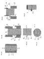
- a rod piece 3 that has a substantially uniform diameter along its length is inserted into a die 1 of a swaging apparatus 6.
- the die 1 includes a through-hole 2 extending vertically and having a diameter slightly greater than that of the rod piece 3, and an concave portion 4 that is formed on the wall surface of the through-hole 2 at a substantially central position in the vertical direction.
- the concave portion 4 assumes an arcuate shape.
- FIG. 1B a sectional view taken along a line A ⁇ A of FIG. 1A, the concave portion 4 assumes a substantially elliptic shape (its radius varies in a sinusoidal manner) whose center is biased from that of the through-hole 2.
- a bulge refers to a portion of a workpiece that has been caused by pressing means or the like to bulge (swell) from the original surface of the workpiece.
- the bulge 5 serves as a salient pole. Since magnetic flux passes along a path of lower reluctance, magnetic flux passes along the top of the bulge 5, which is most distant from the axis of the rotor.
- the bulge 5 is profiled such that the distance to the rotor axis continuously increases in an angular range of 180 degrees as measured around the rotor axis and continuously decreases in the remaining range of 180 degrees as measured around the rotor axis, a change in reluctance can be output in relation to the rotational angle of the rotor.
- reluctance varies with the rotational angle of the rotor in a sinusoidal manner.
- FIG. 2 is a series of configurational views showing Example 2 of swaging for forming a rotor of the present invention having one integrally formed salient pole portion (an example of a plate-shaped bulge).
- FIG. 2A is a sectional view of a swaging apparatus of Example 2, showing a state before application of pressure
- FIG. 2B is a sectional view of the swaging apparatus of Example 2, showing a state after application of pressure
- FIG. 2C shows a completed product.
- a punch 7 has a through-hole 2a into which the rod piece 3 is inserted.
- An insert punch 8 is inserted into the through-hole 2a.
- the die 1 has a through-hole 2b into which the rod piece 3 is inserted.
- a concave portion 10 is formed integral with the through-hole 2b on the end surface of the die 1 located on the side toward the punch 7.
- a knockout pin 9 is inserted into the through-hole 2b.
- the mutually facing end surfaces of the punch 7 and the die 1 are formed flat and come in close contact with each other while the respective through-holes 2a and 2b are aligned.
- the rod piece 3 is inserted into the through-holes 2a and 2b. As shown in FIG. 2A, the insert punch 8 and the knockout pin 9 are brought in contact with the corresponding opposite ends of the rod piece 3.
- the insert punch 8 and the knockout pin 9 are pressed in the directions of arrows P4 and P5, respectively.
- a central portion of the rod piece 3 is extruded into and fills a space defined by the concave portion 10 and the end surface of the punch 7, to thereby be formed into a plate-shaped bulge 11 as shown in FIG. 2B.
- the peripheral edge of the plate-shaped bulge 11 assumes a substantially elliptic shape (its radius varies in a sinusoidal manner) whose center is biased from that of the rod piece 3.
- the die 1 and the punch 7 are separated to thereby remove the resultant rotor having the plate-shaped bulge 11 shown in FIG. 2C.
- a change in reluctance can be output in relation to the rotational angle of the rotor.
- reluctance varies with the rotational angle of the rotor in a sinusoidal manner.
- the above-mentioned swaging process allows formation of a rotor having a salient pole portion in an arbitrary shape in a smaller number of steps.
- Step (1) is similar to the step shown in FIG. 1A.
- a die 13 is configured such that a salient pole-forming concave portion 15 and a positioning projection 16 are formed on a cavity 14.
- the salient pole-forming concave portion 15 is formed to a predetermined depth deeper than the bottom surface of the cavity 14 and extends along the circumferential surface of the rod piece 3 inserted into the die 13.
- the salient pole profile is of a single salient pole (a shaft angle multiplier of 1X).
- the salient pole profile can be formed so as to correspond to any shaft angle multiplier as needed.
- the positioning projection 16 is formed on the bottom surface of the cavity 14 in the proximity of the salient pole-forming concave portion 15 that is located most distant from the axis of the die 13.
- the positioning projection 16 is used to form a positioning portion on a burr 17 that is formed when the bulge 5 is flattened through press-forming. When the burr 17 is to be trimmed off by use of another press die, the positioning portion formed on the burr 17 is used for positioning the intermediate workpiece 20 so as not to accidentally trim off a formed salient pole portion.
- a punch 19 is formed in such a manner as to be insertable into the cavity 14.
- a positioning recess 21 is formed on the end surface of the punch 19 and is loosely engaged with the positioning projection 16.
- the intermediate workpiece 20 having the bulge 5 is set between the die 13 and the punch 19 in such a manner that the bulge 5 is aligned with the salient pole-forming concave portion 15 within the cavity 14.
- FIGS. 3C and 3D which is a sectional view taken along a line A ⁇ A of FIG. 3C
- the innermost circular solid line represents the circumference of the rod piece 3
- the intermediate elliptic dashed line represents the periphery of the plate-shaped bulge 11
- the outermost solid line represents the periphery of the burr 17.
- a cap-like portion 22 is a portion of the burr 17 that is formed by means of the positioning projection 16 of the die 13 and the positioning recess 21 of the punch 19.
- a punching die used in the present finishing step consists of a male die 26 and a female die 27.
- the female die 27 has a punching hole 23 extending therethrough, and a positioning projection 18 is formed on the end surface 28 of the female die 27 in the vicinity of the punch hole 23.
- the male die 26 includes a trunk portion 24 that has a predetermined wall thickness and encircles a rod portion of the set intermediate workpiece 20, and a punch portion 25 that extends from the trunk portion 24 toward the female die 27 along the surface of the rod portion.
- the punch portion 25 is formed in such a manner as to coincide with the shape of the plate-shaped bulge 11, which will become a salient pole portion.
- the intermediate workpiece 20 having the burr 17 of FIG. 3C is set in the female die 27 in such a manner that the cap-like portion 22 of the intermediate workpiece 20 is fitted to the positioning projection 18.
- the punch portion 25 causes the intermediate workpiece 20 having the plate-shaped bulge 11 to drop while the burr 17 is left behind.
- the thus-completed product is a rod piece 3 having the plate-shaped bulge 11, which will serve as a salient pole portion.
- the above-mentioned swaging process allows accurate formation of a rotor having a salient pole portion in an arbitrary shape in a smaller number of steps.
- a concave portion 33 of an upper die 31 and a concave portion 34 of a lower die 32 are formed symmetrically in relation to a horizontal surface 35 of the upper die 31 and a horizontal surface 36 of the lower die 32 as viewed when the upper and lower dies 31 and 32 are closed together.
- the concave portions 33 and 34 are shaped in such a manner as to correspond to upper and lower halves of a rotor 38 that is the rod piece 3 having an integrally formed salient pole portion for a shaft angle multiplier of 1X.
- the rod piece 3 having a cross-sectional area equivalent to that of the rotor 38 is placed in the concave portion 34 of the lower die 32 in an aligned manner.
- the upper die 31 is pressed downward onto the lower die 32 in a closing manner.
- the rotor 38 is formed.
- a burr 37 is created in a clearance between the upper and lower dies 31 and 32. The thickness of the burr 37 is reduced, by pressing the upper die 31 against the lower die 32, to such an extent as not to affect the shape of a salient pole portion at the time of trimming off the burr 37.
- the rotor 38 is placed on a female die 39 in such a manner that the rotor 38 is suspended in a punch hole 41 by means of the burr 37.
- a male die 40 whose width corresponds to the major width of the rotor 38 is pressed downward from above the rotor 38, whereby the body of the rotor 38 drops while the burr 37 is left behind.
- the above-mentioned die-forging process allows formation of a rotor having an arbitrary cross-sectional shape in a smaller number of steps.
- Embodiment 5 shows an example formation of a rotor having two salient pole portions.
- the width of a portion of the rotor as measured at the boundary of two adjacent salient pole portions become smaller than the diameter of a rod portion of the rotor.
- Embodiment 5 is characterized by requiring a step for squeezing a rod piece.
- concave portions 53 and 54 are formed on the wall surface of a through-hole 52.
- the concave portions 53 and 54 are shaped in such a manner as to correspond to the shape of two rounded bulges 55 and 56, which will be described later, formed on the rod piece 3.
- the rod piece 3 is inserted into the through-hole 52 of the die 51.
- Vertical forces are applied to the rod piece 3 in compressing directions P6 and P7 so as to cause vertically intermediate portions of the rod piece 3 to bulge in directions of arrows P8 and P9, thereby symmetrically forming bulges 55 and 56 in such a manner that the bulges 55 and 56 fill the concave portions 53 and 54, respectively.
- a cross section of the rod piece 3 at a portion other than the bulges 55 and 56; i.e., a cross section of the rod piece 3 taken along a line B ⁇ B has a fixed diameter.
- a cross section taken along a line A ⁇ A passing through the respective tops of the bulges 55 and 56 assumes a substantially elliptic shape that bulges out beyond the circumference of the rod piece 3 represented by the dashed line.
- the bulges 55 and 56 are smaller in size than corresponding salient pole portions.
- two bulges 55 and 56 which are prototypes of corresponding salient pole portions (the bulges 55 and 56 are formed into respective salient pole portions in a later step), are axisymmetrically formed adjacent to each other on the rod piece 3.
- FIG. 5D is a sectional view of the rod piece 3 on which the bulges 55 and 56 are formed in the preceding step.
- a double concave portion 60 is formed on a female die 57.
- the double concave portion 60 consists of a concave portion 58 and a concave portion 59, which are provided laterally in a continuous manner.
- a double concave portion 62 is formed on a male die 61.
- the double concave portion 62 consists of a concave portion 63 and a concave portion 64, which are identical to the concave portions 58 and 59 and are provided laterally in a continuous manner.
- the rod piece 3 is placed in the double concave portions 60 in such a manner that one end of a minor diametrical portion of the rod piece 3 rests on a central projection 65 of the double concave portion 60. While positioning is performed in a similar manner, the male die 61 is brought into contact with the rod piece 3 from above. Then, the male die 61 presses the rod piece 3 downward so as to squeeze the rod piece 3 as shown in FIG. 5E.
- FIG. 5F shows the thus-completed product.
- the sectional portion of the rod piece 3 shown in FIG. 5E corresponds to a sectional portion of the completed product taken along a line C ⁇ C of FIG. 5F passing through the respective tops of bulges 67 and 68 of the completed product.
- 5G is a sectional view taken along a line C ⁇ C of FIG. 5F.
- a portion of the contour of the rounded bulges 67 and 68 that extends between the respective tops of the bulges 67 and 68 is formed into the shape of a salient pole profile for a shaft angle multiplier of 2X; i.e., formed such that the aforementioned reluctance varies with the rotational angle of the rotor in a sinusoidal manner.
- the salient pole portions assume the form of the rounded bulges 67 and 68.
- the step of FIG. 3B is additionally performed after the process of FIG. 5.
- the trimming step of FIG. 3E or 4C is additionally performed after the die-forging process.
- the above-mentioned manufacturing method allows formation of a rotor having a salient pole portion in an arbitrary shape in a smaller number of steps.
- a rotary shaft portion and a salient pole portion can be integrally formed into a rotary member from a magnetic material by means of casting or sintering.
- a cast material used to form a rotor must be improved in flexibility so as to avoid the property peculiar to castings of readily fracturing, and must be readily worked.
- malleable cast iron or a ferrite-matrix cast iron that is obtained by heat-treating carbon-added spheroidal graphite cast iron.
- a sprue must not be provided at a position corresponding to a salient pole portion, but must be provided at a position corresponding to a rotary shaft portion.
- a sprue is provided at a position corresponding to a portion of a rotor that does not face a magnetic pole of a stator.
- a sprue is provided at each of positions corresponding to longitudinal opposite end portions of a rotary shaft portion and a central portion of the rotary shaft portion, which do not face a magnetic pole of a stator.
- sintering particularly, iron sintering
- a sintering density of about 7 g/cm 3 is preferred.
- the alloy is formed in such a manner as to predominantly contain iron and to be magnetic and resistant to vibration.
- a process similar to sintering is compacting, in which a magnetic powder material is compacted in a die under high pressure.
- a cutting machine such as a lathe, is used to integrally form a rotary shaft portion and a salient-pole portion by cutting an ingot that is sufficiently large to integrally form the portions.
- the shape of a salient-pole portion is formed by use of a copying apparatus having a master formed to a shape for a required shaft angle multiplier of nX, or by use of a NC machine tool which operates in accordance with a program that represents the manufacturing steps.
- an existing fine machining technique can be used to finely machine a rotary shaft portion and a salient-pole portion.
- a punch having a predetermined shape is caused to abut, at a predetermined angle, the circumferential surface of a rod piece, which will become a rotary shaft portion and is of a magnetic material containing a predominant amount of iron.
- the punch is advanced (or punched).
- a portion of the rod piece in contact with the punch is dented to thereby serve as a deformation portion.
- a portion of the rod piece on which an associated stress acts is caused to bulge, for example, in a direction substantially perpendicular to the abutting direction of the punch.
- the bulge is formed in such a manner that its contour serves as that of a salient pole portion.
- a rotor having a rotary shaft portion, a salient pole portion, and a deformation portion formed integrally.
- the salient pole portion is shaped in such a manner as to correspond to the shape of a salient pole(s) for a shaft angle multiplier of nX (n is an integer of one or greater); i.e., the salient pole portion is shaped such that reluctance in relation to a stator's magnetic pole having output winding varies with the rotational angle of the rotor in a sinusoidal manner. In actuality, reluctance characteristics of a magnetic-pole winding are measured, and the shape of the salient pole portion is modified accordingly.
- the shape of a salient pole portion depends on the shape of a deformation portion.
- the end surface of a magnetic pole of a stator covers a region slightly greater than that covered by a salient pole portion of a rotor and causes a change in reluctance in cooperation with the salient pole portion.
- reluctance can vary with the rotational angle of the rotor in a sinusoidal manner.
- a deformation portion 72 is formed, by means of a punch, on the rod piece 3 along the length of the rod piece 3 in such a manner as to be slightly curved toward a portion of the rod piece 3 that will bulge. As a result, a rounded bulge 71 is formed.
- a cross section of the rod piece 3 taken along a line C ⁇ C which passes through a portion of the rod piece 3 located away from the bulge 71, assumes a circular shape.
- a cross section of the rod piece 3 taken along a line A ⁇ A which passes through the top of the bulge 71, bulges arcuately in contrast to the cross section (in a circular shape) taken along a line C ⁇ C.
- the arcuate shape is formed in such a manner that its contour varies with the rotational angle of the rotor in a sinusoidal manner, whereby the bulge 71 serves as a salient pole portion.
- a cross section of a skirt portion of the bulge 71 i.e., a cross section of the rod piece 3 taken along a line B ⁇ B or a line D ⁇ D, assumes an intermediate shape between the above two cross sections.
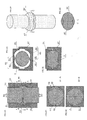
- FIG. 7 is a configurational view showing a VR resolver of the present invention having a rotary shaft portion and a plurality of salient pole portions formed integrally, in which the rotor of the VR resolver is shown in a perspective view, and the stator of the VR resolver is shown in a sectional view.
- An arbitrary number of salient pole portions are formed, by one of the above-described working methods, on a rotary shaft portion 84 in such a manner as to be arranged at predetermined longitudinal intervals.
- three salient pole portions namely, 81, 82, and 83, are provided.
- the salient pole portions 81, 82, and 83 are combined with stator portions 85, 86, 87, 88, 89, and 90, whereby a plurality of resolver units are arranged along the rotational axis of the rotor.
- a resolver unit is a combination of a stator having magnetic poles with windings (excitation winding, sine output winding, and cosine output winding) and a rotor having a rotary shaft portion and a salient pole portion formed integrally.
- Provision of a plurality of resolver units on a single rotary shaft brings the following advantages. For example, in measurement of torsion of a rotary shaft, a conventional method requires attachment of a required number of resolvers to the rotary shaft. However, the present embodiment eliminates such troublesome work. Since a rotary portion and salient pole portions are formed integrally, the structure is simplified, and a single housing can accommodate a plurality of resolver units. Also, positioning is not required for salient pole portions in relation to a rotary shaft portion, thereby facilitating manufacture.
Landscapes
- Physics & Mathematics (AREA)
- General Physics & Mathematics (AREA)
- Manufacture Of Motors, Generators (AREA)
- Transmission And Conversion Of Sensor Element Output (AREA)
- Iron Core Of Rotating Electric Machines (AREA)
Abstract
Description
Claims (9)
- A variable reluctance resolver comprising a rotor having a rotary shaft portion and a salient pole portion integrally formed on the rotary shaft portion.
- A variable reluctance resolver according to claim 1, wherein the salient pole portion assumes a salient pole profile corresponding to a shaft angle multiplier.
- A variable reluctance resolver according to claim 1, wherein two or more salient pole portions are formed on the rotary shaft portion along a length of the rotary shaft portion.
- A variable reluctance resolver according to claim 1, wherein the salient pole portion is a portion of the rotary shaft portion that is caused to bulge and assumes the form of a bulge.
- A variable reluctance resolver according to claim 4, wherein the bulge assumes a plate-like shape.
- A method for manufacturing a variable reluctance resolver recited in claim 1, the method comprising the step of integrally casting the rotary shaft portion and the salient pole portion.
- A method for manufacturing a variable reluctance resolver recited in claim 1, the method comprising the step of integrally sintering the rotary shaft portion and the salient pole portion.
- A method for manufacturing a variable reluctance resolver recited in claim 1, the method comprising the step of forging a rod piece into the rotor having the rotary shaft portion and the salient pole portion formed integrally.
- An apparatus for manufacturing a variable reluctance resolver recited in claim 1 through swaging, comprising a die having a concave portion corresponding to the salient pole portion, the concave portion facing a through-hole formed in the die, and a rod piece being inserted into the through-hole and being subjected to swaging.
Applications Claiming Priority (2)
| Application Number | Priority Date | Filing Date | Title |
|---|---|---|---|
| JP2004027076A JP2005223969A (en) | 2004-02-03 | 2004-02-03 | Variable reluctance resolver, manufacturing method thereof, and manufacturing apparatus |
| JP2004027076 | 2004-02-03 |
Publications (2)
| Publication Number | Publication Date |
|---|---|
| EP1562024A2 true EP1562024A2 (en) | 2005-08-10 |
| EP1562024A3 EP1562024A3 (en) | 2007-04-25 |
Family
ID=34675478
Family Applications (1)
| Application Number | Title | Priority Date | Filing Date |
|---|---|---|---|
| EP04014515A Withdrawn EP1562024A3 (en) | 2004-02-03 | 2004-06-21 | Variable-reluctance resolver and method and apparatus for manufacturing the same |
Country Status (3)
| Country | Link |
|---|---|
| US (1) | US20050168091A1 (en) |
| EP (1) | EP1562024A3 (en) |
| JP (1) | JP2005223969A (en) |
Cited By (1)
| Publication number | Priority date | Publication date | Assignee | Title |
|---|---|---|---|---|
| WO2009015777A1 (en) * | 2007-08-02 | 2009-02-05 | Knorr-Bremse Systeme für Nutzfahrzeuge GmbH | Inductive displacement or rotational angle sensor with a screening plate arranged between two coils |
Families Citing this family (7)
| Publication number | Priority date | Publication date | Assignee | Title |
|---|---|---|---|---|
| JP4085074B2 (en) * | 2004-06-24 | 2008-04-30 | ファナック株式会社 | Method for manufacturing rotating body in magnetic angle detector |
| JP5435580B2 (en) * | 2010-05-27 | 2014-03-05 | 多摩川精機株式会社 | Rotation angle detection or rotation synchronization device |
| WO2014039783A1 (en) | 2012-09-07 | 2014-03-13 | Remy Technologies, Llc | Resolver with mounting structure and method |
| US9520229B2 (en) * | 2014-02-12 | 2016-12-13 | Hamilton Sundstrand Corporation | Rotary transformers for electrical machines |
| DE102014010923A1 (en) * | 2014-07-28 | 2016-01-28 | Micronas Gmbh | Measuring system and drive system |
| CN107968535B (en) * | 2017-12-26 | 2023-10-13 | 浙江联宜电机有限公司 | Auxiliary fixing device for processing inner cavity of rotor |
| WO2023148562A1 (en) * | 2022-02-02 | 2023-08-10 | Nasiri Gheidari Zahra | 2-dof vr resolver for detecting linear and rotational positions in helical motions |
Family Cites Families (18)
| Publication number | Priority date | Publication date | Assignee | Title |
|---|---|---|---|---|
| US2866913A (en) * | 1956-06-27 | 1958-12-30 | Bell Telephone Labor Inc | Multipole pair resolver |
| US3514650A (en) * | 1968-10-02 | 1970-05-26 | Us Army | Variable reluctance synchronal dynamo |
| US3597687A (en) * | 1969-06-20 | 1971-08-03 | Gulf & Western Industries | Apparatus and method for measuring variations in the absorption of energy |
| US3878432A (en) * | 1971-02-16 | 1975-04-15 | Clement A Skalski | Contactless ignition system |
| US3865179A (en) * | 1972-12-15 | 1975-02-11 | Audi Ag | Piston for rotary piston machines and means for its manufacture |
| US3894279A (en) * | 1974-01-04 | 1975-07-08 | Gen Electric | Apparatus for synchronous smoothing of current ripple |
| US4210891A (en) * | 1978-11-20 | 1980-07-01 | Boushey Homer A | Electromagnetic position indicator/differential transformer |
| US4659953A (en) * | 1984-08-21 | 1987-04-21 | Resolvex Corporation | Magnetic structure for synchro and tachometer |
| JPS61102152A (en) * | 1984-10-23 | 1986-05-20 | Shinano Totsuki Kk | Production of rotor and stator for rotary electric machine |
| US5041784A (en) * | 1989-11-16 | 1991-08-20 | Visi-Trak Corporation | Magnetic sensor with rectangular field distorting flux bar |
| US5198763A (en) * | 1990-02-20 | 1993-03-30 | Nikkiso Co., Ltd. | Apparatus for monitoring the axial and radial wear on a bearing of a rotary shaft |
| JP2698013B2 (en) * | 1993-01-19 | 1998-01-19 | 彰 石崎 | Position detection device |
| US5763976A (en) * | 1993-12-15 | 1998-06-09 | Parker-Hannifin Corp. | Stator wound resolver with staggered rotor |
| US5444368A (en) * | 1994-01-10 | 1995-08-22 | H. Magnetic Corp. | Differential reactance permanent magnet position transducer |
| US5469055A (en) * | 1994-05-04 | 1995-11-21 | Honeywell Inc. | Engine shaft with integrally formed complementary targets |
| US5570016A (en) * | 1994-06-01 | 1996-10-29 | General Motors Corporation | Method and apparatus for detecting crankshaft angular position |
| US5739684C1 (en) * | 1996-08-19 | 2002-06-18 | Webb Wheel Products Inc | Unitarily formed hub and abs exciter ring |
| JP3939952B2 (en) * | 2001-10-05 | 2007-07-04 | オークマ株式会社 | Motor with resolver |
-
2004
- 2004-02-03 JP JP2004027076A patent/JP2005223969A/en not_active Withdrawn
- 2004-06-15 US US10/866,801 patent/US20050168091A1/en not_active Abandoned
- 2004-06-21 EP EP04014515A patent/EP1562024A3/en not_active Withdrawn
Cited By (3)
| Publication number | Priority date | Publication date | Assignee | Title |
|---|---|---|---|---|
| WO2009015777A1 (en) * | 2007-08-02 | 2009-02-05 | Knorr-Bremse Systeme für Nutzfahrzeuge GmbH | Inductive displacement or rotational angle sensor with a screening plate arranged between two coils |
| US20100277162A1 (en) * | 2007-08-02 | 2010-11-04 | Thomas Feucht | Inductive displacement or rotational angle sensor with a screening plate arranged between two coils |
| US8334689B2 (en) | 2007-08-02 | 2012-12-18 | Knorr-Bremse Systeme Fuer Nutzfahrzeuge Gmbh | Inductive displacement or rotational angle sensor with a screening plate arranged between two coils |
Also Published As
| Publication number | Publication date |
|---|---|
| JP2005223969A (en) | 2005-08-18 |
| EP1562024A3 (en) | 2007-04-25 |
| US20050168091A1 (en) | 2005-08-04 |
Similar Documents
| Publication | Publication Date | Title |
|---|---|---|
| US8181333B2 (en) | Method of manufacturing squirrel-cage rotor | |
| CN102082470B (en) | Laminated stator core | |
| TWI637583B (en) | Axial gap rotary electric machine | |
| JP2010252560A (en) | Method for forming Randel type iron core for rotating electrical machine and a pair of Randel type iron core | |
| WO2010131672A1 (en) | Substantially cylindrical powder compact and powder die device | |
| CN114207992B (en) | Iron core sheet, stator iron core, stator and rotating electrical machine | |
| CN111069362A (en) | Forming method of tubular part | |
| US20050168091A1 (en) | Variable reluctance resolver and method and apparatus for manufacturing same | |
| JP3606566B2 (en) | Method for manufacturing rotor core for permanent magnet alternator | |
| JPWO2017195249A1 (en) | Stator iron core and motor having the stator iron core | |
| CN111095750A (en) | Method for manufacturing iron core for rotating electrical machine | |
| JPS62100150A (en) | Manufacturing method for rotor core of alternating current generator | |
| JP2008301568A (en) | Cage rotor, induction motor, and method of manufacturing cage rotor | |
| JP2008289309A (en) | Linked laminated core, armature manufacturing method, and progressive mold apparatus | |
| JP2003219613A (en) | Manufacturing method of amorphous laminated core | |
| JP4794650B2 (en) | Rotating electric machine | |
| JP3609745B2 (en) | Method for manufacturing rotor core for permanent magnet alternator | |
| JP4887178B2 (en) | Mold for molding | |
| JP3842146B2 (en) | Manufacturing method of laminated iron core | |
| WO2019002142A1 (en) | Forging method, rotor shaft and electric motor | |
| EP3727717A1 (en) | Method for manufacturing a lamina for a laminated core for an electric machine | |
| JP4989877B2 (en) | Manufacturing method of rotor laminated core | |
| CN115301833B (en) | Method for producing a sheet metal part | |
| JP3544117B2 (en) | Manufacturing method of laminated iron core | |
| JP2022029750A (en) | Manufacturing method of rotor shaft |
Legal Events
| Date | Code | Title | Description |
|---|---|---|---|
| PUAI | Public reference made under article 153(3) epc to a published international application that has entered the european phase |
Free format text: ORIGINAL CODE: 0009012 |
|
| AK | Designated contracting states |
Kind code of ref document: A2 Designated state(s): AT BE BG CH CY CZ DE DK EE ES FI FR GB GR HU IE IT LI LU MC NL PL PT RO SE SI SK TR |
|
| AX | Request for extension of the european patent |
Extension state: AL HR LT LV MK |
|
| PUAL | Search report despatched |
Free format text: ORIGINAL CODE: 0009013 |
|
| AK | Designated contracting states |
Kind code of ref document: A3 Designated state(s): AT BE BG CH CY CZ DE DK EE ES FI FR GB GR HU IE IT LI LU MC NL PL PT RO SE SI SK TR |
|
| AX | Request for extension of the european patent |
Extension state: AL HR LT LV MK |
|
| 17P | Request for examination filed |
Effective date: 20070706 |
|
| AKX | Designation fees paid |
Designated state(s): DE FR GB IT |
|
| STAA | Information on the status of an ep patent application or granted ep patent |
Free format text: STATUS: THE APPLICATION HAS BEEN WITHDRAWN |
|
| 18W | Application withdrawn |
Effective date: 20080130 |