EP1561917B1 - Dynamic exhaust system for advanced internal combustion engines - Google Patents
Dynamic exhaust system for advanced internal combustion engines Download PDFInfo
- Publication number
- EP1561917B1 EP1561917B1 EP05000646A EP05000646A EP1561917B1 EP 1561917 B1 EP1561917 B1 EP 1561917B1 EP 05000646 A EP05000646 A EP 05000646A EP 05000646 A EP05000646 A EP 05000646A EP 1561917 B1 EP1561917 B1 EP 1561917B1
- Authority
- EP
- European Patent Office
- Prior art keywords
- valve
- resonator
- exhaust
- gas flow
- exhaust gas
- Prior art date
- Legal status (The legal status is an assumption and is not a legal conclusion. Google has not performed a legal analysis and makes no representation as to the accuracy of the status listed.)
- Expired - Lifetime
Links
Images

Classifications
-
- F—MECHANICAL ENGINEERING; LIGHTING; HEATING; WEAPONS; BLASTING
- F01—MACHINES OR ENGINES IN GENERAL; ENGINE PLANTS IN GENERAL; STEAM ENGINES
- F01N—GAS-FLOW SILENCERS OR EXHAUST APPARATUS FOR MACHINES OR ENGINES IN GENERAL; GAS-FLOW SILENCERS OR EXHAUST APPARATUS FOR INTERNAL-COMBUSTION ENGINES
- F01N13/00—Exhaust or silencing apparatus characterised by constructional features
- F01N13/02—Exhaust or silencing apparatus characterised by constructional features having two or more separate silencers in series
-
- F—MECHANICAL ENGINEERING; LIGHTING; HEATING; WEAPONS; BLASTING
- F01—MACHINES OR ENGINES IN GENERAL; ENGINE PLANTS IN GENERAL; STEAM ENGINES
- F01N—GAS-FLOW SILENCERS OR EXHAUST APPARATUS FOR MACHINES OR ENGINES IN GENERAL; GAS-FLOW SILENCERS OR EXHAUST APPARATUS FOR INTERNAL-COMBUSTION ENGINES
- F01N1/00—Silencing apparatus characterised by method of silencing
- F01N1/16—Silencing apparatus characterised by method of silencing by using movable parts
- F01N1/161—Silencing apparatus characterised by method of silencing by using movable parts for adjusting resonance or dead chambers or passages to resonance or dead chambers
- F01N1/163—Silencing apparatus characterised by method of silencing by using movable parts for adjusting resonance or dead chambers or passages to resonance or dead chambers by means of valves
-
- F—MECHANICAL ENGINEERING; LIGHTING; HEATING; WEAPONS; BLASTING
- F01—MACHINES OR ENGINES IN GENERAL; ENGINE PLANTS IN GENERAL; STEAM ENGINES
- F01N—GAS-FLOW SILENCERS OR EXHAUST APPARATUS FOR MACHINES OR ENGINES IN GENERAL; GAS-FLOW SILENCERS OR EXHAUST APPARATUS FOR INTERNAL-COMBUSTION ENGINES
- F01N1/00—Silencing apparatus characterised by method of silencing
- F01N1/16—Silencing apparatus characterised by method of silencing by using movable parts
- F01N1/166—Silencing apparatus characterised by method of silencing by using movable parts for changing the flow path through the silencer or for adjusting the dimensions of a chamber or a pipe
-
- F—MECHANICAL ENGINEERING; LIGHTING; HEATING; WEAPONS; BLASTING
- F01—MACHINES OR ENGINES IN GENERAL; ENGINE PLANTS IN GENERAL; STEAM ENGINES
- F01N—GAS-FLOW SILENCERS OR EXHAUST APPARATUS FOR MACHINES OR ENGINES IN GENERAL; GAS-FLOW SILENCERS OR EXHAUST APPARATUS FOR INTERNAL-COMBUSTION ENGINES
- F01N13/00—Exhaust or silencing apparatus characterised by constructional features
- F01N13/011—Exhaust or silencing apparatus characterised by constructional features having two or more purifying devices arranged in parallel
-
- F—MECHANICAL ENGINEERING; LIGHTING; HEATING; WEAPONS; BLASTING
- F01—MACHINES OR ENGINES IN GENERAL; ENGINE PLANTS IN GENERAL; STEAM ENGINES
- F01N—GAS-FLOW SILENCERS OR EXHAUST APPARATUS FOR MACHINES OR ENGINES IN GENERAL; GAS-FLOW SILENCERS OR EXHAUST APPARATUS FOR INTERNAL-COMBUSTION ENGINES
- F01N2390/00—Arrangements for controlling or regulating exhaust apparatus
- F01N2390/08—Arrangements for controlling or regulating exhaust apparatus using mechanical components only, e.g. actuated manually
-
- F—MECHANICAL ENGINEERING; LIGHTING; HEATING; WEAPONS; BLASTING
- F01—MACHINES OR ENGINES IN GENERAL; ENGINE PLANTS IN GENERAL; STEAM ENGINES
- F01N—GAS-FLOW SILENCERS OR EXHAUST APPARATUS FOR MACHINES OR ENGINES IN GENERAL; GAS-FLOW SILENCERS OR EXHAUST APPARATUS FOR INTERNAL-COMBUSTION ENGINES
- F01N2430/00—Influencing exhaust purification, e.g. starting of catalytic reaction, filter regeneration, or the like, by controlling engine operating characteristics
- F01N2430/02—Influencing exhaust purification, e.g. starting of catalytic reaction, filter regeneration, or the like, by controlling engine operating characteristics by cutting out a part of engine cylinders
Definitions
- the invention relates generally to sound, performance and emission control in vehicles utilizing advanced technology, such as cylinder deactivation or hybrid power sources wherein discontinuations occur in the exhaust gas flow rate during operation of the engine.
- Advanced internal combustion engine systems include non-conventional internal combustion power plants, such as cylinder deactivation engines, and are more difficult to acoustically attenuate in the exhaust system, because they have a broader range of noise frequencies and a broader range of gas flow (volume per unit time) to deal with.
- the use of a muffler valve to achieve greater acoustic attenuation is known, especially with conventional engine systems. Passive valves are traditionally used only on conventional engines at lower temperature locations in the exhaust system downstream of the engine.
- active or semi-active valves to handle variable exhaust flow requirements and to simultaneously withstand increased heat requirements of such advanced engine systems.
- active or semi-active valves involve not only expensive hardware and accessory power systems to actuate such valves, but additionally are associated with expensive control modules with accompanying software control for vehicles incorporating such advanced engine techniques.
- active or semi-active valve systems have recently been used due to the inability of previous passive muffler valve arrangements to withstand the heat requirements in areas along a longitudinal length of the exhaust system where the use of such valves is most optimally applied to noise abatement, performance improvement and/or emission reduction.
- JP 2000 257418 JP 57 076 220 , US 6 173 808 , and US 2003/145584 .
- Passive valves have traditionally been used to create dynamic exhaust systems in conventional engines. However, these systems have a continuous response proportional to engine speed, a continuous increase in exhaust system pressure as a function of engine speed, and do not have to deal with conditions that are not continuous with engine speed but rather involve step functions of exhaust flow during operation of the vehicle's power source. Many advanced engine designs, such as cylinder deactivation systems, create unique exhaust conditions that are not continuous with engine speed or possess larger than normal ranges in exhaust flow wherein cost effective management of sound and/or emissions cannot be met by conventional exhaust system designs.
- a “passive valve” is one in which the motive force to operate the valve comes from the energy (velocity or pressure) in exhaust gas flow.
- the motive energy comes from the velocity of the gas hitting a component of the valve, such as a head or flapper or other element placed in the exhaust stream.
- the valve is moved by forces exerted from a pressure difference between an upstream and a downstream location on either side of the valve element.
- the valve is controlled and moved by conditions on either side of the valve element which has been placed in the exhaust stream.
- a "semi-active valve” in addition to utilizing the motive forces for operation used by a passive valve, additionally utilizes motive force that does not burden the gas flow. This additional motive force is derived from an external pressure differential between the interior of the exhaust system and atmospheric pressure.
- An “active valve” is powered or controlled at least in part by a source other than the exhaust pressure or gas velocity.
- a vehicle engine controller may send an electrical signal to a solenoid-operated valve whenever appropriate conditions so dictate.
- the solenoid controls a vacuum to an actuator for the valve which is appropriately positioned in the exhaust stream.
- Figure 1 is a top perspective view of an exhaust system for an advanced internal combustion engine arranged in accordance with the principles of the invention.
- Figure 2 sets forth region 2 of Fig. 1 in more detail.
- the invention utilizes the application of a low cost passive valve which can withstand high temperatures allowing the design freedom to locate the valve in the exhaust system at a position where optimum sound attenuation results.
- This passive, temperature resistant valve is specifically applied to advanced non-conventional power sources which are more challenging to acoustic attenuation.
- Advanced internal combustion power sources for vehicles significantly change their gas flow characteristics during operation.
- advanced non-conventional engine technologies include cylinder deactivation systems, hybrid systems including gas/electric, hydrogen or other types of hybrid source powered vehicles.
- Use of the passive, temperature resistant valve in such exhaust systems restricts, reflects, and/or routes the exhaust gas stream for the purposes of improving emissions, performance or sound control, or combinations thereof.
- FIG. 1 One example of the use of a passive, temperature resistive valve to control sound in an exhaust system of a cylinder deactivation engine-type vehicle is set forth in the perspective view of Fig. 1 .
- System 100 includes manifold exhaust conduits 102 and 104, respectively, for first and second cylinder banks of the engine (not shown).
- catalytic converters 106 and 108 Situated in conduits 102 and 104 are catalytic converters 106 and 108, respectively, which are, in turn, coupled via exhaust conduits 110 and 112 to a flexible joint and collector element 114.
- Flexible joint 114 is coupled to an input of a resonator or mini-muffler 116. Interior to resonator 116 is at least a first conduit which has an outlet at least partially restricted via a passive, temperature resistant valve element 118. An outlet of resonator 116 is coupled to an intermediate exhaust conduit 120 which passes the exhaust stream to a muffler 122. An output of muffler 122 is, in turn, coupled to an exhaust system tailpipe 124. "L" represents a longitudinal length of exhaust system 100.
- the positioning of the restricting valve 118 is optimally placed approximately in the midpoint along axial distance L, or between the midpoint and the engine, or at least nearer to the midpoint, or U2 than to either endpoint of the exhaust system apparatus.
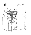
- FIG. 2 details of a passive temperature resistive valve suitable for use with the invention and its location with respect to a resonator 116 of Fig. 1 are set forth.
- An end 220 of an exhaust conduit 222 extending into the resonator 116 from an inlet thereof is conically widened or flanged at end 220.
- a peripheral edge of conical valve disk 218 is conically flared to the purpose of the curved or flared interface is to promote good gas flow characteristics.
- Valve disk 218 lies adjacent end 220 of conduit 222.
- an unflared or straight-edged conduit and mating disk 218 may be employed.
- valve surface 218 is shown substantially closing off an outlet of conduit 222, it has been found optimum, in the rest position of valve 118 to maintain an opening annular gap between end 220 of conduit 222 and valve disk 218 of on the order of one to two millimeters for optimum noise attenuation.
- Valve disk 218 is mounted on a guide rod 216, guided in turn in a guide sleeve 214.
- Guide sleeve 214 is held by an assembly sleeve 212 mounted in a gastight fashion to the wall of the housing of resonator 116.
- a valve housing 208 holds a conical spring 204 which is retained by a spring suspension member 202.
- the other end of spring 204 bears upon a spring guide disk 206 mounted at the end of the guide rod 216. In this way, spring 204 has a secure support and distributes its force symmetrically and axially to guide rod 216.
- a ring 210 of wire net is placed on guide rod 216 to serve as a damping element to abate noise interference which could otherwise be caused by vibrations of valve disk 218.
- Valve 118 as set forth in Fig. 2 is "temperature resistant", in that its spring biasing component is housed exteriorly of the actual flow path of exhaust gases in the systems. Additionally, valve 118 contains no membrane elements conventionally required in active and semi-active valve components which are more susceptible to degradation under high temperature.
- the invention enables the restriction, reflection or rerouting of exhaust gases in power plants which significantly change their gas flow characteristics during operation for the purposes of improving emissions or control of sound in the exhaust system.
- the passive valve appropriately positioned within the exhaust system offers high temperature, e.g., above 700°C, resistance for periods of time which is required in many advanced internal combustion systems.
Landscapes
- Engineering & Computer Science (AREA)
- Chemical & Material Sciences (AREA)
- Combustion & Propulsion (AREA)
- Mechanical Engineering (AREA)
- General Engineering & Computer Science (AREA)
- Exhaust Silencers (AREA)
Description
- The invention relates generally to sound, performance and emission control in vehicles utilizing advanced technology, such as cylinder deactivation or hybrid power sources wherein discontinuations occur in the exhaust gas flow rate during operation of the engine.
- Conventional internal combustion engines or power sources continuously use all cylinders during operation. Advanced internal combustion engine systems include non-conventional internal combustion power plants, such as cylinder deactivation engines, and are more difficult to acoustically attenuate in the exhaust system, because they have a broader range of noise frequencies and a broader range of gas flow (volume per unit time) to deal with. The use of a muffler valve to achieve greater acoustic attenuation is known, especially with conventional engine systems. Passive valves are traditionally used only on conventional engines at lower temperature locations in the exhaust system downstream of the engine. Recently, expensive systems to achieve noise attenuation in advanced non-conventional engine vehicles have utilized active or semi-active valves to handle variable exhaust flow requirements and to simultaneously withstand increased heat requirements of such advanced engine systems. Such active or semi-active valves, however, involve not only expensive hardware and accessory power systems to actuate such valves, but additionally are associated with expensive control modules with accompanying software control for vehicles incorporating such advanced engine techniques. These more expensive active or semi-active valve systems have recently been used due to the inability of previous passive muffler valve arrangements to withstand the heat requirements in areas along a longitudinal length of the exhaust system where the use of such valves is most optimally applied to noise abatement, performance improvement and/or emission reduction.
- Different types of mufflers may be seen in:
JP 2000 257418 JP 57 076 220 US 6 173 808 , andUS 2003/145584 . - Passive valves have traditionally been used to create dynamic exhaust systems in conventional engines. However, these systems have a continuous response proportional to engine speed, a continuous increase in exhaust system pressure as a function of engine speed, and do not have to deal with conditions that are not continuous with engine speed but rather involve step functions of exhaust flow during operation of the vehicle's power source. Many advanced engine designs, such as cylinder deactivation systems, create unique exhaust conditions that are not continuous with engine speed or possess larger than normal ranges in exhaust flow wherein cost effective management of sound and/or emissions cannot be met by conventional exhaust system designs.
- For the purposes of this disclosure, a "passive valve" is one in which the motive force to operate the valve comes from the energy (velocity or pressure) in exhaust gas flow. For the case of a gas velocity powered valve, the motive energy comes from the velocity of the gas hitting a component of the valve, such as a head or flapper or other element placed in the exhaust stream. For the case of pressure, the valve is moved by forces exerted from a pressure difference between an upstream and a downstream location on either side of the valve element. In summary, the valve is controlled and moved by conditions on either side of the valve element which has been placed in the exhaust stream.
- A "semi-active valve" in addition to utilizing the motive forces for operation used by a passive valve, additionally utilizes motive force that does not burden the gas flow. This additional motive force is derived from an external pressure differential between the interior of the exhaust system and atmospheric pressure.
- An "active valve" is powered or controlled at least in part by a source other than the exhaust pressure or gas velocity. For example, a vehicle engine controller may send an electrical signal to a solenoid-operated valve whenever appropriate conditions so dictate. The solenoid, in turn, controls a vacuum to an actuator for the valve which is appropriately positioned in the exhaust stream.
- In accordance with the need demonstrated by the prior art, a method of controlling exhaust flow in accordance with claim 1.
- In another aspect of the invention, an arrangement for controlling exhaust flow in accordance with claim 9.
- The objects and features of the invention will become apparent from a reading of a detailed description, taken in conjunction with the drawing, in which:
-
Figure 1 is a top perspective view of an exhaust system for an advanced internal combustion engine arranged in accordance with the principles of the invention; and -
Figure 2 sets forth region 2 ofFig. 1 in more detail. - The invention utilizes the application of a low cost passive valve which can withstand high temperatures allowing the design freedom to locate the valve in the exhaust system at a position where optimum sound attenuation results. This passive, temperature resistant valve is specifically applied to advanced non-conventional power sources which are more challenging to acoustic attenuation.
- Advanced internal combustion power sources for vehicles significantly change their gas flow characteristics during operation. Examples of such advanced non-conventional engine technologies include cylinder deactivation systems, hybrid systems including gas/electric, hydrogen or other types of hybrid source powered vehicles. Use of the passive, temperature resistant valve in such exhaust systems restricts, reflects, and/or routes the exhaust gas stream for the purposes of improving emissions, performance or sound control, or combinations thereof.
- It has been determined by experience that the most effective location for such a passive, temperature resistant valve in the exhaust stream of an advanced internal combustion engine powered vehicle is approximately at the longitudinal midpoint of the exhaust gas flow. It is believed that positioning of the valve at this location most effectively disturbs or breaks up low frequency, long length sound waves being propagated along the exhaust path. This is especially true in cylinder deactivation-type power plants where a portion of the internal combustion cylinders are deactivated under appropriate operating conditions, thereby generating a discontinuity in the gas flow of the exhaust. Other placements of the valve produce acceptable results when the valve is between an engine end of the exhaust system and a longitudinal midpoint thereof. Additionally, it may be acceptable to place the valve closer to the midpoint than to either end of the exhaust system.
- It has additionally been determined that the most effective acoustic attenuation in such exhaust systems is obtained by placing a barrier surface in the gas stream having an approximately perpendicular surface with respect to an axial flow direction of the exhaust stream. Such a transverse barrier surface is believed to set up more effective reflections in the sound waves associated with the exhaust to provide better noise cancellation.
- One example of the use of a passive, temperature resistive valve to control sound in an exhaust system of a cylinder deactivation engine-type vehicle is set forth in the perspective view of
Fig. 1 . With reference toFig. 1 , anexhaust system 100 for a cylinder deactivation engine system, such as a V-8 internal combustion engine having the capability of deactivating up to four of the eight cylinders at a time is set forth.System 100 includesmanifold exhaust conduits conduits catalytic converters 106 and 108, respectively, which are, in turn, coupled viaexhaust conduits collector element 114. -
Flexible joint 114 is coupled to an input of a resonator or mini-muffler 116. Interior toresonator 116 is at least a first conduit which has an outlet at least partially restricted via a passive, temperatureresistant valve element 118. An outlet ofresonator 116 is coupled to anintermediate exhaust conduit 120 which passes the exhaust stream to amuffler 122. An output ofmuffler 122 is, in turn, coupled to anexhaust system tailpipe 124. "L" represents a longitudinal length ofexhaust system 100. As mentioned previously, it has been found that the positioning of the restrictingvalve 118 is optimally placed approximately in the midpoint along axial distance L, or between the midpoint and the engine, or at least nearer to the midpoint, or U2 than to either endpoint of the exhaust system apparatus. - With reference to
Fig. 2 , details of a passive temperature resistive valve suitable for use with the invention and its location with respect to aresonator 116 ofFig. 1 are set forth. Anend 220 of anexhaust conduit 222 extending into theresonator 116 from an inlet thereof is conically widened or flanged atend 220. Similarly, a peripheral edge ofconical valve disk 218 is conically flared to the purpose of the curved or flared interface is to promote good gas flow characteristics. Valvedisk 218 liesadjacent end 220 ofconduit 222. Alternatively, an unflared or straight-edged conduit andmating disk 218 may be employed. Whilevalve surface 218 is shown substantially closing off an outlet ofconduit 222, it has been found optimum, in the rest position ofvalve 118 to maintain an opening annular gap betweenend 220 ofconduit 222 andvalve disk 218 of on the order of one to two millimeters for optimum noise attenuation. - Valve
disk 218 is mounted on aguide rod 216, guided in turn in aguide sleeve 214.Guide sleeve 214 is held by anassembly sleeve 212 mounted in a gastight fashion to the wall of the housing ofresonator 116. External to theresonator 116, avalve housing 208 holds aconical spring 204 which is retained by aspring suspension member 202. The other end ofspring 204 bears upon aspring guide disk 206 mounted at the end of theguide rod 216. In this way,spring 204 has a secure support and distributes its force symmetrically and axially to guiderod 216. - Between the
spring guide disk 206 and thevalve housing 208, aring 210 of wire net is placed onguide rod 216 to serve as a damping element to abate noise interference which could otherwise be caused by vibrations ofvalve disk 218. - When the quantity of exhaust gas flowing through
conduit 222 into the housing ofresonator 116 increases sufficiently--e.g., by activating all eight cylinders of the engine coupled toexhaust system 100, the impact onvalve disk 218 is sufficient to forceelement 218 away fromend 220 ofconduit 222 against the force ofspring 204 to substantially remove restriction of exhaust gas flow. When the exhaust gas flow discontinuously decreases during engine operation, for example, by deactivating four of the eight cylinders of the engine, the force ofspring 204 overcomes the exhaust flow force exerted onmember 218, allowing it to travel to the left as shown inFig. 2 to substantially restrict the exhaust flow which sets up reflections of the sound waves accompanying the exhaust flow which tend to be of long length and low frequency under such engine operating conditions. This restriction/reflection effect thereby attenuates sound under the four cylinder engine operating condition without the need to resort to unacceptably large muffler volumes that would otherwise be required. - Other examples of the use of a passive, temperature resistant valve as described above, would include rerouting of exhaust gases under appropriate gas flow conditions to make more effective and dynamic use of conventional muffler systems or emission control systems.
-
Valve 118 as set forth inFig. 2 , is "temperature resistant", in that its spring biasing component is housed exteriorly of the actual flow path of exhaust gases in the systems. Additionally,valve 118 contains no membrane elements conventionally required in active and semi-active valve components which are more susceptible to degradation under high temperature. - Finally, from
Fig. 2 , it will be seen that exhaust gas flow, whether restricted under low flow conditions or unrestricted under high flow conditions continues its path out ofconduit 222 into the interior ofresonator 116 and then through outlet opening 226 ofresonator 116 intointermediate exhaust conduit 120. - Hence, the invention enables the restriction, reflection or rerouting of exhaust gases in power plants which significantly change their gas flow characteristics during operation for the purposes of improving emissions or control of sound in the exhaust system. Additionally, the passive valve, appropriately positioned within the exhaust system offers high temperature, e.g., above 700°C, resistance for periods of time which is required in many advanced internal combustion systems.
Claims (16)
- A method of controlling exhaust flow in an exhaust system for an internal combustion power source of a vehicle equipped with a cylinder deactivation system exhibiting, during operation, discontinuities in exhaust gas flow, the method comprising:1. a passive temperature resistant valve is placed in a resonator (116) in a path of exhaust gas flow from the internal combustion power source, and2. the valve at least partially alters a characteristic of the exhaust gas flow whenever a discontinuity in exhaust gas occurs,
characterized in that
step 1. comprises placing the valve in the resonator (116), the resonator comprising an exhaust conduit (222) extending therein and having an end (220), and that the valve comprises:- a valve disk (218) positioned adjacent to the end (220), the valve disk being mounted on a guide rod (216), a spring guide disc (206) being mounted at the opposite end of the guide rod (216),- a guide sleeve mounted in a gastight fashion to a housing of the resonator (116), the guide sleeve guiding the guide rod (216),- a valve housing (208) positioned externally to the resonator (116), and- a spring biasing component (204) positioned in the valve housing (208) between the spring guide disk (206) and the valve housing (208), andthat step 2. comprises the valve acting on the gas flow in the resonator (116) due to the spring biasing component (204) acting on the gas flow via the valve disk (218). - The method of claim 1 wherein the step of altering the characteristic of the exhaust gas flow comprises altering at least one of flow restriction, flow reflection and flow direction.
- The method of claim 1 or 2 wherein the placing step comprises placing the passive, temperature resistant valve nearer to a midpoint of the exhaust system than to an endpoint thereof.
- The method of any of claims 1-3 wherein the placing step comprises placing the passive, temperature resistant valve substantially at a midpoint of the exhaust system.
- The method of claim 1 or 2 wherein the placing step comprises placing the passive, temperature resistant valve between a midpoint of the exhaust system and the non-conventional power source.
- The method of claim 1 wherein the altering step comprises the passive, temperature resistant valve increasing restriction of exhaust gas flow whenever a discontinuous decrease in exhaust gas flow rate occurs.
- The method of claim 6 wherein the altering step comprises the passive, temperature resistant valve restricting exhaust gas flow via a valve surface extending substantially perpendicular to a longitudinal axis of exhaust flow.
- The method of claim 7 wherein the placing step comprises positioning a valve surface in a resonator having an inlet coupled to an interior conduit extending into the resonator and terminating in the resonator adjacent to the valve surface.
- An arrangement for controlling exhaust flow in an exhaust system for an internal combustion power source of a vehicle equipped with a cylinder deactivation system exhibiting, during operation, discontinuities in exhaust gas flow, the arrangement having a resonator (116) in a path of exhaust gas flow and a passive, temperature resistant valve being positioned In the resonator (116), the valve operative to at least partially alter a characteristic of the exhaust gas flow whenever a discontinuity in exhaust gas flow occurs, characterized in that:- the resonator (116) comprises an exhaust conduit (222) extending therein and having an end (220),- the valve comprises:- a valve disk (218) positioned adjacent to the end (220), the valve disk being mounted on a guide rod (216), a spring guide disc (206) being mounted at the opposite end of the guide rod (216),- a guide sleeve mounted in a gastight fashion to a housing of the resonator (116), the guide sleeve guiding the guide rod (216),- a valve housing (208) positioned externally to the resonator (116),- a spring biasing component (204) positioned in the valve housing (208), between the spring guide disk (206) and the valve housing (208).
- The arrangement of claim 9 wherein the characteristic of the exhaust gas flow comprises at least one of flow restriction, flow reflection and flow direction.
- The arrangement of claim 9 wherein the passive, temperature resistant valve is placed nearer to a midpoint of the exhaust system than to an endpoint thereof.
- The arrangement of any of claims 9-10 wherein the passive, temperature resistant valve is placed substantially at a midpoint of the exhaust system.
- The arrangement of any of claims 9-10 wherein the passive, temperature resistant valve is placed between a midpoint of the exhaust system and the internal combustion power source.
- The arrangement of claim 9 wherein the passive, temperature resistant valve is adapted to Increase restriction of exhaust gas flow whenever a discontinuous predetermined decrease in exhaust gas flow rate occurs.
- The arrangement of claim 14 wherein the passive, temperature resistant valve is adapted to restrict exhaust gas flow via a valve surface extending substantially perpendicular to a longitudinal axis of exhaust flow.
- The arrangement of claim 15 wherein the valve surface is positioned in a resonator having an inlet coupled to an interior conduit extending into the resonator and terminating in the resonator adjacent to the valve surface.
Applications Claiming Priority (2)
| Application Number | Priority Date | Filing Date | Title |
|---|---|---|---|
| US760179 | 2004-01-16 | ||
| US10/760,179 US20050155816A1 (en) | 2004-01-16 | 2004-01-16 | Dynamic exhaust system for advanced internal combustion engines |
Publications (2)
| Publication Number | Publication Date |
|---|---|
| EP1561917A1 EP1561917A1 (en) | 2005-08-10 |
| EP1561917B1 true EP1561917B1 (en) | 2008-06-04 |
Family
ID=34679321
Family Applications (1)
| Application Number | Title | Priority Date | Filing Date |
|---|---|---|---|
| EP05000646A Expired - Lifetime EP1561917B1 (en) | 2004-01-16 | 2005-01-14 | Dynamic exhaust system for advanced internal combustion engines |
Country Status (3)
| Country | Link |
|---|---|
| US (1) | US20050155816A1 (en) |
| EP (1) | EP1561917B1 (en) |
| DE (1) | DE602005007277D1 (en) |
Families Citing this family (14)
| Publication number | Priority date | Publication date | Assignee | Title |
|---|---|---|---|---|
| DE10319212B4 (en) * | 2003-04-29 | 2010-02-11 | Heinrich Gillet Gmbh | Silencer with variable acoustic properties |
| US7673720B2 (en) * | 2006-03-02 | 2010-03-09 | Pacbrake Company | High-performance muffler assembly with multiple modes of operation |
| WO2009067430A2 (en) * | 2007-11-21 | 2009-05-28 | Emcon Technologies Llc | Exhaust valve assembly |
| US7628250B2 (en) * | 2007-11-21 | 2009-12-08 | Emcon Technologies Llc | Passive valve assembly for vehicle exhaust system |
| DE112010000933T5 (en) * | 2009-02-26 | 2012-11-08 | Faurecia Emissions Control Technologies, Usa Llc | Temperature and flow control of exhaust gas for thermoelectric units |
| JP5389477B2 (en) * | 2009-03-05 | 2014-01-15 | 株式会社Roki | Intake sound adjustment device |
| AT507516B1 (en) | 2010-02-04 | 2011-07-15 | Avl List Gmbh | INTERNAL COMBUSTION ENGINE WITH CYLINDER SHUT OFF |
| KR20140077039A (en) * | 2012-12-13 | 2014-06-23 | 현대자동차주식회사 | Variable valve appratus and muffler provided with the same |
| KR101517790B1 (en) * | 2013-10-15 | 2015-05-06 | 현대자동차주식회사 | Muffler of exhaust system for cda engine |
| KR101517792B1 (en) * | 2013-10-15 | 2015-05-06 | 현대자동차주식회사 | Muffler of exhaust system for cda engine |
| US9695719B2 (en) * | 2014-09-24 | 2017-07-04 | Kawasaki Jukogyo Kabushiki Kaisha | Exhaust muffler device for combustion engine |
| KR101867573B1 (en) * | 2016-05-23 | 2018-06-15 | 현대자동차주식회사 | Slip-type active noise control muffler and method for controlling the same |
| US11149602B2 (en) | 2018-05-22 | 2021-10-19 | Faurecia Emissions Control Technologies, Usa, Llc | Passive flap valve for vehicle exhaust system |
| US11401851B1 (en) * | 2019-06-18 | 2022-08-02 | Tilahun Anshu | Vehicular exhaust system |
Family Cites Families (34)
| Publication number | Priority date | Publication date | Assignee | Title |
|---|---|---|---|---|
| US1403614A (en) * | 1920-10-11 | 1922-01-17 | August W Ruehl | Muffler |
| US2625234A (en) * | 1950-05-10 | 1953-01-13 | Perry B Fina | Valve controlled muffler with a plurality of through passages |
| FR87613E (en) * | 1964-11-05 | 1966-04-15 | Berliet Automobiles | Device for cleaning the exhaust gases of heat engines containing solid components |
| US3620330A (en) * | 1969-04-14 | 1971-11-16 | Oldberg Mfg Co | Muffler construction and method of selectively modifying its sound-attenuating characteristics |
| JPS5776220A (en) * | 1980-10-29 | 1982-05-13 | Nippon Radiator Co Ltd | Muffler |
| FR2514412A1 (en) * | 1981-10-14 | 1983-04-15 | Peugeot Cycles | DEVICE FOR MODULATING THE FLOW OF GASES IN AN EXHAUST MUFFLER OF AN INTERNAL COMBUSTION ENGINE |
| CH662895A5 (en) * | 1983-09-27 | 1987-10-30 | Fischer Ag Georg | METHOD AND DEVICE FOR REGULATING A SIZE. |
| JPS61162001A (en) * | 1985-01-11 | 1986-07-22 | Toray Ind Inc | Optical lens having antireflection film |
| US4913260A (en) * | 1988-01-11 | 1990-04-03 | Tenneco Inc. | Gas silencing system with controlling sound attenuation |
| US5246205A (en) * | 1992-04-06 | 1993-09-21 | Donaldson Company, Inc. | Valve assembly and use |
| US5801343A (en) * | 1993-11-09 | 1998-09-01 | Futaba Industrial Co., Ltd. | Muffler for internal combustion engine |
| US5614699A (en) * | 1994-05-09 | 1997-03-25 | Nissan Motor Co., Ltd. | Automobile exhaust noise suppressor |
| JP3379254B2 (en) * | 1994-12-26 | 2003-02-24 | 日産自動車株式会社 | Exhaust silencer |
| DE19540716C1 (en) * | 1995-11-02 | 1997-04-17 | Gillet Heinrich Gmbh | Silencer with variable damping characteristics |
| JP3214338B2 (en) * | 1996-03-06 | 2001-10-02 | 日産自動車株式会社 | Automotive exhaust silencer |
| CH691459A5 (en) * | 1996-05-13 | 2001-07-31 | Scambia Ind Dev Ag | Exhaust system for a motor vehicle and motor vehicle. |
| JP3424471B2 (en) * | 1996-05-16 | 2003-07-07 | 日産自動車株式会社 | Automotive exhaust silencer |
| DE19729666C2 (en) * | 1996-07-20 | 2002-01-17 | Gillet Heinrich Gmbh | Silencer with variable damping characteristics |
| US6520286B1 (en) * | 1996-09-30 | 2003-02-18 | Silentor Holding A/S | Silencer and a method of operating a vehicle |
| JP3449239B2 (en) * | 1998-09-22 | 2003-09-22 | 日産自動車株式会社 | Control device for hybrid vehicle |
| DE19853359A1 (en) * | 1998-11-19 | 2000-05-31 | Daimler Chrysler Ag | Internal combustion engine operable with different cycling methods (e.g. two-stroke, four-stroke) has exhaust gas sound damper with different geometries matched to different cycle methods |
| DE69902085T2 (en) * | 1999-02-18 | 2003-01-30 | Hyundai Motor Co., Seoul/Soul | Semi-active silencer for internal combustion engines |
| JP2000257418A (en) * | 1999-03-05 | 2000-09-19 | Sango Co Ltd | Exhaust silencer |
| JP3705969B2 (en) * | 1999-10-21 | 2005-10-12 | 本田技研工業株式会社 | Valve unit for silencer |
| US6298935B1 (en) * | 1999-12-01 | 2001-10-09 | Scambia Industrial Developments Ag | Exhaust system for a motor vehicle and a motor vehicle with the exhaust system |
| JP3342461B2 (en) * | 2000-03-01 | 2002-11-11 | 本田技研工業株式会社 | Exhaust silencer |
| JP2002089256A (en) * | 2000-09-20 | 2002-03-27 | Calsonic Kansei Corp | Valve for control muffler |
| US6732510B2 (en) * | 2002-02-06 | 2004-05-11 | Arvin Technologies, Inc. | Exhaust processor with variable tuning system |
| DE10311201A1 (en) * | 2003-03-14 | 2004-09-30 | Heinrich Gillet Gmbh | Silencer with variable damping characteristics |
| US7428947B2 (en) * | 2004-02-12 | 2008-09-30 | Emcon Technologies Llc | Electrically controlled in-muffler exhaust valve for use during cylinder deactivation |
| WO2006006385A1 (en) * | 2004-07-07 | 2006-01-19 | Sango Co., Ltd. | Exhaust device of internal combustion engine |
| JP4078339B2 (en) * | 2004-08-17 | 2008-04-23 | 本田技研工業株式会社 | Soundproof structure of hybrid vehicle |
| US7870930B2 (en) * | 2005-09-02 | 2011-01-18 | Emcon Technologies Llc | Exhaust system with external helmholtz resonator and associated method |
| JP2008062849A (en) * | 2006-09-08 | 2008-03-21 | Toyota Industries Corp | Exhaust structure of industrial vehicle |
-
2004
- 2004-01-16 US US10/760,179 patent/US20050155816A1/en not_active Abandoned
-
2005
- 2005-01-14 DE DE602005007277T patent/DE602005007277D1/en not_active Expired - Lifetime
- 2005-01-14 EP EP05000646A patent/EP1561917B1/en not_active Expired - Lifetime
Also Published As
| Publication number | Publication date |
|---|---|
| DE602005007277D1 (en) | 2008-07-17 |
| EP1561917A1 (en) | 2005-08-10 |
| US20050155816A1 (en) | 2005-07-21 |
Similar Documents
| Publication | Publication Date | Title |
|---|---|---|
| US20050155816A1 (en) | Dynamic exhaust system for advanced internal combustion engines | |
| US6644436B2 (en) | Device for noise configuration in a motor vehicle | |
| EP2956638B1 (en) | Vehicle exhaust system with resonance damping | |
| US8201401B2 (en) | Passive valve assembly with negative start angle | |
| US10047650B2 (en) | Vehicle exhaust system with resistive patch | |
| KR101861882B1 (en) | Exhaust valve combined with active noise control system | |
| US11549415B2 (en) | Valve assembly for vehicle exhaust system | |
| US20050061580A1 (en) | Flow altering valve for vehicular exhaust system | |
| CN102301100B (en) | Passive valve assembly with negative start angle | |
| US10273845B2 (en) | Vehicle including cabin disturbance mitigation system | |
| US9726125B2 (en) | Multi-frequency quarter-wave resonator for an internal combustion engine | |
| US10738744B2 (en) | Vacuum actuated multi-frequency quarter-wave resonator for an internal combustion engine | |
| CN106103923A (en) | Exhaust system springs with torsional damping | |
| JP7445395B2 (en) | Silencers and mobile objects | |
| KR20100105593A (en) | Exhaust valve assembly | |
| JPH0536980Y2 (en) | ||
| EP1445453A3 (en) | A silencer and a method of operating a vehicle | |
| JPH033912A (en) | Exhaust noise reducing device for engine | |
| US10458298B2 (en) | Exhaust gas system for an internal combustion engine | |
| JPH03107689A (en) | valve device | |
| JPH10246161A (en) | Automotive engine intake system | |
| US20260092545A1 (en) | Exhaust muffler | |
| CN109555585A (en) | The method and apparatus reduced for realizing the encapsulated space in vehicle exhaust system | |
| JPH089369Y2 (en) | Secondary air supply device for internal combustion engine | |
| JPH0143449Y2 (en) |
Legal Events
| Date | Code | Title | Description |
|---|---|---|---|
| PUAI | Public reference made under article 153(3) epc to a published international application that has entered the european phase |
Free format text: ORIGINAL CODE: 0009012 |
|
| AK | Designated contracting states |
Kind code of ref document: A1 Designated state(s): AT BE BG CH CY CZ DE DK EE ES FI FR GB GR HU IE IS IT LI LT LU MC NL PL PT RO SE SI SK TR |
|
| AX | Request for extension of the european patent |
Extension state: AL BA HR LV MK YU |
|
| 17P | Request for examination filed |
Effective date: 20060210 |
|
| AKX | Designation fees paid |
Designated state(s): DE FR GB |
|
| AXX | Extension fees paid |
Extension state: LV Payment date: 20060210 Extension state: HR Payment date: 20060210 Extension state: YU Payment date: 20060210 Extension state: MK Payment date: 20060210 Extension state: BA Payment date: 20060210 Extension state: AL Payment date: 20060210 |
|
| 17Q | First examination report despatched |
Effective date: 20060321 |
|
| 17Q | First examination report despatched |
Effective date: 20060321 |
|
| GRAP | Despatch of communication of intention to grant a patent |
Free format text: ORIGINAL CODE: EPIDOSNIGR1 |
|
| GRAS | Grant fee paid |
Free format text: ORIGINAL CODE: EPIDOSNIGR3 |
|
| GRAA | (expected) grant |
Free format text: ORIGINAL CODE: 0009210 |
|
| AK | Designated contracting states |
Kind code of ref document: B1 Designated state(s): DE FR GB |
|
| DAX | Request for extension of the european patent (deleted) | ||
| REG | Reference to a national code |
Ref country code: GB Ref legal event code: FG4D |
|
| REF | Corresponds to: |
Ref document number: 602005007277 Country of ref document: DE Date of ref document: 20080717 Kind code of ref document: P |
|
| PLBE | No opposition filed within time limit |
Free format text: ORIGINAL CODE: 0009261 |
|
| STAA | Information on the status of an ep patent application or granted ep patent |
Free format text: STATUS: NO OPPOSITION FILED WITHIN TIME LIMIT |
|
| 26N | No opposition filed |
Effective date: 20090305 |
|
| PGFP | Annual fee paid to national office [announced via postgrant information from national office to epo] |
Ref country code: DE Payment date: 20110121 Year of fee payment: 7 Ref country code: FR Payment date: 20110202 Year of fee payment: 7 |
|
| PGFP | Annual fee paid to national office [announced via postgrant information from national office to epo] |
Ref country code: GB Payment date: 20110120 Year of fee payment: 7 |
|
| GBPC | Gb: european patent ceased through non-payment of renewal fee |
Effective date: 20120114 |
|
| REG | Reference to a national code |
Ref country code: FR Ref legal event code: ST Effective date: 20120928 |
|
| PG25 | Lapsed in a contracting state [announced via postgrant information from national office to epo] |
Ref country code: DE Free format text: LAPSE BECAUSE OF NON-PAYMENT OF DUE FEES Effective date: 20120801 Ref country code: GB Free format text: LAPSE BECAUSE OF NON-PAYMENT OF DUE FEES Effective date: 20120114 |
|
| REG | Reference to a national code |
Ref country code: DE Ref legal event code: R119 Ref document number: 602005007277 Country of ref document: DE Effective date: 20120801 |
|
| PG25 | Lapsed in a contracting state [announced via postgrant information from national office to epo] |
Ref country code: FR Free format text: LAPSE BECAUSE OF NON-PAYMENT OF DUE FEES Effective date: 20120131 |