EP1561902A2 - Turbine blade comprising turbulation promotion devices - Google Patents
Turbine blade comprising turbulation promotion devices Download PDFInfo
- Publication number
- EP1561902A2 EP1561902A2 EP05250703A EP05250703A EP1561902A2 EP 1561902 A2 EP1561902 A2 EP 1561902A2 EP 05250703 A EP05250703 A EP 05250703A EP 05250703 A EP05250703 A EP 05250703A EP 1561902 A2 EP1561902 A2 EP 1561902A2
- Authority
- EP
- European Patent Office
- Prior art keywords
- promotion devices
- turbine blade
- turbulation
- turbulation promotion
- cooling
- Prior art date
- Legal status (The legal status is an assumption and is not a legal conclusion. Google has not performed a legal analysis and makes no representation as to the accuracy of the status listed.)
- Granted
Links
- 238000001816 cooling Methods 0.000 claims abstract description 58
- 239000012809 cooling fluid Substances 0.000 claims description 7
- 239000007789 gas Substances 0.000 description 5
- 230000008901 benefit Effects 0.000 description 3
- PXHVJJICTQNCMI-UHFFFAOYSA-N Nickel Chemical compound [Ni] PXHVJJICTQNCMI-UHFFFAOYSA-N 0.000 description 2
- 239000002184 metal Substances 0.000 description 2
- 229910052751 metal Inorganic materials 0.000 description 2
- 238000000034 method Methods 0.000 description 2
- 238000012986 modification Methods 0.000 description 2
- 230000004048 modification Effects 0.000 description 2
- 238000000926 separation method Methods 0.000 description 2
- 238000002485 combustion reaction Methods 0.000 description 1
- 238000004891 communication Methods 0.000 description 1
- 238000005553 drilling Methods 0.000 description 1
- 239000012530 fluid Substances 0.000 description 1
- 239000000463 material Substances 0.000 description 1
- 229910052759 nickel Inorganic materials 0.000 description 1
- NJPPVKZQTLUDBO-UHFFFAOYSA-N novaluron Chemical compound C1=C(Cl)C(OC(F)(F)C(OC(F)(F)F)F)=CC=C1NC(=O)NC(=O)C1=C(F)C=CC=C1F NJPPVKZQTLUDBO-UHFFFAOYSA-N 0.000 description 1
- 229910000601 superalloy Inorganic materials 0.000 description 1
- 238000011144 upstream manufacturing Methods 0.000 description 1
Images



Classifications
-
- F—MECHANICAL ENGINEERING; LIGHTING; HEATING; WEAPONS; BLASTING
- F01—MACHINES OR ENGINES IN GENERAL; ENGINE PLANTS IN GENERAL; STEAM ENGINES
- F01D—NON-POSITIVE DISPLACEMENT MACHINES OR ENGINES, e.g. STEAM TURBINES
- F01D5/00—Blades; Blade-carrying members; Heating, heat-insulating, cooling or antivibration means on the blades or the members
- F01D5/12—Blades
- F01D5/14—Form or construction
- F01D5/18—Hollow blades, i.e. blades with cooling or heating channels or cavities; Heating, heat-insulating or cooling means on blades
- F01D5/187—Convection cooling
-
- F—MECHANICAL ENGINEERING; LIGHTING; HEATING; WEAPONS; BLASTING
- F05—INDEXING SCHEMES RELATING TO ENGINES OR PUMPS IN VARIOUS SUBCLASSES OF CLASSES F01-F04
- F05D—INDEXING SCHEME FOR ASPECTS RELATING TO NON-POSITIVE-DISPLACEMENT MACHINES OR ENGINES, GAS-TURBINES OR JET-PROPULSION PLANTS
- F05D2250/00—Geometry
- F05D2250/10—Two-dimensional
- F05D2250/14—Two-dimensional elliptical
- F05D2250/141—Two-dimensional elliptical circular
-
- F—MECHANICAL ENGINEERING; LIGHTING; HEATING; WEAPONS; BLASTING
- F05—INDEXING SCHEMES RELATING TO ENGINES OR PUMPS IN VARIOUS SUBCLASSES OF CLASSES F01-F04
- F05D—INDEXING SCHEME FOR ASPECTS RELATING TO NON-POSITIVE-DISPLACEMENT MACHINES OR ENGINES, GAS-TURBINES OR JET-PROPULSION PLANTS
- F05D2250/00—Geometry
- F05D2250/20—Three-dimensional
- F05D2250/25—Three-dimensional helical
-
- F—MECHANICAL ENGINEERING; LIGHTING; HEATING; WEAPONS; BLASTING
- F05—INDEXING SCHEMES RELATING TO ENGINES OR PUMPS IN VARIOUS SUBCLASSES OF CLASSES F01-F04
- F05D—INDEXING SCHEME FOR ASPECTS RELATING TO NON-POSITIVE-DISPLACEMENT MACHINES OR ENGINES, GAS-TURBINES OR JET-PROPULSION PLANTS
- F05D2250/00—Geometry
- F05D2250/30—Arrangement of components
-
- F—MECHANICAL ENGINEERING; LIGHTING; HEATING; WEAPONS; BLASTING
- F05—INDEXING SCHEMES RELATING TO ENGINES OR PUMPS IN VARIOUS SUBCLASSES OF CLASSES F01-F04
- F05D—INDEXING SCHEME FOR ASPECTS RELATING TO NON-POSITIVE-DISPLACEMENT MACHINES OR ENGINES, GAS-TURBINES OR JET-PROPULSION PLANTS
- F05D2250/00—Geometry
- F05D2250/30—Arrangement of components
- F05D2250/31—Arrangement of components according to the direction of their main axis or their axis of rotation
- F05D2250/314—Arrangement of components according to the direction of their main axis or their axis of rotation the axes being inclined in relation to each other
-
- F—MECHANICAL ENGINEERING; LIGHTING; HEATING; WEAPONS; BLASTING
- F05—INDEXING SCHEMES RELATING TO ENGINES OR PUMPS IN VARIOUS SUBCLASSES OF CLASSES F01-F04
- F05D—INDEXING SCHEME FOR ASPECTS RELATING TO NON-POSITIVE-DISPLACEMENT MACHINES OR ENGINES, GAS-TURBINES OR JET-PROPULSION PLANTS
- F05D2260/00—Function
- F05D2260/20—Heat transfer, e.g. cooling
- F05D2260/221—Improvement of heat transfer
- F05D2260/2212—Improvement of heat transfer by creating turbulence
-
- F—MECHANICAL ENGINEERING; LIGHTING; HEATING; WEAPONS; BLASTING
- F05—INDEXING SCHEMES RELATING TO ENGINES OR PUMPS IN VARIOUS SUBCLASSES OF CLASSES F01-F04
- F05D—INDEXING SCHEME FOR ASPECTS RELATING TO NON-POSITIVE-DISPLACEMENT MACHINES OR ENGINES, GAS-TURBINES OR JET-PROPULSION PLANTS
- F05D2260/00—Function
- F05D2260/20—Heat transfer, e.g. cooling
- F05D2260/221—Improvement of heat transfer
- F05D2260/2214—Improvement of heat transfer by increasing the heat transfer surface
- F05D2260/22141—Improvement of heat transfer by increasing the heat transfer surface using fins or ribs
Definitions
- the present invention relates to gas turbine engines in general and in particular to turbine blades or buckets having cooling passages within the blade for efficient heat exchange with, and cooling of, the blade and more particularly to turbulated hole configurations for the cooling passages.
- a plurality of cooling passages are provided within the turbine blades extending from the blade root portion to the tip portion. Cooling air from one of the stages of the compressor is conventionally supplied to these passages to cool the blades. Turbulence promoters have been employed throughout the entire length of these passages to enhance the heat transfer of the cooling air through the passages. Thermal energy conducts from the external pressure and suction surfaces of turbine blades to the inner zones, and heat is extracted by internal cooling. Heat transfer performance in a channel having spaced apart ribs primarily depends on the channel diameter, the rib configuration, and the flow Reynolds number. There have been many fundamental studies to understand the heat transfer enhancement phenomena by the flow separation caused by the ribs. A boundary layer separates upstream and downstream of the ribs. These flow separations reattach the boundary layer to the heat transfer surface, thus increasing the heat transfer coefficient. The separated boundary layer enhances turbulent mixing, and therefore the heat from the near-surface fluid can more effectively get dissipated to the main flow, thus increasing the heat transfer coefficient.
- the turbulence promoters used in these passageways take many forms. For example, they may be chevrons attached to side walls of the passageway, which chevrons are at an angle to the flow of cooling air through the passageway.
- U.S. Patent No. 5,413,463 to Chiu et al. illustrates turbulated cooling passages in a gas turbine bucket where turbulence promoters are provided at preferential areas along the length of the airfoil from the root to the tip portions, depending upon the local cooling requirements along the blade.
- the turbulence promoters are preferentially located in the intermediate region of the turbine blade, while the passages through the root and tip portions of the blade remain essentially smoothbore.
- a turbine blade having improved cooling has an airfoil with a root end and a tip end and at least one cooling passageway in the airfoil.
- Each cooling passageway extends from the root end to the tip end and has a circular cross-section.
- a plurality of turbulation promotion devices are arranged in each cooling passageway.
- Each of the turbulation promotion devices is arcuate in shape and circumscribes an arc less than 180 degrees.
- FIG. 1 there is illustrated a gas turbine blade 10 mounted on a pedestal 12 and having an airfoil 13 with a plurality of internal cooling passageways 14 extending through the blade 10 over its entire length, including from a root end 16 of the airfoil 13 to a tip end 18 of the airfoil 13.
- the turbine blade 10 has a plurality of cooling passageways 14.
- Each of the cooling passageways 14 exits at the tip end 18.
- each of the cooling passageways 14 conducts a cooling fluid, e.g. air, from an inlet in communication with a source of air, such as compressor bleed air, throughout its entire length for purposes of cooling the material, e.g. metal, of the turbine blade 10.
- a cooling fluid e.g. air
- the turbine blade 10 may be formed from any suitable metal known in the art such as a nickel based superalloy. As will be discussed hereinafter, to improve the cooling characteristics of the turbine blade 10, each of the cooling passageways 14 has a plurality of turbulation promotion devices.
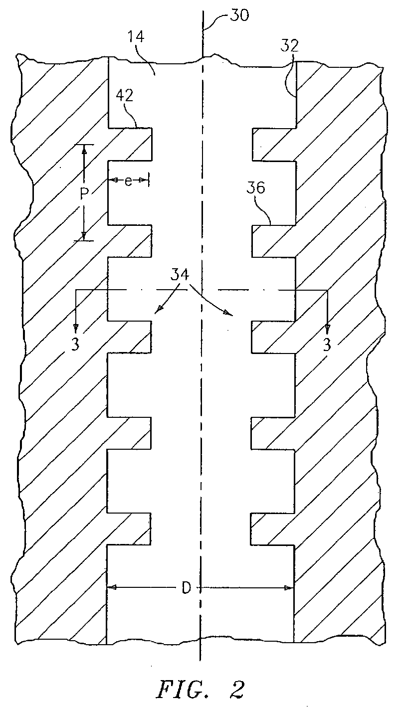
- FIGS. 2 and 3 there is shown a first embodiment of a cooling passageway 14 which has a circular cross-section.
- the cooling passageway 14 extends along an axis 30 from the root end 16 to the tip end 18 and has a wall 32.
- the wall 32 defines a passageway for the cooling fluid having a diameter D.
- a plurality of turbulation promotion devices 34 is incorporated into the passageway 14.
- the turbulation promotion devices may comprise arcuately shaped trip strips 36 which have a height e and which circumscribe an arc of less than 180 degrees.
- the ratio of e/D is preferably in the range of from 0.05 to 0.30.
- the turbulation promotion devices 34 comprises pairs of trip strips 36 formed on the wall 32.
- the trip strips 36 have end portions 38 and 40 which are spaced apart by a gap g.
- the gap g may be in the range of 1e to 4e. In a preferred embodiment, the gap g may be in the range of from 0.015 inches (0.38 mm) to 0.050 inches (1.27 mm).
- the trip strips 36 also have a surface 42 which is normal to the axis 30 as well as to the flow of the cooling fluid through the passageway 14.
- the gaps g are preferably oriented away from the maximum heat load.
- a plurality of pairs of trip strips 36 are positioned along the axis 30.
- the pairs of trip strips 36 are separated by a pitch P, which is the distance from the mid-point of a first trip strip 36 to a mid-point of a second trip strip 36.
- P the distance from the mid-point of a first trip strip 36 to a mid-point of a second trip strip 36.
- the ratio of P/e is in the range of from 5 to 30.
- the pairs of trip strips 36 are preferably aligned so that the gaps g of one pair of trip strips 36 are aligned with the gaps g of adjacent pairs of trip strips 36. It has been found that such an arrangement is very desirable from the standpoint of creating turbulence in the flow in the passageway 14 and minimizing the pressure drop of the flow.
- the turbulation promotion devices 34 may be notches 50 cut into the wall 32.
- each of the notches 50 may be arcuate in shape and may circumscribe an arc of less than 180 degrees.
- the notches may have a ratio of e/D which is in the range of from 0.05 to 0.30 and may have a surface 52 which is normal to the axis 30 and the flow of the cooling fluid through the passageway 14.
- the ratio of P/e is in the range of from 5 to 30.
- FIG. 5 there is shown an alternative embodiment of a cooling passageway 14 having turbulation promotion devices 60 which have a surface 62 which is at an angle ⁇ in the range of 30 degrees to 70 degrees, such as 45 degrees, with respect to the axis 30 and the flow of the cooling fluid through the passageway 14.
- the turbulation promotion devices may be either trip strips on the wall 32 or notches in the wall 32.
- the turbulation promotion devices 60 are preferably arcuate in shape and circumscribe an arc less than 180 degrees.
- the turbulation promotion devices 60 may be aligned pairs of devices 60 which have end portions spaced apart by a gap.
- the turbulation promotion devices of each pair may be offset along the axis 30. This has the benefit of a reduced pressure drop for an equivalent heat transfer level.
- the ratio P/e may be in the range of from 5 to 30.
- the turbulation promotion devices include a first set of trip strips 70 and a second set of trip strips 72.
- the first set of trip strips 70 are preferably offset from the second set of trip strips 72.
- the trip strips 70 and 72 are both arcuate in shape and circumscribe an arc of less than 180 degrees.
- the trip strips 70 and 72 have a ratio of e/D in the range of from 0.05 to 0.30.
- the ratio P/e for each of the sets is preferably in the range of from 5 to 30.
- the offset turbulation devices 80 take the form of a first set of notches 82 and a second set of offset notches 84.
- Each of the notches 82 and 84 is arcuate in shape and circumscribes an arc less than 180 degrees.
- Each of the notches 82 and 84 may have a ratio of e/D in the range of from 0.05 to 0.30. In this embodiment, as in the others, the ratio P/e for each set of notches is in the range of 5 to 30.
- the cooling passages shown in FIGS. 2 - 7 may be formed using any suitable technique known in the art.
- the cooling passageways 14 with the various turbulation promotion devices are formed using a STEM drilling technique.
- the cooling passages 14 have the turbulation hole configurations of FIGS. 2 - 7 exhibit improved cooling at a reduced pressure drop from the inlet of the passageway to the outlet of the passageway.
- the passageway 14 could have more than two aligned trip strips each separated from an adjacent trip strip 36 by a gap g.
- the passageway 14 could have four or eight aligned trip strips 36.
- each of the trip strips could circumscribe an arc which is less than 90 degrees.
- each of the trip strips could circumscribe an arc which less than 45 degrees.
Landscapes
- Engineering & Computer Science (AREA)
- Mechanical Engineering (AREA)
- General Engineering & Computer Science (AREA)
- Turbine Rotor Nozzle Sealing (AREA)
Abstract
Description
Claims (15)
- A turbine blade (10) comprising:an airfoil (13) having a root end (16) and a tip end (18);at least one cooling passageway (14) in said airfoil (13), said at least one cooling passageway (14) extending from the root end (16) to the tip end (18) and having a circular cross-section;a plurality of turbulation promotion devices (34) in said at least one cooling passageway (14); andeach of said turbulation promotion devices (34) being arcuate in shape and circumscribing an arc less than 180 degrees.
- A turbine blade according to claim 1, wherein said turbulation promotion devices comprise arcuately shaped trip strips (36;70,72).
- A turbine blade according to claim 1, wherein said turbulation promotion devices comprises a plurality of notches (50;82,84) cut into a wall of said at least one cooling passageway (14).
- A turbine blade according to claim 1, 2 or 3, wherein said plurality of turbulation promotion devices (34) includes a pair of aligned turbulation promotion devices (36), and end portions (38,40) of a first one of said pair of aligned turbulation promotion devices being spaced apart from end portions (38,40) of a second one of said pair of aligned turbulation promotion devices.
- A turbine blade according to claim 1, 2 or 3, wherein said plurality of turbulation promotion devices (34) includes at least two aligned turbulation promotion devices (36), and end portions (38,40) of one of said aligned promotion devices is spaced apart from end portions (38,40) of another of said aligned promotion devices.
- A turbine blade according to claim 4 or 5, wherein said end portions are spaced by a gap in the range of from 1e to 4e where e is the height of a turbulation promotion device and wherein each said passageway has a diameter D and each turbulation promotion device has a height e, and wherein the ratio of e/D is in the range of from 0.05 to 0.30.
- A turbine blade according to any preceding claim, wherein said plurality of turbulation promotion devices comprises a plurality of turbulation promotion devices aligned along an axis which extends from said root end (16) to said tip end (18), and wherein said plurality of turbulation promotion devices are separated by a pitch P, each of said turbulation promotion devices has a height e and a ratio of P/e is in the range of 5 to 30.
- A turbine blade according to claim 7, wherein said aligned turbulation promotion devices comprise pairs of aligned turbulators (36) with each pair of turbulators having spaced apart end portions (38,40) and wherein said spaced apart end portions of a first pair of turbulators is axially aligned with spaced apart end portions of adjacent pairs of turbulators.
- A turbine blade according to claim 1, 2 or 3, wherein said turbulation promotion devices comprise a first set of turbulators (70;82) and a second set of turbulators (72;84) offset from said first set of turbulators.
- A turbine blade according to any preceding claim, wherein each of said turbulation promotion devices has a surface (42;52) which is normal to an axis (30) extending from said tip end (18) to said root end (16).
- A turbine blade according to any of claims 1 to 9, wherein each of said turbulation promotion devices (60) has a surface (62) which is at an angle in the range of from 30 degrees to 70 degrees with respect to an axis (30) extending from said tip end (18) to said root end (16).
- A turbine blade according to any preceding claim, further comprising a plurality of cooling passageways (14) extending from said root end (16) to said tip end (18) and each of said cooling passageways (14) having a plurality of said turbulation promotion devices (34).
- A turbine blade according to claim 12, wherein said plurality of turbulation promotion devices (34) in each of said cooling passageways (14) has a surface (42;52) which is normal to a flow of cooling fluid through said cooling passageways (14).
- A turbine blade according to claim 12, wherein said plurality of turbulation promotion devices (60) in each of said cooling passageways (14) has a surface (62) which is at an angle in the range of from 30 degrees to 70 degrees with respect to a flow of cooling fluid through said cooling passageways (14).
- A turbine blade according to claim 12, 13 or 14, wherein said plurality of turbulation promotion devices in each of said cooling passageways includes a first set of turbulation promotion devices (70;82) which is offset from a second set of turbulation promotion devices (72;84).
Applications Claiming Priority (2)
| Application Number | Priority Date | Filing Date | Title |
|---|---|---|---|
| US774989 | 1996-12-27 | ||
| US10/774,989 US6997675B2 (en) | 2004-02-09 | 2004-02-09 | Turbulated hole configurations for turbine blades |
Publications (3)
| Publication Number | Publication Date |
|---|---|
| EP1561902A2 true EP1561902A2 (en) | 2005-08-10 |
| EP1561902A3 EP1561902A3 (en) | 2009-01-07 |
| EP1561902B1 EP1561902B1 (en) | 2013-05-01 |
Family
ID=34679418
Family Applications (1)
| Application Number | Title | Priority Date | Filing Date |
|---|---|---|---|
| EP05250703.5A Ceased EP1561902B1 (en) | 2004-02-09 | 2005-02-08 | Turbine blade comprising turbulation promotion devices |
Country Status (4)
| Country | Link |
|---|---|
| US (1) | US6997675B2 (en) |
| EP (1) | EP1561902B1 (en) |
| CN (1) | CN1654783A (en) |
| RU (1) | RU2299991C2 (en) |
Cited By (1)
| Publication number | Priority date | Publication date | Assignee | Title |
|---|---|---|---|---|
| EP2743454A1 (en) * | 2012-12-11 | 2014-06-18 | General Electric Company | Turbine component having cooling passages with varying diameter |
Families Citing this family (22)
| Publication number | Priority date | Publication date | Assignee | Title |
|---|---|---|---|---|
| US7185736B2 (en) * | 2003-08-25 | 2007-03-06 | Fisher Controls International Llc. | Aerodynamic noise abatement device and method for air-cooled condensing systems |
| FR2893080B1 (en) * | 2005-11-07 | 2012-12-28 | Snecma | COOLING ARRANGEMENT OF A DAWN OF A TURBINE, A TURBINE BLADE COMPRISING IT, TURBINE AND AIRCRAFT ENGINE WHICH ARE EQUIPPED |
| CN1318735C (en) * | 2005-12-26 | 2007-05-30 | 北京航空航天大学 | Pulsing impact cooling blade for gas turbine engine |
| US7938951B2 (en) * | 2007-03-22 | 2011-05-10 | General Electric Company | Methods and systems for forming tapered cooling holes |
| US7964087B2 (en) * | 2007-03-22 | 2011-06-21 | General Electric Company | Methods and systems for forming cooling holes having circular inlets and non-circular outlets |
| US20080230396A1 (en) * | 2007-03-22 | 2008-09-25 | General Electric Company | Methods and systems for forming turbulated cooling holes |
| US7901180B2 (en) * | 2007-05-07 | 2011-03-08 | United Technologies Corporation | Enhanced turbine airfoil cooling |
| US8764000B2 (en) * | 2007-06-28 | 2014-07-01 | United Technologies Corporation | Tool alignment fixture |
| RU2355890C1 (en) * | 2007-11-29 | 2009-05-20 | Открытое акционерное общество "Авиадвигатель" | High-temperature multi-stage gas turbine |
| US8511992B2 (en) * | 2008-01-22 | 2013-08-20 | United Technologies Corporation | Minimization of fouling and fluid losses in turbine airfoils |
| US8128366B2 (en) * | 2008-06-06 | 2012-03-06 | United Technologies Corporation | Counter-vortex film cooling hole design |
| US20090304494A1 (en) * | 2008-06-06 | 2009-12-10 | United Technologies Corporation | Counter-vortex paired film cooling hole design |
| GB2465337B (en) * | 2008-11-12 | 2012-01-11 | Rolls Royce Plc | A cooling arrangement |
| US8727724B2 (en) * | 2010-04-12 | 2014-05-20 | General Electric Company | Turbine bucket having a radial cooling hole |
| EP2971544B1 (en) * | 2013-03-14 | 2019-08-21 | United Technologies Corporation | Gas turbine engine component cooling with interleaved facing trip strips |
| US8985949B2 (en) * | 2013-04-29 | 2015-03-24 | Siemens Aktiengesellschaft | Cooling system including wavy cooling chamber in a trailing edge portion of an airfoil assembly |
| US10247099B2 (en) * | 2013-10-29 | 2019-04-02 | United Technologies Corporation | Pedestals with heat transfer augmenter |
| EP2944762B1 (en) * | 2014-05-12 | 2016-12-21 | General Electric Technology GmbH | Airfoil with improved cooling |
| US10533749B2 (en) * | 2015-10-27 | 2020-01-14 | Pratt & Whitney Cananda Corp. | Effusion cooling holes |
| US10871075B2 (en) | 2015-10-27 | 2020-12-22 | Pratt & Whitney Canada Corp. | Cooling passages in a turbine component |
| DE102019214667A1 (en) * | 2019-09-25 | 2021-03-25 | Siemens Aktiengesellschaft | Component with an area to be cooled and means for the additive manufacture of the same |
| JP7847031B2 (en) * | 2022-05-06 | 2026-04-16 | 三菱重工業株式会社 | Turbine blades and gas turbines |
Family Cites Families (13)
| Publication number | Priority date | Publication date | Assignee | Title |
|---|---|---|---|---|
| GB1596255A (en) * | 1973-07-26 | 1981-08-26 | Rolls Royce | Stator blade for a gas turbine engine |
| US5232343A (en) * | 1984-05-24 | 1993-08-03 | General Electric Company | Turbine blade |
| GB2159585B (en) * | 1984-05-24 | 1989-02-08 | Gen Electric | Turbine blade |
| SU1275962A1 (en) * | 1985-06-11 | 1996-01-27 | В.М. Брегман | Cooled turbine blade |
| SU1792118A1 (en) * | 1990-04-11 | 1996-03-20 | Центральный институт авиационного моторостроения им.П.И.Баранова | Cooled vane of gas turbine |
| US5695322A (en) * | 1991-12-17 | 1997-12-09 | General Electric Company | Turbine blade having restart turbulators |
| US5413463A (en) * | 1991-12-30 | 1995-05-09 | General Electric Company | Turbulated cooling passages in gas turbine buckets |
| US5660524A (en) * | 1992-07-13 | 1997-08-26 | General Electric Company | Airfoil blade having a serpentine cooling circuit and impingement cooling |
| US5975851A (en) * | 1997-12-17 | 1999-11-02 | United Technologies Corporation | Turbine blade with trailing edge root section cooling |
| US6234752B1 (en) * | 1999-08-16 | 2001-05-22 | General Electric Company | Method and tool for electrochemical machining |
| US6582584B2 (en) * | 1999-08-16 | 2003-06-24 | General Electric Company | Method for enhancing heat transfer inside a turbulated cooling passage |
| US6416283B1 (en) * | 2000-10-16 | 2002-07-09 | General Electric Company | Electrochemical machining process, electrode therefor and turbine bucket with turbulated cooling passage |
| US6672836B2 (en) * | 2001-12-11 | 2004-01-06 | United Technologies Corporation | Coolable rotor blade for an industrial gas turbine engine |
-
2004
- 2004-02-09 US US10/774,989 patent/US6997675B2/en not_active Expired - Lifetime
-
2005
- 2005-02-08 EP EP05250703.5A patent/EP1561902B1/en not_active Ceased
- 2005-02-08 CN CNA2005100516393A patent/CN1654783A/en active Pending
- 2005-02-09 RU RU2005103308/06A patent/RU2299991C2/en not_active IP Right Cessation
Cited By (1)
| Publication number | Priority date | Publication date | Assignee | Title |
|---|---|---|---|---|
| EP2743454A1 (en) * | 2012-12-11 | 2014-06-18 | General Electric Company | Turbine component having cooling passages with varying diameter |
Also Published As
| Publication number | Publication date |
|---|---|
| CN1654783A (en) | 2005-08-17 |
| RU2005103308A (en) | 2006-07-20 |
| US20050175454A1 (en) | 2005-08-11 |
| EP1561902B1 (en) | 2013-05-01 |
| EP1561902A3 (en) | 2009-01-07 |
| US6997675B2 (en) | 2006-02-14 |
| RU2299991C2 (en) | 2007-05-27 |
Similar Documents
| Publication | Publication Date | Title |
|---|---|---|
| US6997675B2 (en) | Turbulated hole configurations for turbine blades | |
| JP4063937B2 (en) | Turbulence promoting structure of cooling passage of blade in gas turbine engine | |
| US5797726A (en) | Turbulator configuration for cooling passages or rotor blade in a gas turbine engine | |
| US7841828B2 (en) | Turbine airfoil with submerged endwall cooling channel | |
| US8668453B2 (en) | Cooling system having reduced mass pin fins for components in a gas turbine engine | |
| EP1870561B1 (en) | Leading edge cooling of a gas turbine component using staggered turbulator strips | |
| EP2825748B1 (en) | Cooling channel for a gas turbine engine and gas turbine engine | |
| EP2823151B1 (en) | Airfoil with improved internal cooling channel pedestals | |
| US9797261B2 (en) | Internal cooling of engine components | |
| US8092176B2 (en) | Turbine airfoil cooling system with curved diffusion film cooling hole | |
| EP2107215B1 (en) | Gas turbine airfoil | |
| EP3436668B1 (en) | Turbine airfoil with turbulating feature on a cold wall | |
| US7766606B2 (en) | Turbine airfoil cooling system with platform cooling channels with diffusion slots | |
| US8876475B1 (en) | Turbine blade with radial cooling passage having continuous discrete turbulence air mixers | |
| US7637720B1 (en) | Turbulator for a turbine airfoil cooling passage | |
| EP1826361B1 (en) | Gas turbine engine aerofoil | |
| US7762775B1 (en) | Turbine airfoil with cooled thin trailing edge | |
| US7549843B2 (en) | Turbine airfoil cooling system with axial flowing serpentine cooling chambers | |
| US7510367B2 (en) | Turbine airfoil with endwall horseshoe cooling slot | |
| EP1561903B1 (en) | Tailored turbulation for turbine blades |
Legal Events
| Date | Code | Title | Description |
|---|---|---|---|
| PUAI | Public reference made under article 153(3) epc to a published international application that has entered the european phase |
Free format text: ORIGINAL CODE: 0009012 |
|
| AK | Designated contracting states |
Kind code of ref document: A2 Designated state(s): AT BE BG CH CY CZ DE DK EE ES FI FR GB GR HU IE IS IT LI LT LU MC NL PL PT RO SE SI SK TR |
|
| AX | Request for extension of the european patent |
Extension state: AL BA HR LV MK YU |
|
| PUAL | Search report despatched |
Free format text: ORIGINAL CODE: 0009013 |
|
| AK | Designated contracting states |
Kind code of ref document: A3 Designated state(s): AT BE BG CH CY CZ DE DK EE ES FI FR GB GR HU IE IS IT LI LT LU MC NL PL PT RO SE SI SK TR |
|
| AX | Request for extension of the european patent |
Extension state: AL BA HR LV MK YU |
|
| 17P | Request for examination filed |
Effective date: 20090706 |
|
| AKX | Designation fees paid |
Designated state(s): DE GB |
|
| 17Q | First examination report despatched |
Effective date: 20091019 |
|
| GRAP | Despatch of communication of intention to grant a patent |
Free format text: ORIGINAL CODE: EPIDOSNIGR1 |
|
| GRAS | Grant fee paid |
Free format text: ORIGINAL CODE: EPIDOSNIGR3 |
|
| GRAA | (expected) grant |
Free format text: ORIGINAL CODE: 0009210 |
|
| AK | Designated contracting states |
Kind code of ref document: B1 Designated state(s): DE GB |
|
| REG | Reference to a national code |
Ref country code: GB Ref legal event code: FG4D |
|
| REG | Reference to a national code |
Ref country code: DE Ref legal event code: R081 Ref document number: 602005039343 Country of ref document: DE Owner name: UNITED TECHNOLOGIES CORP. (N.D.GES.D. STAATES , US Free format text: FORMER OWNER: UNITED TECHNOLOGIES CORP. (N.D.GES.D. STAATES DELAWARE), HARTFORD, CONN., US |
|
| REG | Reference to a national code |
Ref country code: DE Ref legal event code: R096 Ref document number: 602005039343 Country of ref document: DE Effective date: 20130627 |
|
| PLBI | Opposition filed |
Free format text: ORIGINAL CODE: 0009260 |
|
| 26 | Opposition filed |
Opponent name: SIEMENS AKTIENGESELLSCHAFT Effective date: 20140131 |
|
| PLAX | Notice of opposition and request to file observation + time limit sent |
Free format text: ORIGINAL CODE: EPIDOSNOBS2 |
|
| REG | Reference to a national code |
Ref country code: DE Ref legal event code: R026 Ref document number: 602005039343 Country of ref document: DE Effective date: 20140131 |
|
| PLAF | Information modified related to communication of a notice of opposition and request to file observations + time limit |
Free format text: ORIGINAL CODE: EPIDOSCOBS2 |
|
| PLBB | Reply of patent proprietor to notice(s) of opposition received |
Free format text: ORIGINAL CODE: EPIDOSNOBS3 |
|
| PLAB | Opposition data, opponent's data or that of the opponent's representative modified |
Free format text: ORIGINAL CODE: 0009299OPPO |
|
| R26 | Opposition filed (corrected) |
Opponent name: SIEMENS AKTIENGESELLSCHAFT Effective date: 20140131 |
|
| REG | Reference to a national code |
Ref country code: DE Ref legal event code: R100 Ref document number: 602005039343 Country of ref document: DE |
|
| PLCK | Communication despatched that opposition was rejected |
Free format text: ORIGINAL CODE: EPIDOSNREJ1 |
|
| RAP2 | Party data changed (patent owner data changed or rights of a patent transferred) |
Owner name: UNITED TECHNOLOGIES CORPORATION |
|
| PLBN | Opposition rejected |
Free format text: ORIGINAL CODE: 0009273 |
|
| STAA | Information on the status of an ep patent application or granted ep patent |
Free format text: STATUS: OPPOSITION REJECTED |
|
| 27O | Opposition rejected |
Effective date: 20160620 |
|
| REG | Reference to a national code |
Ref country code: DE Ref legal event code: R082 Ref document number: 602005039343 Country of ref document: DE Representative=s name: SCHMITT-NILSON SCHRAUD WAIBEL WOHLFROM PATENTA, DE |
|
| REG | Reference to a national code |
Ref country code: DE Ref legal event code: R082 Ref document number: 602005039343 Country of ref document: DE Representative=s name: SCHMITT-NILSON SCHRAUD WAIBEL WOHLFROM PATENTA, DE Ref country code: DE Ref legal event code: R081 Ref document number: 602005039343 Country of ref document: DE Owner name: UNITED TECHNOLOGIES CORP. (N.D.GES.D. STAATES , US Free format text: FORMER OWNER: UNITED TECHNOLOGIES CORP., HARTFORD, CONN., US |
|
| PGFP | Annual fee paid to national office [announced via postgrant information from national office to epo] |
Ref country code: GB Payment date: 20200123 Year of fee payment: 16 Ref country code: DE Payment date: 20200121 Year of fee payment: 16 |
|
| REG | Reference to a national code |
Ref country code: DE Ref legal event code: R119 Ref document number: 602005039343 Country of ref document: DE |
|
| GBPC | Gb: european patent ceased through non-payment of renewal fee |
Effective date: 20210208 |
|
| PG25 | Lapsed in a contracting state [announced via postgrant information from national office to epo] |
Ref country code: GB Free format text: LAPSE BECAUSE OF NON-PAYMENT OF DUE FEES Effective date: 20210208 Ref country code: DE Free format text: LAPSE BECAUSE OF NON-PAYMENT OF DUE FEES Effective date: 20210901 |