EP1561614A1 - Steuersystem für eine aktive Fahrwerkstabilisierung - Google Patents
Steuersystem für eine aktive Fahrwerkstabilisierung Download PDFInfo
- Publication number
- EP1561614A1 EP1561614A1 EP05001202A EP05001202A EP1561614A1 EP 1561614 A1 EP1561614 A1 EP 1561614A1 EP 05001202 A EP05001202 A EP 05001202A EP 05001202 A EP05001202 A EP 05001202A EP 1561614 A1 EP1561614 A1 EP 1561614A1
- Authority
- EP
- European Patent Office
- Prior art keywords
- pump
- control system
- control unit
- motor
- port
- Prior art date
- Legal status (The legal status is an assumption and is not a legal conclusion. Google has not performed a legal analysis and makes no representation as to the accuracy of the status listed.)
- Granted
Links
- 230000006641 stabilisation Effects 0.000 title claims description 19
- 239000000725 suspension Substances 0.000 title description 3
- 239000003381 stabilizer Substances 0.000 claims abstract description 12
- 238000011105 stabilization Methods 0.000 claims description 18
- 238000010586 diagram Methods 0.000 description 1
- 239000012530 fluid Substances 0.000 description 1
- 238000012544 monitoring process Methods 0.000 description 1
Images
Classifications
-
- B—PERFORMING OPERATIONS; TRANSPORTING
- B60—VEHICLES IN GENERAL
- B60G—VEHICLE SUSPENSION ARRANGEMENTS
- B60G21/00—Interconnection systems for two or more resiliently-suspended wheels, e.g. for stabilising a vehicle body with respect to acceleration, deceleration or centrifugal forces
- B60G21/02—Interconnection systems for two or more resiliently-suspended wheels, e.g. for stabilising a vehicle body with respect to acceleration, deceleration or centrifugal forces permanently interconnected
- B60G21/04—Interconnection systems for two or more resiliently-suspended wheels, e.g. for stabilising a vehicle body with respect to acceleration, deceleration or centrifugal forces permanently interconnected mechanically
- B60G21/05—Interconnection systems for two or more resiliently-suspended wheels, e.g. for stabilising a vehicle body with respect to acceleration, deceleration or centrifugal forces permanently interconnected mechanically between wheels on the same axle but on different sides of the vehicle, i.e. the left and right wheel suspensions being interconnected
- B60G21/055—Stabiliser bars
- B60G21/0551—Mounting means therefor
- B60G21/0553—Mounting means therefor adjustable
- B60G21/0555—Mounting means therefor adjustable including an actuator inducing vehicle roll
-
- B—PERFORMING OPERATIONS; TRANSPORTING
- B60—VEHICLES IN GENERAL
- B60G—VEHICLE SUSPENSION ARRANGEMENTS
- B60G17/00—Resilient suspensions having means for adjusting the spring or vibration-damper characteristics, for regulating the distance between a supporting surface and a sprung part of vehicle or for locking suspension during use to meet varying vehicular or surface conditions, e.g. due to speed or load
- B60G17/015—Resilient suspensions having means for adjusting the spring or vibration-damper characteristics, for regulating the distance between a supporting surface and a sprung part of vehicle or for locking suspension during use to meet varying vehicular or surface conditions, e.g. due to speed or load the regulating means comprising electric or electronic elements
- B60G17/016—Resilient suspensions having means for adjusting the spring or vibration-damper characteristics, for regulating the distance between a supporting surface and a sprung part of vehicle or for locking suspension during use to meet varying vehicular or surface conditions, e.g. due to speed or load the regulating means comprising electric or electronic elements characterised by their responsiveness, when the vehicle is travelling, to specific motion, a specific condition, or driver input
- B60G17/0162—Resilient suspensions having means for adjusting the spring or vibration-damper characteristics, for regulating the distance between a supporting surface and a sprung part of vehicle or for locking suspension during use to meet varying vehicular or surface conditions, e.g. due to speed or load the regulating means comprising electric or electronic elements characterised by their responsiveness, when the vehicle is travelling, to specific motion, a specific condition, or driver input mainly during a motion involving steering operation, e.g. cornering, overtaking
-
- B—PERFORMING OPERATIONS; TRANSPORTING
- B60—VEHICLES IN GENERAL
- B60G—VEHICLE SUSPENSION ARRANGEMENTS
- B60G2202/00—Indexing codes relating to the type of spring, damper or actuator
- B60G2202/10—Type of spring
- B60G2202/13—Torsion spring
- B60G2202/135—Stabiliser bar and/or tube
-
- B—PERFORMING OPERATIONS; TRANSPORTING
- B60—VEHICLES IN GENERAL
- B60G—VEHICLE SUSPENSION ARRANGEMENTS
- B60G2202/00—Indexing codes relating to the type of spring, damper or actuator
- B60G2202/40—Type of actuator
- B60G2202/41—Fluid actuator
- B60G2202/413—Hydraulic actuator
-
- B—PERFORMING OPERATIONS; TRANSPORTING
- B60—VEHICLES IN GENERAL
- B60G—VEHICLE SUSPENSION ARRANGEMENTS
- B60G2202/00—Indexing codes relating to the type of spring, damper or actuator
- B60G2202/40—Type of actuator
- B60G2202/41—Fluid actuator
- B60G2202/416—Fluid actuator using a pump, e.g. in the line connecting the lower chamber to the upper chamber of the actuator
-
- B—PERFORMING OPERATIONS; TRANSPORTING
- B60—VEHICLES IN GENERAL
- B60G—VEHICLE SUSPENSION ARRANGEMENTS
- B60G2500/00—Indexing codes relating to the regulated action or device
- B60G2500/02—Supply or exhaust flow rates; Pump operation
-
- B—PERFORMING OPERATIONS; TRANSPORTING
- B60—VEHICLES IN GENERAL
- B60G—VEHICLE SUSPENSION ARRANGEMENTS
- B60G2800/00—Indexing codes relating to the type of movement or to the condition of the vehicle and to the end result to be achieved by the control action
- B60G2800/01—Attitude or posture control
- B60G2800/012—Rolling condition
Definitions
- the invention relates to a control system for active chassis stabilization a vehicle having at least one coupled to a stabilizer of the vehicle, hydraulically operated actuator and a via a chassis stabilization control unit controlled pump.
- the invention provides a control system for active chassis stabilization, which allows a reduction in the length of the hose lines.
- a control system with a closed hydraulic circuit requires only relatively short hose lines, especially if for the front and the rear vehicle area separate actuators are provided with their own hydraulic circuits, the relatively easy to control.
- the actuator is connected via two separate lines to a pressure and a suction port of the pump connected.
- a flexible and thereby simpler actuator operation results from the fact that the Pump has a first and a second terminal and reversibly operated can be so that in a first mode of operation of the pump the first Connect a pressure connection and the second connection a suction connection and in a second mode of operation, the first port has a suction port and the second port represents a pressure connection. So can by appropriate Control with only one pump actuator movements in two opposite Directions are reached.
- the pump is part a preassembled motor / pump assembly, further comprising a drive motor and an electronic control unit.
- a compact manufacturable Motor-pump unit will be the previously required hydraulic pump unit and the valve block completely replaced by the control unit.
- the chassis stabilization control unit can be connected to the control unit of the Motor / pump unit connected via a local CAN bus or alternatively be integrated into the control unit of the motor / pump unit.
- the engine power can be an electric with the chassis stabilization control unit connected, connected to the hydraulic circuit Be provided pressure transducer.
- an actuator for the deflection of the stabilizer can in particular a in the center of the stabilizer arranged pivot motor can be used.
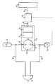
- the essential components of the control system shown in the figure are a hydraulically operated rotary actuator 10, a motor / pump unit 12, a hydraulic accumulator 14, a pressure transducer 16 and a chassis stabilization control unit 18th
- the per se known motor / pump unit 12 is a compact, preassembled Assembly comprising a pump 20, a drive motor 22 and an electronic Control unit 24 includes.
- the pump 20 has two with the rotary actuator 10 connected outlets 26, 28 and can be reversibly operated, i. the Pump ports 26 and 28 can either as a pressure or suction or as Suction or pressure connection to be operated.
- the control of the drive motor 22 takes over the housed in the motor / pump unit 12 electronic Control unit 24.
- the rotary actuator 10 is preferably a swing motor which is connected to a (not shown) stabilizer of the vehicle is coupled.
- the rotary actuator 10 is in the Arranged in the middle of the stabilizer and able to limit the stabilizer Dimensions to rotate about an axis parallel to the direction of travel of the vehicle. Due to the reversibility of the pump 20, the rotation of the stabilizer with Help the Drehaktuators 10 as needed clockwise or counterclockwise respectively.
- the one shown in the figure, via the two separate lines 30, 32nd made connection of the rotary actuator 10 with the two pump connections 26, 28 represents a closed hydraulic circuit, wherein the to the Circuit connected "pre-charged" (i.e., pressurized) hydraulic Accumulator 14 in operation or other minor over time Compensates for fluid losses.
- a fluid volume of the accumulator of less than 0.2 1 is sufficient.
- the chassis stabilization control unit 18 is on the one hand via a vehicle bus 34 with the already existing vehicle sensors 36 and on the other hand via a local bus 38 or directly with the Control unit 24 of the motor / pump unit 12 connected. Depending on respective state of the chassis stabilization system and / or the vehicle the chassis stabilization control unit 18 controls the motor / pump unit 12, which then causes a corresponding rotation of the rotary actuator 10.
Landscapes
- Engineering & Computer Science (AREA)
- Mechanical Engineering (AREA)
- Vehicle Body Suspensions (AREA)
Abstract
Description
Claims (9)
- Steuersystem für eine aktive Fahrwerkstabilisierung eines Fahrzeugs, mit wenigstens einem an einen Stabilisator des Fahrzeugs gekoppelten, hydraulisch betriebenen Aktuator (10) und einer über eine Fahrwerkstabilisierungs-Steuereinheit (18) angesteuerten Pumpe (20), dadurch gekennzeichnet, daß der Aktuator (10) unter Bildung eines geschlossenen hydraulischen Kreislaufs an die Pumpe (20) angeschlossen ist.
- Steuersystem nach Anspruch 1, dadurch gekennzeichnet, daß der Aktuator (10) über zwei separate Leitungen (30, 32) an einen Druck- und einen Sauganschluß der Pumpe (20) angeschlossen ist.
- Steuersystem nach Anspruch 2, dadurch gekennzeichnet, daß die Pumpe (20) einen ersten und einen zweiten Anschluß (26) bzw. (28) aufweist und reversibel betrieben werden kann, so daß in einem ersten Betriebsmodus der Pumpe (20) der erste Anschluß (26) einen Druckanschluß und der zweite Anschluß (28) einen Sauganschluß und in einem zweiten Betriebsmodus der erste Anschluß (26) einen Sauganschluß und der zweite Anschluß (28) einen Druckanschluß darstellt.
- Steuersystem nach einem der vorhergehenden Ansprüche, dadurch gekennzeichnet, daß die Pumpe (20) Teil eines vormontierten Motor/PumpenAggregats (12) ist, das ferner einen Antriebsmotor (22) und eine elektronische Steuereinheit (24) umfaßt.
- Steuersystem nach Anspruch 4, dadurch gekennzeichnet, daß die Fahrwerkstabilisierungs-Steuereinheit (18) mit der Steuereinheit (24) des Motor/Pumpen-Aggregats (12) über einen lokalen Bus (38) verbunden ist.
- Steuersystem nach einem der Ansprüche 1 bis 4, dadurch gekennzeichnet, daß die Fahrwerkstabilisierungs-Steuereinheit (18) in die Steuereinheit (24) des Motor/Pumpen-Aggregats (12) integriert ist.
- Steuersystem nach einem der vorhergehenden Ansprüche, dadurch gekennzeichnet, daß ein hydraulischer Akkumulator (14) an den hydraulischen Kreislauf angeschlossen ist.
- Steuersystem nach einem der vorhergehenden Ansprüche, dadurch gekennzeichnet, daß ein elektrisch mit der Fahrwerkstabilisierungs-Steuereinheit verbundener Druckwandler (16) an den hydraulischen Kreislauf angeschlossen ist.
- Steuersystem nach einem der vorhergehenden Ansprüche, dadurch gekennzeichnet, daß der Aktuator (10) ein in der Mitte des Stabilisators angeordneter Schwenkmotor ist.
Applications Claiming Priority (2)
| Application Number | Priority Date | Filing Date | Title |
|---|---|---|---|
| DE202004001668U | 2004-02-04 | ||
| DE200420001668 DE202004001668U1 (de) | 2004-02-04 | 2004-02-04 | Steuersystem für eine aktive Fahrwerkstabilisierung |
Publications (2)
| Publication Number | Publication Date |
|---|---|
| EP1561614A1 true EP1561614A1 (de) | 2005-08-10 |
| EP1561614B1 EP1561614B1 (de) | 2008-07-09 |
Family
ID=32520441
Family Applications (1)
| Application Number | Title | Priority Date | Filing Date |
|---|---|---|---|
| EP20050001202 Ceased EP1561614B1 (de) | 2004-02-04 | 2005-01-21 | Steuersystem für eine aktive Fahrwerkstabilisierung |
Country Status (3)
| Country | Link |
|---|---|
| EP (1) | EP1561614B1 (de) |
| JP (1) | JP2005219730A (de) |
| DE (2) | DE202004001668U1 (de) |
Cited By (1)
| Publication number | Priority date | Publication date | Assignee | Title |
|---|---|---|---|---|
| US7959164B2 (en) * | 2007-03-23 | 2011-06-14 | Arvinmeritor Technology, Llc | Roll control devices |
Families Citing this family (3)
| Publication number | Priority date | Publication date | Assignee | Title |
|---|---|---|---|---|
| DE102004048085A1 (de) * | 2004-09-30 | 2006-04-06 | Zf Friedrichshafen Ag | Schaltbarer Stabilisator für ein Kraftfahrzeug |
| DE102005031766A1 (de) * | 2005-07-07 | 2007-01-18 | Zf Friedrichshafen Ag | Dämpfereinrichtung für das Fahrwerk eines Kraftfahrzeugs |
| DE102006054994A1 (de) * | 2006-11-22 | 2008-05-29 | Zf Friedrichshafen Ag | Wankstabilisierungssystem |
Citations (5)
| Publication number | Priority date | Publication date | Assignee | Title |
|---|---|---|---|---|
| WO1996027508A1 (de) * | 1995-03-07 | 1996-09-12 | Franz Tuczek | Neigungsausgleich für fahrzeuge |
| US5735540A (en) * | 1995-04-08 | 1998-04-07 | Fichtel & Sachs Ag | Dual-circuit hydraulic system for an active vehicle suspension control system |
| GB2349368A (en) * | 1999-04-29 | 2000-11-01 | Rover Group | Vehicle suspensions |
| US6179310B1 (en) * | 1996-12-14 | 2001-01-30 | Rover Group Limited | Vehicle roll stabilizing system |
| DE10213156A1 (de) * | 2002-03-23 | 2003-10-02 | Daimler Chrysler Ag | Aktive Federung für ein Kraftfahrzeug |
Family Cites Families (2)
| Publication number | Priority date | Publication date | Assignee | Title |
|---|---|---|---|---|
| JPS63215411A (ja) * | 1987-03-02 | 1988-09-07 | Kayaba Ind Co Ltd | サスペンシヨン制御装置 |
| GB2350591B (en) * | 1999-06-04 | 2003-05-14 | Delphi Tech Inc | Roll control actuator |
-
2004
- 2004-02-04 DE DE200420001668 patent/DE202004001668U1/de not_active Expired - Lifetime
-
2005
- 2005-01-21 EP EP20050001202 patent/EP1561614B1/de not_active Ceased
- 2005-01-21 DE DE200550004600 patent/DE502005004600D1/de not_active Expired - Lifetime
- 2005-02-01 JP JP2005024816A patent/JP2005219730A/ja active Pending
Patent Citations (5)
| Publication number | Priority date | Publication date | Assignee | Title |
|---|---|---|---|---|
| WO1996027508A1 (de) * | 1995-03-07 | 1996-09-12 | Franz Tuczek | Neigungsausgleich für fahrzeuge |
| US5735540A (en) * | 1995-04-08 | 1998-04-07 | Fichtel & Sachs Ag | Dual-circuit hydraulic system for an active vehicle suspension control system |
| US6179310B1 (en) * | 1996-12-14 | 2001-01-30 | Rover Group Limited | Vehicle roll stabilizing system |
| GB2349368A (en) * | 1999-04-29 | 2000-11-01 | Rover Group | Vehicle suspensions |
| DE10213156A1 (de) * | 2002-03-23 | 2003-10-02 | Daimler Chrysler Ag | Aktive Federung für ein Kraftfahrzeug |
Cited By (1)
| Publication number | Priority date | Publication date | Assignee | Title |
|---|---|---|---|---|
| US7959164B2 (en) * | 2007-03-23 | 2011-06-14 | Arvinmeritor Technology, Llc | Roll control devices |
Also Published As
| Publication number | Publication date |
|---|---|
| DE202004001668U1 (de) | 2004-06-17 |
| JP2005219730A (ja) | 2005-08-18 |
| EP1561614B1 (de) | 2008-07-09 |
| DE502005004600D1 (de) | 2008-08-21 |
Similar Documents
| Publication | Publication Date | Title |
|---|---|---|
| EP3433147B1 (de) | Betätigungsvorrichtung für ein hydraulisches betätigungssystem | |
| DE10337954A1 (de) | Hilfskraftunterstütztes Lenksystem für ein Kraftfahrzeug, mit hydraulischer offener Mitte | |
| EP1561614B1 (de) | Steuersystem für eine aktive Fahrwerkstabilisierung | |
| DE102004030009A1 (de) | Hydraulische Steuervorrichtung | |
| DE102022208247A1 (de) | Kraftübertragungseinheit und Bremssysteme, die diese verwenden | |
| DE102016106595A1 (de) | Großmanipulator mit dezentraler Hydraulik | |
| EP1342597B1 (de) | Anordnung zur aktiven Rollstabilisierung eines Kraftfahrzeugs | |
| DE102014200653A1 (de) | Pumpengehäuse für ein Hydro-Aggregat | |
| DE102005042771A1 (de) | Hilfskraftlenkungssystem | |
| DE10301752B4 (de) | Verfahren zur Bemessung eines Lenkölstromes und hydraulische Lenkeinrichtung mit Stromverstärkung | |
| EP2617626B1 (de) | Lenksystem | |
| EP4442475A1 (de) | Hydraulikbaukasten | |
| DE3437231A1 (de) | Servolenkung fuer fahrzeuge | |
| DE102020116290A1 (de) | Aktives Fahrwerksystem für ein Kraftfahrzeug mit zwei Fahrzeugachsen | |
| DE102009041022B4 (de) | Lageranordnung eines Stabilisators im Fahrwerk eines Fahrzeugs | |
| EP1426209B1 (de) | Hydraulisches Stabilisierungssystem | |
| DE112023003084T5 (de) | Lenkgetriebe | |
| WO2002024509A1 (de) | Hydraulische servolenkung in integrierter bauweise | |
| DE102011076849A1 (de) | Fahrwerkssystem | |
| WO1989004269A1 (fr) | Dispositif de direction pour roues avant et arriere dirigeables de vehicules | |
| DE102004040940A1 (de) | Baugruppe für ein Fahrwerkstabilisierungssystem | |
| DE102009052687A1 (de) | Kalibrierverfahren und hydraulischer Fahrantrieb | |
| DE102005047278A1 (de) | Schwenkmotor-Anordnung in einem geteilten Stabilisator eines Fahrzeugs | |
| EP1925473A2 (de) | Wankstabilisierungssystem | |
| WO2003047949A1 (de) | Zweikreisiges steer-by-wire-lenksystem mit zwei hydraulisch betriebenen stellaggregaten |
Legal Events
| Date | Code | Title | Description |
|---|---|---|---|
| PUAI | Public reference made under article 153(3) epc to a published international application that has entered the european phase |
Free format text: ORIGINAL CODE: 0009012 |
|
| AK | Designated contracting states |
Kind code of ref document: A1 Designated state(s): AT BE BG CH CY CZ DE DK EE ES FI FR GB GR HU IE IS IT LI LT LU MC NL PL PT RO SE SI SK TR |
|
| AX | Request for extension of the european patent |
Extension state: AL BA HR LV MK YU |
|
| 17P | Request for examination filed |
Effective date: 20060131 |
|
| AKX | Designation fees paid |
Designated state(s): DE FR GB IT |
|
| 17Q | First examination report despatched |
Effective date: 20061107 |
|
| GRAP | Despatch of communication of intention to grant a patent |
Free format text: ORIGINAL CODE: EPIDOSNIGR1 |
|
| GRAS | Grant fee paid |
Free format text: ORIGINAL CODE: EPIDOSNIGR3 |
|
| GRAA | (expected) grant |
Free format text: ORIGINAL CODE: 0009210 |
|
| AK | Designated contracting states |
Kind code of ref document: B1 Designated state(s): DE FR GB IT |
|
| REG | Reference to a national code |
Ref country code: GB Ref legal event code: FG4D Free format text: NOT ENGLISH |
|
| REF | Corresponds to: |
Ref document number: 502005004600 Country of ref document: DE Date of ref document: 20080821 Kind code of ref document: P |
|
| PLBE | No opposition filed within time limit |
Free format text: ORIGINAL CODE: 0009261 |
|
| STAA | Information on the status of an ep patent application or granted ep patent |
Free format text: STATUS: NO OPPOSITION FILED WITHIN TIME LIMIT |
|
| 26N | No opposition filed |
Effective date: 20090414 |
|
| REG | Reference to a national code |
Ref country code: FR Ref legal event code: PLFP Year of fee payment: 12 |
|
| REG | Reference to a national code |
Ref country code: FR Ref legal event code: PLFP Year of fee payment: 13 |
|
| REG | Reference to a national code |
Ref country code: FR Ref legal event code: PLFP Year of fee payment: 14 |
|
| PGFP | Annual fee paid to national office [announced via postgrant information from national office to epo] |
Ref country code: GB Payment date: 20220127 Year of fee payment: 18 Ref country code: DE Payment date: 20220127 Year of fee payment: 18 |
|
| PGFP | Annual fee paid to national office [announced via postgrant information from national office to epo] |
Ref country code: IT Payment date: 20220119 Year of fee payment: 18 Ref country code: FR Payment date: 20220125 Year of fee payment: 18 |
|
| REG | Reference to a national code |
Ref country code: DE Ref legal event code: R119 Ref document number: 502005004600 Country of ref document: DE |
|
| GBPC | Gb: european patent ceased through non-payment of renewal fee |
Effective date: 20230121 |
|
| PG25 | Lapsed in a contracting state [announced via postgrant information from national office to epo] |
Ref country code: GB Free format text: LAPSE BECAUSE OF NON-PAYMENT OF DUE FEES Effective date: 20230121 Ref country code: DE Free format text: LAPSE BECAUSE OF NON-PAYMENT OF DUE FEES Effective date: 20230801 |
|
| PG25 | Lapsed in a contracting state [announced via postgrant information from national office to epo] |
Ref country code: FR Free format text: LAPSE BECAUSE OF NON-PAYMENT OF DUE FEES Effective date: 20230131 |
|
| PG25 | Lapsed in a contracting state [announced via postgrant information from national office to epo] |
Ref country code: IT Free format text: LAPSE BECAUSE OF NON-PAYMENT OF DUE FEES Effective date: 20230121 |