EP1561530A1 - Alloy nano-particle and method for production thereof, and magnetic recording medium using alloy nano-particle - Google Patents
Alloy nano-particle and method for production thereof, and magnetic recording medium using alloy nano-particle Download PDFInfo
- Publication number
- EP1561530A1 EP1561530A1 EP03811485A EP03811485A EP1561530A1 EP 1561530 A1 EP1561530 A1 EP 1561530A1 EP 03811485 A EP03811485 A EP 03811485A EP 03811485 A EP03811485 A EP 03811485A EP 1561530 A1 EP1561530 A1 EP 1561530A1
- Authority
- EP
- European Patent Office
- Prior art keywords
- nanoparticles
- magnetic
- substrate
- layer
- alloy nanoparticles
- Prior art date
- Legal status (The legal status is an assumption and is not a legal conclusion. Google has not performed a legal analysis and makes no representation as to the accuracy of the status listed.)
- Withdrawn
Links
Images










Classifications
-
- B—PERFORMING OPERATIONS; TRANSPORTING
- B22—CASTING; POWDER METALLURGY
- B22F—WORKING METALLIC POWDER; MANUFACTURE OF ARTICLES FROM METALLIC POWDER; MAKING METALLIC POWDER; APPARATUS OR DEVICES SPECIALLY ADAPTED FOR METALLIC POWDER
- B22F9/00—Making metallic powder or suspensions thereof
- B22F9/16—Making metallic powder or suspensions thereof using chemical processes
- B22F9/18—Making metallic powder or suspensions thereof using chemical processes with reduction of metal compounds
- B22F9/24—Making metallic powder or suspensions thereof using chemical processes with reduction of metal compounds starting from liquid metal compounds, e.g. solutions
-
- B—PERFORMING OPERATIONS; TRANSPORTING
- B22—CASTING; POWDER METALLURGY
- B22F—WORKING METALLIC POWDER; MANUFACTURE OF ARTICLES FROM METALLIC POWDER; MAKING METALLIC POWDER; APPARATUS OR DEVICES SPECIALLY ADAPTED FOR METALLIC POWDER
- B22F1/00—Metallic powder; Treatment of metallic powder, e.g. to facilitate working or to improve properties
- B22F1/05—Metallic powder characterised by the size or surface area of the particles
- B22F1/052—Metallic powder characterised by the size or surface area of the particles characterised by a mixture of particles of different sizes or by the particle size distribution
-
- B—PERFORMING OPERATIONS; TRANSPORTING
- B22—CASTING; POWDER METALLURGY
- B22F—WORKING METALLIC POWDER; MANUFACTURE OF ARTICLES FROM METALLIC POWDER; MAKING METALLIC POWDER; APPARATUS OR DEVICES SPECIALLY ADAPTED FOR METALLIC POWDER
- B22F1/00—Metallic powder; Treatment of metallic powder, e.g. to facilitate working or to improve properties
- B22F1/05—Metallic powder characterised by the size or surface area of the particles
- B22F1/054—Nanosized particles
-
- B—PERFORMING OPERATIONS; TRANSPORTING
- B22—CASTING; POWDER METALLURGY
- B22F—WORKING METALLIC POWDER; MANUFACTURE OF ARTICLES FROM METALLIC POWDER; MAKING METALLIC POWDER; APPARATUS OR DEVICES SPECIALLY ADAPTED FOR METALLIC POWDER
- B22F9/00—Making metallic powder or suspensions thereof
- B22F9/16—Making metallic powder or suspensions thereof using chemical processes
- B22F9/30—Making metallic powder or suspensions thereof using chemical processes with decomposition of metal compounds, e.g. by pyrolysis
- B22F9/305—Making metallic powder or suspensions thereof using chemical processes with decomposition of metal compounds, e.g. by pyrolysis of metal carbonyls
-
- B—PERFORMING OPERATIONS; TRANSPORTING
- B82—NANOTECHNOLOGY
- B82Y—SPECIFIC USES OR APPLICATIONS OF NANOSTRUCTURES; MEASUREMENT OR ANALYSIS OF NANOSTRUCTURES; MANUFACTURE OR TREATMENT OF NANOSTRUCTURES
- B82Y25/00—Nanomagnetism, e.g. magnetoimpedance, anisotropic magnetoresistance, giant magnetoresistance or tunneling magnetoresistance
-
- B—PERFORMING OPERATIONS; TRANSPORTING
- B82—NANOTECHNOLOGY
- B82Y—SPECIFIC USES OR APPLICATIONS OF NANOSTRUCTURES; MEASUREMENT OR ANALYSIS OF NANOSTRUCTURES; MANUFACTURE OR TREATMENT OF NANOSTRUCTURES
- B82Y30/00—Nanotechnology for materials or surface science, e.g. nanocomposites
-
- G—PHYSICS
- G11—INFORMATION STORAGE
- G11B—INFORMATION STORAGE BASED ON RELATIVE MOVEMENT BETWEEN RECORD CARRIER AND TRANSDUCER
- G11B5/00—Recording by magnetisation or demagnetisation of a record carrier; Reproducing by magnetic means; Record carriers therefor
- G11B5/62—Record carriers characterised by the selection of the material
- G11B5/68—Record carriers characterised by the selection of the material comprising one or more layers of magnetisable material homogeneously mixed with a bonding agent
- G11B5/70—Record carriers characterised by the selection of the material comprising one or more layers of magnetisable material homogeneously mixed with a bonding agent on a base layer
- G11B5/706—Record carriers characterised by the selection of the material comprising one or more layers of magnetisable material homogeneously mixed with a bonding agent on a base layer characterised by the composition of the magnetic material
- G11B5/70605—Record carriers characterised by the selection of the material comprising one or more layers of magnetisable material homogeneously mixed with a bonding agent on a base layer characterised by the composition of the magnetic material metals or alloys
- G11B5/70615—Record carriers characterised by the selection of the material comprising one or more layers of magnetisable material homogeneously mixed with a bonding agent on a base layer characterised by the composition of the magnetic material metals or alloys containing Fe metal or alloys
-
- G—PHYSICS
- G11—INFORMATION STORAGE
- G11B—INFORMATION STORAGE BASED ON RELATIVE MOVEMENT BETWEEN RECORD CARRIER AND TRANSDUCER
- G11B5/00—Recording by magnetisation or demagnetisation of a record carrier; Reproducing by magnetic means; Record carriers therefor
- G11B5/62—Record carriers characterised by the selection of the material
- G11B5/68—Record carriers characterised by the selection of the material comprising one or more layers of magnetisable material homogeneously mixed with a bonding agent
- G11B5/70—Record carriers characterised by the selection of the material comprising one or more layers of magnetisable material homogeneously mixed with a bonding agent on a base layer
- G11B5/714—Record carriers characterised by the selection of the material comprising one or more layers of magnetisable material homogeneously mixed with a bonding agent on a base layer characterised by the dimension of the magnetic particles
-
- G—PHYSICS
- G11—INFORMATION STORAGE
- G11B—INFORMATION STORAGE BASED ON RELATIVE MOVEMENT BETWEEN RECORD CARRIER AND TRANSDUCER
- G11B5/00—Recording by magnetisation or demagnetisation of a record carrier; Reproducing by magnetic means; Record carriers therefor
- G11B5/62—Record carriers characterised by the selection of the material
- G11B5/72—Protective coatings, e.g. anti-static or antifriction
- G11B5/727—Inorganic carbon protective coating, e.g. graphite, diamond like carbon or doped carbon
-
- G—PHYSICS
- G11—INFORMATION STORAGE
- G11B—INFORMATION STORAGE BASED ON RELATIVE MOVEMENT BETWEEN RECORD CARRIER AND TRANSDUCER
- G11B5/00—Recording by magnetisation or demagnetisation of a record carrier; Reproducing by magnetic means; Record carriers therefor
- G11B5/62—Record carriers characterised by the selection of the material
- G11B5/73—Base layers, i.e. all non-magnetic layers lying under a lowermost magnetic recording layer, e.g. including any non-magnetic layer in between a first magnetic recording layer and either an underlying substrate or a soft magnetic underlayer
- G11B5/7368—Non-polymeric layer under the lowermost magnetic recording layer
- G11B5/7373—Non-magnetic single underlayer comprising chromium
-
- G—PHYSICS
- G11—INFORMATION STORAGE
- G11B—INFORMATION STORAGE BASED ON RELATIVE MOVEMENT BETWEEN RECORD CARRIER AND TRANSDUCER
- G11B5/00—Recording by magnetisation or demagnetisation of a record carrier; Reproducing by magnetic means; Record carriers therefor
- G11B5/62—Record carriers characterised by the selection of the material
- G11B5/73—Base layers, i.e. all non-magnetic layers lying under a lowermost magnetic recording layer, e.g. including any non-magnetic layer in between a first magnetic recording layer and either an underlying substrate or a soft magnetic underlayer
- G11B5/739—Magnetic recording media substrates
- G11B5/73911—Inorganic substrates
- G11B5/73913—Composites or coated substrates
-
- G—PHYSICS
- G11—INFORMATION STORAGE
- G11B—INFORMATION STORAGE BASED ON RELATIVE MOVEMENT BETWEEN RECORD CARRIER AND TRANSDUCER
- G11B5/00—Recording by magnetisation or demagnetisation of a record carrier; Reproducing by magnetic means; Record carriers therefor
- G11B5/62—Record carriers characterised by the selection of the material
- G11B5/73—Base layers, i.e. all non-magnetic layers lying under a lowermost magnetic recording layer, e.g. including any non-magnetic layer in between a first magnetic recording layer and either an underlying substrate or a soft magnetic underlayer
- G11B5/739—Magnetic recording media substrates
- G11B5/73911—Inorganic substrates
- G11B5/73921—Glass or ceramic substrates
-
- G—PHYSICS
- G11—INFORMATION STORAGE
- G11B—INFORMATION STORAGE BASED ON RELATIVE MOVEMENT BETWEEN RECORD CARRIER AND TRANSDUCER
- G11B5/00—Recording by magnetisation or demagnetisation of a record carrier; Reproducing by magnetic means; Record carriers therefor
- G11B5/84—Processes or apparatus specially adapted for manufacturing record carriers
- G11B5/842—Coating a support with a liquid magnetic dispersion
-
- H—ELECTRICITY
- H01—ELECTRIC ELEMENTS
- H01F—MAGNETS; INDUCTANCES; TRANSFORMERS; SELECTION OF MATERIALS FOR THEIR MAGNETIC PROPERTIES
- H01F1/00—Magnets or magnetic bodies characterised by the magnetic materials therefor; Selection of materials for their magnetic properties
- H01F1/0036—Magnets or magnetic bodies characterised by the magnetic materials therefor; Selection of materials for their magnetic properties showing low dimensional magnetism, i.e. spin rearrangements due to a restriction of dimensions, e.g. showing giant magnetoresistivity
- H01F1/0045—Zero dimensional, e.g. nanoparticles, soft nanoparticles for medical/biological use
- H01F1/0063—Zero dimensional, e.g. nanoparticles, soft nanoparticles for medical/biological use in a non-magnetic matrix, e.g. granular solids
-
- B—PERFORMING OPERATIONS; TRANSPORTING
- B22—CASTING; POWDER METALLURGY
- B22F—WORKING METALLIC POWDER; MANUFACTURE OF ARTICLES FROM METALLIC POWDER; MAKING METALLIC POWDER; APPARATUS OR DEVICES SPECIALLY ADAPTED FOR METALLIC POWDER
- B22F2998/00—Supplementary information concerning processes or compositions relating to powder metallurgy
-
- H—ELECTRICITY
- H01—ELECTRIC ELEMENTS
- H01F—MAGNETS; INDUCTANCES; TRANSFORMERS; SELECTION OF MATERIALS FOR THEIR MAGNETIC PROPERTIES
- H01F1/00—Magnets or magnetic bodies characterised by the magnetic materials therefor; Selection of materials for their magnetic properties
- H01F1/01—Magnets or magnetic bodies characterised by the magnetic materials therefor; Selection of materials for their magnetic properties of inorganic materials
- H01F1/03—Magnets or magnetic bodies characterised by the magnetic materials therefor; Selection of materials for their magnetic properties of inorganic materials characterised by their coercivity
- H01F1/12—Magnets or magnetic bodies characterised by the magnetic materials therefor; Selection of materials for their magnetic properties of inorganic materials characterised by their coercivity of soft-magnetic materials
- H01F1/14—Magnets or magnetic bodies characterised by the magnetic materials therefor; Selection of materials for their magnetic properties of inorganic materials characterised by their coercivity of soft-magnetic materials metals or alloys
- H01F1/147—Alloys characterised by their composition
- H01F1/14708—Fe-Ni based alloys
- H01F1/14733—Fe-Ni based alloys in the form of particles
-
- Y—GENERAL TAGGING OF NEW TECHNOLOGICAL DEVELOPMENTS; GENERAL TAGGING OF CROSS-SECTIONAL TECHNOLOGIES SPANNING OVER SEVERAL SECTIONS OF THE IPC; TECHNICAL SUBJECTS COVERED BY FORMER USPC CROSS-REFERENCE ART COLLECTIONS [XRACs] AND DIGESTS
- Y10—TECHNICAL SUBJECTS COVERED BY FORMER USPC
- Y10T—TECHNICAL SUBJECTS COVERED BY FORMER US CLASSIFICATION
- Y10T428/00—Stock material or miscellaneous articles
- Y10T428/29—Coated or structually defined flake, particle, cell, strand, strand portion, rod, filament, macroscopic fiber or mass thereof
- Y10T428/2982—Particulate matter [e.g., sphere, flake, etc.]
Definitions
- the present invention relates to alloy nanoparticles, a method of producing the same, and a magnetic recording medium using the alloy nanoparticles.
- the technology consists in chemically synthesizing an FePt alloy having a high magnetic anisotropy and highly resistant to thermal fluctuation.
- FePt crystal grains are naturally and orderly aligned with the adjacent crystal grains through an organic compound as a medium, which is called "self-assembling", and the crystal grains have grain diameters of about 4 nm and are excellent in dispersion; therefore, the FePt alloy according to this technology is expected as a recording medium of a superhigh-density recording medium.
- the FePt alloy displays magnetism by the change of the fcc crystal structure to the fct structure through ordering.
- the ordering needs annealing; annealing of a substrate coated with FePt makes it possible for FePt to acquire a high coercive force.
- annealing temperature there is a correlation between the annealing temperature and the coercive force, and the coercive force increases with a rise in the annealing temperature (Science, vol. 287, p. 1989). It has been reported, however, that annealing at a high temperature causes bonding between the adjacent nanoparticles, resulting in the formation of crystals greater in grain diameter (Applied Physics Letters, vol. 79, No. 26, p. 4393). When the grain diameter is enlarged by the bonding between crystal grains, the average grain diameter of the crystal grains is enlarged, and the variance of the grain diameter is also enlarged, with the result that the advantage of nanoparticles is lost.
- FePt alloy nanoparticles having an average diameter in the range of 1 to 3 nm.
- the FePt alloy nanoparticles may contain an element selected from the group consisting of Ni, Co, Cu, Ag, Mn, and Pb.
- a method of producing alloy nanoparticles including the steps of: adding a metallic salt, a reducing agent, a stabilizing ligand, and an organic iron complex to an organic solvent selected from the group consisting of 2-20C hydrocarbon, alcohol, ether, and ester in an inert gas atmosphere to obtain a reaction liquid; and stirring the reaction liquid while heating the liquid to a predetermined temperature, wherein the grain diameter of the alloy nanoparticles is controlled by the amount of the stabilizing ligand.
- the stabilizing ligand is selected from the group consisting of carboxylic acid, sulfonic acid, sulfinic acid, phosphonic acid, and amine.
- the organic iron complex is selected from the group consisting of Fe(CO) 5 , Fe 2 (CO) 9 , and Fe 3 (CO) 12 .
- the metallic salt is selected from the group consisting of bisacetylacetonatoplatinum, bisbenzonitrileplatinum dichloride, platinum(II) bromide, platinum(II) chloride, and platinum(II) iodide.
- a magnetic recording medium including: a substrate; an FePt alloy nanoparticle layer containing FePt alloy nanoparticles which are disposed at substantially uniform intervals on the substrate and have an average diameter of 1 to 3 nm; and a protective film formed on the FePt alloy nanoparticle layer.
- a magnetic recording medium including: a substrate; a nanoparticle magnetic layer containing FePt alloy nanoparticles which are disposed at substantially uniform intervals on the substrate, and have an average diameter of 2 to 10 nm, and a carbon phase filling the voids between the FePt alloy nanoparticles; and a protective film formed on the nanoparticle magnetic layer, wherein the proportion of the number of carbon atoms contained in the carbon phase based on the sum of the number of metallic atoms constituting the FePt alloy nanoparticles and the number of the carbon atoms is in the range of from 50 at%, inclusive, to 85 at%, exclusive.
- a method of manufacturing a magnetic recording medium including the steps of: dispersing FePt alloy nanoparticles and an organic mixture containing a carboxylic acid and an amine in a solvent selected from the group consisting of hexane, heptane, and octane, to obtain a coating liquid; applying the coating liquid to a substrate; drying the coating liquid to form, on the substrate, a magnetic nanoparticle layer comprised of the FePt alloy nanoparticles and the organic mixture filling the voids between the FePt alloy nanoparticles; permitting a salt to be formed between the carboxylic acid and the amine; and annealing the magnetic nanoparticle layer.
- the step of permitting a salt between the carboxylic acid and the amine is composed of the step of maintaining the magnetic nanoparticle layer in N2 gas for not less than 5 days, or is composed of the step of subjecting the magnetic nanoparticle layer to a baking treatment at a temperature of not lower than the boiling point of the solvent for a period of 5 to 60 min, or is composed of the step of maintaining the magnetic nanoparticle layer in a vacuum for not less than 1 hr.
- a method of manufacturing a magnetic recording medium including the steps of: dispersing FePt alloy nanoparticles and an organic mixture containing a carboxylic acid and an amine in a solvent selected from the group consisting of hexane, heptane, and octane, to obtain a coating liquid; applying the coating liquid to a substrate; drying the coating liquid to form, on the substrate, a magnetic nanoparticle layer comprised of the FePt alloy nanoparticles and the organic mixture filling the voids between the FePt alloy nanoparticles; forming a carbon cap on the magnetic nanoparticle layer; and annealing the magnetic nanoparticle layer.
- a carbon substrate layer may be formed on the substrate, instead of forming the carbon cap on the magnetic nanoparticle layer.
- a magnetic recording medium including: a substrate; a carbon layer formed on the substrate; a magnetic nanoparticle layer formed on the carbon layer and having an average grain diameter in the range of 2 to 10 nm and an inter-grain interval in the range of 0.2 to 5 nm; and a carbon protective film formed on the magnetic nanoparticle layer, wherein the magnetic nanoparticle layer is comprised of a plurality of mutually separated nanoparticles having a grain diameter variance of not more than 10%.
- the film thickness of the carbon layer is in the range of 1 to 10 nm, and the film thickness of the carbon protective film is in the range of 1 to 5 nm.
- the present invention is based on the finding that, in chemical synthesis of nanoparticles using a reaction liquid, the size of the nanoparticles can be controlled by regulating the saturation concentration of a metal in the reaction liquid.
- the amount of the metal for constituting the nanoparticles increases in the reaction liquid, and the alloy nanoparticles starts being formed when the concentration of the metal has exceeded its saturation concentration.
- the saturation concentration of the metal in the reaction liquid is high, it is difficult for aggregates of the metal atoms functioning as nuclei of the nanoparticles to be formed, with the result that the number of the aggregates is small and, therefore, the individual nanoparticles grow to large sizes.
- the saturation concentration of the metal is low, the nanoparticles formed are small in grain diameter.
- the saturation concentration of the metal in the reaction liquid can be varied by varying the amount of a stabilizing ligand (stabilizer) used in the synthesis reaction.
- a stabilizing ligand used in organic solvents such as ethers, alcohols, esters and hydrocarbons.
- the saturation concentration of a metal is extremely low. Therefore, the saturation concentration of the metal in the reaction liquid depends not on the concentration but on the absolute amount, of the stabilizing ligand in the reaction liquid. Accordingly, the present invention is characterized in that the grain diameter of nanoparticles is controlled by the absolute amount of the stabilizing ligand used.
- a method of producing alloy nanoparticles includes the steps of: adding a metallic salt, a reducing agent, a stabilizing ligand, and an organic iron complex to an organic solvent selected from the group consisting of 2-20C hydrocarbon, alcohol, ether, and ester to obtain a reaction liquid; and stirring the reaction liquid while heating the reaction liquid to a predetermined temperature. Further, the method is characterized in that the grain diameter of the alloy nanoparticles is controlled by the amount of the stabilizing ligand.
- the stabilizing ligand which can be used include 6-22C carboxylic acids, sulfonic acids, sulfinic acids, and phosphonic acids. Further examples of the stabilizing ligand include basic organic compounds such as 6-22C amines.
- oleic acid which is one of the carboxylic acids having a high ability to disperse metal particulates in the liquid
- oleylamine which has the same carbon chain as that of oleic acid and is similar to oleic acid in chemical properties.
- the acid and the amine may be used singly or may simultaneously be used in combination.
- the combination of oleic acid and oleylamine is particularly preferable.
- the heating temperature for the reaction liquid is preferably in the range of 220 to 260°C.
- the organic iron complex is preferably Fe(CO) 5 , Fe 2 (CO) 9 , or Fe 3 (CO) 12 .
- the metallic salt may be bisacetylacetonatoplatinum, bisbenzonitrileplatinum dichloride, platinum(II) bromide, platinum(II) chloride, or platinum(II) iodide.
- the reaction liquid was brought into reaction by stirring it at 230°C for 30 min, the reaction mixture was allowed to cool to room temperature, and 40 mL of ethanol was added to the reaction mixture, followed by centrifugation. Further, the precipitate was dispersed in hexane, to obtain a dispersion of FePt alloy nanoparticles.
- the FePt alloy nanoparticles obtained under these conditions had an average grain diameter of 4.3 nm.
- the grain diameter of the FePt alloy nanoparticles can be controlled by varying the amounts of oleic acid and oleylamine used in the above-mentioned synthetic reaction.
- Amount of oleic acid used Amount of oleylamine used Average grain diameter of FePt nanoparticles
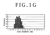
- FIGS. 1A to 1G are graphs showing the influence of the amounts of oleic acid and oleylamine used on the grain diameter of the FePt nanoparticles formed, in terms of the relationship between the diameter of the nanoparticles and the occurrence frequency.
- FIG. 1A shows the grain diameter distribution in the case of where 0.64 mL of oleic acid and 0.68 mL of oleylamine were used, with the average grain diameter being 5.5 nm.
- FIG. 1B shows the grain diameter distribution in the case where 0.32 mL of oleic acid and 0.34 mL of oleylamine were used, with the average grain diameter being 4.3 nm.
- FIG. 1C shows the grain diameter distribution in the case where 0.16 mL of oleic acid and 0.17 mL of oleylamine were used, with the average grain diameter being 3.3 nm.
- FIG. 1D shows the grain diameter distribution in the case where 0.08 mL of oleic acid and 0.08 mL of oleylamine were used, with the average grain diameter being 3.0 nm.
- FIG. 1E shows the grain diameter distribution in the case where 0.04 mL of oleic acid and 0.04 mL of oleylamine were used, with the average grain diameter being 2.6 nm.
- FIG. 1F shows the grain diameter distribution in the case where 0.02 mL of oleic acid and 0.02 mL of oleylamine were used, with the average grain diameter being 2.1 nm.
- FIG. 1G shows the grain diameter distribution in the case where 0.01 mL of oleic acid and 0.01 mL of oleylamine were used, with the average grain diameter being 1.6 nm.
- the average grain diameter of the FePt nanoparticles could be controlled according to the amount of the stabiling ligand added to the reaction liquid. Namely, the amount of the stabilizing ligand used and the average grain diameter of the FePt nanoparticles are roughly in a proportional relationship.
- Example 1 A synthetic reaction was carried out under the same conditions as in Example 1, except that 28.8 mg (0.11 mmol) of bisacetylacetonatocopper was further added to the same reaction liquid as that in Example 1. Regarding the relationship between the amount of the stabilizing ligand used and the grain diameter, the equivalent results to those in Example 1 were obtained.
- the nanoparticles synthesized in this case are FePtCu alloy nanoparticles.
- Example 1 A synthetic reaction was carried out under the same conditions as in Example 1, except that 23.4 mg (0.14 mmol) of silver(I) acetate was further added to the same reaction liquid as that in Example 1. Regarding the relationship between the amount of the stabilizing ligand used and the grain diameter, the equivalent results to those in Example 1 were obtained.
- the nanoparticles synthesized in this case are FePtAg alloy nanoparticles.
- FIG. 2 there is shown a sectional schematic diagram of a perpendicular magnetic recording medium 2A according to a first embodiment of the present invention in which the FePt alloy nanoparticles produced by the method of the present invention are used to form a recording layer.
- a soft magnetic layer 6 composed of FeSi, FeTaC or the like is formed on a substrate 4 such as Al-tempered glass, crystallized glass, etc.
- An intermediate layer 8 composed of carbon, MgO or the like is formed on the soft magnetic layer 6.
- An FePt alloy nanoparticle layer 10 having an average grain diameter of 1 to 3 nm is formed on the intermediate layer 8 by a chemical synthesis method.
- the FePt alloy nanoparticle layer 10 is magnetized in the perpendicular direction, and the FePt alloy nanoparticles 10a are disposed at substantially uniform intervals.
- a carbon protective film 12 is formed on the FePt alloy nanoparticle layer 10, and a lubricant 14 is applied to the carbon protective film 12.
- FIG. 3 there is shown a sectional schematic diagram of a longitudinal magnetic recording medium 2B according to a second embodiment of the present invention in which the FePt alloy nanoparticles are used to form a recording layer.
- a substrate layer 16 composed of NiP or the like is formed on a substrate 4 such as Al-tempered glass, crystallized glass, etc.
- An intermediate layer 18 composed of CrMo or the like is formed on the substrate layer 16.
- An FePt alloy nanoparticle layer 20 magnetized in the longitudinal direction (in-plane direction) is formed on the intermediate layer 18.
- the FePt alloy nanoparticles 20a have an average grain diameter of 1 to 3 nm, and are disposed at substantially uniform intervals.
- a carbon protective film 12 is formed on the FePt alloy nanoparticle layer 20, and a lubricant 14 is applied to the carbon protective layer 12.
- the FePt alloy nanoparticle layer 10 and 20 may be composed of an alloy nanoparticle layer containing Fe, Pt, and an element selected from the group consisting of Ni, Co, Cu, Ag, Mn, and Pb.
- the alloy nanoparticles have an average grain diameter of 2 to 6 nm, preferably 2 to 3 nm, and are disposed at substantially uniform intervals. At the time of annealing, thickening of the grain diameter of the nanoparticles occurs, for the following reason. Where the alloy nanoparticles make contact with each other at a high temperature, mutual fusing of the particles to reduce the specific surface area thereof and to thereby lower the surface energy thereof is advantageous, on an energy basis, to maintaining the independence of the nanoparticles.
- the means is a method in which an organic compound capable of enduring the annealing conditions is mixed into the liquid dispersion of the nanoparticles, and the resultant mixture is applied to a substrate.
- the organic compound dissolved uniformly in the liquid dispersion is capable of evenly filling the voids between the nanoparticles after coating, and the organic compound in the voids is converted into amorphous carbon under appropriate annealing conditions, to impart a high durability to the nanoparticle layer.
- an organic compound suited to the above-mentioned purpose there can be mentioned a combination of a carboxylic acid with an amine functioning as a basic organic compound.
- a carboxylic acid and an amine can be firmly bonded to each other by formation of a salt, resulting in the effect of inhibiting the mutual contact of the nanoparticles.
- the carboxylic acid particularly, oleic acid is preferred since it is excellent as a dispersant for metal particulates.
- the basic organic compound to be used in combination with oleic acid preferred is oleylamine, which has the same molecular main chain length as that of oleic acid and is similar to oleic acid in chemical properties.
- examples of the measure to restrain the mutual fusing of the FePt alloy nanoparticles include the following methods.
- the density of the FePt nanoparticles in the nanoparticle layer must be not less than a certain level.
- the proportion of the number of carbon atoms is preferably in the range of from 50 at%, inclusive, to 85 at%, exclusive.
- a coating liquid was used which was obtained by dispersing FePt alloy nanoparticles, a carboxylic acid, and an amine in hexane.
- the organic solvent heptane or octane may be used in place of hexane.
- FIG. 4 shows a general schematic diagram of the spin coating apparatus in an opened condition, wherein the basis structure is composed of a hermetic sealing cup 28 through which a disk substrate rotating mechanism 26 for holding and rotating a disk substrate 24 is passed, and a hermetic sealing plate 34 through which a coating liquid syringe 30 and a hexane syringe 32 are passed.
- a cup vertical movement mechanism 36 for forming a hermetically sealed space by vertically moving the hermetic sealing cup 28 and bringing it into contact with the hermetic sealing plate 34 is provided.
- one of the contact portions of the hermetic sealing cup 28 and the hermetic sealing plate 34 is provided with gas-tight sealing means such as an O-ring.
- An oil-free pump 38 for evacuating the hermetically sealed space to a vacuum is connected to the hermetic sealing cup 28 through a piping.
- a Pirani gage 40 for measuring the degree of vacuum in the hermetically sealed space and a hexane vapor pressure sensor 42 for measuring the vapor pressure of hexane introduced as a solvent are disposed in the hermetic sealing cup 28.
- the coating liquid syringe 30 is fitted with a controller 31 for controlling the dropping amount of the coating liquid. Further, the coating liquid syringe 30 is provided with a mechanism for rectilinearly moving the coating liquid syringe 30 in the radial direction of the substrate 24 while maintaining the gas-tight structure.
- the hexane syringe 32 is provided with a mass flow controller 33 for controlling the amount of hexane introduced, and a hot plate 44 is disposed on the lower side of the hexane syringe 32. The hexane dropped is evaporated by being heated by the hot plate 44, to fill the hermetically sealed space with a hexane atmosphere.
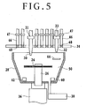
- FIG. 5 shows a general schematic diagram of the spin coating apparatus in a hermetically sealed condition, wherein a hermetically sealed film forming chamber 50 can be formed by vertically moving the hermetic sealing cup 28 by the cup vertical movement mechanism 36 to bring the hermetic sealing cup 28 into contact with the hermetic sealing plate 34.
- the disk substrate 24 consisting of an annular silicon substrate having an outside diameter of 65 mm and an inside diameter of 20 mm was fixed to the disk substrate rotating mechanism 26 by vacuum suction, and the disk substrate 24 was rotated at 300 rpm.
- the cup vertical movement mechanism 36 was driven to move the hermetic sealing cup 28 upwards, and to bring the hermetic sealing cup 28 into contact with the hermetic sealing plate 34, thereby forming the hermetically sealed film forming chamber 50, as shown in FIG. 5.
- Hexane in an amount of 100 mL, was introduced from the hexane syringe 32 into the hermetically sealed film forming chamber 50, and the hot plate 44 was heated to about 80°C to evaporate hexane, thereby preliminarily providing a hexane atmosphere in the hermetically sealed film forming chamber 50.
- 200 ⁇ L of a coating liquid prepared by dispersing FePt nanoparticles and an organic compound containing a carboxylic acid and an amine in hexane used as a solvent was dropped from the coating liquid syringe 30 over a period of 5 sec.
- the dropping of the coating liquid was conducted while moving the coating liquid syringe 30 at a velocity of 0.5 cm/sec in the radial direction indicated by an arrow in FIG. 6 under the condition where the disk substrate 24 is rotated at a low speed of 60 rpm, as shown in FIG. 6.
- the coating liquid 52 was dropped in a volute pattern relative to the disk substrate 24.
- the disk substrate 24 was rotated at 1000 rpm for 10 sec, to spread the coating liquid 52 over the entire surface of the disk substrate 24.
- the hermetically sealed film forming chamber 50 is filled with the hexane vapor, so that hexane contained in the coating liquid 52 would not be evaporated.
- N 2 gas was introduced via the gas inlet pipes 46 and the conductance valves 48 into the hermetically sealed film forming chamber 50 at a flow rate of 10 sccm for 120 sec, in the condition where the disk substrate 24 is rotated at 300 rpm, to thereby evaporate the hexane contained in the coating liquid 52.
- the N 2 gas collides uniformly on the entire surface of the disk substrate 24, and the evaporation of hexane occurs slowly and uniformly on the entire surface of the disk substrate 24, so that it is possible to form a nanoparticle layer in which the FePt alloy nanoparticles are aligned orderly and in a uniform thickness.
- FIGS. 7A to 7C show the surface conditions of the film after annealed, according to the lapse of time.
- FIG. 7A shows the surface condition of the film before annealed
- FIG. 7B shows the surface condition of the film annealed on the 17th day after film formation
- FIG. 7C shows the surface condition of the film annealed on the 59th day after film formation.
- the annealing was carried out by holding at 550°C and 1 ⁇ 10 4 Pa for 30 min.
- the composition of the nanoparticles was Fe 53 Pt 47 .
- the nanoparticles annealed after 17 days, shown in FIG. 7B show the thickening and aggregation of the particles.
- the nanoparticles annealed after 59 days shown in FIG. 7C, show no thickening and no aggregation of the particles.
- the film formation of an FePt alloy nanoparticle layer was conducted in the same conditions as in Example 4.
- a carbon protective film with a film thickness of 5 nm was formed on the nanoparticle layer by a sputtering method. Specifically, a sample was set in a chamber, the film forming chamber was evacuated to 10 -5 Pa, then Ar was introduced to a pressure of 0.5 Pa, and DC discharge at 400 W was conducted, to form the carbon protective film to the thickness of 5 nm.
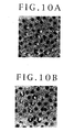
- FIG. 10A is a TEM photograph of the sample with carbon cap before annealed
- FIG. 10B is a TEM photograph of the sample with carbon cap after annealed with electron beams for 1 hr
- FIG. 11A is a TEM photograph of the sample without carbon cap before annealed
- FIG. 11B is a TEM photograph of the sample without carbon cap after annealed with electron beams for 1 hr.
- the nanoparticles were annealed with the electron beams, and were thereby thickened and aggregated.
- the sample with carbon cap no aggregation of the nanoparticles occurred, as shown in FIG. 10B. While the carbon cap was formed on the nanoparticle layer in this example, the same effect can be expected also when a carbon substrate layer is formed on the substrate and the nanoparticle layer is formed on the carbon substrate layer.
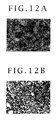
- FIG. 12A shows a TEM photograph of the surface of the thin film
- FIG. 12B shows a TEM photograph of the surface of the thick film.
- the nanoparticles were aggregated and thickened, while in the thin film shown in FIG. 12A, no aggregation of the nanoparticles occurred.
- the same type of experiments were conducted by preparing various samples while changing the film thickness. As a result of the experiments, it was found out that aggregation of the nanoparticles does not occur when the film thickness is 80 nm or below.
- the film thickness of the nanoparticle layer is in the range of 5 to 20 nm.
- the film formation of an FePt alloy nanoparticle layer was conducted in the same conditions as in Example 4. In this example, suppression of aggregation of the nanoparticles while obtaining a high coercive force will be described.
- Thin film samples were annealed for 30 min in a vacuum at temperatures of 600, 650, 700, 750, 800, 850, and 900°C, respectively.
- FIG. 13 shows the relationship between annealing temperature and coercive force. In the thin film samples, the coercive force is saturated at an annealing temperature of 850°C, reaching 6 kOe.
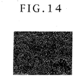
- the surface condition of the thin film annealed at 800°C is shown in FIG. 14. It is clear from FIG. 14 that the nanoparticles were not aggregated.
- the coercive force of the sample free of aggregation is not more than one half of the coercive force of the sample in which the nanoparticles have been aggregated; this is the result of the thermal fluctuation phenomenon occurring due to the small size of the nanoparticles.
- the nanoparticles are influenced by thermal fluctuation because of their small grain diameter, with the result that the temperature variation of coercive force is steep.
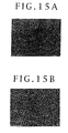
- FIG. 15A shows the surface condition after the baking. Further, vacuum annealing was conducted at 800°C for 30 min. The surface condition after the annealing is shown in FIG. 15B. It is seen that the nanoparticles were not aggregated but remained separate from each other even upon the 800°C annealing, since the salt had been formed by the above-mentioned baking treatment.
- FIG. 16 there is shown a schematic diagram of a perpendicular magnetic recording medium according to a third embodiment of the present invention in which the above-mentioned FePt alloy nanoparticle layer is adopted as a recording layer. Substantially the same components as those in the recording media in the first and second embodiments are denoted by the same symbols as used above.
- An orientation control layer 5 for a soft magnetic layer 6 is formed on a substrate 4, and the soft magnetic layer 6 is formed on the orientation control layer 5.
- An intermediate layer 8 is formed on the soft magnetic layer 6, and a nanoparticle magnetic layer 54 is formed on the intermediate layer 8.
- the nanoparticle magnetic layer 54 contains FePt alloy nanoparticles 54a having an average diameter of 2 to 10 nm, and amorphous carbon filling the voids between the nanoparticles 54a.
- the FePt alloy nanoparticles 54a are disposed at substantially uniform intervals.
- the nanoparticle magnetic layer 54 is magnetized in the perpendicular direction.
- a carbon protective film 12 is formed on the nanoparticle magnetic layer 54, and a lubricant 14 is applied to the carbon protective layer 12.
- FIG. 17 shows a schematic diagram of a longitudinal magnetic recording medium according to a fourth embodiment of the present invention in which an FePt alloy nanoparticle layer is adopted as a recording layer. Substantially the same components as those in the first to third embodiments are denoted by the same symbols as used above.
- a substrate layer 16 composed of NiP or the like is formed on a substrate 4, and an intermediate layer 18 is formed on the substrate layer 16.
- a nanoparticle magnetic layer 56 is formed on the intermediate layer 18.
- the nanoparticle magnetic layer 56 contains FePt alloy nanoparticles 56a having an average diameter of 2 to 10 nm, and amorphous carbon filling the voids between the nanoparticles 56a.
- the FePt alloy nanoparticles 56a are disposed at substantially uniform intervals.
- the nanoparticle magnetic layer 56 is magnetized in the longitudinal direction (in-plane direction).
- a carbon protective film 12 is formed on the nanoparticle magnetic layer 56, and a lubricant 14 is applied to the carbon protective layer 12.
- FIG. 18 there is shown a schematic diagram of a perpendicular magnetic recording medium according to a fifth embodiment of the present invention.
- a soft magnetic layer 6 formed of FeTaC or the like is formed on a substrate 4, and a carbon intermediate layer 8' is formed on the soft magnetic layer 6.
- the film thickness of the soft magnetic layer 6 is 200 nm, while the film thickness of the carbon intermediate layer 8' is 5 nm, and both were formed by a sputtering method.
- the film thickness of the carbon intermediate layer 8' is preferably in the range of 1 to 10 nm.
- a magnetic nanoparticle layer 58 is formed on the carbon intermediate layer 8'.
- the magnetic nanoparticle layer 58 is formed by a chemical synthesis method, in the same manner as in the above-described embodiments.
- the magnetic nanoparticle layer 58 contains a plurality of mutually separated nanoparticles 58a having a grain diameter variance of not more than 10%.
- the magnetic nanoparticles 58a in the magnetic nanoparticle layer 58 have an average grain diameter of 2 to 10 nm, and the inter-grain interval is in the range of 0.2 to 5 nm.
- the magnetic nanoparticles 58a contain at least two elements selected from the group consisting of Fe, Pt, Ni, Co, Cu, Ag, Mn, and Pb.
- the magnetic nanoparticles 58a consist of FePt nanoparticles.
- the magnetic nanoparticle layer 58 further contains a stabilizing ligand (stabilizer) which fills the voids between the magnetic nanoparticles 58a and which is selected from the group consisting of carboxylic acids, sulfonic acids, sulfinic acids, phosphonic acids, and amines.
- a carbon protective film 12 is formed on the magnetic nanoparticle layer 58 by a sputtering method.
- the carbon protective film 12 has a film thickness of 1 to 5 nm; in this embodiment, the film thickness was 5 nm.
- a sample with the magnetic nanoparticle layer 58 sandwiched between the carbon intermediate layer 8' and the carbon protective film 12 was placed in an annealing chamber, the chamber was evacuated to a vacuum of 3 ⁇ 10 -5 Pa, the temperature was raised to 800°C over a period of 10 min, the temperature of 800°C was maintained for 30 min, then the temperature was lowered to room temperature, and the sample was taken out. Thereafter, a lubricant 14 was applied to the carbon protective film 12.
- FIG. 19A shows a TEM image of the nanoparticle layer before annealed.
- FIG. 19B shows a TEM image of the nanoparticles after annealed.
- FIG. 20 shows a TEM image of a nanoparticle layer after annealed, of a medium provided with neither the intermediate layer 8' nor the carbon protective film 12.
- FIG. 19B in the case where the carbon intermediate layer 8' and the carbon protective film 12 are present, mutual fusing of the nanoparticles is not observed even upon annealing.
- the nanoparticles are found to have grown larger through mutual fusing.
- Table 2 shows the average grain diameter D, the standard deviation ⁇ of grain diameter, and grain diameter variance ⁇ /D, before and after annealing.
- the grain diameter variance is slightly larger after the annealing, the average grain diameter D is not changed by the annealing. This can be interpreted that movement of the nanoparticles was restrained by the carbon intermediate layer 8' and the carbon protective film 12 and, therefore, the mutual fusing of the nanoparticles was prevented.
- a medium provided with neither the carbon intermediate layer 8' nor the carbon protective film 12 and a medium provided with a 5 nm thick carbon intermediate layer 8' but not provided with the carbon protective film were prepared. These medium samples were placed in an annealing chamber, the chamber was evacuated to a vacuum of 3 ⁇ 10 -5 Pa, the temperature was raised to 800°C over a period of 10 min, the temperature of 800°C was maintained for 30 min, then the temperature was lowered to room temperature, and the medium samples were taken out.
- Table 3 shows the average grain diameters D, the standard deviations ⁇ of grain diameter, and the grain diameter variances ⁇ /D, in the case where the carbon intermediate layer is present and in the case where the carbon intermediate layer is absent.
- the amount of the stabilizing ligand was set to be half the ordinary amount, and, as a result, the growth of the nanoparticles to greater particles is made to be conspicuous.
- the average grain diameter is smaller, and the mutual fusing of the nanoparticles is suppressed, as compared with the case of the medium without the carbon intermediate layer.
- the present invention it is possible to control the grain diameter of nanoparticles and to realize a reduction in the noises in a magnetic recording medium. Besides, it is possible to obtain a high coercive force while preventing the aggregation and thickening of the nanoparticles. As a result, it is possible to produce a superhigh-density magnetic recording medium.
Landscapes
- Chemical & Material Sciences (AREA)
- Engineering & Computer Science (AREA)
- Nanotechnology (AREA)
- Inorganic Chemistry (AREA)
- Metallurgy (AREA)
- General Chemical & Material Sciences (AREA)
- Crystallography & Structural Chemistry (AREA)
- Chemical Kinetics & Catalysis (AREA)
- Condensed Matter Physics & Semiconductors (AREA)
- Materials Engineering (AREA)
- General Health & Medical Sciences (AREA)
- Molecular Biology (AREA)
- Power Engineering (AREA)
- Physics & Mathematics (AREA)
- Composite Materials (AREA)
- Life Sciences & Earth Sciences (AREA)
- General Physics & Mathematics (AREA)
- Biomedical Technology (AREA)
- Health & Medical Sciences (AREA)
- Dispersion Chemistry (AREA)
- Ceramic Engineering (AREA)
- Manufacturing Of Magnetic Record Carriers (AREA)
- Manufacture Of Metal Powder And Suspensions Thereof (AREA)
- Magnetic Record Carriers (AREA)
- Hard Magnetic Materials (AREA)
- Powder Metallurgy (AREA)
Abstract
A method of producing alloy nanoparticles includes
the steps of: adding a metallic salt, a reducing agent, a
stabilizing ligand, and an organic iron complex to an
organic solvent selected from the group consisting of 2-20C
hydrocarbon, alcohol, ether, and ester in an inert
gas atmosphere to obtain a reaction liquid; and stirring
the reaction liquid while heating the reaction liquid to
a predetermined temperature. The grain diameter of the
alloy nanoparticle is controlled by regulating the amount
of the stabilizing ligand.
Description
The present invention relates to alloy
nanoparticles, a method of producing the same, and a
magnetic recording medium using the alloy nanoparticles.
For enhancing the recording density of a magnetic
recording medium, it is necessary to render the magnetic
clusters of the medium smaller and more uniform and to
weaken the magnetic coupling between the adjacent
magnetic clusters. For this purpose, it is necessary to
reduce and uniformize the crystal grain diameters of the
magnetic metal forming the recording layer of the medium
and to cover the gaps between the adjacent crystal grains
with a nonmagnetic metal. However, where the crystal
grain diameter is reduced, the problem called "thermal
fluctuation" in which spontaneous magnetization is
gradually lost becomes also conspicuous. To cope with
these problems, various inventions and improvements have
hitherto been made.
As one of the methods for obtaining a magnetic
metal in the form of nanometer scale crystals with
uniform grain diameters, a chemical synthesis method has
been proposed (Science, vol. 287, p. 1989, and Japanese
Patent Laid-open No. 2000-48340). The technology consists
in chemically synthesizing an FePt alloy having a high
magnetic anisotropy and highly resistant to thermal
fluctuation. According to this technology, FePt crystal
grains are naturally and orderly aligned with the
adjacent crystal grains through an organic compound as a
medium, which is called "self-assembling", and the
crystal grains have grain diameters of about 4 nm and are
excellent in dispersion; therefore, the FePt alloy
according to this technology is expected as a recording
medium of a superhigh-density recording medium.
However, for continued enhancement of the
performance of magnetic recording media, a technology for
controlling the grain diameter of a magnetic metal is
needed, but it has been impossible to freely control the
grain diameter in the case of the magnetic alloy
nanoparticles obtained by the above-mentioned chemical
synthesis method. For example, in the case of FePt
nanoparticles, only the conditions for obtaining
particles with a grain diameter of 3 to 4 nm have been
known. Therefore, in order to obtain nanoparticles with a
different grain diameter, it has been necessary to add
the raw material to a liquid dispersion of the once
synthesized nanoparticles, and to perform the reaction
again, thereby growing the particles. By this method,
naturally, it is impossible to obtain particles with
grain diameters smaller than the grain diameter of 3 to 4
nm of the particles initially synthesized.
The FePt alloy displays magnetism by the change of
the fcc crystal structure to the fct structure through
ordering. The ordering needs annealing; annealing of a
substrate coated with FePt makes it possible for FePt to
acquire a high coercive force. In general, there is a
correlation between the annealing temperature and the
coercive force, and the coercive force increases with a
rise in the annealing temperature (Science, vol. 287, p.
1989). It has been reported, however, that annealing at a
high temperature causes bonding between the adjacent
nanoparticles, resulting in the formation of crystals
greater in grain diameter (Applied Physics Letters, vol.
79, No. 26, p. 4393). When the grain diameter is enlarged
by the bonding between crystal grains, the average grain
diameter of the crystal grains is enlarged, and the
variance of the grain diameter is also enlarged, with the
result that the advantage of nanoparticles is lost.
Accordingly, it is an object of the present
invention to provide a method of producing alloy
nanoparticles by which it is possible to arbitrarily
control the grain diameter of the alloy nanoparticles
being synthesized.
It is another object of the present invention to
provide a magnetic recording medium in which alloy
nanoparticles are applied to a recording medium without
increasing the grain diameter of alloy nanoparticles or
the variance of grain diameter.
In accordance with one aspect of the present
invention, there are provided FePt alloy nanoparticles
having an average diameter in the range of 1 to 3 nm. In
addition to Fe and Pt, the FePt alloy nanoparticles may
contain an element selected from the group consisting of
Ni, Co, Cu, Ag, Mn, and Pb.
In accordance with another aspect of the present
invention, there is provided a method of producing alloy
nanoparticles, including the steps of: adding a metallic
salt, a reducing agent, a stabilizing ligand, and an
organic iron complex to an organic solvent selected from
the group consisting of 2-20C hydrocarbon, alcohol, ether,
and ester in an inert gas atmosphere to obtain a reaction
liquid; and stirring the reaction liquid while heating
the liquid to a predetermined temperature, wherein the
grain diameter of the alloy nanoparticles is controlled
by the amount of the stabilizing ligand.
The stabilizing ligand is selected from the group
consisting of carboxylic acid, sulfonic acid, sulfinic
acid, phosphonic acid, and amine. Preferably, the organic
iron complex is selected from the group consisting of
Fe(CO)5, Fe2(CO)9, and Fe3(CO)12. Preferably, the metallic
salt is selected from the group consisting of
bisacetylacetonatoplatinum, bisbenzonitrileplatinum
dichloride, platinum(II) bromide, platinum(II) chloride,
and platinum(II) iodide.
In accordance with a further aspect of the present
invention, there is provided a magnetic recording medium
including: a substrate; an FePt alloy nanoparticle layer
containing FePt alloy nanoparticles which are disposed at
substantially uniform intervals on the substrate and have
an average diameter of 1 to 3 nm; and a protective film
formed on the FePt alloy nanoparticle layer.
In accordance with yet another aspect of the
present invention, there is provided a magnetic recording
medium including: a substrate; a nanoparticle magnetic
layer containing FePt alloy nanoparticles which are
disposed at substantially uniform intervals on the
substrate, and have an average diameter of 2 to 10 nm,
and a carbon phase filling the voids between the FePt
alloy nanoparticles; and a protective film formed on the
nanoparticle magnetic layer, wherein the proportion of
the number of carbon atoms contained in the carbon phase
based on the sum of the number of metallic atoms
constituting the FePt alloy nanoparticles and the number
of the carbon atoms is in the range of from 50 at%,
inclusive, to 85 at%, exclusive.
In accordance with a yet further aspect of the
present invention, there is provided a method of
manufacturing a magnetic recording medium, including the
steps of: dispersing FePt alloy nanoparticles and an
organic mixture containing a carboxylic acid and an amine
in a solvent selected from the group consisting of hexane,
heptane, and octane, to obtain a coating liquid; applying
the coating liquid to a substrate; drying the coating
liquid to form, on the substrate, a magnetic nanoparticle
layer comprised of the FePt alloy nanoparticles and the
organic mixture filling the voids between the FePt alloy
nanoparticles; permitting a salt to be formed between the
carboxylic acid and the amine; and annealing the magnetic
nanoparticle layer.
The step of permitting a salt between the
carboxylic acid and the amine is composed of the step of
maintaining the magnetic nanoparticle layer in N2 gas for
not less than 5 days, or is composed of the step of
subjecting the magnetic nanoparticle layer to a baking
treatment at a temperature of not lower than the boiling
point of the solvent for a period of 5 to 60 min, or is
composed of the step of maintaining the magnetic
nanoparticle layer in a vacuum for not less than 1 hr.
In accordance with still another aspect of the
present invention, there is provided a method of
manufacturing a magnetic recording medium, including the
steps of: dispersing FePt alloy nanoparticles and an
organic mixture containing a carboxylic acid and an amine
in a solvent selected from the group consisting of hexane,
heptane, and octane, to obtain a coating liquid; applying
the coating liquid to a substrate; drying the coating
liquid to form, on the substrate, a magnetic nanoparticle
layer comprised of the FePt alloy nanoparticles and the
organic mixture filling the voids between the FePt alloy
nanoparticles; forming a carbon cap on the magnetic
nanoparticle layer; and annealing the magnetic
nanoparticle layer. A carbon substrate layer may be
formed on the substrate, instead of forming the carbon
cap on the magnetic nanoparticle layer.
In accordance with a still further aspect of the
present invention, there is provided a magnetic recording
medium including: a substrate; a carbon layer formed on
the substrate; a magnetic nanoparticle layer formed on
the carbon layer and having an average grain diameter in
the range of 2 to 10 nm and an inter-grain interval in
the range of 0.2 to 5 nm; and a carbon protective film
formed on the magnetic nanoparticle layer, wherein the
magnetic nanoparticle layer is comprised of a plurality
of mutually separated nanoparticles having a grain
diameter variance of not more than 10%.
Preferably, the film thickness of the carbon layer
is in the range of 1 to 10 nm, and the film thickness of
the carbon protective film is in the range of 1 to 5 nm.
The present invention is based on the finding that,
in chemical synthesis of nanoparticles using a reaction
liquid, the size of the nanoparticles can be controlled
by regulating the saturation concentration of a metal in
the reaction liquid. In the synthesis of nanoparticles,
as the reaction proceeds, the amount of the metal for
constituting the nanoparticles increases in the reaction
liquid, and the alloy nanoparticles starts being formed
when the concentration of the metal has exceeded its
saturation concentration. In this case, if the saturation
concentration of the metal in the reaction liquid is high,
it is difficult for aggregates of the metal atoms
functioning as nuclei of the nanoparticles to be formed,
with the result that the number of the aggregates is
small and, therefore, the individual nanoparticles grow
to large sizes. On the contrary, in a reaction liquid in
which the saturation concentration of the metal is low,
the nanoparticles formed are small in grain diameter.
The saturation concentration of the metal in the
reaction liquid can be varied by varying the amount of a
stabilizing ligand (stabilizer) used in the synthesis
reaction. In organic solvents such as ethers, alcohols,
esters and hydrocarbons, the saturation concentration of
a metal is extremely low. Therefore, the saturation
concentration of the metal in the reaction liquid depends
not on the concentration but on the absolute amount, of
the stabilizing ligand in the reaction liquid.
Accordingly, the present invention is characterized in
that the grain diameter of nanoparticles is controlled by
the absolute amount of the stabilizing ligand used.
According to one embodiment of the present
invention, there is provided a method of producing alloy
nanoparticles. The method of producing alloy
nanoparticles includes the steps of: adding a metallic
salt, a reducing agent, a stabilizing ligand, and an
organic iron complex to an organic solvent selected from
the group consisting of 2-20C hydrocarbon, alcohol, ether,
and ester to obtain a reaction liquid; and stirring the
reaction liquid while heating the reaction liquid to a
predetermined temperature. Further, the method is
characterized in that the grain diameter of the alloy
nanoparticles is controlled by the amount of the
stabilizing ligand. Examples of the stabilizing ligand
which can be used include 6-22C carboxylic acids,
sulfonic acids, sulfinic acids, and phosphonic acids.
Further examples of the stabilizing ligand include basic
organic compounds such as 6-22C amines.
Particularly preferred examples are oleic acid,
which is one of the carboxylic acids having a high
ability to disperse metal particulates in the liquid, and
oleylamine which has the same carbon chain as that of
oleic acid and is similar to oleic acid in chemical
properties. The acid and the amine may be used singly or
may simultaneously be used in combination. The
combination of oleic acid and oleylamine is particularly
preferable. The heating temperature for the reaction
liquid is preferably in the range of 220 to 260°C. The
organic iron complex is preferably Fe(CO)5, Fe2(CO)9, or
Fe3(CO)12. The metallic salt may be bisacetylacetonatoplatinum,
bisbenzonitrileplatinum dichloride,
platinum(II) bromide, platinum(II) chloride, or
platinum(II) iodide.
Now, the present invention will be described below,
based on specific examples.
In an argon gas atmosphere, 20 mL of dioctyl ether
was added to a flask charged with 197 mg (0.5 mmol) of
bisacetylacetonatoplatinum and 390 mg of 1,2-hexadecanediol.
Further, 0.32 mL (1.0 mmol) of oleic acid
and 0.34 mL (1.0 mmol) of oleylamine were added to the
mixture, and then 0.13 mL (1.0 mmol) of Fe(CO)5 was added
to the mixture, to obtain a reaction liquid.
After the reaction liquid was brought into reaction
by stirring it at 230°C for 30 min, the reaction mixture
was allowed to cool to room temperature, and 40 mL of
ethanol was added to the reaction mixture, followed by
centrifugation. Further, the precipitate was dispersed in
hexane, to obtain a dispersion of FePt alloy
nanoparticles. The FePt alloy nanoparticles obtained
under these conditions had an average grain diameter of
4.3 nm. The grain diameter of the FePt alloy
nanoparticles can be controlled by varying the amounts of
oleic acid and oleylamine used in the above-mentioned
synthetic reaction. The variation in the grain diameter
of the FePt alloy nanoparticles obtained by varying only
the amounts of oleic acid and oleylamine, among the
above-mentioned reaction conditions, is shown in Table 1
and in FIGS. 1A to 1G.
| Amount of oleic acid used | Amount of oleylamine used | Average grain diameter of FePt nanoparticles | Variance of grain diameter |
| 0.01 mL | 0.01 mL | 1.6 nm | 19% |
| 0.02 mL | 0.02 mL | 2.1 nm | 17% |
| 0.04 mL | 0.04 mL | 2.6 | 18% |
| 0.08 mL | 0.08 mL | 3.0 nm | 11% |
| 0.16 mL | 0.17 mL | 3.3 | 10% |
| 0.32 mL | 0.34 mL | 4.3 | 12% |
| 0.64 mL | 0.68 mL | 5.5 | 8% |
FIGS. 1A to 1G are graphs showing the influence of
the amounts of oleic acid and oleylamine used on the
grain diameter of the FePt nanoparticles formed, in terms
of the relationship between the diameter of the
nanoparticles and the occurrence frequency. FIG. 1A shows
the grain diameter distribution in the case of where 0.64
mL of oleic acid and 0.68 mL of oleylamine were used,
with the average grain diameter being 5.5 nm. FIG. 1B
shows the grain diameter distribution in the case where
0.32 mL of oleic acid and 0.34 mL of oleylamine were used,
with the average grain diameter being 4.3 nm. FIG. 1C
shows the grain diameter distribution in the case where
0.16 mL of oleic acid and 0.17 mL of oleylamine were used,
with the average grain diameter being 3.3 nm.
FIG. 1D shows the grain diameter distribution in
the case where 0.08 mL of oleic acid and 0.08 mL of
oleylamine were used, with the average grain diameter
being 3.0 nm. FIG. 1E shows the grain diameter
distribution in the case where 0.04 mL of oleic acid and
0.04 mL of oleylamine were used, with the average grain
diameter being 2.6 nm. FIG. 1F shows the grain diameter
distribution in the case where 0.02 mL of oleic acid and
0.02 mL of oleylamine were used, with the average grain
diameter being 2.1 nm. FIG. 1G shows the grain diameter
distribution in the case where 0.01 mL of oleic acid and
0.01 mL of oleylamine were used, with the average grain
diameter being 1.6 nm.
As is clear from Table 1 and FIGS. 1A to 1G, the
average grain diameter of the FePt nanoparticles could be
controlled according to the amount of the stabiling
ligand added to the reaction liquid. Namely, the amount
of the stabilizing ligand used and the average grain
diameter of the FePt nanoparticles are roughly in a
proportional relationship.
A synthetic reaction was carried out under the same
conditions as in Example 1, except that 28.8 mg (0.11
mmol) of bisacetylacetonatocopper was further added to
the same reaction liquid as that in Example 1. Regarding
the relationship between the amount of the stabilizing
ligand used and the grain diameter, the equivalent
results to those in Example 1 were obtained. The
nanoparticles synthesized in this case are FePtCu alloy
nanoparticles.
A synthetic reaction was carried out under the same
conditions as in Example 1, except that 23.4 mg (0.14
mmol) of silver(I) acetate was further added to the same
reaction liquid as that in Example 1. Regarding the
relationship between the amount of the stabilizing ligand
used and the grain diameter, the equivalent results to
those in Example 1 were obtained. The nanoparticles
synthesized in this case are FePtAg alloy nanoparticles.
Referring to FIG. 2, there is shown a sectional
schematic diagram of a perpendicular magnetic recording
medium 2A according to a first embodiment of the present
invention in which the FePt alloy nanoparticles produced
by the method of the present invention are used to form a
recording layer. A soft magnetic layer 6 composed of FeSi,
FeTaC or the like is formed on a substrate 4 such as Al-tempered
glass, crystallized glass, etc. An intermediate
layer 8 composed of carbon, MgO or the like is formed on
the soft magnetic layer 6.
An FePt alloy nanoparticle layer 10 having an
average grain diameter of 1 to 3 nm is formed on the
intermediate layer 8 by a chemical synthesis method. The
FePt alloy nanoparticle layer 10 is magnetized in the
perpendicular direction, and the FePt alloy nanoparticles
10a are disposed at substantially uniform intervals. A
carbon protective film 12 is formed on the FePt alloy
nanoparticle layer 10, and a lubricant 14 is applied to
the carbon protective film 12.
Referring to FIG. 3, there is shown a sectional
schematic diagram of a longitudinal magnetic recording
medium 2B according to a second embodiment of the present
invention in which the FePt alloy nanoparticles are used
to form a recording layer. A substrate layer 16 composed
of NiP or the like is formed on a substrate 4 such as Al-tempered
glass, crystallized glass, etc. An intermediate
layer 18 composed of CrMo or the like is formed on the
substrate layer 16. An FePt alloy nanoparticle layer 20
magnetized in the longitudinal direction (in-plane
direction) is formed on the intermediate layer 18. The
FePt alloy nanoparticles 20a have an average grain
diameter of 1 to 3 nm, and are disposed at substantially
uniform intervals. A carbon protective film 12 is formed
on the FePt alloy nanoparticle layer 20, and a lubricant
14 is applied to the carbon protective layer 12.
In the first and second embodiments shown in FIGS.
2 and 3, the FePt alloy nanoparticle layer 10 and 20 may
be composed of an alloy nanoparticle layer containing Fe,
Pt, and an element selected from the group consisting of
Ni, Co, Cu, Ag, Mn, and Pb. In this case, the alloy
nanoparticles have an average grain diameter of 2 to 6 nm,
preferably 2 to 3 nm, and are disposed at substantially
uniform intervals. At the time of annealing, thickening
of the grain diameter of the nanoparticles occurs, for
the following reason. Where the alloy nanoparticles make
contact with each other at a high temperature, mutual
fusing of the particles to reduce the specific surface
area thereof and to thereby lower the surface energy
thereof is advantageous, on an energy basis, to
maintaining the independence of the nanoparticles.
Therefore, in order to maintain the independent
condition of the nanoparticles, means for inhibiting the
mutual contact of the nanoparticles is needed. One
example of the means is a method in which an organic
compound capable of enduring the annealing conditions is
mixed into the liquid dispersion of the nanoparticles,
and the resultant mixture is applied to a substrate. The
organic compound dissolved uniformly in the liquid
dispersion is capable of evenly filling the voids between
the nanoparticles after coating, and the organic compound
in the voids is converted into amorphous carbon under
appropriate annealing conditions, to impart a high
durability to the nanoparticle layer.
As an organic compound suited to the above-mentioned
purpose, there can be mentioned a combination
of a carboxylic acid with an amine functioning as a basic
organic compound. A carboxylic acid and an amine can be
firmly bonded to each other by formation of a salt,
resulting in the effect of inhibiting the mutual contact
of the nanoparticles. As the carboxylic acid,
particularly, oleic acid is preferred since it is
excellent as a dispersant for metal particulates. As the
basic organic compound to be used in combination with
oleic acid, preferred is oleylamine, which has the same
molecular main chain length as that of oleic acid and is
similar to oleic acid in chemical properties.
By combining oleic acid and oleylamine, which have
high affinity to each other, it is possible to make
uniform the mixed condition of the organic compound in
the gaps between the nanoparticles while stably
dispersing the alloy nanoparticles. It should be noted
here that in the case of a nanoparticle medium, the FePt
alloy nanoparticles as well as the carboxylic acid and
the amine are dissolved in an organic solvent such as
hexane, heptane, and octane and the solution is applied
to a substrate; in this case, the proportions of the
carboxylic acid and the amine that are forming the salt
immediately upon the coating, based on the total amounts
of the carboxylic acid and the amine, are low. In view of
this, various method have been investigated for achieving
effective formation of the salt between the carboxylic
acid and the amine. As a result of the investigation, it
has been found that the following methods are effective.
Other than the above, examples of the measure to
restrain the mutual fusing of the FePt alloy
nanoparticles include the following methods.
In addition, a method of physically restraining the
FePt alloy nanoparticles from moving has been confirmed
to be effective to a certain extent. Examples of this
method include the following ones.
Besides, investigations have been conducted by
variously changing the ratio between the amount of the
FePt alloy nanoparticles and the amount of the organic
compound containing the carboxylic acid and the amine. As
a result of the investigations, it has been found out
that, when the proportion of the number of carbon atoms
filling the voids between the FePt nanoparticles in the
nanoparticle layer containing the FePt alloy
nanoparticles after annealing based on the sum of the
number of metal atoms constituting the nanoparticles and
the number of the carbon atoms is not less than 50 atm%,
a high effect of restraining the mutual fusing of the
FePt nanoparticles is obtained. On the other hand, on a
magnetic characteristic basis, the density of the FePt
nanoparticles in the nanoparticle layer must be not less
than a certain level. In view of the above, the
proportion of the number of carbon atoms is preferably in
the range of from 50 at%, inclusive, to 85 at%, exclusive.
For forming the magnetic metal, a coating liquid
was used which was obtained by dispersing FePt alloy
nanoparticles, a carboxylic acid, and an amine in hexane.
As the organic solvent, heptane or octane may be used in
place of hexane. The formation of the nanoparticle layer
on a substrate was conducted by use of a spin coating
apparatus as shown in FIG. 4. FIG. 4 shows a general
schematic diagram of the spin coating apparatus in an
opened condition, wherein the basis structure is composed
of a hermetic sealing cup 28 through which a disk
substrate rotating mechanism 26 for holding and rotating
a disk substrate 24 is passed, and a hermetic sealing
plate 34 through which a coating liquid syringe 30 and a
hexane syringe 32 are passed.
At a bottom portion of the hermetic sealing cup 28,
a cup vertical movement mechanism 36 for forming a
hermetically sealed space by vertically moving the
hermetic sealing cup 28 and bringing it into contact with
the hermetic sealing plate 34 is provided. Incidentally,
one of the contact portions of the hermetic sealing cup
28 and the hermetic sealing plate 34 is provided with
gas-tight sealing means such as an O-ring. An oil-free
pump 38 for evacuating the hermetically sealed space to a
vacuum is connected to the hermetic sealing cup 28
through a piping. A Pirani gage 40 for measuring the
degree of vacuum in the hermetically sealed space and a
hexane vapor pressure sensor 42 for measuring the vapor
pressure of hexane introduced as a solvent are disposed
in the hermetic sealing cup 28.
The coating liquid syringe 30 is fitted with a
controller 31 for controlling the dropping amount of the
coating liquid. Further, the coating liquid syringe 30 is
provided with a mechanism for rectilinearly moving the
coating liquid syringe 30 in the radial direction of the
substrate 24 while maintaining the gas-tight structure.
The hexane syringe 32 is provided with a mass flow
controller 33 for controlling the amount of hexane
introduced, and a hot plate 44 is disposed on the lower
side of the hexane syringe 32. The hexane dropped is
evaporated by being heated by the hot plate 44, to fill
the hermetically sealed space with a hexane atmosphere.
In addition, the hermetic sealing plate 34 is
provided with a plurality of conductance valves 48
connected to a plurality of gas inlet pipes 46,
respectively, and each of the gas inlet pipes 46 is
provided with a mass flow controller 47 for controlling
the flow rate of N2 gas. FIG. 5 shows a general schematic
diagram of the spin coating apparatus in a hermetically
sealed condition, wherein a hermetically sealed film
forming chamber 50 can be formed by vertically moving the
hermetic sealing cup 28 by the cup vertical movement
mechanism 36 to bring the hermetic sealing cup 28 into
contact with the hermetic sealing plate 34.
In the spin coating apparatus as above, the disk
substrate 24 consisting of an annular silicon substrate
having an outside diameter of 65 mm and an inside
diameter of 20 mm was fixed to the disk substrate
rotating mechanism 26 by vacuum suction, and the disk
substrate 24 was rotated at 300 rpm. Next, for obtaining
a hermetically sealed structure in the surroundings of
the disk substrate 24, the cup vertical movement
mechanism 36 was driven to move the hermetic sealing cup
28 upwards, and to bring the hermetic sealing cup 28 into
contact with the hermetic sealing plate 34, thereby
forming the hermetically sealed film forming chamber 50,
as shown in FIG. 5.
Hexane, in an amount of 100 mL, was introduced from
the hexane syringe 32 into the hermetically sealed film
forming chamber 50, and the hot plate 44 was heated to
about 80°C to evaporate hexane, thereby preliminarily
providing a hexane atmosphere in the hermetically sealed
film forming chamber 50. Next, 200 µ L of a coating
liquid prepared by dispersing FePt nanoparticles and an
organic compound containing a carboxylic acid and an
amine in hexane used as a solvent was dropped from the
coating liquid syringe 30 over a period of 5 sec.
The dropping of the coating liquid was conducted
while moving the coating liquid syringe 30 at a velocity
of 0.5 cm/sec in the radial direction indicated by an
arrow in FIG. 6 under the condition where the disk
substrate 24 is rotated at a low speed of 60 rpm, as
shown in FIG. 6. As a result, the coating liquid 52 was
dropped in a volute pattern relative to the disk
substrate 24. Subsequently, the disk substrate 24 was
rotated at 1000 rpm for 10 sec, to spread the coating
liquid 52 over the entire surface of the disk substrate
24. During this spin coating step, the hermetically
sealed film forming chamber 50 is filled with the hexane
vapor, so that hexane contained in the coating liquid 52
would not be evaporated.
Next, for drying the residual hexane present on the
substrate surface, N2 gas was introduced via the gas inlet
pipes 46 and the conductance valves 48 into the
hermetically sealed film forming chamber 50 at a flow
rate of 10 sccm for 120 sec, in the condition where the
disk substrate 24 is rotated at 300 rpm, to thereby
evaporate the hexane contained in the coating liquid 52.
In this case, since the plurality of gas inlet pipes 46
are distributed roughly evenly in the plane, the N2 gas
collides uniformly on the entire surface of the disk
substrate 24, and the evaporation of hexane occurs slowly
and uniformly on the entire surface of the disk substrate
24, so that it is possible to form a nanoparticle layer
in which the FePt alloy nanoparticles are aligned orderly
and in a uniform thickness. In this example, it was
possible to form a nanoparticle film having a film
thickness of about 20 nm.
Next, the substrate with the film formed thereon
was transferred into a desiccator provided with N2 gas
flow, and was left to stand at room temperature. FIGS. 7A
to 7C show the surface conditions of the film after
annealed, according to the lapse of time. FIG. 7A shows
the surface condition of the film before annealed, FIG.
7B shows the surface condition of the film annealed on
the 17th day after film formation, and FIG. 7C shows the
surface condition of the film annealed on the 59th day
after film formation. The annealing was carried out by
holding at 550°C and 1×10⁴ Pa for 30 min. The composition
of the nanoparticles was Fe53Pt47. The nanoparticles
annealed after 17 days, shown in FIG. 7B, show the
thickening and aggregation of the particles. On the other
hand, the nanoparticles annealed after 59 days, shown in
FIG. 7C, show no thickening and no aggregation of the
particles.
Observation of the reflection FT-IR spectrum was
conducted after the substrate with the film formed
thereon was left to stand in N2 gas for 17 days, and 59
days, to obtain the spectra shown in FIGS. 8 and 9,
respectively. As is clear from the comparison between FIG.
8 and FIG. 9, the wide absorptions near 2100 cm-1 and near
2800 cm-1, which were not observed on the 17th day, were
observed on the 59th day, and a wide absorption was also
appearing at 2400 cm-1 in the manner of corresponding
thereto.
These absorptions correspond to the angular change
motion of the N-H bond in the cation generated from the
amine, and, accordingly, it was confirmed that the
carboxylic acid and the amine in the film had formed a
salt. In addition, the sample annealed after 59 days was
analyzed by Rutherford backscattering, by which the
proportion of the number of carbon atoms in the film
based on the sum of the number of metal atoms in the film
and the number of the carbon atoms in the film was found
to be 71 atm%. The same type of experiments were carried
out by variously changing the ratio of the sum of the
amounts of oleic acid and oleylamine to the amount of the
nanoparticles. As a result of the experiments, it was
found that the proportion of the carbon atoms in the film
in the samples in which the nanoparticles keep a good
independent condition was not less than 56 atm%, and that
even a sample with a carbon atom proportion of 51 atm%
showed greatly less fusing of particles than a sample
with a carbon atom proportion of 47 atm%.
The film formation of an FePt alloy nanoparticle
layer was conducted in the same conditions as in Example
4. Next, a carbon protective film with a film thickness
of 5 nm was formed on the nanoparticle layer by a
sputtering method. Specifically, a sample was set in a
chamber, the film forming chamber was evacuated to 10-5 Pa,
then Ar was introduced to a pressure of 0.5 Pa, and DC
discharge at 400 W was conducted, to form the carbon
protective film to the thickness of 5 nm.
The sample with the carbon film thereon (with
carbon cap) and a sample without the carbon film thereon
(without carbon cap) were observed under a transmission
electron microscope (TEM) while conducting irradiation
with an electron beam. The electron beam was condensed to
a beam diameter of about 2 nm. FIG. 10A is a TEM
photograph of the sample with carbon cap before annealed,
and FIG. 10B is a TEM photograph of the sample with
carbon cap after annealed with electron beams for 1 hr.
On the other hand, FIG. 11A is a TEM photograph of the
sample without carbon cap before annealed, and FIG. 11B
is a TEM photograph of the sample without carbon cap
after annealed with electron beams for 1 hr.
As shown in FIG. 11B, in the sample without carbon
cap, the nanoparticles were annealed with the electron
beams, and were thereby thickened and aggregated. On the
other hand, in the sample with carbon cap, no aggregation
of the nanoparticles occurred, as shown in FIG. 10B.
While the carbon cap was formed on the nanoparticle layer
in this example, the same effect can be expected also
when a carbon substrate layer is formed on the substrate
and the nanoparticle layer is formed on the carbon
substrate layer.
The film formation of an FePt nanoparticle layer
was conducted in the same conditions as in Example 4.
This sample is used as a thin film sample. Next, 20 µ L
of an FePt coating liquid was dropped on a 5×10 mm
thermal oxide filmed Si substrate, and was slowly dried
to prepare a thick film sample provided with a 150 nm
thick film. The thin film sample and the thick film
sample were simultaneously placed in a heat treatment
furnace, were heated in vacuum to 700°C, and were held at
that temperature for 30 min, for annealing. FIG. 12A
shows a TEM photograph of the surface of the thin film,
and FIG. 12B shows a TEM photograph of the surface of the
thick film.
It is seen that in the thick film shown in FIG. 12B,
the nanoparticles were aggregated and thickened, while in
the thin film shown in FIG. 12A, no aggregation of the
nanoparticles occurred. The same type of experiments were
conducted by preparing various samples while changing the
film thickness. As a result of the experiments, it was
found out that aggregation of the nanoparticles does not
occur when the film thickness is 80 nm or below.
Preferably, the film thickness of the nanoparticle layer
is in the range of 5 to 20 nm.
The film formation of an FePt alloy nanoparticle
layer was conducted in the same conditions as in Example
4. In this example, suppression of aggregation of the
nanoparticles while obtaining a high coercive force will
be described. Thin film samples were annealed for 30 min
in a vacuum at temperatures of 600, 650, 700, 750, 800,
850, and 900°C, respectively. FIG. 13 shows the
relationship between annealing temperature and coercive
force. In the thin film samples, the coercive force is
saturated at an annealing temperature of 850°C, reaching 6
kOe.
The surface condition of the thin film annealed at
800°C is shown in FIG. 14. It is clear from FIG. 14 that
the nanoparticles were not aggregated. The coercive force
of the sample free of aggregation is not more than one
half of the coercive force of the sample in which the
nanoparticles have been aggregated; this is the result of
the thermal fluctuation phenomenon occurring due to the
small size of the nanoparticles. In the case of thin
films, the nanoparticles are influenced by thermal
fluctuation because of their small grain diameter, with
the result that the temperature variation of coercive
force is steep.
The film formation of an FePt alloy nanoparticle
layer was conducted under the same conditions as in
Example 4 above. Next, in order to accelerate the
coupling of oleic acid and oleylamine to form a salt, a
baking treatment was conducted in N2 gas at 200°C for 5 to
60 min. FIG. 15A shows the surface condition after the
baking. Further, vacuum annealing was conducted at 800°C
for 30 min. The surface condition after the annealing is
shown in FIG. 15B. It is seen that the nanoparticles were
not aggregated but remained separate from each other even
upon the 800°C annealing, since the salt had been formed
by the above-mentioned baking treatment.
Referring to FIG. 16, there is shown a schematic
diagram of a perpendicular magnetic recording medium
according to a third embodiment of the present invention
in which the above-mentioned FePt alloy nanoparticle
layer is adopted as a recording layer. Substantially the
same components as those in the recording media in the
first and second embodiments are denoted by the same
symbols as used above. An orientation control layer 5 for
a soft magnetic layer 6 is formed on a substrate 4, and
the soft magnetic layer 6 is formed on the orientation
control layer 5. An intermediate layer 8 is formed on the
soft magnetic layer 6, and a nanoparticle magnetic layer
54 is formed on the intermediate layer 8.
The nanoparticle magnetic layer 54 contains FePt
alloy nanoparticles 54a having an average diameter of 2
to 10 nm, and amorphous carbon filling the voids between
the nanoparticles 54a. The FePt alloy nanoparticles 54a
are disposed at substantially uniform intervals. The
nanoparticle magnetic layer 54 is magnetized in the
perpendicular direction. A carbon protective film 12 is
formed on the nanoparticle magnetic layer 54, and a
lubricant 14 is applied to the carbon protective layer 12.
FIG. 17 shows a schematic diagram of a longitudinal
magnetic recording medium according to a fourth
embodiment of the present invention in which an FePt
alloy nanoparticle layer is adopted as a recording layer.
Substantially the same components as those in the first
to third embodiments are denoted by the same symbols as
used above. A substrate layer 16 composed of NiP or the
like is formed on a substrate 4, and an intermediate
layer 18 is formed on the substrate layer 16. A
nanoparticle magnetic layer 56 is formed on the
intermediate layer 18.
The nanoparticle magnetic layer 56 contains FePt
alloy nanoparticles 56a having an average diameter of 2
to 10 nm, and amorphous carbon filling the voids between
the nanoparticles 56a. The FePt alloy nanoparticles 56a
are disposed at substantially uniform intervals. The
nanoparticle magnetic layer 56 is magnetized in the
longitudinal direction (in-plane direction). A carbon
protective film 12 is formed on the nanoparticle magnetic
layer 56, and a lubricant 14 is applied to the carbon
protective layer 12.
Referring to FIG. 18, there is shown a schematic
diagram of a perpendicular magnetic recording medium
according to a fifth embodiment of the present invention.
The same components as those in the first to fourth
embodiments above are denoted by the same symbols as used
above. A soft magnetic layer 6 formed of FeTaC or the
like is formed on a substrate 4, and a carbon
intermediate layer 8' is formed on the soft magnetic
layer 6. The film thickness of the soft magnetic layer 6
is 200 nm, while the film thickness of the carbon
intermediate layer 8' is 5 nm, and both were formed by a
sputtering method. The film thickness of the carbon
intermediate layer 8' is preferably in the range of 1 to
10 nm.
A magnetic nanoparticle layer 58 is formed on the
carbon intermediate layer 8'. The magnetic nanoparticle
layer 58 is formed by a chemical synthesis method, in the
same manner as in the above-described embodiments. The
magnetic nanoparticle layer 58 contains a plurality of
mutually separated nanoparticles 58a having a grain
diameter variance of not more than 10%. The magnetic
nanoparticles 58a in the magnetic nanoparticle layer 58
have an average grain diameter of 2 to 10 nm, and the
inter-grain interval is in the range of 0.2 to 5 nm. The
magnetic nanoparticles 58a contain at least two elements
selected from the group consisting of Fe, Pt, Ni, Co, Cu,
Ag, Mn, and Pb. Preferably, the magnetic nanoparticles
58a consist of FePt nanoparticles.
The magnetic nanoparticle layer 58 further contains
a stabilizing ligand (stabilizer) which fills the voids
between the magnetic nanoparticles 58a and which is
selected from the group consisting of carboxylic acids,
sulfonic acids, sulfinic acids, phosphonic acids, and
amines. A carbon protective film 12 is formed on the
magnetic nanoparticle layer 58 by a sputtering method.
The carbon protective film 12 has a film thickness of 1
to 5 nm; in this embodiment, the film thickness was 5 nm.
A sample with the magnetic nanoparticle layer 58
sandwiched between the carbon intermediate layer 8' and
the carbon protective film 12 was placed in an annealing
chamber, the chamber was evacuated to a vacuum of 3×10⁻⁵
Pa, the temperature was raised to 800°C over a period of
10 min, the temperature of 800°C was maintained for 30 min,
then the temperature was lowered to room temperature, and
the sample was taken out. Thereafter, a lubricant 14 was
applied to the carbon protective film 12.
FIG. 19A shows a TEM image of the nanoparticle
layer before annealed. FIG. 19B shows a TEM image of the
nanoparticles after annealed. For comparison, FIG. 20
shows a TEM image of a nanoparticle layer after annealed,
of a medium provided with neither the intermediate layer
8' nor the carbon protective film 12. As is clear from
FIG. 19B, in the case where the carbon intermediate layer
8' and the carbon protective film 12 are present, mutual
fusing of the nanoparticles is not observed even upon
annealing. On the other hand, in the case of lacking the
carbon intermediate layer and the carbon protective film
as shown in FIG. 20, the nanoparticles are found to have
grown larger through mutual fusing.
Table 2 shows the average grain diameter D, the
standard deviation σ of grain diameter, and grain
diameter variance σ/D, before and after annealing.
| Average grain diameter D (nm) | Standard Deviation variance σ (nm) | Grain diameter σ/D(%) | |
| With C intermediate layer and C protective film; after annealing | 4.2 | 0. 41 | 10 |
| With C intermediate layer and C protective film; before annealing | 4.2 | 0. 34 | 8 |
Although the grain diameter variance is slightly
larger after the annealing, the average grain diameter D
is not changed by the annealing. This can be interpreted
that movement of the nanoparticles was restrained by the
carbon intermediate layer 8' and the carbon protective
film 12 and, therefore, the mutual fusing of the
nanoparticles was prevented.
Next, in order to examine the effect of only the
carbon intermediate layer 8', a medium provided with
neither the carbon intermediate layer 8' nor the carbon
protective film 12 and a medium provided with a 5 nm
thick carbon intermediate layer 8' but not provided with
the carbon protective film were prepared. These medium
samples were placed in an annealing chamber, the chamber
was evacuated to a vacuum of 3×10⁻⁵ Pa, the temperature
was raised to 800°C over a period of 10 min, the
temperature of 800°C was maintained for 30 min, then the
temperature was lowered to room temperature, and the
medium samples were taken out. Table 3 shows the average
grain diameters D, the standard deviations σ of grain
diameter, and the grain diameter variances σ/D, in the
case where the carbon intermediate layer is present and
in the case where the carbon intermediate layer is absent.
| Average Grain diameter D(nm) | Standard deviation o (nm) | Grain diameter variance σ/D(%) | |
| Without C intermediate layer; after annealing | 32 | 28 | 88 |
| With C intermediate layer; after annealing | 26 | 21 | 81 |
In this experiment, for emphasizing the effect, the
amount of the stabilizing ligand was set to be half the
ordinary amount, and, as a result, the growth of the
nanoparticles to greater particles is made to be
conspicuous. In the medium with the carbon intermediate
layer, the average grain diameter is smaller, and the
mutual fusing of the nanoparticles is suppressed, as
compared with the case of the medium without the carbon
intermediate layer. This can be interpreted that the
hydrocarbon of the stabilizing ligand is bound to the
carbon intermediate layer strongly, and the hydrocarbon
is carbonized by the annealing to be strongly bound to
the carbon intermediate layer 8', whereby movements of
the nanoparticles are restrained, and, as a result, the
mutual fusing of the nanoparticles is suppressed.
According to the present invention, it is possible
to control the grain diameter of nanoparticles and to
realize a reduction in the noises in a magnetic recording
medium. Besides, it is possible to obtain a high coercive
force while preventing the aggregation and thickening of
the nanoparticles. As a result, it is possible to produce
a superhigh-density magnetic recording medium.
Claims (20)
- FePt alloy nanoparticles having an average diameter in the range of 1 to 3 nm.
- Alloy nanoparticles containing Fe, Pt, and an element selected from the group consisting of Ni, Co, Cu, Ag, Mn, and Pb, and
having an average diameter in the range of 2 to 6 nm. - A method of producing alloy nanoparticles, comprising the steps of:wherein the grain diameter of said alloy nanoparticles is controlled by the amount of said stabilizing ligand.adding a metallic salt, a reducing agent, a stabilizing ligand, and an organic iron complex to an organic solvent selected from the group consisting of 2-20C hydrocarbon, alcohol, ether, and ester in an inert gas atmosphere to obtain a reaction liquid; andstirring said reaction liquid while heating said liquid to a predetermined temperature,
- The method of producing alloy nanoparticles as set forth in claim 3, wherein said stabilizing ligand is selected from the group consisting of carboxylic acid, sulfonic acid, sulfinic acid, phosphonic acid, and amine.
- The method of producing alloy nanoparticles as set forth in claim 3, wherein said predetermined temperature is in the range of 220 to 260°C.
- The method of producing alloy nanoparticles as set forth in claim 3, wherein said organic iron complex is selected from the group consisting of Fe(CO)5, Fe2 (CO)9, and Fe3(CO)12.
- The method of producing alloy nanoparticles as set forth in claim 3, wherein said metallic salt is selected from the group consisting of bisacetylacetonatoplatinum, bisbenzonitrileplatinum dichloride, platinum(II) bromide, platinum(II) chloride, and platinum(II) iodide.
- A magnetic recording medium comprising:a substrate;an FePt alloy nanoparticle layer containing FePt alloy nanoparticles which are disposed at substantially uniform intervals on said substrate and have an average diameter of 1 to 3 nm; anda protective film formed on said FePt alloy nanoparticle layer.
- A magnetic recording medium comprising:a substrate;an alloy nanoparticle layer containing alloy nanoparticles which are disposed at substantially uniform intervals on said substrate, have an average diameter of 2 to 6 nm, and are comprised of Fe, Pt, and an element selected from the group consisting of Ni, Co, Cu, Ag, Mn, and Pb; anda protective film formed on said alloy nanoparticle layer.
- A magnetic recording medium comprising:a substrate;a nanoparticle magnetic layer containing FePt alloy nanoparticles which are disposed at substantially uniform intervals on said substrate, and have an average diameter of 2 to 10 nm, and a carbon phase filling the voids between said FePt alloy nanoparticles; anda protective film formed on said nanoparticle magnetic layer, whereinthe proportion of the number of carbon atoms contained in said carbon phase based on the sum of the number of metallic atoms constituting said FePt alloy nanoparticles and the number of said carbon atoms is in the range of from 50 at%, inclusive, to 85 at%, exclusive.
- A method of manufacturing a magnetic recording medium, comprising the steps of:dispersing FePt alloy nanoparticles and an organic mixture containing a carboxylic acid and an amine in a solvent selected from the group consisting of hexane, heptane, and octane, to obtain a coating liquid;applying said coating liquid to a substrate;drying said coating liquid to form, on said substrate, a magnetic nanoparticle layer comprised of said FePt alloy nanoparticles and said organic mixture filling the voids between said FePt alloy nanoparticles;permitting a salt to be formed between said carboxylic acid and said amine; andannealing said magnetic nanoparticle layer.
- The method of manufacturing a magnetic recording medium as set forth in claim 11, wherein said step of permitting a salt to be formed between said carboxylic acid and said amine is comprised of the step of maintaining said magnetic nanoparticle layer in N2 gas for not less than 5 days.
- The method of manufacturing a magnetic recording medium as set forth in claim 11, wherein said step of permitting a slat to be formed between said carboxylic acid and said amine is comprised of the step of subjecting said magnetic nanoparticle layer to a baking treatment at a temperature of not lower than the boiling point of said solvent for a period of 5 to 60 min.
- The method of manufacturing a magnetic recording medium as set forth in claim 11, wherein said step of permitting a salt to be formed between said carboxylic acid and said amine is comprised of the step of maintaining said magnetic nanoparticle layer in a vacuum for not less than 1 hr.
- A method of manufacturing a magnetic recording medium, comprising the steps of:dispersing FePt alloy nanoparticles and an organic mixture containing a carboxylic acid and an amine in a solvent selected from the group consisting of hexane, heptane, and octane, to obtain a coating liquid;applying said coating liquid to a substrate;drying said coating liquid to form, on said substrate, a magnetic nanoparticle layer comprised of said FePt alloy nanoparticles and said organic mixture filling the voids between said FePt alloy nanoparticles;forming a carbon cap on said magnetic nanoparticle layer; andannealing said magnetic nanoparticle layer.
- A method of manufacturing a magnetic recording medium, comprising the steps of:dispersing FePt alloy nanoparticles and an organic mixture containing a carboxylic acid and an amine in a solvent selected from the group consisting of hexane, heptane, and octane, to obtain a coating liquid;forming a carbon substrate layer on a substrate;applying said coating liquid to said carbon substrate layer;drying said coating liquid to form, on said carbon substrate layer, a magnetic nanoparticle layer comprised of said FePt alloy nanoparticles and said organic mixture filling the voids between said FePt alloy nanoparticles; andannealing said magnetic nanoparticle layer.
- A magnetic recording medium comprising:a substrate;a carbon layer formed on said substrate;a magnetic nanoparticle layer formed on said carbon layer and having an average grain diameter in the range of 2 to 10 nm and an inter-grain interval in the range of 0.2 to 5 nm; anda carbon protective film formed on said magnetic nanoparticle layer, whereinsaid magnetic nanoparticle layer is comprised of a plurality of mutually separated nanoparticles having a grain diameter variance of not more than 10%.
- The magnetic recording medium as set forth in claim 17, wherein said magnetic nanoparticles contain two or more elements selected from the group consisting of Fe, Pt, Ni, Co, Cu, Ag, Mn, and Pb.
- The magnetic recording medium as set forth in claim 18, wherein said magnetic nanoparticle layer contains said magnetic nanoparticles and a stabilizing ligand filling the voids between said magnetic nanoparticles, said stabilizing ligand being selected from the group consisting of carboxylic acid, sulfonic acid, sulfinic acid, phosphonic acid, and amine.
- The magnetic recording medium as set forth in claim 17, wherein the film thickness of said carbon layer is in the range of 1 to 10 nm, and the film thickness of said carbon protective film is in the range of 1 to 5 nm.
Applications Claiming Priority (3)
| Application Number | Priority Date | Filing Date | Title |
|---|---|---|---|
| JP2002332637 | 2002-11-15 | ||
| JP2002332637A JP4164338B2 (en) | 2002-11-15 | 2002-11-15 | Method for producing alloy nanoparticles |
| PCT/JP2003/011074 WO2004045793A1 (en) | 2002-11-15 | 2003-08-29 | Alloy nano-particle and method for production thereof, and magnetic recording medium using alloy nano-particle |
Publications (2)
| Publication Number | Publication Date |
|---|---|
| EP1561530A1 true EP1561530A1 (en) | 2005-08-10 |
| EP1561530A4 EP1561530A4 (en) | 2009-01-21 |
Family
ID=32321666
Family Applications (1)
| Application Number | Title | Priority Date | Filing Date |
|---|---|---|---|
| EP03811485A Withdrawn EP1561530A4 (en) | 2002-11-15 | 2003-08-29 | ALLOY NANOPARTICLE, PROCESS FOR PRODUCING THE SAME, AND MAGNETIC RECORDING MEDIUM COMPRISING SUCH ALLOY NANOPARTICLES |
Country Status (5)
| Country | Link |
|---|---|
| US (1) | US20090155630A1 (en) |
| EP (1) | EP1561530A4 (en) |
| JP (1) | JP4164338B2 (en) |
| CN (1) | CN1684785A (en) |
| WO (1) | WO2004045793A1 (en) |
Cited By (5)
| Publication number | Priority date | Publication date | Assignee | Title |
|---|---|---|---|---|
| WO2005118184A3 (en) * | 2004-04-22 | 2006-04-27 | Honda Motor Co Ltd | Metal and alloy nanoparticles and synthesis methods thereof |
| WO2007137736A1 (en) * | 2006-05-30 | 2007-12-06 | Süd-Chemie AG | A carried nano-metal catalyst and method for production thereof |
| CN100426383C (en) * | 2005-09-02 | 2008-10-15 | 鸿富锦精密工业(深圳)有限公司 | Magnetic recording medium and method for manufacturing same |
| EP2156911A1 (en) * | 2008-08-18 | 2010-02-24 | Xerox Corporation | Silver nanoparticles and process for producing same |
| EP2163329A1 (en) * | 2008-08-18 | 2010-03-17 | Xerox Corporation | Methods for producing carboxylic acid stabilized silver nanoparticles |
Families Citing this family (12)
| Publication number | Priority date | Publication date | Assignee | Title |
|---|---|---|---|---|
| JP4729682B2 (en) * | 2004-07-27 | 2011-07-20 | Dowaエレクトロニクス株式会社 | Manufacturing method of metal magnetic powder |
| JP4541068B2 (en) * | 2004-08-04 | 2010-09-08 | Dowaホールディングス株式会社 | Magnetic alloy particle dispersion |
| JP2006299301A (en) * | 2005-04-15 | 2006-11-02 | Nagoya Institute Of Technology | Method for synthesizing transition metal (Fe, Co, Ni) nanoparticles |
| KR100711967B1 (en) * | 2005-08-08 | 2007-05-02 | 삼성전기주식회사 | Method for producing metal nanoparticles and conductive ink |
| US7807217B2 (en) * | 2006-07-05 | 2010-10-05 | Seagate Technology Llc | Method of producing self-assembled cubic FePt nanoparticles and apparatus using same |
| JP4993276B2 (en) * | 2006-12-28 | 2012-08-08 | Hoya株式会社 | Alloy nanocrystal, method for producing alloy nanocrystal, and alloy nanocrystal dispersion |
| KR100905713B1 (en) * | 2007-02-06 | 2009-07-01 | 삼성전자주식회사 | Information storage medium using nanocrystals, manufacturing method thereof, and information storage device |
| CN101703785B (en) * | 2009-12-04 | 2012-05-30 | 上海师范大学 | Amphipathic super-paramagnetic and magnetically resonant contrast agent and preparation method thereof |
| WO2011075125A1 (en) | 2009-12-17 | 2011-06-23 | United Technologies Corporation | Supported catalyst |
| WO2011075127A1 (en) * | 2009-12-17 | 2011-06-23 | United Technologies Corporation | Method for treating a supported catalyst |
| JP6241908B2 (en) | 2011-02-04 | 2017-12-06 | 国立大学法人山形大学 | Coated fine metal particles and production method thereof |
| CN109439953B (en) * | 2018-12-25 | 2020-03-24 | 湖北大学 | Fe43.4Pt52.3Cu4.3 Heterostructured Phase Polyhedral Nanoparticles and Preparation Method and Application thereof |
Family Cites Families (13)
| Publication number | Priority date | Publication date | Assignee | Title |
|---|---|---|---|---|
| US6262129B1 (en) * | 1998-07-31 | 2001-07-17 | International Business Machines Corporation | Method for producing nanoparticles of transition metals |
| US6162532A (en) * | 1998-07-31 | 2000-12-19 | International Business Machines Corporation | Magnetic storage medium formed of nanoparticles |
| US6254662B1 (en) * | 1999-07-26 | 2001-07-03 | International Business Machines Corporation | Chemical synthesis of monodisperse and magnetic alloy nanocrystal containing thin films |
| JP2002170227A (en) * | 2000-12-04 | 2002-06-14 | Fujitsu Ltd | High density magnetic recording media |
| JP2003166040A (en) * | 2001-02-08 | 2003-06-13 | Hitachi Maxell Ltd | Metal alloy fine particles and method for producing the same |
| US6875253B2 (en) * | 2001-02-08 | 2005-04-05 | Hitachi Maxell, Ltd. | Metal alloy fine particles and method for producing thereof |
| KR100438408B1 (en) * | 2001-08-16 | 2004-07-02 | 한국과학기술원 | Method for Synthesis of Core-Shell type and Solid Solution type Metallic Alloy Nanoparticles via Transmetalation Reactions and Their Applications |
| US6676729B2 (en) * | 2002-01-02 | 2004-01-13 | International Business Machines Corporation | Metal salt reduction to form alloy nanoparticles |
| EP1338361B1 (en) * | 2002-02-18 | 2005-12-14 | Fuji Photo Film Co., Ltd. | Method of producing nanoparticle |
| JP3900414B2 (en) * | 2002-02-18 | 2007-04-04 | 富士フイルム株式会社 | Nanoparticles, nanoparticle production method, and magnetic recording medium |
| US6878445B2 (en) * | 2002-03-08 | 2005-04-12 | Fuji Photo Film Co., Ltd. | Nanoparticle coated material and production method of same |
| JP3693618B2 (en) * | 2002-03-27 | 2005-09-07 | 和幸 田路 | Metal magnetic particles and method for producing the same |
| JP3961887B2 (en) * | 2002-06-10 | 2007-08-22 | 富士通株式会社 | Method for manufacturing perpendicular magnetic recording medium |
-
2002
- 2002-11-15 JP JP2002332637A patent/JP4164338B2/en not_active Expired - Fee Related
-
2003
- 2003-08-29 CN CNA038232006A patent/CN1684785A/en active Pending
- 2003-08-29 EP EP03811485A patent/EP1561530A4/en not_active Withdrawn
- 2003-08-29 WO PCT/JP2003/011074 patent/WO2004045793A1/en not_active Ceased
-
2005
- 2005-01-31 US US11/046,968 patent/US20090155630A1/en not_active Abandoned
Cited By (7)
| Publication number | Priority date | Publication date | Assignee | Title |
|---|---|---|---|---|
| WO2005118184A3 (en) * | 2004-04-22 | 2006-04-27 | Honda Motor Co Ltd | Metal and alloy nanoparticles and synthesis methods thereof |
| CN100426383C (en) * | 2005-09-02 | 2008-10-15 | 鸿富锦精密工业(深圳)有限公司 | Magnetic recording medium and method for manufacturing same |
| WO2007137736A1 (en) * | 2006-05-30 | 2007-12-06 | Süd-Chemie AG | A carried nano-metal catalyst and method for production thereof |
| EP2156911A1 (en) * | 2008-08-18 | 2010-02-24 | Xerox Corporation | Silver nanoparticles and process for producing same |
| EP2163329A1 (en) * | 2008-08-18 | 2010-03-17 | Xerox Corporation | Methods for producing carboxylic acid stabilized silver nanoparticles |
| US8298314B2 (en) | 2008-08-18 | 2012-10-30 | Xerox Corporation | Silver nanoparticles and process for producing same |
| US8419822B2 (en) | 2008-08-18 | 2013-04-16 | Xerox Corporation | Methods for producing carboxylic acid stabilized silver nanoparticles |
Also Published As
| Publication number | Publication date |
|---|---|
| JP4164338B2 (en) | 2008-10-15 |
| JP2004169050A (en) | 2004-06-17 |
| WO2004045793A1 (en) | 2004-06-03 |
| EP1561530A4 (en) | 2009-01-21 |
| US20090155630A1 (en) | 2009-06-18 |
| CN1684785A (en) | 2005-10-19 |
Similar Documents
| Publication | Publication Date | Title |
|---|---|---|
| EP1561530A1 (en) | Alloy nano-particle and method for production thereof, and magnetic recording medium using alloy nano-particle | |
| JP4625980B2 (en) | Method for producing alloy particle powder for magnetic recording medium having fcc structure | |
| US20090311556A1 (en) | SYNTHESIS, FUNCTIONALIZATION AND ASSEMBLY OF MONODISPERSE HIGH-COERCIVITY SILICA-CAPPED FePt NANOMAGNETS OF TUNABLE SIZE, COMPOSITION AND THERMAL STABILITY FROM IMCROEMULSIONS | |
| US20040084298A1 (en) | Fabrication of nanocomposite thin films for high density magnetic recording media | |
| KR20050014670A (en) | Magnetic metal particle aggregate and method for producing the same | |
| Zhao et al. | Pyrolysis of single molecular precursor for monodisperse lanthanide sulfide/oxysulfide nanocrystals | |
| CN101506915B (en) | Magnetic thin film | |
| Yan et al. | Synthesis and Assembly of Monodisperse High‐Coercivity Silica‐Capped FePt Nanomagnets of Tunable Size, Composition, and Thermal Stability from Microemulsions | |
| JP2016042399A (en) | Magnetic recording medium and method for manufacturing the same | |
| Yamanaka et al. | Humidity effects in Fe16N2 fine powder preparation by low-temperature nitridation | |
| CN104464999B (en) | Soft or hard magnetic nanometer two-phase self-assembled film and preparation method thereof | |
| Peng et al. | Structure and magnetic properties of FePt alloy cluster-assembled films | |
| US20170117074A1 (en) | Mn-X-BASED MAGNETIC MATERIAL | |
| KR20050016702A (en) | Alloy nano-particle and method for production thereof, and magnetic recording medium using alloy nano-particle | |
| EP1674509B1 (en) | Process for producing metal nanoparticle composite film | |
| JP2005082863A (en) | Metallic magnetic powder and method for producing the same | |
| EP1372140A1 (en) | A perpendicular magnetic memory medium, a manufacturing method thereof, and a magnetic memory storage | |
| JP4452847B2 (en) | Manufacturing method of metal magnetic powder | |
| Zhang et al. | Synthesis and characterization of FePt nanoparticles and FePt nanoparticle/SiO2-matrix composite films | |
| JP2005025816A (en) | Magnetic nanoparticle monolayer film, magnetic recording medium, and nanoparticle monolayer film | |
| Azarkharman et al. | A novel method for synthesis of size-controlled L10 FePt nanoparticles | |
| JP4050643B2 (en) | Antiferromagnetic fine particles and method for producing the same | |
| Wang et al. | Deposition and characterization of large-scale FePt nanoparticle monolayers on SiO2/Si surface | |
| JP2004052068A (en) | Nano metal particle cluster, method for producing the same, method for treating the same, and recording medium utilizing at least magnetism | |
| JP2007250824A (en) | Hard magnetic nanoparticles, production method thereof, magnetic fluid and magnetic recording medium |
Legal Events
| Date | Code | Title | Description |
|---|---|---|---|
| PUAI | Public reference made under article 153(3) epc to a published international application that has entered the european phase |
Free format text: ORIGINAL CODE: 0009012 |
|
| 17P | Request for examination filed |
Effective date: 20050323 |
|
| AK | Designated contracting states |
Kind code of ref document: A1 Designated state(s): AT BE BG CH CY CZ DE DK EE ES FI FR GB GR HU IE IT LI LU MC NL PT RO SE SI SK TR |
|
| RBV | Designated contracting states (corrected) |
Designated state(s): DE FR GB |
|
| A4 | Supplementary search report drawn up and despatched |
Effective date: 20081223 |
|
| STAA | Information on the status of an ep patent application or granted ep patent |
Free format text: STATUS: THE APPLICATION HAS BEEN WITHDRAWN |
|
| 18W | Application withdrawn |
Effective date: 20090713 |