EP1561103B1 - Separating vessel - Google Patents
Separating vessel Download PDFInfo
- Publication number
- EP1561103B1 EP1561103B1 EP03755881A EP03755881A EP1561103B1 EP 1561103 B1 EP1561103 B1 EP 1561103B1 EP 03755881 A EP03755881 A EP 03755881A EP 03755881 A EP03755881 A EP 03755881A EP 1561103 B1 EP1561103 B1 EP 1561103B1
- Authority
- EP
- European Patent Office
- Prior art keywords
- slag
- collector material
- outlet aperture
- molten
- outlet
- Prior art date
- Legal status (The legal status is an assumption and is not a legal conclusion. Google has not performed a legal analysis and makes no representation as to the accuracy of the status listed.)
- Expired - Lifetime
Links
- 239000000463 material Substances 0.000 claims description 49
- 239000002893 slag Substances 0.000 claims description 49
- 238000000034 method Methods 0.000 claims description 12
- 230000005484 gravity Effects 0.000 claims description 11
- 230000004907 flux Effects 0.000 claims description 9
- 229910052500 inorganic mineral Inorganic materials 0.000 claims description 7
- 239000011707 mineral Substances 0.000 claims description 7
- 239000000203 mixture Substances 0.000 claims description 3
- 239000012768 molten material Substances 0.000 claims description 3
- 238000000926 separation method Methods 0.000 description 6
- 238000003556 assay Methods 0.000 description 5
- 238000004458 analytical method Methods 0.000 description 2
- 229910052751 metal Inorganic materials 0.000 description 2
- 239000002184 metal Substances 0.000 description 2
- -1 Platinum Group Metals Chemical class 0.000 description 1
- 238000012284 sample analysis method Methods 0.000 description 1
- 229910052709 silver Inorganic materials 0.000 description 1
- 239000004332 silver Substances 0.000 description 1
Images


Classifications
-
- F—MECHANICAL ENGINEERING; LIGHTING; HEATING; WEAPONS; BLASTING
- F27—FURNACES; KILNS; OVENS; RETORTS
- F27D—DETAILS OR ACCESSORIES OF FURNACES, KILNS, OVENS OR RETORTS, IN SO FAR AS THEY ARE OF KINDS OCCURRING IN MORE THAN ONE KIND OF FURNACE
- F27D3/00—Charging; Discharging; Manipulation of charge
- F27D3/15—Tapping equipment; Equipment for removing or retaining slag
- F27D3/1545—Equipment for removing or retaining slag
-
- G—PHYSICS
- G01—MEASURING; TESTING
- G01N—INVESTIGATING OR ANALYSING MATERIALS BY DETERMINING THEIR CHEMICAL OR PHYSICAL PROPERTIES
- G01N33/00—Investigating or analysing materials by specific methods not covered by groups G01N1/00 - G01N31/00
- G01N33/20—Metals
- G01N33/205—Metals in liquid state, e.g. molten metals
-
- C—CHEMISTRY; METALLURGY
- C22—METALLURGY; FERROUS OR NON-FERROUS ALLOYS; TREATMENT OF ALLOYS OR NON-FERROUS METALS
- C22B—PRODUCTION AND REFINING OF METALS; PRETREATMENT OF RAW MATERIALS
- C22B3/00—Extraction of metal compounds from ores or concentrates by wet processes
- C22B3/02—Apparatus therefor
-
- C—CHEMISTRY; METALLURGY
- C22—METALLURGY; FERROUS OR NON-FERROUS ALLOYS; TREATMENT OF ALLOYS OR NON-FERROUS METALS
- C22B—PRODUCTION AND REFINING OF METALS; PRETREATMENT OF RAW MATERIALS
- C22B7/00—Working up raw materials other than ores, e.g. scrap, to produce non-ferrous metals and compounds thereof; Methods of a general interest or applied to the winning of more than two metals
- C22B7/04—Working-up slag
-
- C—CHEMISTRY; METALLURGY
- C22—METALLURGY; FERROUS OR NON-FERROUS ALLOYS; TREATMENT OF ALLOYS OR NON-FERROUS METALS
- C22B—PRODUCTION AND REFINING OF METALS; PRETREATMENT OF RAW MATERIALS
- C22B9/00—General processes of refining or remelting of metals; Apparatus for electroslag or arc remelting of metals
- C22B9/10—General processes of refining or remelting of metals; Apparatus for electroslag or arc remelting of metals with refining or fluxing agents; Use of materials therefor, e.g. slagging or scorifying agents
-
- Y—GENERAL TAGGING OF NEW TECHNOLOGICAL DEVELOPMENTS; GENERAL TAGGING OF CROSS-SECTIONAL TECHNOLOGIES SPANNING OVER SEVERAL SECTIONS OF THE IPC; TECHNICAL SUBJECTS COVERED BY FORMER USPC CROSS-REFERENCE ART COLLECTIONS [XRACs] AND DIGESTS
- Y02—TECHNOLOGIES OR APPLICATIONS FOR MITIGATION OR ADAPTATION AGAINST CLIMATE CHANGE
- Y02P—CLIMATE CHANGE MITIGATION TECHNOLOGIES IN THE PRODUCTION OR PROCESSING OF GOODS
- Y02P10/00—Technologies related to metal processing
- Y02P10/20—Recycling
Definitions
- THIS invention relates to a separating vessel particularly suitable for, but not limited to, use in mineral sample analysis.
- a separating vessel 10 suitable for use in the treatment of a mineral sample wherein a molten slag 11 is separated from a molten collector material 12 comprising a container defining an interior cavity 13 for receiving the molten materials 11, 12, an outlet aperture 14 leading from the interior cavity 13 to the exterior of the container characterised in that a separating surface 15 comprising a downwardly directed concave surface is associated with the outlet aperture 14 and shaped to cause droplets of flux 11 a to be carried along such surface 15, while droplets of collector material 12a drip off such surface 1 by the force of gravity.
- Such concave surface is preferably concentrically arranged relative to the outlet aperture.
- the outlet aperture has dimensions such that the collector material passes through the aperture under the force of gravity, while the molten flux material is substantially prevented from passing through the outlet aperture.
- the majority of molten flux will be arrested at the outlet aperture, but a small portion which may pass through the outlet aperture, will be separated from the collector material by the separating surface. This could for example take place where the outlet aperture is gradually enlarged through use.
- the outlet aperture will be disposed at low level in the interior cavity, and a slag outlet will be provided in the container spaced vertically upwardly from the outlet aperture, the arrangement being one wherein molten slag which overlies the collector material in the molten state will drain from the slag outlet during the process of draining the collector material through the outlet aperture.
- Molten slag which ultimately remains in the separating vessel after removal of the collector material can be removed from the vessel for example by tilting or inverting the vessel.
- a method of separating molten collector material from molten slag suitable for use in the treatment of a mineral sample comprising the steps of:
- the method includes the step of draining slag through the slag outlet.
- slag will drain through the outlet during or prior to draining the collector material through the outlet aperture.
- the invention provides a novel separating vessel 10 for separating molten slag 11 from molten collector material 12 for example in a fire assay process.
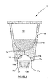
- the separating vessel 10 comprises a container having an interior receiving zone 13 for the molten materials 11, 12, as shown in Figure 1 .
- the vessel 10 of the invention further includes a low level outlet aperture 14 which is of a relatively small diameter, and will permit the collector material 12 to drain through such aperture 14 by gravity, while the molten slag 11 will substantially be prevented from passing through the aperture 14 as a result of the higher viscosity and/or lower density of the molten slag 11.
- a separation surface 15 is provided on the exterior of the container 10 in the zone of the outlet aperture 14, such separation surface 15 being adapted to separate any molten slag 11 a which may trickle through the outlet aperture 14, from the molten collector material 12a, Figure 3 and Figure 4 .
- this separating surface 15 is in the form of a concave surface which is concentrically arranged relative to the axis of the outlet aperture 14. It has been found that with the arrangement of the invention, molten slag droplets 11a tend to cling to the concave surface 15, and are carried laterally away from the outlet aperture 14 ultimately to gather at a rim 15a of the concave surface from which they drop downwardly under the force of gravity, Figure 3 . This behaviour of the molten slag droplets 11 a can be ascribed to the low density of the slag material 11 and/or its surface tension.
- the collector material 12a, Figure 3 on the other hand having different physical characteristics in respect of density and surface tension tends to pour directly vertically downwardly from the exit of the outlet aperture 14 under the force of gravity.
- the molten collector material 12a is collected in a collection vessel 17, while the molten slap drops 11 a are transported laterally beyond the collection vessel 17 for separate collection.
- a further feature of the invention comprises an intermediate outlet 16 for molten slag 11 in the side wall of the container 10 in a position spaced vertically upwardly from the outlet aperture 14 for collector material 12.
- the purpose of this intermediate slag outlet 16 is to drain the majority of molten slag 11 from the separating container while the molten collector material 12 is being drained through the outlet aperture 14.
- the relatively small portion of slag 11 which ultimately remains in the separation vessel 10 after draining of the collector material 12 can thus readily be removed from the container 10 by inversion thereof, or tilting thereof, not shown.
- PGM's Platinum Group Metals
- an ore sample will be comminuted and mixed with a flux material, and introduced into a reaction vessel.
- the flux will be caused to fuse to produce a molten slag and a molten collector material such as lead, silver, etc, which acts to collect the PGM's.
- the molten mixture is then introduced into the separating vessel 10 of the invention in order to separate the molten collector material 12 from the molten slag 11 as described above.
- the separating vessel 10 of the invention could also act as the reaction vessel.
- the separation surface 15 could for example merely comprise a surface which is angled to the vertical in a single plane or in several planes whereby molten slag drops 11 a are carried transversely away from outlet duct 14 for separate collection.
- the separation surface 15 could be could be conical.
Landscapes
- Engineering & Computer Science (AREA)
- Life Sciences & Earth Sciences (AREA)
- Chemical & Material Sciences (AREA)
- Health & Medical Sciences (AREA)
- Physics & Mathematics (AREA)
- General Engineering & Computer Science (AREA)
- Food Science & Technology (AREA)
- Medicinal Chemistry (AREA)
- Mechanical Engineering (AREA)
- Analytical Chemistry (AREA)
- Biochemistry (AREA)
- General Health & Medical Sciences (AREA)
- General Physics & Mathematics (AREA)
- Immunology (AREA)
- Pathology (AREA)
- Sampling And Sample Adjustment (AREA)
- Furnace Details (AREA)
Description
- THIS invention relates to a separating vessel particularly suitable for, but not limited to, use in mineral sample analysis.
- In the field of fire assaying, mineral samples are mixed with a flux in a reaction vessel and fused to form a molten flux and molten collector material which collects a metal to be assayed. In conventional fire assay methods, the flux and collector material are caused to solidify and thereafter separated mechanically.
- It is accordingly an object of the present invention to provide a novel separating vessel suitable for separating molten slag from a molten collector material in a mineral sample analysis method such as a fire assay process.
- According to the invention there is provided a separating
vessel 10 suitable for use in the treatment of a mineral sample wherein amolten slag 11 is separated from amolten collector material 12 comprising a container defining aninterior cavity 13 for receiving themolten materials outlet aperture 14 leading from theinterior cavity 13 to the exterior of the container characterised in that a separatingsurface 15 comprising a downwardly directed concave surface is associated with theoutlet aperture 14 and shaped to cause droplets offlux 11 a to be carried alongsuch surface 15, while droplets ofcollector material 12a drip off such surface 1 by the force of gravity. - Such concave surface is preferably concentrically arranged relative to the outlet aperture.
- Further according to the arrangement, the outlet aperture has dimensions such that the collector material passes through the aperture under the force of gravity, while the molten flux material is substantially prevented from passing through the outlet aperture.
- Thus with the above arrangement, the majority of molten flux will be arrested at the outlet aperture, but a small portion which may pass through the outlet aperture, will be separated from the collector material by the separating surface. This could for example take place where the outlet aperture is gradually enlarged through use.
- In a preferred arranged the outlet aperture will be disposed at low level in the interior cavity, and a slag outlet will be provided in the container spaced vertically upwardly from the outlet aperture, the arrangement being one wherein molten slag which overlies the collector material in the molten state will drain from the slag outlet during the process of draining the collector material through the outlet aperture. Molten slag which ultimately remains in the separating vessel after removal of the collector material can be removed from the vessel for example by tilting or inverting the vessel.
- Also included separately within the scope of the invention is a method of separating molten collector material from molten slag suitable for use in the treatment of a mineral sample comprising the steps of:
- providing the separating vessel of the invention;
- introducing a mixture of molten slag and molten collector material into the vessel whereby the slag settles above the collector material as a result of density differentials;
- draining the collector material through the outlet aperture under the force of gravity while the slag is substantially arrested by the outlet aperture;
- further separating the collector material from the slag which has passed through the outlet aperture at the separating surface where at collector material runs vertically downwardly from the exit of the outlet aperture under the force of gravity while the slag is displaced laterally along the separating surface.
- Further according to the invention the method includes the step of draining slag through the slag outlet. Preferably, slag will drain through the outlet during or prior to draining the collector material through the outlet aperture.
- The invention is further described in the preferred embodiment described hereunder purely by way of example with reference to the accompanying drawings wherein:
- Figure 1
- is a schematic sectioned elevation of a separating vessel in accordance with the invention; and
- Figures 2 to 4
- are schematic sectioned elevations of the separating vessel in
Figure 1 , illustrating various steps in separating a molten slag from a molten collector material in fire forming part of a fire assay process. - Referring to the drawings, the invention provides a novel
separating vessel 10 for separatingmolten slag 11 frommolten collector material 12 for example in a fire assay process. - The separating
vessel 10 comprises a container having aninterior receiving zone 13 for themolten materials Figure 1 . - The
vessel 10 of the invention further includes a lowlevel outlet aperture 14 which is of a relatively small diameter, and will permit thecollector material 12 to drain throughsuch aperture 14 by gravity, while themolten slag 11 will substantially be prevented from passing through theaperture 14 as a result of the higher viscosity and/or lower density of themolten slag 11. - It is a feature of the invention that a
separation surface 15 is provided on the exterior of thecontainer 10 in the zone of theoutlet aperture 14,such separation surface 15 being adapted to separate anymolten slag 11 a which may trickle through theoutlet aperture 14, from themolten collector material 12a,Figure 3 andFigure 4 . - In the arrangement illustrated, this
separating surface 15 is in the form of a concave surface which is concentrically arranged relative to the axis of theoutlet aperture 14. It has been found that with the arrangement of the invention,molten slag droplets 11a tend to cling to theconcave surface 15, and are carried laterally away from theoutlet aperture 14 ultimately to gather at arim 15a of the concave surface from which they drop downwardly under the force of gravity,Figure 3 . This behaviour of themolten slag droplets 11 a can be ascribed to the low density of theslag material 11 and/or its surface tension. Thecollector material 12a,Figure 3 , on the other hand having different physical characteristics in respect of density and surface tension tends to pour directly vertically downwardly from the exit of theoutlet aperture 14 under the force of gravity. - In the arrangement illustrated, the
molten collector material 12a is collected in acollection vessel 17, while the molten slap drops 11 a are transported laterally beyond thecollection vessel 17 for separate collection. - A further feature of the invention comprises an
intermediate outlet 16 formolten slag 11 in the side wall of thecontainer 10 in a position spaced vertically upwardly from theoutlet aperture 14 forcollector material 12. The purpose of thisintermediate slag outlet 16 is to drain the majority ofmolten slag 11 from the separating container while themolten collector material 12 is being drained through theoutlet aperture 14. The relatively small portion ofslag 11 which ultimately remains in theseparation vessel 10 after draining of thecollector material 12 can thus readily be removed from thecontainer 10 by inversion thereof, or tilting thereof, not shown. - Thus in use, for example in a fire assay process for determining the concentration of PGM's (Platinum Group Metals) in an ore sample, such ore sample will be comminuted and mixed with a flux material, and introduced into a reaction vessel. The flux will be caused to fuse to produce a molten slag and a molten collector material such as lead, silver, etc, which acts to collect the PGM's. The molten mixture is then introduced into the
separating vessel 10 of the invention in order to separate themolten collector material 12 from themolten slag 11 as described above.
In certain cases the separatingvessel 10 of the invention could also act as the reaction vessel. - It has been found that with the method described above, sufficient and effective separation of the
molten slag 11 andmolten collector material 12 can be achieved to enable further analysis of thecollector material 12 and entrained PGM's. - Doubtless many variations are possible without departing from the principles set out in the consistory clauses. Thus, the
separation surface 15 could for example merely comprise a surface which is angled to the vertical in a single plane or in several planes whereby molten slag drops 11 a are carried transversely away fromoutlet duct 14 for separate collection. Alternatively, theseparation surface 15 could be could be conical.
Claims (7)
- A separating vessel 10 suitable for use in the treatment of a mineral sample wherein a molten slag 11 is separated from a molten collector material 12 comprising a container defining an interior cavity 13 for receiving the molten materials 11, 12, an outlet aperture 14 leading from the interior cavity 13 to the exterior of the container characterised in that a separating surface 15 comprising a downwardly directed concave surface is associated with the outlet aperture 14 and shaped to cause droplets of flux 11a to be carried along such surface 15, while droplets of collector material 12a drip off such surface 15 by the force of gravity.
- The separating vessel according to claim 1 characterised in that the concave surface 15 is concentrically disposed relative to the outlet aperture 14.
- The separating vessel according to any one of claims 1 or 2 characterised in that the outlet aperture 14 has dimensions such that the collector material 12 passes through the aperture 14 under the force of gravity, while the molten slag 11 material is substantially prevented from passing through the outlet aperture 14, so that the majority of molten slag 11 will be arrested at the outlet aperture 14, but a small portion of slag 11a which may pass through the outlet aperture 14 is separated from the collector material 12 by the separating surface 15.
- The separating vessel according to claims 1 to 3 characterised in that the outlet aperture 14 is disposed at low level in the interior cavity 13, and a slag outlet 16 is provided in the container spaced vertically upwardly from the outlet aperture 14, the arrangement being one wherein molten slag 11 which overlies the collector material 12 in the molten state will drain from the slag outlet 16 during the process of draining the collector material 12 through the outlet aperture 14.
- A method of separating molten collector material 12 from molten slag 11 suitable for use in the treatment of a mineral sample characterised in the steps of providing the separating vessel 10 claimed in any one of claims 1 to 4:introducing a mixture of molten slag 11 and molten collector material 12 into the vessel whereby the slag 11 settles above the collector material 12 as a result of density differentials;draining the collector material 12 through the outlet aperture 14 under the force of gravity while the slag 11 is substantially arrested by the outlet aperture;further separating the collector material 12 from the slag 11 which has passed through the outlet aperture 14 at the separating surface 15 whereat collector material 12 runs generally vertically downwardly from the exit of the outlet aperture 14 under the force of gravity while the slag 11 is displaced laterally along the separating surface 15.
- The method according to claim 5 characterised in that a slag outlet 16 is provided vertically upwardly spaced from the collector material outlet 14 including the step of draining the slag 11 through the slag outlet 16.
- The method according to claim 6 characterised in that slag 11 is drained through the slag outlet 16 during or prior to draining the collector material 12 through the collector material outlet aperture 14.
Applications Claiming Priority (3)
| Application Number | Priority Date | Filing Date | Title |
|---|---|---|---|
| ZA200209262 | 2002-11-14 | ||
| ZA292600002 | 2002-11-14 | ||
| PCT/ZA2003/000132 WO2004044578A1 (en) | 2002-11-14 | 2003-09-12 | Separating vessel |
Publications (2)
| Publication Number | Publication Date |
|---|---|
| EP1561103A1 EP1561103A1 (en) | 2005-08-10 |
| EP1561103B1 true EP1561103B1 (en) | 2008-04-16 |
Family
ID=32313384
Family Applications (1)
| Application Number | Title | Priority Date | Filing Date |
|---|---|---|---|
| EP03755881A Expired - Lifetime EP1561103B1 (en) | 2002-11-14 | 2003-09-12 | Separating vessel |
Country Status (11)
| Country | Link |
|---|---|
| US (1) | US7473394B2 (en) |
| EP (1) | EP1561103B1 (en) |
| AP (1) | AP1885A (en) |
| AT (1) | ATE392613T1 (en) |
| AU (1) | AU2003273384B2 (en) |
| BR (1) | BR0316366B1 (en) |
| CA (1) | CA2511533C (en) |
| DE (1) | DE60320442T2 (en) |
| EA (1) | EA006693B1 (en) |
| WO (1) | WO2004044578A1 (en) |
| ZA (1) | ZA200503908B (en) |
Families Citing this family (2)
| Publication number | Priority date | Publication date | Assignee | Title |
|---|---|---|---|---|
| WO2013183031A1 (en) | 2012-06-08 | 2013-12-12 | Imp Automation (Pty) Ltd | Separating system and method |
| CN115298331A (en) | 2020-02-19 | 2022-11-04 | Fl史密斯公司 | Apparatus and method for separating slag material from collector material |
Family Cites Families (7)
| Publication number | Priority date | Publication date | Assignee | Title |
|---|---|---|---|---|
| US777725A (en) * | 1904-03-12 | 1904-12-20 | Morgan Crucible Co | Cupel. |
| NL6606648A (en) * | 1966-04-07 | 1967-10-09 | ||
| US3516478A (en) * | 1967-12-05 | 1970-06-23 | Monsanto Co | Apparatus for separation of impurities from metal melts in a filament spinning device |
| US4769006A (en) * | 1985-05-13 | 1988-09-06 | Kos Medical Technologies, Ltd. | Hydrodynamically propelled pacing catheter |
| SE454208B (en) * | 1986-02-24 | 1988-04-11 | Asea Ab | SET FOR SEPARATION OF INCLUSIONS IN METAL MELTER AND DEVICE FOR IMPLEMENTATION OF THE SET |
| US6074598A (en) * | 1998-06-15 | 2000-06-13 | Tetron, Inc. | Method and apparatus for slag separation sensing |
| BR0112301B1 (en) * | 2000-07-12 | 2013-03-19 | Method of analysis of a mineral sample for the determination of the concentration of selected metals in a sample. |
-
2003
- 2003-09-12 EP EP03755881A patent/EP1561103B1/en not_active Expired - Lifetime
- 2003-09-12 AT AT03755881T patent/ATE392613T1/en not_active IP Right Cessation
- 2003-09-12 BR BRPI0316366-0A patent/BR0316366B1/en not_active IP Right Cessation
- 2003-09-12 US US10/534,759 patent/US7473394B2/en not_active Expired - Fee Related
- 2003-09-12 WO PCT/ZA2003/000132 patent/WO2004044578A1/en not_active Ceased
- 2003-09-12 EA EA200500806A patent/EA006693B1/en not_active IP Right Cessation
- 2003-09-12 AU AU2003273384A patent/AU2003273384B2/en not_active Ceased
- 2003-09-12 DE DE2003620442 patent/DE60320442T2/en not_active Expired - Lifetime
- 2003-09-12 AP AP2005003322A patent/AP1885A/en active
- 2003-09-12 CA CA2511533A patent/CA2511533C/en not_active Expired - Fee Related
-
2005
- 2005-05-16 ZA ZA200503908A patent/ZA200503908B/en unknown
Also Published As
| Publication number | Publication date |
|---|---|
| WO2004044578A1 (en) | 2004-05-27 |
| DE60320442D1 (en) | 2008-05-29 |
| US20060170139A1 (en) | 2006-08-03 |
| AU2003273384A1 (en) | 2004-06-03 |
| AU2003273384B2 (en) | 2009-03-26 |
| AP2005003322A0 (en) | 2005-06-30 |
| CA2511533C (en) | 2012-07-10 |
| EA200500806A1 (en) | 2005-12-29 |
| BR0316366A (en) | 2005-10-04 |
| ATE392613T1 (en) | 2008-05-15 |
| EA006693B1 (en) | 2006-02-24 |
| DE60320442T2 (en) | 2009-06-04 |
| BR0316366B1 (en) | 2012-10-30 |
| US7473394B2 (en) | 2009-01-06 |
| ZA200503908B (en) | 2008-09-25 |
| CA2511533A1 (en) | 2004-05-27 |
| EP1561103A1 (en) | 2005-08-10 |
| AP1885A (en) | 2008-09-14 |
Similar Documents
| Publication | Publication Date | Title |
|---|---|---|
| KR100229096B1 (en) | Apparatus for assessing cleanliness of metals and methods thereof | |
| CA2112605A1 (en) | Fire refining precious metals assay method | |
| EP1561103B1 (en) | Separating vessel | |
| WO2002004919A3 (en) | Method and apparatus for the assay of precious metals | |
| CA2348522A1 (en) | Method and apparatus for preparing a sample for analysis | |
| HU188773B (en) | Sampler for metal melts | |
| US4783417A (en) | System for on-line molten metal analysis | |
| EP0293502A1 (en) | Method for analysis of molten metal | |
| ATE264405T1 (en) | DEVICE AND METHOD FOR REMOVING SCABES WITH INCREASED ZINC YIELD FROM A VESSEL CONTAINING ZINC MEL | |
| WO2009007911A2 (en) | Melt separation apparatus and method for assaying mineral ore samples using the same | |
| Song et al. | Influence of bottom bubbling rate on formation of metal emulsion in Al–Cu alloy and molten salt system | |
| WO2003100412A2 (en) | Method of ore treatment | |
| JPH1038897A (en) | Nozzle chip discarding device | |
| JP2000221184A (en) | Molten metal sampling device, method and member therefor | |
| AU2003204576B2 (en) | Method of mineral treatment | |
| JPH055496Y2 (en) | ||
| JP2721647B2 (en) | Apparatus and method for sampling molten metal | |
| RU2068013C1 (en) | Method of determining concentration of metals in aluminium drosses | |
| JPH07120455A (en) | Molten metal sampling device | |
| JP2586634Y2 (en) | Molten metal sampling probe | |
| JP3044448B2 (en) | Molten metal sampling equipment | |
| JPH08262008A (en) | Method of manufacturing sample for analysis | |
| AU1964899A (en) | Device for removing slag samples | |
| KR970000630Y1 (en) | Slag inflow crucible | |
| JP2025516086A (en) | Systems and methods for separating materials from crushed lithium ion batteries |
Legal Events
| Date | Code | Title | Description |
|---|---|---|---|
| PUAI | Public reference made under article 153(3) epc to a published international application that has entered the european phase |
Free format text: ORIGINAL CODE: 0009012 |
|
| 17P | Request for examination filed |
Effective date: 20050518 |
|
| AK | Designated contracting states |
Kind code of ref document: A1 Designated state(s): AT BE BG CH CY CZ DE DK EE ES FI FR GB GR HU IE IT LI LU MC NL PT RO SE SI SK TR |
|
| AX | Request for extension of the european patent |
Extension state: AL LT LV MK |
|
| DAX | Request for extension of the european patent (deleted) | ||
| 17Q | First examination report despatched |
Effective date: 20070613 |
|
| GRAP | Despatch of communication of intention to grant a patent |
Free format text: ORIGINAL CODE: EPIDOSNIGR1 |
|
| GRAS | Grant fee paid |
Free format text: ORIGINAL CODE: EPIDOSNIGR3 |
|
| RIN1 | Information on inventor provided before grant (corrected) |
Inventor name: HOHENSTEIN, BOYNE FRIEDRICH |
|
| GRAA | (expected) grant |
Free format text: ORIGINAL CODE: 0009210 |
|
| AK | Designated contracting states |
Kind code of ref document: B1 Designated state(s): AT BE BG CH CY CZ DE DK EE ES FI FR GB GR HU IE IT LI LU MC NL PT RO SE SI SK TR |
|
| REG | Reference to a national code |
Ref country code: CH Ref legal event code: EP |
|
| REG | Reference to a national code |
Ref country code: IE Ref legal event code: FG4D |
|
| REF | Corresponds to: |
Ref document number: 60320442 Country of ref document: DE Date of ref document: 20080529 Kind code of ref document: P |
|
| PG25 | Lapsed in a contracting state [announced via postgrant information from national office to epo] |
Ref country code: SI Free format text: LAPSE BECAUSE OF FAILURE TO SUBMIT A TRANSLATION OF THE DESCRIPTION OR TO PAY THE FEE WITHIN THE PRESCRIBED TIME-LIMIT Effective date: 20080416 |
|
| NLV1 | Nl: lapsed or annulled due to failure to fulfill the requirements of art. 29p and 29m of the patents act | ||
| PG25 | Lapsed in a contracting state [announced via postgrant information from national office to epo] |
Ref country code: NL Free format text: LAPSE BECAUSE OF FAILURE TO SUBMIT A TRANSLATION OF THE DESCRIPTION OR TO PAY THE FEE WITHIN THE PRESCRIBED TIME-LIMIT Effective date: 20080416 Ref country code: FI Free format text: LAPSE BECAUSE OF FAILURE TO SUBMIT A TRANSLATION OF THE DESCRIPTION OR TO PAY THE FEE WITHIN THE PRESCRIBED TIME-LIMIT Effective date: 20080416 Ref country code: PT Free format text: LAPSE BECAUSE OF FAILURE TO SUBMIT A TRANSLATION OF THE DESCRIPTION OR TO PAY THE FEE WITHIN THE PRESCRIBED TIME-LIMIT Effective date: 20080916 Ref country code: ES Free format text: LAPSE BECAUSE OF FAILURE TO SUBMIT A TRANSLATION OF THE DESCRIPTION OR TO PAY THE FEE WITHIN THE PRESCRIBED TIME-LIMIT Effective date: 20080727 |
|
| PG25 | Lapsed in a contracting state [announced via postgrant information from national office to epo] |
Ref country code: AT Free format text: LAPSE BECAUSE OF FAILURE TO SUBMIT A TRANSLATION OF THE DESCRIPTION OR TO PAY THE FEE WITHIN THE PRESCRIBED TIME-LIMIT Effective date: 20080416 |
|
| PG25 | Lapsed in a contracting state [announced via postgrant information from national office to epo] |
Ref country code: DK Free format text: LAPSE BECAUSE OF FAILURE TO SUBMIT A TRANSLATION OF THE DESCRIPTION OR TO PAY THE FEE WITHIN THE PRESCRIBED TIME-LIMIT Effective date: 20080416 Ref country code: SE Free format text: LAPSE BECAUSE OF FAILURE TO SUBMIT A TRANSLATION OF THE DESCRIPTION OR TO PAY THE FEE WITHIN THE PRESCRIBED TIME-LIMIT Effective date: 20080716 |
|
| ET | Fr: translation filed | ||
| PLBE | No opposition filed within time limit |
Free format text: ORIGINAL CODE: 0009261 |
|
| STAA | Information on the status of an ep patent application or granted ep patent |
Free format text: STATUS: NO OPPOSITION FILED WITHIN TIME LIMIT |
|
| PG25 | Lapsed in a contracting state [announced via postgrant information from national office to epo] |
Ref country code: BE Free format text: LAPSE BECAUSE OF FAILURE TO SUBMIT A TRANSLATION OF THE DESCRIPTION OR TO PAY THE FEE WITHIN THE PRESCRIBED TIME-LIMIT Effective date: 20080416 Ref country code: RO Free format text: LAPSE BECAUSE OF FAILURE TO SUBMIT A TRANSLATION OF THE DESCRIPTION OR TO PAY THE FEE WITHIN THE PRESCRIBED TIME-LIMIT Effective date: 20080416 |
|
| 26N | No opposition filed |
Effective date: 20090119 |
|
| PG25 | Lapsed in a contracting state [announced via postgrant information from national office to epo] |
Ref country code: EE Free format text: LAPSE BECAUSE OF FAILURE TO SUBMIT A TRANSLATION OF THE DESCRIPTION OR TO PAY THE FEE WITHIN THE PRESCRIBED TIME-LIMIT Effective date: 20080416 Ref country code: MC Free format text: LAPSE BECAUSE OF NON-PAYMENT OF DUE FEES Effective date: 20080930 |
|
| REG | Reference to a national code |
Ref country code: CH Ref legal event code: PL |
|
| PG25 | Lapsed in a contracting state [announced via postgrant information from national office to epo] |
Ref country code: IE Free format text: LAPSE BECAUSE OF NON-PAYMENT OF DUE FEES Effective date: 20080912 |
|
| PG25 | Lapsed in a contracting state [announced via postgrant information from national office to epo] |
Ref country code: IT Free format text: LAPSE BECAUSE OF FAILURE TO SUBMIT A TRANSLATION OF THE DESCRIPTION OR TO PAY THE FEE WITHIN THE PRESCRIBED TIME-LIMIT Effective date: 20080416 |
|
| PG25 | Lapsed in a contracting state [announced via postgrant information from national office to epo] |
Ref country code: CY Free format text: LAPSE BECAUSE OF FAILURE TO SUBMIT A TRANSLATION OF THE DESCRIPTION OR TO PAY THE FEE WITHIN THE PRESCRIBED TIME-LIMIT Effective date: 20080416 |
|
| PG25 | Lapsed in a contracting state [announced via postgrant information from national office to epo] |
Ref country code: CH Free format text: LAPSE BECAUSE OF NON-PAYMENT OF DUE FEES Effective date: 20080930 Ref country code: LI Free format text: LAPSE BECAUSE OF NON-PAYMENT OF DUE FEES Effective date: 20080930 |
|
| PG25 | Lapsed in a contracting state [announced via postgrant information from national office to epo] |
Ref country code: LU Free format text: LAPSE BECAUSE OF NON-PAYMENT OF DUE FEES Effective date: 20080912 Ref country code: HU Free format text: LAPSE BECAUSE OF FAILURE TO SUBMIT A TRANSLATION OF THE DESCRIPTION OR TO PAY THE FEE WITHIN THE PRESCRIBED TIME-LIMIT Effective date: 20081017 |
|
| PG25 | Lapsed in a contracting state [announced via postgrant information from national office to epo] |
Ref country code: TR Free format text: LAPSE BECAUSE OF FAILURE TO SUBMIT A TRANSLATION OF THE DESCRIPTION OR TO PAY THE FEE WITHIN THE PRESCRIBED TIME-LIMIT Effective date: 20080416 |
|
| PG25 | Lapsed in a contracting state [announced via postgrant information from national office to epo] |
Ref country code: GR Free format text: LAPSE BECAUSE OF FAILURE TO SUBMIT A TRANSLATION OF THE DESCRIPTION OR TO PAY THE FEE WITHIN THE PRESCRIBED TIME-LIMIT Effective date: 20080717 |
|
| REG | Reference to a national code |
Ref country code: DE Ref legal event code: R082 Ref document number: 60320442 Country of ref document: DE Representative=s name: VON ROHR PATENTANWAELTE PARTNERSCHAFT MBB, DE |
|
| REG | Reference to a national code |
Ref country code: FR Ref legal event code: PLFP Year of fee payment: 14 |
|
| PGFP | Annual fee paid to national office [announced via postgrant information from national office to epo] |
Ref country code: GB Payment date: 20160920 Year of fee payment: 14 Ref country code: DE Payment date: 20160921 Year of fee payment: 14 Ref country code: BG Payment date: 20160915 Year of fee payment: 14 |
|
| PGFP | Annual fee paid to national office [announced via postgrant information from national office to epo] |
Ref country code: SK Payment date: 20160912 Year of fee payment: 14 Ref country code: FR Payment date: 20160921 Year of fee payment: 14 Ref country code: CZ Payment date: 20160912 Year of fee payment: 14 |
|
| REG | Reference to a national code |
Ref country code: DE Ref legal event code: R119 Ref document number: 60320442 Country of ref document: DE |
|
| PG25 | Lapsed in a contracting state [announced via postgrant information from national office to epo] |
Ref country code: CZ Free format text: LAPSE BECAUSE OF NON-PAYMENT OF DUE FEES Effective date: 20170912 |
|
| GBPC | Gb: european patent ceased through non-payment of renewal fee |
Effective date: 20170912 |
|
| REG | Reference to a national code |
Ref country code: SK Ref legal event code: MM4A Ref document number: E 3793 Country of ref document: SK Effective date: 20170912 |
|
| REG | Reference to a national code |
Ref country code: FR Ref legal event code: ST Effective date: 20180531 |
|
| PG25 | Lapsed in a contracting state [announced via postgrant information from national office to epo] |
Ref country code: GB Free format text: LAPSE BECAUSE OF NON-PAYMENT OF DUE FEES Effective date: 20170912 Ref country code: SK Free format text: LAPSE BECAUSE OF NON-PAYMENT OF DUE FEES Effective date: 20170912 Ref country code: DE Free format text: LAPSE BECAUSE OF NON-PAYMENT OF DUE FEES Effective date: 20180404 |
|
| PG25 | Lapsed in a contracting state [announced via postgrant information from national office to epo] |
Ref country code: FR Free format text: LAPSE BECAUSE OF NON-PAYMENT OF DUE FEES Effective date: 20171002 |
|
| PG25 | Lapsed in a contracting state [announced via postgrant information from national office to epo] |
Ref country code: BG Free format text: LAPSE BECAUSE OF NON-PAYMENT OF DUE FEES Effective date: 20180405 |