EP1560895B1 - Electrooptic light control element, electrooptic display and control medium - Google Patents
Electrooptic light control element, electrooptic display and control medium Download PDFInfo
- Publication number
- EP1560895B1 EP1560895B1 EP03779850A EP03779850A EP1560895B1 EP 1560895 B1 EP1560895 B1 EP 1560895B1 EP 03779850 A EP03779850 A EP 03779850A EP 03779850 A EP03779850 A EP 03779850A EP 1560895 B1 EP1560895 B1 EP 1560895B1
- Authority
- EP
- European Patent Office
- Prior art keywords
- medium
- temperature
- compounds
- gzu
- modulation
- Prior art date
- Legal status (The legal status is an assumption and is not a legal conclusion. Google has not performed a legal analysis and makes no representation as to the accuracy of the status listed.)
- Expired - Lifetime
Links
- 0 C*(*C(C=C1)=CCC1=*(C)C)c1cc(*)c(*c2cc(*)c(*)c(*)c2)c(*)c1 Chemical compound C*(*C(C=C1)=CCC1=*(C)C)c1cc(*)c(*c2cc(*)c(*)c(*)c2)c(*)c1 0.000 description 2
Images

Classifications
-
- C—CHEMISTRY; METALLURGY
- C09—DYES; PAINTS; POLISHES; NATURAL RESINS; ADHESIVES; COMPOSITIONS NOT OTHERWISE PROVIDED FOR; APPLICATIONS OF MATERIALS NOT OTHERWISE PROVIDED FOR
- C09K—MATERIALS FOR MISCELLANEOUS APPLICATIONS, NOT PROVIDED FOR ELSEWHERE
- C09K19/00—Liquid crystal materials
- C09K19/04—Liquid crystal materials characterised by the chemical structure of the liquid crystal components, e.g. by a specific unit
- C09K19/42—Mixtures of liquid crystal compounds covered by two or more of the preceding groups C09K19/06 - C09K19/40
- C09K19/46—Mixtures of liquid crystal compounds covered by two or more of the preceding groups C09K19/06 - C09K19/40 containing esters
-
- G—PHYSICS
- G02—OPTICS
- G02F—OPTICAL DEVICES OR ARRANGEMENTS FOR THE CONTROL OF LIGHT BY MODIFICATION OF THE OPTICAL PROPERTIES OF THE MEDIA OF THE ELEMENTS INVOLVED THEREIN; NON-LINEAR OPTICS; FREQUENCY-CHANGING OF LIGHT; OPTICAL LOGIC ELEMENTS; OPTICAL ANALOGUE/DIGITAL CONVERTERS
- G02F1/00—Devices or arrangements for the control of the intensity, colour, phase, polarisation or direction of light arriving from an independent light source, e.g. switching, gating or modulating; Non-linear optics
- G02F1/01—Devices or arrangements for the control of the intensity, colour, phase, polarisation or direction of light arriving from an independent light source, e.g. switching, gating or modulating; Non-linear optics for the control of the intensity, phase, polarisation or colour
- G02F1/13—Devices or arrangements for the control of the intensity, colour, phase, polarisation or direction of light arriving from an independent light source, e.g. switching, gating or modulating; Non-linear optics for the control of the intensity, phase, polarisation or colour based on liquid crystals, e.g. single liquid crystal display cells
-
- C—CHEMISTRY; METALLURGY
- C09—DYES; PAINTS; POLISHES; NATURAL RESINS; ADHESIVES; COMPOSITIONS NOT OTHERWISE PROVIDED FOR; APPLICATIONS OF MATERIALS NOT OTHERWISE PROVIDED FOR
- C09K—MATERIALS FOR MISCELLANEOUS APPLICATIONS, NOT PROVIDED FOR ELSEWHERE
- C09K2323/00—Functional layers of liquid crystal optical display excluding electroactive liquid crystal layer characterised by chemical composition
Definitions
- the present invention relates to light control elements, displays containing them, and light control media.
- the light control elements preferably use control media which have anisotropic properties at certain temperatures, such as. B. liquid crystals.
- the light control elements are operated at a temperature at which the control media are in an optically isotropic phase, preferably in the blue phase or in the isotropic phase. In a preferred embodiment, the light control elements are operated at a temperature at which the control media are in the blue phase.
- Light control elements which are operated at a temperature at which the control media are in the isotropic phase are described in DE 102 17 273.0 and DE 102 41 301.0 dated 04.09.2002 (another hitherto unpublished patent applications of the applicant of the present application).
- the present invention relates to an electro-optical light control element and to electro-optical displays and display systems including such elements as television screens and computer monitors, as well as the control media used in the light control elements.
- the light control elements according to the invention contain a mesogenic control medium, which is present in an optically isotropic phase during operation of the light control elements. In addition to a good contrast and a low viewing angle dependency of the contrast, they are particularly distinguished by very short switching times and at the same time low operating voltage.
- the present invention relates to mesogenic media and their use as control media in such light control elements.
- the first mentioned ads are used in combination with a TFT (English: " t hin f ilm t ransistor") control for displays with high information content and high resolution.
- TFT Chinese: " t hin f ilm t ransistor”
- IPS liquid crystal displays
- VAN (English:" v ertically a capitad n ematic )
- VAN displays are a variant of the ECB (English:” electrically c ontrolled b irefringence ”) advertisements
- the MVA advertisements (" m ulti domain v ertically a capitad "), several domains are stabilized per driven electrode and additionally a special optical compensation layer is used.
- DE 10151492 A1 discloses difluoroacrylic acid derivatives, the use of such compounds as components of liquid-crystalline media, a liquid-crystalline medium containing these compounds, a liquid-crystal display element comprising the liquid-crystalline medium and an electro-optical display element containing as a dielectric the liquid-crystalline medium.
- the object of the present invention was therefore to realize particularly fast switching light control elements with good viewing angle dependency and in particular with low drive voltages and a low temperature dependence of the drive voltage and to provide the necessary control media.
- These light control elements should have the smallest possible layer thickness of the control media to as elements of FPDs (English: flat panel displays, so flat Displays), such as flat screens for computers, to be used.
- FPDs English: flat panel displays, so flat Displays
- they should be controllable by means of a very simple electrostatic configuration and have a low operating voltage with a low temperature dependence.
- they should have a good contrast with a low viewing angle dependence for use in electro-optical displays.
- light control elements use the control media in an optically isotropic phase, can be significantly improved, and that in particular light control elements can be realized with significantly reduced characteristic voltages.
- the light control elements according to the invention preferably contain a mesogenic medium which is present in an optically isotropic phase at the operating temperature.
- This medium is conveniently located on or under a substrate.
- the optically isotropic phase may be the isotropic phase or a homogeneous optically isotropic phase, such as a blue phase or an inhomogeneous optically isotropic phase.
- the inhomogeneous optically isotropic phase can consist of a system of mesogenic medium and a polymer.
- the mesogenic medium may be dispersed in the polymer in the form of droplets (PDLC of English "polymer dispersed liquid crystals") or in a contiguous form (PN of English "polymer network”).
- the greetings of the dimensions of the characteristic structures is of the order of magnitude of the wavelength of the light used and preferably smaller than these.
- the control medium at the control temperature or at least one of the control temperatures a blue phase on.
- this blue phase is a homogeneous phase, ie contains no solid (eg polymeric). Material.
- control medium having a homogeneous phase is used.
- control medium of the light control element is at the operating temperature, or at least one of the operating temperatures in the isotropic phase.
- control medium of the light control element is present at the operating temperature, or at least one of the operating temperatures in a blue phase.
- the operating temperature range may extend beyond the blue phase and beyond or upon the occurrence of multiple blue phases over its range and beyond to the isotropic phase.
- Liquid crystals with correspondingly strong chiral twisting can have one or more optically isotropic mesophases. These phases appear at appropriate cholesteric pitch, in a sufficiently large layer thickness slightly bluish. For this reason, they are referred to as blue phases (Gray and Goodby, "Smectic Liquid Crystals, Textures and Structures", Leonhard Hill, USA, Canada (1984)).
- a mesogenic medium is used as the control medium of the light control element.
- Mesogenic media in the present application are media which have a mesophase which are soluble in a mesophase or induce a mesophase.
- the mesophase is a smectic or a nematic phase, preferably a nematic phase.
- the drive medium has a blue phase or several blue phases.
- the blue phase preferably extends or the blue phases extend over a temperature range ( ⁇ T (BP)) with a width of 5 ° or more, preferably of 10 °, particularly preferably of 20 ° or more and very particularly preferably of 30 ° or more.
- the optical anisotropy of the control medium is at a temperature of 4 degrees below the clearing point, preferably 0.080 or more and the control medium preferably has a clearing point in the range of -30 ° C to 80 ° C, preferably up to 55 ° C, on.
- the mesogenic materials As the preferred medium for studying the mesogenic properties of the materials which have no mesophase, the nematic mixture ZLI-4792 from Merck KGaA, Darmstadt, Germany is used.
- the mesogenic materials Preferably, have an extrapolated from 10% solution in this mixture clearing point (T (N, I) or T (N *, I)) of -100 ° C or more, more preferably from -50 ° C or more and more preferably from -20 ° C or more.
- the control medium is located between two substrates. This embodiment is preferred. When the control medium is between two substrates, at least one of these substrates is translucent.
- the translucent substrate, or the translucent Substrates can, for. B. glass, quartz or plastic. If a substrate is used which is not translucent, this may consist, inter alia, of a metal or a semiconductor. These media can be used as such or on a support, such as a ceramic present. If the control medium is a polymeric medium, it may be possible to dispense with the use of a second substrate. Polymer control medium can even be carried out self-supporting. In this case, no substrate is needed at all.
- the operating temperature of the light control element is preferably above the transition temperature of the control medium to the optically isotropic phase, usually in the range of 0.1 ° to 50 ° above this transition temperature, preferably in the range of 0.1 ° to 10 ° above this transition temperature, and more preferably in the range of 0.1 ° to 5 ° above this transition temperature.
- an orientation is induced in the mesogenic medium in the optically isotropic phase which leads to an optical delay, which can be visualized in a known manner.
- an inhomogeneous electric field is used.
- the light control elements according to the invention contain at least one element for the polarization of the light. In addition, they preferably contain a further optical element. This further optical element is either a second element for the polarization of the light, a reflector or a transflector.
- the optical elements are arranged so that the light passes at least once through at least one polarizing element during passage through the mesogenic medium of the light control element both before entering the mesogenic medium, as well as after exiting the mesogenic medium.
- the mesogenic medium is between two polarizers, that is a polarizer and an analyzer.
- two linear polarizers are used.
- the absorption axes of the polarizers are preferably crossed and preferably form an angle of 90 °.
- the light control element according to the invention contains one or more birefringent layers. It preferably contains a ⁇ / 4 layer or a plurality of ⁇ / 4 layers, preferably a ⁇ / 4 layer.
- the optical delay of the ⁇ / 4 layer is preferably about 140 nm.
- the layer thickness (d) of the mesogenic control medium is preferably 0.1 ⁇ m to 5,000 ⁇ m (ie 5 mm), more preferably 0.5 ⁇ m to 1,000 ⁇ m (ie 1 mm), particularly preferably 1.0 ⁇ m to 100 ⁇ m and very particularly preferably 3.0 ⁇ m to 30 ⁇ m and in particular 3.5 ⁇ m to 20 ⁇ m.
- the layer thickness of the mesogenic control medium is preferably 0.5 ⁇ m to 50 ⁇ m, particularly preferably 1.0 ⁇ m to 20 ⁇ m and very particularly preferably 1.0 ⁇ m to 8.0 ⁇ m.
- the present invention also provides electro-optical displays which contain one or more light control elements according to the invention. These electro-optical displays are preferably activated by means of an active matrix.
- the present invention further provides electro-optical display systems comprising one or more electro-optical displays according to the invention.
- These electro-optical display systems are preferably used to display information, inter alia, preferably as a television screen or as a computer monitor.
- the information to be displayed is preferably digital signals or video signals.
- the light control element according to the invention may additionally comprise one or more further conventional optical elements, such as birefringent layers (eg compensation layers), diffuser layers, and elements for increasing the brightness and / or the luminous efficacy and / or the viewing angle dependency, but this enumeration is not exhaustive.
- the light control elements according to the invention are characterized by a good contrast, which depends strongly and almost predominantly on the properties of the polarizers used.
- TN cells having an optical retardation of 0.50 ⁇ m, positive contrast and the absorption axis of the polarizers perpendicular to the preferential orientation of the nematic liquid crystals on the adjacent substrate which do not contain chiral liquid crystals are used here. If the same polarizers are used in the light control elements according to the invention and in these conventional TN cells, the contrast of the light control elements according to the invention is 40% or more greater than that of the TN cells.
- an isocontrast curve of a given contrast ratio in the light control elements according to the invention usually includes an angular range that is more than twice as large, often even more than three times the corresponding angular range of an isocontrast curve for the same contrast ratio in the TN display.
- the switching times of the light control elements according to the invention are very small. They are usually at values of 5 ms or less, preferably 1 ms or less, preferably 0.5 ms or less, more preferably 0.1 ms or less.
- the electro-optical characteristic was characterized by characteristic voltages.
- the voltages were used in which 10%, 50% and 90% relative contrast is achieved. These voltages (V 10 , V 50 and V 90 for short) are also referred to as threshold, mid-gray or saturation voltages.
- the voltage at which 70% relative contrast is reached (V 70 ) was usually determined.
- Electro-optical displays according to the present invention contain one or more light control elements according to the invention. These are controlled in a preferred embodiment by means of an active matrix.
- the light control elements according to the invention are controlled in so-called "field sequential mode".
- the switching elements are illuminated in synchronism with the control successively with different colored light.
- a color wheel, stroboscopic lamps or flash lamps can be used.
- Electro-optical displays according to the present invention may include a color filter for displaying color images.
- This color filter expediently consists of a mosaic of filter elements of different colors.
- each element of the color filter mosaic of a color is typically associated with each electro-optical switching element.
- the light control elements according to the invention contain an electrode structure which generates an electric field with a significant component parallel to the layer of the mesogenic medium.
- This electrode structure may be in the form of interdigital electrodes. It can be in the form of combs or ladders. Also versions in the form of superimposed “H” s and double “T” s and “I” s, respectively, are advantageous.
- the electrode structure is advantageously located on only one side of the mesogenic medium, when using at least one substrate, preferably between this and the mesogenic medium.
- the electrode structure is present in at least two different planes, which are both located on one side of the mesogenic control medium, this is especially true if the electrode structure contains overlapping partial structures.
- These substructures are advantageously separated from each other by a dielectric layer. If the substructures are located on the opposite sides of an insulation layer, a "lay out" can be selected, which allows the realization of capacitors. This is particularly advantageous in the control of displays by means of an active matrix.
- Such active matrix displays use a matrix of control elements assigned to the individual light control elements with a nonlinear current-voltage characteristic, such as, for example, B. TFTs or MIM (English: m etal i nsulator m etal) diodes.
- An essential aspect of the present invention is the design of the electrode structure of the electro-optical switching elements according to the invention.
- various embodiments are possible.
- the preferred embodiments of the electrodes of the light control elements according to the invention are optionally described with reference to the corresponding figures.
- the figure shows schematically in cross section the structure of a switching element or a part of a switching element according to DE 102 172 73.0.
- the control medium (2) Between the inner surfaces of the substrates (1) and (1 ') is the control medium (2).
- the two electrodes (3) and (4) of the electrode structure On the inner surface of the one substrate (1) are the two electrodes (3) and (4) of the electrode structure, which can be acted upon by mutually different potentials.
- “Vop” denotes the voltage, charge or power source.
- the lines emanating from Vop symbolize the electrical supply lines to the electrodes.
- the electrodes may be made of transparent material, such as. For example, indium tin oxide (ITO). In this case, it may be advantageous and possibly necessary to cover a part or parts of the light control element by means of a black mask. This allows areas in which the electric field is not effective to shield and thus improve the contrast.
- the electrodes may also be made of opaque material, usually of metal, e.g. made of chrome, aluminum, copper, silver or gold, preferably chrome. In this case, the use of a separate black mask may be omitted.
- the electric field used is preferably an inhomogeneous field.
- the electrodes preferably have a distance from one another in the range from 0.5 ⁇ m to 100 ⁇ m, preferably in the range from 1 ⁇ m to 20 ⁇ m, particularly preferably in the range from 1 ⁇ m to 15 ⁇ m, very particularly preferably in the range from 2 ⁇ m to 12 ⁇ m and most preferably in the range of 3 ⁇ m to 11 ⁇ m.
- the distance between the electrodes is preferably 19 ⁇ m or less, particularly preferably 15 ⁇ m or less, very particularly preferably 10 ⁇ m or less and particularly preferably 9 ⁇ m or less.
- the width of the electrodes in the direction to the neighboring electrodes, which can be subjected to different potential, is less critical than the distance of the electrodes in this direction. It has almost no influence on the characteristic voltages of the light control elements. As the width of the electrodes increases, however, the aperture ratio of the light control element becomes smaller and the brightness becomes smaller decreases, especially if the electrodes are made of opaque material. With decreasing width of the electrodes, on the other hand, their electrical resistance increases.
- the electrodes preferably have a width in the range of 0.5 ⁇ m to 30 ⁇ m, preferably in the range of 0.5 ⁇ m to 20 ⁇ m, particularly preferably in the range of 0.7 ⁇ m to 19 ⁇ m, very particularly preferably in the range of 1 microns to 9 microns, and most preferably in the range of 1.5 microns to 6 microns.
- the mesogenic media have a nematic phase or a cholesteric one.
- This optically isotropic phase is preferably a blue phase, but may also be the isotropic phase.
- the temperature range of the blue phase is relatively narrow and extends only a few degrees or less.
- the clearing point of the control media which have a transition from the nematic phase or the cholesteric phase into the isotropic phase (T (N, I) or T (N *, I)), as well as the transformation temperature (T (N *, BP) ) of the media having a blue phase, is preferably in the range of -20 ° C, preferably -30 ° C to 80 ° C, preferably to 60 ° C, more preferably in the range of 0 ° C to 60 ° C, preferably to 55 ° C and most preferably in the range of 20 ° C to 60 ° C, preferably to 50 ° C.
- the clearing point or transition temperature is preferably in the range of 10 ° C to 70 ° C, and more preferably in the range of 30 ° C to 50 ° C.
- the nematic phase is preferably stable to low temperatures of up to -10 ° C., more preferably to - 30 ° C and most preferably to -40 ° C.
- the control media in this embodiment have a lowest possible enthalpy of enthalpy, ie an enthalpy ( ⁇ H) during the transition from the mesophase, preferably from the namatic or the cholesteric phase, into the isotropic phase.
- the purifying enthalpy is preferably 1.50 J / g or less, more preferably 1.00 J / g or less, and most preferably 0.80 J / g or less.
- control media has a purifying enthalpy of less than 0.90 J / g, preferably 0.78 J / g or less, more preferably 0.70 J / g or less, and more particularly preferably 0.60 J / g or less, and more preferably 0.55 J / g or less.
- the inventors of the present invention have found that the control media in this embodiment, in which the control media have a typical clearing point (T (N, I) and T (N *, I)), the largest possible dielectric susceptibility ( ⁇ also called ⁇ av .) should have.
- the dielectric susceptibility is 25 or more, preferably 27 or more, preferably 35.5 or more, preferably 36 or more, more preferably 40 or more and most preferably 55 or more, or 60 or more.
- the mesogenic media according to the present invention are at a temperature in the nematic phase of 4 degrees below the clearing point prefers a birefringence ( ⁇ n) of 0.150 or more and more preferably of 0.200 or more.
- ⁇ n birefringence
- the value of birefringence is virtually unlimited for the application of the invention.
- the control media have a typical clearing point (T (N, I) or T (N *, I)), usually 0.500 or less and usually 0.450 or smaller.
- the value of the birefringence of the media according to the invention is measured here in the nematic phase at a temperature of 4 ° below the clearing point.
- the birefringence of a mixture of the medium and the nematic mixture ZLI-4792 from Merck KGaA becomes 20, just as with individual substances and premixes ° C and extrapolated from the change compared to the mixture ZLI-4792 on the value of the pure medium. 10% of the medium and 90% of the mixture ZLI-4792 are used. If the solubility of the medium is insufficient, it is avoided to a concentration of 5% and if the solubility is still insufficient, the host mixture used is the nematic mixture MLC-6828, as further described below, and if necessary also the concentration of 10 % reduced to 5%. The method of extrapolating the values from the host mixture is used for all corresponding properties of the media, unless they can be investigated at the appropriate temperature in the nematic phase.
- control medium has a blue phase, i. with increasing temperature, the medium from the nematic phase, a smectic phase or the crystalline phase turns into a blue phase.
- the medium can show several blue phases with increasing temperature. As the temperature continues to rise, the medium changes to the isotropic phase at a transition temperature (T (BP, I)).
- the transition temperature (T (BP, I)) is preferably in the range of -20 ° C, preferably -30 ° C to 80 ° C, preferably up to 60 ° C, particularly preferably in the range of 0 ° C to 60 ° C, preferably up to 55 ° C and most preferably in the range of 20 ° C to 60 ° C, preferably to 50 ° C.
- Clarification point preferably in the range of 10 ° C to 70 ° C and more preferably in the range of 30 ° C to 50 ° C.
- the dielectric susceptibility ( ⁇ ) of the control medium at a temperature of 4 ° above the transition temperature (T (BP, I)) of the medium is 25 or more, preferably 27 or more, preferably 35.5 or more, preferably 36 or more, more preferably 40 or more, and most preferably 55 or more, or 60 or more.
- the mesogenic media according to the present invention preferably have a dipole moment of 4 or more, more preferably 6 Debye or more and more preferably 8 Debye or more.
- both mesogenic control media can be used, which have a positive dielectric anisotropy ( ⁇ ) in the mesophase, as well as those which have a negative dielectric anisotropy.
- the mesogenic control media When the mesogenic control media has a positive dielectric anisotropy, it has a transition from the nematic phase or cholesteric phase to the isotropic phase at 1 kHz and a temperature of 4 ° below the clearing point, preferably in the nematic phase, for the control media , a value of preferably 15 or more, more preferably 30 or more, and most preferably 45 or more. If the medium does not have a nematic phase, or if it is not in the nematic phase at a temperature of 4 ° below the isotropic phase transition, its dielectric anisotropy, such as birefringence, is determined by extrapolating the values of a corresponding host mixture.
- its dielectric anisotropy such as birefringence
- the mesogenic control media have a negative dielectric anisotropy, this has a transition from the control media to the control media nematic phase or from the cholesteric phase to the isotropic phase have a value of preferably -5 or less, more preferably -7 or less, and very particularly preferably at 1 kHz and a temperature of 4 ° below the Klistpurikts, preferably in the nematic phase -10 or less.
- the nematic mixture ZLI-3086 from Merck KGaA is used as the host mixture, if necessary, as for dielectrically negative compounds.
- control media having a positive dielectric anisotropy.
- control media according to the invention have a characteristic in the light control elements according to the invention at a temperature of 2 degrees above the clearing point (T (N, I) or T (N *, I)) or the transition temperature (T (N *, BP)) Voltage V 70 in the range of 5 V to 150 V, preferably from 15 V to 110 V, more preferably from 20 V to 90 V and most preferably from 30 V to 80 V on.
- the control media according to the invention in the light control elements according to the invention at a temperature of 2 degrees above the clearing point or the transition temperature have a characteristic voltage of 105 V or less, preferably 95 V or less, more preferably 75 V or less, and most preferably of 65V or less.
- the control media according to the invention preferably have a low temperature dependence of the characteristic voltage V 70 at a temperature of 2 degrees above the clearing point (T (N, I) or T (N *, I)) or the transition temperature (T ( N *, BP)), ie dV / dT (T (N, I) + 2 °) or dV / dT (T (N *, I) + 2 °) or dV / dT (T (N *, BP) + 2 °) over a temperature range of one degree below to one degree above given Temperature in the range of 1 V / ° to 20 V / °, preferably from 1 V / ° to 15 V / °, more preferably from 2 V / ° to 10 V / ° and most preferably from 2 V / ° to 7 V. / ° on. This is especially true for the media which have a transition from the nematic or cholesteric phase to the
- control media according to the invention in the light control elements according to the invention even a small temperature dependence of the characteristic voltage V 70 at a temperature of 2 degrees above the clearing point (T (N, I) or T (N *, I)) or the transition temperature (T (N *, BP)), ie dV / dT (T (N, I) + 2 °) or dV / dT (T (N *, I) + 2 °) or dV / dT ( T (N *, BP) + 2 °) over a temperature range of one degree below to one degree above the given temperature.
- the mesogenic media according to the present invention preferably consist of two to 40 compounds, more preferably from five to 30 compounds, and most preferably from seven to 25 compounds.
- the media contain one or more compounds of the formula I and preferably consist predominantly and particularly preferably almost completely of one or more compounds of the formula I.
- novel media particularly preferably contain one or more compounds of the formula I, preferably of the formula I-1 and / or of the formula I-2, in which X 1 is CF 3 .
- the media according to the invention preferably comprise one or more compounds selected from the group of the compounds of the formulas II1 to II-5, preferably compounds in which Z 22 is -CO-O-.
- component A of the media according to the invention preferably contains one or more compounds of the formula II and particularly preferably consists predominantly and very particularly preferably almost completely of one or more compounds of the formula II.
- both mesogenic control media can be used, which in the mesophase, preferably in the nematic phase, a positive have dielectric anisotropy ( ⁇ ), as well as those which have a negative dielectric anisotropy. Preference is given to using mesogenic control media which have a positive dielectric anisotropy ( ⁇ ) in the mesophase.
- the mesogenic control media When the mesogenic control media has a positive dielectric anisotropy, it has a control frequency at 1 kHz and a temperature of 4 ° below the clearing point and below T, respectively, at the control media having a nematic or cholesteric phase to isotropic phase transition (N *, BP), preferably in the nematic phase, preferably 40 or more.
- N *, BP nematic or cholesteric phase to isotropic phase transition
- the mesogenic media according to the present invention having positive dielectric anisotropy particularly preferably consists predominantly, and most preferably almost completely, of component A.
- the mesogenic media according to the present invention having positive dielectric anisotropy contain one or more components selected from the group of components B to D, preferably selected from the group of components B and D, particularly preferably component B.
- the mesogenic media according to the present invention having negative dielectric anisotropy particularly preferably consists predominantly, and most preferably almost completely, of component D.
- Component D of these media preferably contains one or more compounds.
- the mesogenic medium according to the present invention may contain further additives and chiral dopants in usual concentrations.
- the total concentration of these other ingredients is in the range of 0% to 10%, preferably in the range of 0, 1% to 6%, based on the total mixture.
- the concentrations of each of these compounds are in the range of 0.1 to 3%.
- the concentration of these compounds and similar components of the mixture, with the exception of the chiral dopants in the media which have a blue phase, are not taken into account in the indication of the concentration ranges of the remaining mixture components.
- the media are obtained from the compounds in the usual way. Conveniently, the compounds which are used in lesser amounts are dissolved in the compounds used in larger quantities. If the temperature during the mixing process above the Klär point of the predominant component increases, the completeness of the resolution can be easily observed.
- the media according to the invention can also be prepared in other ways. So by the use of premixes. As premixes, inter alia, homolog mixtures and / or eutectic mixtures can be used become. The premixes can also be self-usable media. This is the case with so-called two-bottle or multi-bottle systems ("two-bottle” or “multi-bottle systems").
- the specified ranges of values preferably include the limits.
- the concentrations are given in mass% and refer to the complete mixture. Temperatures are given in degrees Celsius and temperature differences in degrees Celsius. All physical properties were determined as in "Merck Liquid Crystals, Physical Properties of Liquid Crystals", as of Nov. 1997, Merck KGaA, Germany and are given for a temperature of 20 ° C, unless explicitly stated otherwise.
- the optical anisotropy ( ⁇ n), also called birefringence, is determined at a wavelength of 589.3 nm.
- the dielectric properties are determined at a frequency of 1 kHz.
- Dielectric positive compounds have a ⁇ > 1.5
- dielectrically neutral compounds have a ⁇ in the range -1.5 ⁇ ⁇ ⁇ 1.5
- dielectrically negative compounds have a ⁇ ⁇ -1.5.
- the same definitions apply to components of mixtures and mixtures.
- Dielectric properties, electro-optic properties (eg threshold voltages) and switching times were determined in test cells made by Merck KGaA, Darmstadt, Germany.
- the test cells for determining ⁇ had a layer thickness of 22 ⁇ m and a circular electrode made of indium tin oxide (ITO) with an area of 1.13 cm 2 and a guard ring.
- ITO indium tin oxide
- For homeotropic orientation to determine ⁇ cells with a homeotropically orienting polyimide alignment layer were used.
- lecithin Merck KGaA
- the cells for the determination of ⁇ ⁇ had orientation layers of the polyimide AL-1054 from Japan Synthetic Rubber, Japan.
- Capacities were typically measured with a Solatron 1260 frequency analyzer with a square wave with an effective voltage of 0.3 V rms .
- the electrophotographic examinations were performed with white light. The characteristic stresses were determined under vertical observation.
- the dielectric properties of the materials are at 1.kHz and 20 ° C, as well as control media having a transition from the nematic or cholesteric phase to the isotropic phase (T (N, I)) at a temperature of 4 ° below and at a temperature of 4 ° above the clearing point (T (N, I) or T (N *, I)) again at 1 kHz, respectively, and control media having a transition from the blue phase to the isotropic phase at a temperature of 4 ° above the corresponding transition temperature (T (N *, BP)) of the respective material, but here at 30 Hz.
- the dielectric anisotropy ( ⁇ ) of the compounds is determined by extrapolation of the values of a 10% solution of the respective compound in a host mixture at 20 ° C. to a proportion of the respective compound of 100%.
- the capacities of the test mixtures are determined both in a cell with homeotropic and in a cell with homogeneous boundary orientation.
- the layer thickness of both cell types is approximately 20 ⁇ m.
- a square wave with a frequency of 1 kHz and an effective voltage (rms, English: root mean square) of typically 0.2 V to 1.0 V is used. In any case, the voltage used is lower than the capacitive threshold of each tested mixture.
- the mixture ZLI-4792 and for dielectrically neutral as well as for dielectrically negative compounds the mixture ZLI-3086, both from Merck KGaA, Germany, is used as the host mixture.
- These host mixtures are also used for components and media that have no nematic phase even at the temperature in question, or that can not be subcooled up to the relevant temperature in the nematic phase. If the solubility of the compounds, components or media in the respective host mixture is less than 10%, the concentration of the substance investigated is exceptionally lowered to 5%.
- the solubility of a dielectrically positive substance (a compound, a component of a medium or a medium) in the host mixture ZLI-4792 is less than 5%
- the nematic mixture MLC-6828, Merck KGaA, Germany is used as the host mixture.
- the concentration of the substance to be examined is halved from 10% to 5%. The change in the values from those of the host mixture is extrapolated to the value of the pure substance.
- the media according to the invention preferably contain 0% to 10% of compounds whose solubility in the corresponding host mixture (ZLI-3086 or MLC-6828) is less than 5%.
- concentration of these compounds is 8% or less, more preferably 5% or less and most preferably 4% or less.
- the dielectric anisotropy of the compounds, components and optionally the media which are at 20 ° C or at a temperature of 4 ° below their clearing point (T (N, I) or (T (N *, I) or their transition temperature (T (N *, BP)) are not present in the nematic phase, or that can not be supercooled up to this temperature in this phase, are determined from a host mixture, as described above for the compounds.
- the dielectric constants ⁇ and ⁇ ⁇ are determined with an absolute accuracy of approx. +/- 0.1 to +/- 0.2, which results in an absolute accuracy of approx. +/- 0 for the dielectric anisotropy ( ⁇ ). 2 to +/- 0.4, typically of +/- 0.3.
- the accuracy decreases with larger values, so the possible deviations increase.
- the absolute accuracy is about +/- 0.5, and for values of more than 40, the absolute accuracy is about +/- 1.0.
- the dielectric susceptibility of the media is determined at a temperature of 4 ° above the temperature of their transition to the optically isotropic phase in the optically isotropic phase. It is called average dielectric susceptibility ( ⁇ av. ).
- ⁇ av. average dielectric susceptibility
- the dielectric susceptibility of the media is typically determined with an absolute accuracy of about +/- 0.1 to +/- 0.2. For large values of dielectric susceptibility, of 30 or more, the absolute accuracy is about +/- 0.5, and for very large values, of 40 or more, or even 60 or more, the absolute accuracy is about +/- 1.
- the enthalpy of clarification was determined by differential scanning calorimetry, DSC for short certainly.
- DSC2920 Texas Instruments, USA was used. 2 mg to 8 mg, typically 4 mg, of the material in question were measured in a pan against an empty pan as a reference. The temperature was increased at a heating rate of 10 degrees / minute. The starting point was chosen about 30 ° to 40 ° below the clearing point of the substance. The end point was in each case about 30 ° above the clearing point of the substance. The relative accuracy of the values is approx. +/- 10% to +/- 15%. For very small values of the enthalpy of clarification, it may be necessary to increase the sample volume or change it to a more precise measuring instrument.
- the value of the birefringence of the erfiridungshielen media is measured here in the Riematischen phase at 20 ° C and at a temperature of 4 ° below the clearing point or the transition temperature T (N *, BP). If the medium at one of these two temperatures or at these two temperatures is not stable nematic or at least supercoolable up to this temperature in the nematic phase, the birefringence of a mixture of the corresponding nematic host mixture is extrapolated, as described above in the determination of the dielectric anisotropy ,
- the cholesteric pitch of the media according to the invention is too short to allow a determination of the anisotropic properties, for example birefringence or dielectric susceptibility
- three options are available for this purpose.
- the first, most preferred option is the replacement of the or each of the chiral compounds used in the media by their racemate.
- the second possibility which is also preferred, is to reduce the concentration of the chiral compound or chiral compounds to a value which makes the cholesteric pitch so large that the determination of the properties becomes possible.
- the third, least preferred option is to compensate for the cholesteric pitch by adding a chiral compound with reverse helix rotation.
- threshold voltage in the present application means the optical threshold and is given for a relative contrast of 10% (V 10 ).
- the midgrain voltage and the saturation voltage are also optically determined and given for a relative contrast of 50% and 90%, respectively.
- V 70 the voltage specified at which the characteristic reaches the value of 70% relative contrast for the first time.
- V 0 the capacitive threshold voltage
- Freedericksz threshold the capacitive threshold voltage
- the media were filled in test cells with interdigital electrodes.
- the layer thickness of the test cells was generally about 10 microns.
- the width of the electrodes was 10 ⁇ m and the distance between the adjacent electrodes was 15 ⁇ m.
- the electro-optical characteristic curve was at a temperature of 2 ° above the clearing point (T (N, I) or T (N *, I)) or the transition temperature from the cholesteric phase to the blue phase (T (N *, BP) ) of the respective medium.
- the increase in the clearing point or the transition temperature T (N *, BP) was in some cases 0.5 ° and up to about 0.7 °. In some (rare) cases, deviations of up to 2 ° or even 4 ° may occur.
- the examination of the electro-optic properties will not be at a temperature of 2 ° above the clearing point of the medium as such (T (N, I) or T (N *, I) or the transition temperature T (N *, BP) as such, but 2 ° above the clearing point of the medium in the cell (T c (N, I) or (T c ( N *, I)) or, respectively, the transition temperature of the medium in the cell (T c (N *, BP)).
- the phase width of the blue phase or the total width of several blue phase becomes, for the media, one or more blue phases , determined from the temperature dependence of the electro-optical effect.
- the temperature at which the electro-optical effect occurs is the temperature at which the optically isotropic phase, the blue phase occurs (T (N *, BP)).
- T (N *, BP) The temperature at which the blue phase, or in the case of media which have more than one blue phase, which disappears as the temperature increases with the last remaining blue phase, and the medium changes into the isotropic phase (T (BP, I)), becomes known from US Pat
- T (BP, I) is determined by interpolation of the temperature dependence of the characteristic voltages above and below this temperature, which in many cases is nearly linear both above and below this temperature.
- This liquid-crystal mixture was filled into a test cell and examined for its electro-optical properties at a temperature of 23.1 ° C, as well as at 24.9 ° C (2 ° above the clearing point).
- the test cell used had interdigital electrodes on only one of the two substrates.
- An electro-optical test cell with a light switching element containing the liquid-crystal mixture was prepared.
- the substrates were made of glass.
- Substrates without orientation layer and without passivation layer were used.
- the electrode structure consisted of intermeshed comb-shaped electrodes. The distance of the electrodes was 15 ⁇ m and the width of the electrodes from each other was 10 ⁇ m.
- the layer thickness of the electrodes was about 100 nm. The electrodes were all in a common plane.
- the layer thickness of the control medium was about 10 microns.
- a first polarizer was used and a second polarizer behind the cell was used as the analyzer.
- the absorption axes of the two polarizers formed an angle of 90 ° to each other.
- the angle between the axis of maximum absorption of the polarizers and the component of the electric field in the plane of the display was each 45 °.
- the voltage-transmission characteristic curve was determined using an electro-optical measuring system DMS 703 from the company Autronic-Melchers, Düsseldorf, Germany. When observed perpendicularly, a curve was obtained which is typical for a cell with electrically controlled birefringence (eg ECB).
- the characteristic voltages of the liquid-crystal switching elements of Examples 1, 2, 5 and 8 are significantly lower than those of Comparative Examples 1 and 2.
- the reduction is already approximately 10% in the comparison of Example 1 to Comparative Example 1 and compared to Comparative Example 2 at about 25%.
- V 70 is 134 V.
- composition Physical Properties connection Conc.
- the mixture is filled into a test cell and analyzed as described in Comparative Example 1. In particular, their electro-optical properties are determined at a temperature of 34.4 ° C.
- the cell thus obtained reached 70% relative contrast at a voltage of 103V.
- composition Physical Properties connection Conc.
- the mixture is filled into a test cell and analyzed as described in Comparative Example 1. In particular, their electro-optical properties are determined at a temperature of 37.6C.
- liquid crystal mixtures having the following composition are prepared and tested.
- Example 1 the mixture was examined for its electro-optical properties at a temperature of 2 above the clearing point in a test cell, in particular V 70 was determined to be 71V.
- the mixture was tested for its electro-optical properties at a temperature of 24.0 ° C in a test cell.
- the value of the threshold voltage (V 10 ) was 40.5 V
- the value of the mid-gray voltage (V 50 ) was 56 V
- the value of the saturation voltage (V 90 ) was 65 V.
- the maximum contrast was reached at 73 V.
- the relative contrast dropped again to 90% and 50%, respectively.
- the control medium of this example has a transition from the nematic (here highly-twisted cholesteric) phase to the blue Phase up. It has a low characteristic voltage V 90 and is characterized by a particularly favorable, low temperature dependence of the characteristic voltages, also in comparison with Examples 1 to 8 of the present application.
- the control medium of this example like that of Example 9, has a transition from the highly-twisted cholesteric phase to the blue phase. It is characterized by a very favorable, low temperature dependence of the characteristic voltages.
- FIG. 1 The figure shows schematically in cross section the structure of a switching element or a part of a switching element according to the present application.
- the control medium (2) Between the inner surfaces of the substrates (1) and (1 ') is the control medium (2).
- the two electrodes (3) and (4) of the electrode structure On the inner surface of the one substrate (1) are the two electrodes (3) and (4) of the electrode structure, which can be acted upon by mutually different potentials.
- Vop refers to the voltage, charge or current source.
- the lines emanating from Vop symbolize the electrical supply lines to the electrodes.
Landscapes
- Chemical & Material Sciences (AREA)
- Crystallography & Structural Chemistry (AREA)
- Physics & Mathematics (AREA)
- Engineering & Computer Science (AREA)
- Nonlinear Science (AREA)
- Materials Engineering (AREA)
- Organic Chemistry (AREA)
- General Physics & Mathematics (AREA)
- Optics & Photonics (AREA)
- Liquid Crystal Substances (AREA)
- Liquid Crystal (AREA)
- Electrochromic Elements, Electrophoresis, Or Variable Reflection Or Absorption Elements (AREA)
- Devices For Indicating Variable Information By Combining Individual Elements (AREA)
Abstract
Description
Die vorliegende Erfindung betrifft Lichtsteuerelemente, diese enthaltende Anzeigen, sowie Lichtsteuermedien. Die Lichtsteuerelemente verwenden bevorzugt Steuermedien die bei bestimmten Temperaturen anisotrope Eigenschaften aufweisen, wie z. B. Flüssigkristalle. Die Lichtsteuerelemente werden bei einer Temperatur betrieben, bei der die Steuermedien in einer optisch isotropen Phase, bevorzugt in der Blauen Phase oder in der isotropen Phase vorliegen. In einer bevorzugten Ausführungsform werden die Lichtsteuerelemente bei einer Temperatur betrieben, bei der die Steuermedien in der Blauen Phase vorliegen. Lichtsteuerelemente die bei einer Temperatur betrieben werden, bei denen die Steuermedien in der isotropen Phase vorliegen, sind in DE 102 17 273.0 und DE 102 41 301.0 vom 04.09.2002 (einer weiteren bislang unveröffentlichten Patentanmeldungen der Anmelderin der vorliegenden Anmeldung) beschrieben.The present invention relates to light control elements, displays containing them, and light control media. The light control elements preferably use control media which have anisotropic properties at certain temperatures, such as. B. liquid crystals. The light control elements are operated at a temperature at which the control media are in an optically isotropic phase, preferably in the blue phase or in the isotropic phase. In a preferred embodiment, the light control elements are operated at a temperature at which the control media are in the blue phase. Light control elements which are operated at a temperature at which the control media are in the isotropic phase are described in DE 102 17 273.0 and DE 102 41 301.0 dated 04.09.2002 (another hitherto unpublished patent applications of the applicant of the present application).
Die vorliegende Erfindung betrifft ein elektrooptisches Lichtsteuerelement sowie solche Elemente enthaltende elektrooptische Anzeigen und Anzeigesysteme wie beispielsweise Fernsehbildschirme und Computermonitore, sowie die in den Lichtsteuerelementen verwendeten Steuermedien. Die erfindungsgemäßen Lichtsteuerelemente enthalten ein mesogenes Steuermedium, das beim Betrieb der Lichtsteuerelemente in einer optisch isotropen Phase vorliegt. Sie sind neben einem guten Kontrast und einer geringen Blickwinkelabhängigkeit des Kontrasts besonders durch sehr kurze Schaltzeiten bei gleichzeitig niedriger Betriebsspannung ausgezeichnet.The present invention relates to an electro-optical light control element and to electro-optical displays and display systems including such elements as television screens and computer monitors, as well as the control media used in the light control elements. The light control elements according to the invention contain a mesogenic control medium, which is present in an optically isotropic phase during operation of the light control elements. In addition to a good contrast and a low viewing angle dependency of the contrast, they are particularly distinguished by very short switching times and at the same time low operating voltage.
Insbesondere betrifft die vorliegende Erfindung mesogene Medien und deren Verwendung als Steuermedien in derartigen Lichtsteuerelementen.In particular, the present invention relates to mesogenic media and their use as control media in such light control elements.
Konventionelle elektrooptischen Flüssigkristallanzeigen sind allgemein bekannt. Sie werden bei einer Temperatur betrieben, bei der sich das Steuermedium in einer in der Regel anisotropen Mesophase befindet. Bei den meisten Anzeigetypen werden die Steuermedien in der nematischen Phase verwendet. In der anisotropen Mesophase haben die Steuermedien bereits anisotrope Eigenschaften, wie zum Beispiel eine Doppelbrechung (Δn). Diese wird nicht erst durch ein elektrisches Feld induziert. Am weitesten verbreitet sind TN- (Englisch: "twisted nematic") und STN-(Englisch: "super twisted nematic") Anzeigen. Die Flüssigkristallzellen dieser Anzeigen haben Elektroden auf den Substraten auf den beiden einander gegenüberliegenden Seiten des Flüssigkristallmediums. Somit ist das elektrische Feld im wesentlichen vertikal zur Flüssigkristallschicht. Insbesondere die zuerst genannten Anzeigen werden in Kombination mit einer TFT (Englisch: "thin film transistor") Ansteuerung für Anzeigen mit großem Informationsgehalt und großer Auflösung verwendet. So zum Beispiel in "lap-top" und "note-book" Computern. Insbesondere bei "desktop" Computermonitoren werden in neuerer Zeit zunehmend Flüssigkristallanzeigen des IPS- (Englisch: in-plane switching", z. B. DE 40 00 451 und EP 0 588 568) oder alternativ des VAN- (Englisch: "vertically aligned nematic") Typs verwendet. VAN-Anzeigen sind eine Variante der ECB- (Englisch:" electrically controlled birefringence") Anzeigen. In einer modernen Variante, den MVA-Anzeigen (Englisch: "multi domain vertically aligned"), werden pro angesteuerter Elektrode mehrere Domänen stabilisiert und zusätzlich wird eine spezielle optische Kompensationsschicht verwendet. Diese Anzeigen verwenden, wie die bereits erwähnten TN-Anzeigen, ein zur Flüssigkristallschicht vertikales elektrisches Feld. Im Gegensatz hierzu verwenden IPS-Anzeigen in der Regel Elektroden auf nur einem Substrat, also an einer Seite der Flüssigkristallschicht; sind also durch eine wesentliche Komponente des elektrischen Felds parallel zur Flüssigkristallschicht gekennzeichnet.Conventional electro-optical liquid crystal displays are well known. They are operated at a temperature at which the control medium is in a generally anisotropic mesophase. For most types of displays, the control media is used in the nematic phase. In the anisotropic mesophase, the control media already have anisotropic properties, such as birefringence (Δn). This is not induced by an electric field. The most widespread are TN (English: " t wisted n ematic") and STN (English: " s uper t wisted n ematic") displays. The liquid crystal cells of these displays have electrodes on the substrates on the two opposite sides of the liquid crystal medium. Thus, the electric field is substantially vertical to the liquid crystal layer. In particular, the first mentioned ads are used in combination with a TFT (English: " t hin f ilm t ransistor") control for displays with high information content and high resolution. For example, in "lap-top" and "note-book" computers. In particular, in "desktop" computer monitors are recently increasingly liquid crystal displays of IPS (English: i n- p lane s witching ", for example, DE 40 00 451 and EP 0588568)., Or alternatively, the VAN (English:" v ertically a ligned n ematic ") VAN displays are a variant of the ECB (English:" electrically c ontrolled b irefringence ") advertisements In a modern variant, the MVA advertisements (" m ulti domain v ertically a ligned "), several domains are stabilized per driven electrode and additionally a special optical compensation layer is used.These displays use, like the already mentioned TN-displays, an electric field vertical to the liquid crystal layer, in contrast IPS displays in the Usually electrodes on only one substrate, so on one side of the liquid crystal layer, so are characterized by an essential component of the electric field parallel to the liquid crystal layer ,
Allen diesen konventionellen Anzeigen ist ein relativ langsames Schatten gemein, insbesondere ist dieses für die immer stärkere Verbreitung findenden TV- und Multi-Media-Anwendungen nicht ausreichend. Dieses fällt insbesondere im Vergleich mit den nahezu ubiquitären Kathodenstrahlröhren auf. Ein weiterer Nachteil der bekannten, in Flüssigkristall= anzeigen eingesetzten elektro-optischen Effekte ist die deutliche Blickwinkelabhängigkeit des erzielten Kontrasts. Diese ist in den meisten Fällen so groß, dass für Anzeigen im Direktsichtbetrieb Kompensationsschichten, typischerweise anisotrope Filme, mit zum Teil kompliziertem Aufbau, verwendet werden müssen.All these conventional displays have a relatively slow shadow in common, in particular, this is not sufficient for the increasingly widespread TV and multi-media applications. This especially in comparison with the almost ubiquitous cathode ray tubes. Another disadvantage of the known electro-optical effects used in liquid crystal displays is the clear viewing angle dependence of the contrast achieved. In most cases, this is so great that compensation layers, typically anisotropic films, sometimes of complicated construction, must be used for direct-view displays.
In DE 102 17 273.0 werden Lichtsteuerelemente beschrieben, bei denen das mesogene Steuermedium bei der Betriebstemperatur in der isotropen Phase vorliegt. Diese Lichtsteuerelemente schalten besonders schnell und haben eine gute Blickwinkelabhängigkeit des Kontrasts. Allerdings sind die Ansteuerspannungen für viele Anwendungen zu hoch. Außerdem ist die, Temperaturabhängigkeit der Ansteuerspannungen sehr groß. Somit besteht der Bedarf nach verbesserten Lichtsteueretementen insbesondere mit verringerter Ansteuerspannung.DE 102 17 273.0 describes light control elements in which the mesogenic control medium is in the isotropic phase at the operating temperature. These light control elements switch very fast and have a good viewing angle dependence of the contrast. However, the drive voltages are too high for many applications. In addition, the temperature dependence of the drive voltages is very high. Thus, there is a need for improved light control devices, in particular with reduced drive voltage.
In der unveröffentlichten Anmeldung DE 102 41 301.0 werden spezielle Elektrodenstrukturen vorgeschlagen, die zu einer signifikanten Verringerung der Betriebsspannungen führen. Allerdings bedingen diese Elektrodenstrukturen einen deutlich größeren Aufwand bei der Herstellung der Lichtsteuerelemente.In unpublished application DE 102 41 301.0, special electrode structures are proposed which lead to a significant reduction of the operating voltages. However, these electrode structures require significantly more effort in the production of the light control elements.
Eine Verringerung der zur Ansteuerung der elektrooptischen Schaltelemente benötigten Spannungen durch entsprechend optimierte Steuermedien erfordert jedoch, im Gegensatz zu den in DE 102 41 301.0 vorgeschlagenen Elektrodenstrukturen, keinen größeren Aufwand bei der Herstellung der Lichtsteuereiemente.However, a reduction in the voltages required to drive the electro-optical switching elements by means of appropriately optimized control media, in contrast to the electrode structures proposed in DE 102 41 301.0, does not require much effort in the production of the light control elements.
DE 10151492 A1 offenbart Difluoracrylsäurederivate, die Verwendung von solchen Verbindungen als Komponenten flüssigkristalliner Medien, ein flüssigkristalliner Medium enthaltend diese Verbindungen, ein Flüssigkristall Anzeigeelement enthlaltend das flüssigkristalline Medium und ein elekrooptisches Anzeigeelement enthaltend als Dielektrikum das flüssigkristalline Medium.DE 10151492 A1 discloses difluoroacrylic acid derivatives, the use of such compounds as components of liquid-crystalline media, a liquid-crystalline medium containing these compounds, a liquid-crystal display element comprising the liquid-crystalline medium and an electro-optical display element containing as a dielectric the liquid-crystalline medium.
Der vorliegenden Erfindung lag somit die Aufgabe zugrunde, besonders schnell schaltende Lichtsteuerelemente mit guter Blickwinkelabhängigkeit und insbesondere mit niedrigen Ansteuerspannungen und einer geringen Temperaturabhängigkeit der Ansteuerspannung zu realisieren und die dafür nötigen Steuermedien bereitzustellen. Diese Lichtsteuerelemente sollen eine möglichst geringe Schichtdicke der Steuermedien aufweisen um als Elemente von FPDs (Englisch: flat panel displays, also flachen Anzeigen), wie zum Beispiel Flachbildschirmen für Computer, eingesetzt werden zu können. Ferner sollen sie mittels einer möglichst einfachen Elektroitenkonfiguration ansteuerbar sein und eine niedrige Betriebsspannung mit einer geringen Temperaturabhängigkeit aufweisen. Darüber hinaus sollen sie für die Anwendung in elektrooptischen Anzeigen einen guten Kontrast mit einer geringen Blickwinkelabhängigkeit haben.The object of the present invention was therefore to realize particularly fast switching light control elements with good viewing angle dependency and in particular with low drive voltages and a low temperature dependence of the drive voltage and to provide the necessary control media. These light control elements should have the smallest possible layer thickness of the control media to as elements of FPDs (English: flat panel displays, so flat Displays), such as flat screens for computers, to be used. Furthermore, they should be controllable by means of a very simple electrostatic configuration and have a low operating voltage with a low temperature dependence. In addition, they should have a good contrast with a low viewing angle dependence for use in electro-optical displays.
Überraschender Weise wurde gefunden, dass, wie im Folgenden beschrieben, Lichtsteuerelemente die Steuermedien in einer optisch isotropen Phase verwenden, deutlich verbessert werden können und, dass insbesondere Lichtsteuerelemente mit deutlich verringerten charakteristischen Spannungen realisiert werden können.Surprisingly, it has been found that, as described below, light control elements use the control media in an optically isotropic phase, can be significantly improved, and that in particular light control elements can be realized with significantly reduced characteristic voltages.
Die elektrooptischen Lichtsteuerelemente gemäß der vorliegenden Erfindung umfassen
- ein Substrat oder mehrere Substrate,
- eine Elektrodenanordnung,
- mindestens ein Element oder mehrere Elemente zur Polarisation des Lichts und
- ein Steuermedium,
- das Lichtsteuerelement bei einer Temperatur betrieben wird, bei der das Steuermedium im nicht angesteuerten Zustand in einer optisch isotropen Phase vorliegt und dass
- die Elektrodenanordnung ein elektrisches Feld mit einer signifikanten Komponente parallel zur Fläche des mesogenen Steuermediums erzeugen kann und, dass
- das mesogene Steuermedium mindestens eine der folgenden Bedingungen (a) und (f) und im Fall, dass es nur die Bedingung (a) erfüllt, mindestens eine der folgenden Bedingungen (b) und (c) und im -Fall, dass es von den Bedingungen (b) und (c) nur die Bedingung (c) erfüllt, mindestens eine der beiden weiteren folgenden Bedingungen (d) und (e) erfüllt, sowie im Fall, dass es die Bedingung (f) erfüllt, optional auch die Bedingung (g) erfüllt
- (a) das Steuermedium weist bei steigender Temperatur einen Übergang von der nematischen Phase oder von der cholesterischen Phase (Ch, hier chirale nematische Phase N* genannt) in die isotrope Phase (T(N,I) bzw. T(N*,I)), also einen typischen Klärpunkt, auf und die dielektrische Suszeptibilität des Steuermediums bei einer Temperatur von 4 Grad oberhalb des Klärpunkts beträgt 25 oder mehr,
- (b) die Klärenthalpie des Steuermediums beträgt 0,78 J/g oder weniger oder
- (c) die Klärenthalpie des Steuermediums beträgt 1,50 J/g oder weniger und
- (d) die dielektrische Suszeptibilität des Steuermediums bei einer Temperatur von 4 Grad oberhalb des Klärpunkts beträgt 27 oder mehr, mit der Maßgabe, dass Lichtsteuerelemente enthaltend Steuermedien, die 8%, 10% oder 12% der Verbindung UVZG-3-N enthalten ausgeschlossen sind oder
- (e) die dielektrische Suszeptibilität des Steuermediums bei einer Temperatur von 4 Grad oberhalb des Klärpunkts beträgt 35,5 oder mehr mit der Maßgabe, dass Lichtsteuerelemente enthaltend Steuermedien mit einer der beiden folgenden Zusammensetzungen 1 und 2 (der
- (f) das Steuermedium weist bei steigender Temperatur bei einer Temperatur T(N*,BP) einen Übergang von der cholesterischen Phase in eine Blaue Phase (BP) auf und
- (g) die dielektrische Suszeptibilität des Steuermediums bei einer Temperatur von 4 Grad oberhalb dieser Übergangstemperatur (T(N*,BP)) beträgt 25 oder mehr, bevorzugt 27 oder mehr, besonders bevorzugt 35,5 oder mehr.The electro-optical light control elements according to the present invention comprise
- one or more substrates,
- an electrode arrangement,
- at least one element or elements for the polarization of the light and
- a control medium,
- The light control element is operated at a temperature at which the control medium is in the non-driven state in an optically isotropic phase and that
- The electrode assembly can generate an electric field with a significant component parallel to the surface of the mesogenic control medium and that
the mesogenic control medium satisfies at least one of the following conditions (a) and (f) and, in the case that it satisfies only condition (a), at least one of the following conditions (b) and (c) and, in the case of satisfies conditions (b) and (c) only condition (c) satisfies at least one of the two further following conditions (d) and (e), and in case it satisfies condition (f), optionally also satisfies condition (g)
(a) the control medium exhibits a transition from the nematic phase or from the cholesteric phase (Ch, here called chiral nematic phase N *) into the isotropic phase (T (N, I) or T (N *), respectively, with increasing temperature. I)), ie a typical clearing point, and the dielectric susceptibility of the control medium at a temperature of 4 degrees above the clearing point is 25 or more,
- (b) the enthalpy of purification of the control medium is 0.78 J / g or less or
- (c) the enthalpy of purification of the control medium is 1.50 J / g or less and
- (d) the dielectric susceptibility of the control medium at a temperature of 4 degrees above the clearing point is 27 or more, provided that light control elements containing control media containing 8%, 10% or 12% of the compound UVZG-3-N are excluded are or
- (e) the dielectric susceptibility of the control medium at a temperature of 4 degrees above the clearing point is 35.5 or more, provided that light control elements containing control media having either of the following compositions 1 and 2 (Comparative Examples 3 and 4)
- (f) the control medium has a transition from the cholesteric phase to a blue phase (BP) with increasing temperature at a temperature T (N *, BP)
- (g) the dielectric susceptibility of the control medium at a temperature of 4 degrees above this transition temperature (T (N *, BP)) is 25 or more, preferably 27 or more, more preferably 35.5 or more.
Im Folgenden wird die vorliegende Erfindung näher erläutert.The present invention will be explained in more detail below.
Neben der niedrigen Ansteuerspannung ist insbesondere der Kontrast dieser Anzeigen und seine Blickwinkelabhängigkeit hervorragend und die Schaltzeiten sind sehr kurz.In addition to the low drive voltage, in particular, the contrast of these displays and its viewing angle dependence is excellent and the switching times are very short.
Die erfindungsgemäßen Lichtsteuerelemente enthalten bevorzugt ein mesogenes Medium, das bei Betriebstemperatur in einer optisch isotropen Phase vorliegt. Dieses Medium befindet sich zweckmäßiger Weise auf bzw. unter einem Substrat. Die optisch isotrope Phase kann die isotrope Phase oder eine homogene optisch isotrope Phase sein, wie eine Blaue Phase oder eine inhomogene optisch isotrope Phase sein. Die inhomogene optisch isotrope Phase kann aus einem System aus mesogenem Medium und einem Polymer bestehen. Dabei kann das mesogenen Medium in dem Polymer in Form von Tröpfchen dispergiert sein (PDLC von Englisch "poymer disparsed liquid crystals") oder in zusammenhängender Form vorliegen (PN von Englisch "polymer network"). Dabei ist die Grüße der Abmessungen der charakteristischen Strukturen (Tröpchendurchmesser bzw. Durchmesser der Netzfasern bzw. der Maschen) in der Größenordnung der Wellenlänge der verwendeten Lichts und bevorzugt kleiner als diese. Bevorzugt weist das Steuermedium bei der Ansteuertemperatur oder mindestens bei einer der Ansteuer temperaturen eine Blaue Phase auf. In einer bevorzugten Ausführungsform ist diese Blaue Phase eine homogene Phase, enthält also kein festes (z.B. polymeres). Material.The light control elements according to the invention preferably contain a mesogenic medium which is present in an optically isotropic phase at the operating temperature. This medium is conveniently located on or under a substrate. The optically isotropic phase may be the isotropic phase or a homogeneous optically isotropic phase, such as a blue phase or an inhomogeneous optically isotropic phase. The inhomogeneous optically isotropic phase can consist of a system of mesogenic medium and a polymer. In this case, the mesogenic medium may be dispersed in the polymer in the form of droplets (PDLC of English "polymer dispersed liquid crystals") or in a contiguous form (PN of English "polymer network"). In this case, the greetings of the dimensions of the characteristic structures (droplet diameter or diameter of the mesh fibers or the meshes) is of the order of magnitude of the wavelength of the light used and preferably smaller than these. Preferably, the control medium at the control temperature or at least one of the control temperatures a blue phase on. In a preferred embodiment, this blue phase is a homogeneous phase, ie contains no solid (eg polymeric). Material.
Bevorzugt wird ein Steuermedium mit einer homogenen Phase verwendet.Preferably, a control medium having a homogeneous phase is used.
In einer bevorzugten Ausführungsform der vorliegenden Erfindung liegt das Steuermedium des Lichtsteuerelements bei der Betriebstemperatur, bzw. bei mindestens einer der Betriebstemperaturen in der isotropen Phase vor.In a preferred embodiment of the present invention, the control medium of the light control element is at the operating temperature, or at least one of the operating temperatures in the isotropic phase.
In einer weiteren bevorzugten Ausführungsform der vorliegenden Erfindung liegt das Steuermedium des Lichtsteuerelements bei der Betriebstemperatur, bzw. bei mindestens einer der Betriebstemperaturen in einer Blauen Phase vor. In dieser Ausführungsform kann sich der Betriebstemperaturbereich über die Blaue Phase und darüber hinaus oder beim Auftreten mehrerer Blauer Phasen über deren Bereich und darüber hinaus bis in die isotrope Phase erstrecken.In a further preferred embodiment of the present invention, the control medium of the light control element is present at the operating temperature, or at least one of the operating temperatures in a blue phase. In this embodiment, the operating temperature range may extend beyond the blue phase and beyond or upon the occurrence of multiple blue phases over its range and beyond to the isotropic phase.
Flüssigkristalle mit entsprechend starker chiraler Verdrillung können eine oder mehrere optisch isotrope Mesophasen aufweisen. Diese Phasen erscheinen bei entsprechendem cholesterischen Pitch, in einer ausreichend großen Schichtdicke leicht bläulich. Aus diesem Grund werden sie als Blaue Phasen bezeichnet (Gray and Goodby, "Smectic Liquid Crystals, Textures and Structures", Leonhard Hill, USA, Canada (1984)).Liquid crystals with correspondingly strong chiral twisting can have one or more optically isotropic mesophases. These phases appear at appropriate cholesteric pitch, in a sufficiently large layer thickness slightly bluish. For this reason, they are referred to as blue phases (Gray and Goodby, "Smectic Liquid Crystals, Textures and Structures", Leonhard Hill, USA, Canada (1984)).
Die Effekte elektrischer Felder auf Flüssigkristalle, die in einer Blauen Phase vorliegen, werden beispielsweise in H.S. Kitzerow, "The Effect of Electric Fields on Blue Phases", Mol. Cryst. Liq. Cryst, (1991), Bd. 202, S. 51-83 beschrieben. Dort werden auch die bislang identifizierten drei Arten Blauer Phasen (BP I bis BP III) erwähnt, die in feldfreien Flüssigkristallen beobachtet werden können. Es werden jedoch keine elektrooptischen Anzeigen, die eine feldinduzierte Doppelbrechung ausnutzen, beschrieben. Unter dem Einfluss eines elektrischen Feldes können weitere Blaue Phasen oder andere Phasen auftreten, die von den Blauen Phasen I, II und III verschieden sind.The effects of electric fields on liquid crystals present in a blue phase are described, for example, in HS Kitzerow, "The Effect of Electric Fields on Blue Phases", Mol. Cryst. Liq. Cryst, (1991), Vol. 202, pp. 51-83. There, the previously identified three types of blue phases (BP I to BP III) are mentioned, which can be observed in field-free liquid crystals. However, electro-optic displays utilizing field-induced birefringence are not described. Under the influence of an electric field can more Blue phases or other phases other than blue phases I, II and III occur.
Bevorzugt wird als Steuermedium des Lichtsteuerelements ein mesogenes Medium verwendet. Als mesogene Medien werden in der vorliegenden Anmeldung Medien bezeichnet, die eine Mesophase aufweisen, die in einer Mesophase löslich sind oder eine Mesophase induzieren. Die Mesophase ist eine smektische oder eine nematische Phase, bevorzugt eine nematische Phase.Preferably, a mesogenic medium is used as the control medium of the light control element. Mesogenic media in the present application are media which have a mesophase which are soluble in a mesophase or induce a mesophase. The mesophase is a smectic or a nematic phase, preferably a nematic phase.
In einer besonders bevorzugten Ausführungsform weist das Ansteuermedium eine Blaue Phase oder mehrere Blaue Phasen auf. Bevorzugt erstreckt sich die Blaue Phase bzw. erstrecken sich die Blauen Phasen über eine Temperaturbereich (ΔT(BP)) mit einer Breite von 5° oder mehr, bevorzugt von 10°, besonders bevorzugt von 20° oder mehr und ganz besonders bevorzugt von 30° oder mehr.In a particularly preferred embodiment, the drive medium has a blue phase or several blue phases. The blue phase preferably extends or the blue phases extend over a temperature range (ΔT (BP)) with a width of 5 ° or more, preferably of 10 °, particularly preferably of 20 ° or more and very particularly preferably of 30 ° or more.
Bei Steuermedien die einen typischen Klärpunkt, also einen Übergang von der nematischen Phase oder der cholesterischen Phase in die isotrope Phase (T(N,I) bzw. T(N*,I)) aufweisen beträgt die optische Anisotropie des Steuermediums bei einer Temperatur von 4 Grad unterhalb des Klärpunkts bevorzugt 0,080 oder mehr und das Steuermedium weist bevorzugt einen Klärpunkt im Bereich von -30°C bis 80°C, bevorzugt bis 55°C, auf.For control media which have a typical clearing point, ie a transition from the nematic phase or the cholesteric phase into the isotropic phase (T (N, I) or T (N *, I)), the optical anisotropy of the control medium is at a temperature of 4 degrees below the clearing point, preferably 0.080 or more and the control medium preferably has a clearing point in the range of -30 ° C to 80 ° C, preferably up to 55 ° C, on.
Als bevorzugtes Medium zur Untersuchung der mesogenen Eigenschaften der Materialien die keine Mesophase aufweisen wird die nematische Mischung ZLI-4792 der Merck KGaA, Darmstadt, Deutschland verwendet. Bevorzugt haben die mesogenen Materialien einen aus 10%-iger Lösung in dieser Mischung extrapolierten Klärpunkt (T(N,I) bzw. T(N*,I)) von -100°C oder mehr, besonders bevorzugt von -50°C oder mehr und ganz besonders bevorzugt von -20°C oder mehr.As the preferred medium for studying the mesogenic properties of the materials which have no mesophase, the nematic mixture ZLI-4792 from Merck KGaA, Darmstadt, Germany is used. Preferably, the mesogenic materials have an extrapolated from 10% solution in this mixture clearing point (T (N, I) or T (N *, I)) of -100 ° C or more, more preferably from -50 ° C or more and more preferably from -20 ° C or more.
In der Regel befindet sich das Steuermedium zwischen zwei Substraten. Diese Ausführungsform ist bevorzugt. Wenn sich das Steuermedium zwischen zwei Substraten befindet ist mindestens eines dieser Substrate lichtdurchlässig. Das lichtdurchlässige Substrat, bzw. die lichtdurchlässigen Substrate können z. B. aus Glas, Quarz oder Kunststoff bestehen. Wird ein Substrat verwendet, das nicht lichtdurchlässig ist, so kann dies unter anderem aus einem Metall oder einem Halbleiter bestehen. Diese Medien können als solche verwendet werden oder auf einem Träger, z.B. einer Keramik, vorliegen. Ist das Steuermedium ein polymeres Medium, so kann gegebenenfalls auf die Verwendung eines zweiten Substrats verzichtet werden. Polymere Steuermedium können sogar selbsttragend ausgeführt werden. In diesem Fall wird gar kein Substrat benötigt.As a rule, the control medium is located between two substrates. This embodiment is preferred. When the control medium is between two substrates, at least one of these substrates is translucent. The translucent substrate, or the translucent Substrates can, for. B. glass, quartz or plastic. If a substrate is used which is not translucent, this may consist, inter alia, of a metal or a semiconductor. These media can be used as such or on a support, such as a ceramic present. If the control medium is a polymeric medium, it may be possible to dispense with the use of a second substrate. Polymer control medium can even be carried out self-supporting. In this case, no substrate is needed at all.
Die Betriebstemperatur des Lichtsteuerelements liegt bevorzugt oberhalb der Übergangstemperatur des Steuermediums zur optisch isotropen Phase, in der Regel im Bereich von 0,1° bis 50° oberhalb dieser Übergangstemperatur, bevorzugt im Bereich von 0,1° bis 10° oberhalb dieser Übergangstemperatur und besonders bevorzugt im Bereich von 0,1° bis 5° oberhalb dieser Übergangstemperatur.The operating temperature of the light control element is preferably above the transition temperature of the control medium to the optically isotropic phase, usually in the range of 0.1 ° to 50 ° above this transition temperature, preferably in the range of 0.1 ° to 10 ° above this transition temperature, and more preferably in the range of 0.1 ° to 5 ° above this transition temperature.
Bei Anlegen einer Spannung wird in dem mesogenen Medium in der optisch isotropen Phase eine Orientierung induziert welche zu einer optischen Verzögerung führt, die auf bekannte Weise visualisiert werden kann. Bevorzugt wird ein inhomogenes elektrisches Feld angewendet.When a voltage is applied, an orientation is induced in the mesogenic medium in the optically isotropic phase which leads to an optical delay, which can be visualized in a known manner. Preferably, an inhomogeneous electric field is used.
Die erfindungsgemäßen Lichtsteuerelemente enthalten mindestens ein Element zur Polarisation des Lichts. Zusätzlich enthalten sie bevorzugt ein weiteres optisches Element. Dieses weitere optische Element ist entweder ein zweites Element zur Polarisation des Lichts, ein Reflektor oder ein Transflektor.The light control elements according to the invention contain at least one element for the polarization of the light. In addition, they preferably contain a further optical element. This further optical element is either a second element for the polarization of the light, a reflector or a transflector.
Die optischen Elemente sind so angeordnet, dass das Licht beim Durchgang durch das mesogene Medium des Lichtsteuerelements sowohl vor dem Eintritt in das mesogene Medium, als auch nach dem Austritt aus dem mesogenen Medium mindestens einmal mindestens ein polarisierendes Element durchläuft.The optical elements are arranged so that the light passes at least once through at least one polarizing element during passage through the mesogenic medium of the light control element both before entering the mesogenic medium, as well as after exiting the mesogenic medium.
In einer bevorzugten Ausführungsform des Lichtsteuerelements gemäß der vorliegenden Erfindung befindet sich das mesogene Medium zwischen zwei Polarisatoren, also einem Polarisator und einem Analysator.
Bevorzugt werden zwei Linearpolarisatoren verwendet. In dieser Ausführungsform sind die Absorptionsachsen der Polarisatoren bevorzugt gekreuzt und bilden bevorzugt einen Winkel von 90°.In a preferred embodiment of the light control element according to the present invention, the mesogenic medium is between two polarizers, that is a polarizer and an analyzer.
Preferably, two linear polarizers are used. In this embodiment, the absorption axes of the polarizers are preferably crossed and preferably form an angle of 90 °.
Optional enthält das erfindungsgemäße Lichtsteuerelement eine oder mehrere doppelbrechende Schichten. Bevorzugt enthält es eine λ/4-Schicht oder mehrere λ/4-Schichten, bevorzugt eine λ/4-Schicht. Die optische Verzögerung der λ/4-Schicht beträgt bevorzugt ca. 140 nm.Optionally, the light control element according to the invention contains one or more birefringent layers. It preferably contains a λ / 4 layer or a plurality of λ / 4 layers, preferably a λ / 4 layer. The optical delay of the λ / 4 layer is preferably about 140 nm.
Die Schichtdicke (d) des mesogenen Steuermediums beträgt bevorzugt 0,1 µm bis 5.000 µm (i.e. 5 mm), besonders bevorzugt 0,5 µm bis 1.000 µm (i.e. 1 mm), besonders bevorzugt 1,0 µm bis 100 µm und ganz besonders bevorzugt 3,0 µm bis 30 µm und insbesondere 3,5 µm bis 20 µm. In einer bevorzugten Ausführungsform beträgt die Schichtdicke des mesogenen Steuermediums bevorzugt 0,5 µm bis 50 µm, besonders bevorzugt 1,0 µm bis 20 µm und ganz besonders bevorzugt 1,0 µm bis 8,0 µm.The layer thickness (d) of the mesogenic control medium is preferably 0.1 μm to 5,000 μm (ie 5 mm), more preferably 0.5 μm to 1,000 μm (ie 1 mm), particularly preferably 1.0 μm to 100 μm and very particularly preferably 3.0 μm to 30 μm and in particular 3.5 μm to 20 μm. In a preferred embodiment, the layer thickness of the mesogenic control medium is preferably 0.5 μm to 50 μm, particularly preferably 1.0 μm to 20 μm and very particularly preferably 1.0 μm to 8.0 μm.
Gegenstand der vorliegenden Erfindung sind auch elektrooptische Anzeigen, die ein oder mehrere erfindungsgemäße Lichtsteuerelemente enthalten. Bevorzugt werden diese elektrooptischen Anzeigen mittels einer aktiven Matrix angesteuert.The present invention also provides electro-optical displays which contain one or more light control elements according to the invention. These electro-optical displays are preferably activated by means of an active matrix.
Gegenstand der vorliegenden Erfindung sind des weiteren elektrooptische Anzeigesysteme enthaltend eine oder mehrere erfindungsgemäße elektrooptische Anzeigen. Diese elektrooptische Anzeigesysteme werden bevorzugt zur Darstellung von Information, unter anderem, bevorzugt als Fernsehbildschirm oder als Computermonitor verwendet. Bei der darzustellenden Information handelt es sich bevorzugt um digitale Signale oder um Videosignale.The present invention further provides electro-optical display systems comprising one or more electro-optical displays according to the invention. These electro-optical display systems are preferably used to display information, inter alia, preferably as a television screen or as a computer monitor. The information to be displayed is preferably digital signals or video signals.
Das erfindungsgemäße Lichtsteuerelement kann zusätzlich ein oder mehrere weitere übliche optische Elemente wie doppelbrechende Schichten (z.B. Kompensationsschichten), Diffusorschichten, und Elemente zur Erhöhung der Helligkeit und/oder der Lichtausbeute und/oder der Blickwinkelabhängigkeit enthalten, wobei diese Aufzählung nicht abschließend ist.The light control element according to the invention may additionally comprise one or more further conventional optical elements, such as birefringent layers (eg compensation layers), diffuser layers, and elements for increasing the brightness and / or the luminous efficacy and / or the viewing angle dependency, but this enumeration is not exhaustive.
Die erfindungsgemäßen Lichtsteuerelemente sind durch einen guten Kontrast gekennzeichnet, der stark und nahezu überwiegend von den Eigenschaften der verwendeten Polarisatoren abhängt. Zum Vergleich mit herkömmlichen TN-Zellen werden hier TN-Zellen mit einer optischen Verzögerung von 0,50 µm, positivem Kontrast und der Absorptionsachse der Polarisatoren senkrecht zu der Vorzugsorientierung der nematischen Flüssigkristalle am benachbarten Substrat, die nicht chirale Flüssigkristalle enthalten, herangezogen. Werden bei den erfindungsgemäßen Lichtsteuerelementen und bei diesen herkömmlichen TN-Zellen die gleichen Polarisatoren verwendet, ist der Kontrast der erfindungsgemäßen Lichtsteuerelemente um 40% oder mehr größer als der der TN-Zellen.The light control elements according to the invention are characterized by a good contrast, which depends strongly and almost predominantly on the properties of the polarizers used. For comparison with conventional TN cells, TN cells having an optical retardation of 0.50 μm, positive contrast and the absorption axis of the polarizers perpendicular to the preferential orientation of the nematic liquid crystals on the adjacent substrate which do not contain chiral liquid crystals are used here. If the same polarizers are used in the light control elements according to the invention and in these conventional TN cells, the contrast of the light control elements according to the invention is 40% or more greater than that of the TN cells.
Die Blickwinkelabhängigkeit des Kontrasts der erfindungsgemäßen Licht steuerelemente ist sehr gut. Sie ist deutlich besser als die der bekannten ECB-Zellen. Sie ist eher vergleichbar mit der bei den kommerziell verfügbaren IPS-Anzeigen (z.B. von Hitachi und NEC, beide Japan) und MVA-Anzeigen (z.B. von Fujitsu, Japan) beobachteten Blickwinkelabhängigkeit. Sie ist viel geringer als die der konventionellen TN-Anzeigen. So schließt eine Isokontrastkurve eines gegebenen Kontrastverhältnisses bei den erfindungsgemäßen Lichtsteuerelementen in der Regel einen Winkelbereich ein, der mehr als doppelt so groß, oft sogar mehr als dreimal so groß ist wie der entsprechende Winkelbereich einer Isokontrastkurve für das gleiche Kontrastverhältnis bei der TN-Anzeige.The viewing angle dependence of the contrast of the light control elements according to the invention is very good. It is significantly better than the known ECB cells. It is more similar to the viewing angle dependence observed in the commercially available IPS displays (e.g., Hitachi and NEC, both Japan) and MVA displays (e.g., Fujitsu, Japan). It is much lower than that of conventional TN displays. Thus, an isocontrast curve of a given contrast ratio in the light control elements according to the invention usually includes an angular range that is more than twice as large, often even more than three times the corresponding angular range of an isocontrast curve for the same contrast ratio in the TN display.
Die Schaltzeiten der erfindungsgemäßen Lichtsteuerelemente sind sehr klein. Sie liegen in der Regel bei Werten von 5 ms oder weniger, bevorzugt bei 1 ms oder weniger, bevorzugt bei 0,5 ms oder weniger besonders bevorzugt bei 0,1 ms oder weniger.The switching times of the light control elements according to the invention are very small. They are usually at values of 5 ms or less, preferably 1 ms or less, preferably 0.5 ms or less, more preferably 0.1 ms or less.
Besonders vorteilhaft ist die Tatsache, dass beim Schalten zwischen verschiedenen Graustufen sowohl die Schaltzeit für das Ausschalten, als auch, besonders überraschend, die für das Einschalten nahezu unabhängig von der verwendeten Ansteuerspannung sind. Dies stellt einen wesentlichen Vorteil gegenüber herkömmlichen Lichtsteuerelementen wie Flüssigkristallzellen, z.B. TN-Zellen, dar.Particularly advantageous is the fact that when switching between different levels of gray, both the switching time for switching off, and, particularly surprising, which are almost independent of the drive voltage used for switching. This poses a significant advantage over conventional light control elements such as liquid crystal cells, such as TN cells, is.
Die elektrooptische Kennlinie wurde durch charakteristische Spannungen charakterisiert. Hierzu wurden insbesondere die Spannungen verwendet, bei denen 10%, 50% bzw. 90% relativer Kontrast erreicht wird. Diese Spannungen (kurz V10, V50 und V90) werden auch als Schwellen-, Mittgrau- bzw. Sättigungsspannung bezeichnet. Zusätzlich wurde in der Regel die Spannung bei der 70% relativer Kontrast erreicht wird (V70), bestimmt.The electro-optical characteristic was characterized by characteristic voltages. In particular, the voltages were used in which 10%, 50% and 90% relative contrast is achieved. These voltages (V 10 , V 50 and V 90 for short) are also referred to as threshold, mid-gray or saturation voltages. In addition, the voltage at which 70% relative contrast is reached (V 70 ), was usually determined.
Elektrooptische Anzeigen gemäß der vorliegenden Erfindung enthalten ein oder mehrere erfindungsgemäße Lichtsteuerelemente. Diese werden in einer bevorzugten Ausführungsform mittels einer Aktiven Matrix angesteuert.Electro-optical displays according to the present invention contain one or more light control elements according to the invention. These are controlled in a preferred embodiment by means of an active matrix.
In einer anderen bevorzugten Ausführungsform werden die erfindungsgemäßen Lichtsteuerelemente im sogenannten "field sequential mode" angesteuert. Hierbei werden die Schaltelemente synchron zur Ansteuerung nacheinander mit verschieden farbigem Licht beleuchtet. Zur Erzeugung des gepulsten farbigen Lichts können beispielsweise ein Farbrad ("color wheel"), Stroboskoplampen oder Blitzlampen eingesetzt werden.In another preferred embodiment, the light control elements according to the invention are controlled in so-called "field sequential mode". Here, the switching elements are illuminated in synchronism with the control successively with different colored light. To generate the pulsed colored light, for example, a color wheel, stroboscopic lamps or flash lamps can be used.
Elektrooptische Anzeigen gemäß der vorliegenden Erfindung können, insbesondere wenn sie für Fernsehbildschirme, Computermonitore oder ähnliches verwendet werden, zur Darstellung farbiger Bilder einen Farbfilter enthalten. Dieser Farbfilter besteht zweckmäßiger Weise aus einem Mosaik von Filterelementen verschiedener Farben. Hierbei ist typischer Weise jedem elektro-optischen Schaltelement ein Element des Farbfiltermosaiks einer Farbe zugeordnet.Electro-optical displays according to the present invention, especially when used for television screens, computer monitors or the like, may include a color filter for displaying color images. This color filter expediently consists of a mosaic of filter elements of different colors. In this case, each element of the color filter mosaic of a color is typically associated with each electro-optical switching element.
Die erfindungsgemäßen Lichtsteuerelemente enthalten eine Elektrodenstruktur die ein elektrisches Feld mit einer signifikanten Komponente parallel zur Schicht des mesogenen Mediums erzeugt. Diese Elektrodenstruktur kann in der Form von interdigitalen Elektroden ausgeführt sein. Sie kann in Form von Kämmen oder Leitern ausgeführt sein. Auch Ausführungen in Form von überlagerten "H"s und doppel-"T"s bzw. "I"s sind vorteilhaft. Die Elektrodenstruktur befindet sich vorteilhaft auf nur einer Seite des mesogenen Mediums, bei Verwendung mindestens eines Substrats bevorzugt zwischen diesem und dem mesogenen Medium. Bevorzugt liegt die Elektrodenstruktur in mindestens zwei unterschiedlichen Ebenen, die sich beide auf einer Seite des mesogenen Steuermediums befinden, vor, dies gilt insbesondere wenn die Elektrodenstruktur überlappende Teilstrukturen enthält. Diese Teilstrukturen werden vorteilhafter Weise durch eine dielektrische Schicht voneinander getrennt. Wenn sich die Teilstrukturen auf den gegenüberliegenden Seiten einer lsolationsschicht befinden kann ein "lay out" gewählt werden, das die Realisierung von Kondensatoren erlaubt. Dies ist insbesondere bei der Ansteuerung von Anzeigen mittels einer Aktiven Matrix vorteilhaft. Derartige Aktiv Matrix Anzeigen verwenden eine Matrix von den einzelnen Lichtsteuerelementen zugeordneten Ansteuerelementen mit einer nichtlinearen Strom-Spannungs-Kennlinie, wie z. B. TFTs oder MIM- (Englisch: metal insulator metal) Dioden.The light control elements according to the invention contain an electrode structure which generates an electric field with a significant component parallel to the layer of the mesogenic medium. This electrode structure may be in the form of interdigital electrodes. It can be in the form of combs or ladders. Also versions in the form of superimposed "H" s and double "T" s and "I" s, respectively, are advantageous. The electrode structure is advantageously located on only one side of the mesogenic medium, when using at least one substrate, preferably between this and the mesogenic medium. Preferably, the electrode structure is present in at least two different planes, which are both located on one side of the mesogenic control medium, this is especially true if the electrode structure contains overlapping partial structures. These substructures are advantageously separated from each other by a dielectric layer. If the substructures are located on the opposite sides of an insulation layer, a "lay out" can be selected, which allows the realization of capacitors. This is particularly advantageous in the control of displays by means of an active matrix. Such active matrix displays use a matrix of control elements assigned to the individual light control elements with a nonlinear current-voltage characteristic, such as, for example, B. TFTs or MIM (English: m etal i nsulator m etal) diodes.
Ein wesentlicher Aspekt der vorliegenden Erfindung besteht in der Ausgestaltung der Elektrodenstruktur der erfindungsgemäßen elektro-optischen Schaltelemente. Hierbei sind verschiedene Ausführungsformen möglich. Im folgenden werden die bevorzugten Ausführungsformen den Elektroden der erfindungsgemäßen Lichtsteuerelemente gegebenenfalls unter Hinzuziehung der entsprechenden Abbildungen beschrieben.An essential aspect of the present invention is the design of the electrode structure of the electro-optical switching elements according to the invention. Here, various embodiments are possible. In the following, the preferred embodiments of the electrodes of the light control elements according to the invention are optionally described with reference to the corresponding figures.
Der Aufbau von Lichtsteuerelementen mit einem mesogenen Steuermaterial ist im Prinzip in DE 102 172 73.0 beschrieben. Hier wird er kurz anhand der Abbildung 1 verdeutlicht.The construction of light control elements with a mesogenic control material is described in principle in DE 102 172 73.0. Here it is briefly illustrated by Figure 1.
Die Abbildung zeigt schematisch im Querschnitt den Aufbau eines Schaltelements oder eines Teils eines Schaltelements nach DE 102 172 73.0. Zwischen den inneren Oberflächen der Substrate (1) und (1') befindet sich das Steuermedium (2). Auf der inneren Oberfläche des einen Substrats (1) befinden sich die beiden Elektroden (3) und (4) der Elektrodenstruktur, die mit voneinander verschiedenen Potentialen beaufschlagt werden können. "Vop" bezeichnet die Spannungs-, Ladungs- bzw. Stromquelle. Die von Vop ausgehenden Linien symbolisieren die elektrischen Zuleitungen zu den Elektroden.The figure shows schematically in cross section the structure of a switching element or a part of a switching element according to DE 102 172 73.0. Between the inner surfaces of the substrates (1) and (1 ') is the control medium (2). On the inner surface of the one substrate (1) are the two electrodes (3) and (4) of the electrode structure, which can be acted upon by mutually different potentials. "Vop" denotes the voltage, charge or power source. The lines emanating from Vop symbolize the electrical supply lines to the electrodes.
Die Elektroden können aus durchsichtigem Material bestehen, wie z. B. Indiumzinnoxid (ITO). In diesem Fall kann es vorteilhaft und gegebenenfalls nötig sein einen Teil oder Teile des Lichtsteuerelements mittels einer schwarzen Maske abzudecken. Dies erlaubt Bereiche in denen das elektrische Feld nicht effektiv ist abzuschirmen und so den Kontrast zu verbessern. Die Elektroden können aber auch aus undurchsichtigem Material bestehen, üblicherweise aus Metall, z.B. aus Chrom, Aluminium, Kupfer, Silber oder Gold, bevorzugt aus Chrom. In diesem Fall kann der Einsatz einer separaten schwarzen Maske gegebenenfalls entfallen.The electrodes may be made of transparent material, such as. For example, indium tin oxide (ITO). In this case, it may be advantageous and possibly necessary to cover a part or parts of the light control element by means of a black mask. This allows areas in which the electric field is not effective to shield and thus improve the contrast. However, the electrodes may also be made of opaque material, usually of metal, e.g. made of chrome, aluminum, copper, silver or gold, preferably chrome. In this case, the use of a separate black mask may be omitted.
Das verwendete elektrische Feld ist bevorzugt ein inhomogenes Feld.The electric field used is preferably an inhomogeneous field.
Es wurde gefunden, dass der seitliche Abstand der Elektroden, die mit verschiedenem Potential beaufschlagt werden können, voneinander einen starken Einfluß auf die charakteristischen Spannungen der Lichtsteuerelemente hat. Mit abnehmendem Abstand nimmt die benötigte Ansteuerspannung ab. Wenn der Abstand jedoch kleiner wird, wird auch das Öffnungsverhältnis des Lichtsteuerelements kleiner und die Helligkeit nimmt ab. Bevorzugt haben die Elektroden einen Abstand voneinander der im Bereich von 0,5 µm bis 100 µm, bevorzugt im Bereich von 1 µm bis 20 µm, besonders bevorzugt im Bereich von 1 µm bis 15 µm, ganz besonders bevorzugt im Bereich von 2 µm bis 12 µm und am meisten bevorzugt im Bereich von 3 µm bis 11 µm liegt. Bevorzugt beträgt der Abstand der Elektroden zueinander 19 µm oder weniger, besonders bevorzugt 15 µm oder weniger, ganz besonders bevorzugt 10 µm oder weniger und insbesondere bevorzugt 9 µm oder weniger.It has been found that the lateral spacing of the electrodes, which can be subjected to different potential, has a strong influence on the characteristic voltages of the light control elements. As the distance decreases, the required drive voltage decreases. However, as the distance becomes smaller, the aperture ratio of the light control element also becomes smaller and the brightness decreases. The electrodes preferably have a distance from one another in the range from 0.5 μm to 100 μm, preferably in the range from 1 μm to 20 μm, particularly preferably in the range from 1 μm to 15 μm, very particularly preferably in the range from 2 μm to 12 μm and most preferably in the range of 3 μm to 11 μm. The distance between the electrodes is preferably 19 μm or less, particularly preferably 15 μm or less, very particularly preferably 10 μm or less and particularly preferably 9 μm or less.
Die Breite der Elektroden in der Richtung zu den Nachbarelektroden, die mit verschiedenem Potential beaufschlagt werden können, ist weniger kritisch als der Abstand der Elektroden in dieser Richtung. Er hat nahezu keinen Einfluß auf die charakteristischen Spannungen der Lichtsteuerelemente. Mit zunehmender Breite der Elektroden wird jedoch das Öffnungsverhältnis des Lichtsteuerelements kleiner und die Helligkeit nimmt ab, insbesondere wenn die Elektroden aus lichtundurchlässigem Material bestehen. Mit abnehmender Breite der Elektroden nimmt dagegen ihr elektrischer Widerstand zu. Bevorzugt haben die Elektroden eine Breite die im Bereich von 0,5 µm bis 30 µm, bevorzugt im Bereich von 0,5 µm bis 20 µm, besonders bevorzugt im Bereich von 0,7 µm bis 19 µm, ganz besonders bevorzugt im Bereich von 1 µm bis 9 µm und am meisten bevorzugt im Bereich von 1,5 µm bis 6 µm liegt.The width of the electrodes in the direction to the neighboring electrodes, which can be subjected to different potential, is less critical than the distance of the electrodes in this direction. It has almost no influence on the characteristic voltages of the light control elements. As the width of the electrodes increases, however, the aperture ratio of the light control element becomes smaller and the brightness becomes smaller decreases, especially if the electrodes are made of opaque material. With decreasing width of the electrodes, on the other hand, their electrical resistance increases. The electrodes preferably have a width in the range of 0.5 μm to 30 μm, preferably in the range of 0.5 μm to 20 μm, particularly preferably in the range of 0.7 μm to 19 μm, very particularly preferably in the range of 1 microns to 9 microns, and most preferably in the range of 1.5 microns to 6 microns.
In einer bevorzugten Ausführungsform der vorliegenden Erfindung weisen die mesogenen Medien eine nematische Phase oder eine cholesterische auf. Es können jedoch auch Medien verwendet werden, bei denen der Temperaturbereich der nematischen Phase bzw. cholesterischen Phase so schmal ist, dass praktisch ein Übergang von der kristallinen Phase oder von der smektischen Phase in die optisch isotrope Phase erfolgt. Diese optisch isotrope Phase ist bevorzugt eine Blaue Phase, kann aber auch die isotrope Phase sein. In einigen Ausführungsformen ist der Temperaturbereich der Blauen Phase relativ eng und erstreckt sich nur über einige Grad oder weniger.In a preferred embodiment of the present invention, the mesogenic media have a nematic phase or a cholesteric one. However, it is also possible to use media in which the temperature range of the nematic phase or cholesteric phase is so narrow that virtually a transition from the crystalline phase or from the smectic phase into the optically isotropic phase takes place. This optically isotropic phase is preferably a blue phase, but may also be the isotropic phase. In some embodiments, the temperature range of the blue phase is relatively narrow and extends only a few degrees or less.
Der Klärpunkt der Steuermedien, die einen Übergang von der nematischen Phase oder der cholesterischen Phase in die isotrope Phase aufweisen (T(N,I) bzw. T(N*,I)), sowie die Umwandlungstemperatur (T(N*,BP)) der Medien die eine Blaue Phase aufweisen, liegt bevorzugt im Bereich von -20°C, bevorzugt -30°C bis 80°C, bevorzugt bis 60°C, besonders bevorzugt im Bereich von 0°C bis 60°C, bevorzugt bis 55°C und ganz besonders bevorzugt im Bereich von 20°C bis 60°C, bevorzugt bis 50°C. Bei Anzeigen mit Hintergrundbeleuchtung liegt der Klärpunkt bzw. die Umwandlungstemperatur bevorzugt im Bereich von 10°C bis 70°C undbesonders bevorzugt im Bereich von 30°C bis 50°C.The clearing point of the control media, which have a transition from the nematic phase or the cholesteric phase into the isotropic phase (T (N, I) or T (N *, I)), as well as the transformation temperature (T (N *, BP) ) of the media having a blue phase, is preferably in the range of -20 ° C, preferably -30 ° C to 80 ° C, preferably to 60 ° C, more preferably in the range of 0 ° C to 60 ° C, preferably to 55 ° C and most preferably in the range of 20 ° C to 60 ° C, preferably to 50 ° C. For backlit displays, the clearing point or transition temperature is preferably in the range of 10 ° C to 70 ° C, and more preferably in the range of 30 ° C to 50 ° C.
In der Ausführungsform, bei der die Steuermedien einen typischen Klärpunkt (T(N,I) bzw. T(N*,I)) aufweisen, ist die nematische Phase bevorzugt stabil zu tiefen Temperaturen von bis -10°C, besonders bevorzugt bis -30°C und ganz besonders bevorzugt bis -40°C. Gemäß den der vorliegenden Anmeldung zugrunde liegenden Untersuchungen, weisen die Steuermedien in dieser Ausführungsform eine möglichst niedrige Klärenthalpie, also eine Enthalpie (ΔH) beim Übergang aus der Mesophase, bevorzugt aus der namatischen oder der cholesterischen Phase, in die isotrope Phase, auf. Bevorzugt beträgt die Klärenthalpie 1,50 J/g oder weniger, besonders bevorzugt 1,00 J/g oder weniger und ganz besonders bevorzugt 0,80 J/g oder weniger.In the embodiment in which the control media have a typical clearing point (T (N, I) or T (N *, I)), the nematic phase is preferably stable to low temperatures of up to -10 ° C., more preferably to - 30 ° C and most preferably to -40 ° C. According to the investigations underlying the present application, the control media in this embodiment have a lowest possible enthalpy of enthalpy, ie an enthalpy (ΔH) during the transition from the mesophase, preferably from the namatic or the cholesteric phase, into the isotropic phase. The purifying enthalpy is preferably 1.50 J / g or less, more preferably 1.00 J / g or less, and most preferably 0.80 J / g or less.
In einer besonders bevorzugten Ausführungsform dieser Ausführungsform der vorliegenden Erfindung weisen die Steuermedien eine Klärenthalpie von weniger als 0,90 J/g, bevorzugt von 0,78 J/g oder weniger, besonders bevorzugt von 0,70 J/g oder weniger und ganz besonders bevorzugt von 0,60 J/g oder weniger und insbesondere von 0,55 J/g oder weniger auf.In a particularly preferred embodiment of this embodiment of the present invention, the control media has a purifying enthalpy of less than 0.90 J / g, preferably 0.78 J / g or less, more preferably 0.70 J / g or less, and more particularly preferably 0.60 J / g or less, and more preferably 0.55 J / g or less.
Des weiteren haben die Erfinder der vorliegenden Erfindung gefunden, dass die Steuermedien in dieser Ausführungsform, bei der die Steuermedien einen typischen Klärpunkt (T(N,I) bzw. T(N*,I)) aufweisen, eine möglichst große dielektrische Suszeptibilität (ε auch εav. genannt) aufweisen sollten. Bei einer Temperatur von 4° oberhalb des Klärpunkts des Mediums beträgt die dielektrische Suszeptibilität 25 oder mehr, bevorzugt 27 oder mehr, bevorzugt 35,5 oder mehr, bevorzugt 36 oder mehr, besonders bevorzugt 40 oder mehr und ganz besonders bevorzugt 55 oder mehr, oder 60 oder mehr.Furthermore, the inventors of the present invention have found that the control media in this embodiment, in which the control media have a typical clearing point (T (N, I) and T (N *, I)), the largest possible dielectric susceptibility (ε also called ε av .) should have. At a temperature of 4 ° above the clearing point of the medium, the dielectric susceptibility is 25 or more, preferably 27 or more, preferably 35.5 or more, preferably 36 or more, more preferably 40 or more and most preferably 55 or more, or 60 or more.
Die optische Anisotropie des Mediums bei einer Temperatur von 4° unterhalb des Klärpunkts des Mediums beträgt bei dieser bevorzugten Ausführungsform, bei der die Steuermedien einen typischen Klärpunkt (T(N,I) bzw. T(N*,I)) aufweisen, bevorzugt 0,080 oder mehr, besonders bevorzugt 0,090 oder mehr und ganz besonders bevorzugt 0,100 oder mehr.The optical anisotropy of the medium at a temperature of 4 ° below the clearing point of the medium in this preferred embodiment, in which the control media have a typical clearing point (T (N, I) or T (N *, I)), preferably 0.080 or more, more preferably 0.090 or more and even more preferably 0.100 or more.
In einer besonders bevorzugten Ausführungsform dieser bevorzugten Ausführungsform, bei der die Steuermedien einen typischen Klärpunkt (T(N,I) bzw. T(N*,I)) aufweisen, weisen die mesogenen Medien gemäß der vorliegenden Erfindung in der nematischen Phase bei einer Temperatur von 4 Grad unter dem Klärpunkt bevorzugt eine Doppelbrechung (Δn) von 0,150 oder mehr und besonders bevorzugt von 0,200 oder mehr auf. Der Wert der Doppelbrechung ist für die erfindungsgemäße Anwendung so gut wie unbegrenzt. Praktisch ist er jedoch bei dieser bevorzugten Ausführungsform, bei der die Steuermedien einen typischen Klärpunkt (T(N,I) bzw. T(N*,I)) aufweisen, in der Regel 0,500 oder kleiner und meist 0,450 oder kleiner. Der Wert der Doppelbrechung der erfindungsgemäßen Medien wird hier in der nematischen Phase bei einer Temperatur von 4° unterhalb des Klärpunkts gemessen.In a particularly preferred embodiment of this preferred embodiment, in which the control media have a typical clearing point (T (N, I) and T (N *, I), respectively), the mesogenic media according to the present invention are at a temperature in the nematic phase of 4 degrees below the clearing point prefers a birefringence (Δn) of 0.150 or more and more preferably of 0.200 or more. The value of birefringence is virtually unlimited for the application of the invention. However, it is practical in this preferred embodiment, in which the control media have a typical clearing point (T (N, I) or T (N *, I)), usually 0.500 or less and usually 0.450 or smaller. The value of the birefringence of the media according to the invention is measured here in the nematic phase at a temperature of 4 ° below the clearing point.
Ist das Medium bei dieser Temperatur nicht stabil nematisch oder zumindest bis zu dieser Temperatur in der nematischen Phase unterkühlbar, so wird, ebenso wie bei Einzelsubstanzen und Vormischungen, die Doppelbrechung einer Mischung aus dem Medium und der nematischen Mischung ZLI-4792 der Merck KGaA bei 20°C bestimmt und aus der Änderung gegenüber der Mischung ZLI-4792 auf den Wert des reinen Mediums extrapoliert. Es werden 10% des Mediums und 90% der Mischung ZLI-4792 verwendet. Wenn die Löslichkeit des Mediums nicht ausreicht, wird auf eine Konzentration von 5% ausgewichen und falls die Löslichkeit dann immer noch nicht ausreicht, wird als Wirtsmischung die nematische Mischung MLC-6828 verwendet, wie unten weiter beschrieben, und nötigenfalls auch hier die Konzentration von 10% auf 5% verringert. Das Verfahren der Extrapolation der Werte aus der Wirtsmischung wird für alle entsprechenden Eigenschaften der Medien verwendet, sofern diese bei der entsprechenden Temperatur nicht in der nematischen Phase untersucht werden können.If the medium at this temperature is not stable nematic or at least supercoolable up to this temperature in the nematic phase, the birefringence of a mixture of the medium and the nematic mixture ZLI-4792 from Merck KGaA becomes 20, just as with individual substances and premixes ° C and extrapolated from the change compared to the mixture ZLI-4792 on the value of the pure medium. 10% of the medium and 90% of the mixture ZLI-4792 are used. If the solubility of the medium is insufficient, it is avoided to a concentration of 5% and if the solubility is still insufficient, the host mixture used is the nematic mixture MLC-6828, as further described below, and if necessary also the concentration of 10 % reduced to 5%. The method of extrapolating the values from the host mixture is used for all corresponding properties of the media, unless they can be investigated at the appropriate temperature in the nematic phase.
In einer weiteren bevorzugten Ausführungsform weist das Steuermedium eine Blaue Phase auf, d.h. mit steigender Temperatur geht das Medium aus der nematischen Phase, einer smektischen Phase oder der kristallinen Phase in eine Blaue Phase über. Das Medium kann mit steigender Temperatur mehrere Blaue Phase aufweise. Mit weiter steigender Temperatur geht das Medium bei einer Übergangstemperatur (T(BP,I)) in die isotrope Phase über.In a further preferred embodiment, the control medium has a blue phase, i. with increasing temperature, the medium from the nematic phase, a smectic phase or the crystalline phase turns into a blue phase. The medium can show several blue phases with increasing temperature. As the temperature continues to rise, the medium changes to the isotropic phase at a transition temperature (T (BP, I)).
In dieser Ausführungsform liegt die Übergangstemperatur (T(BP,I)) bevorzugt im Bereich von -20°C, bevorzugt -30°C bis 80°C, bevorzugt bis 60°C, besonders bevorzugt im Bereich von 0°C bis 60°C, bevorzugt bis 55°C und ganz besonders bevorzugt im Bereich von 20°C bis 60°C, bevorzugt bis 50°C. Bei Anzeigen mit Hintergrundbeleuchtung liegt der Klärpunkt bevorzugt im Bereich von 10°C bis 70°C und besonders bevorzugt im Bereich von 30°C bis 50°C.In this embodiment, the transition temperature (T (BP, I)) is preferably in the range of -20 ° C, preferably -30 ° C to 80 ° C, preferably up to 60 ° C, particularly preferably in the range of 0 ° C to 60 ° C, preferably up to 55 ° C and most preferably in the range of 20 ° C to 60 ° C, preferably to 50 ° C. For displays with backlight is the Clarification point preferably in the range of 10 ° C to 70 ° C and more preferably in the range of 30 ° C to 50 ° C.
In dieser Ausführungsform beträgt die dielektrische Suszeptibilität (ε) des Steuermediums bei einer Temperatur von 4° oberhalb der Übergangstemperatur (T(BP,I)) des Mediums 25 oder mehr, bevorzugt 27 oder mehr, bevorzugt 35,5 oder mehr, bevorzugt 36 oder mehr, besonders bevorzugt 40 oder mehr und ganz besonders bevorzugt 55 oder mehr, oder 60 oder mehr.In this embodiment, the dielectric susceptibility (ε) of the control medium at a temperature of 4 ° above the transition temperature (T (BP, I)) of the medium is 25 or more, preferably 27 or more, preferably 35.5 or more, preferably 36 or more, more preferably 40 or more, and most preferably 55 or more, or 60 or more.
Die mesogenen Medien gemäß der vorliegenden Erfindung weisen bevorzugt ein Dipolmoment von 4 Debye oder mehr, besonders bevorzugt von 6 Debye oder mehr und besonders bevorzugt von 8 Debye oder mehr auf.The mesogenic media according to the present invention preferably have a dipole moment of 4 or more, more preferably 6 Debye or more and more preferably 8 Debye or more.
Für die Lichtsteuerelemente gemäß der vorliegenden Erfindung können sowohl mesogene Steuermedien verwendet werden, die in der Mesophase eine positive dielektrische Anisotropie (Δε) aufweisen, als auch solche die eine negative dielektrische Anisotropie aufweisen. Bevorzugt werden mesogene Steuermedien verwendet, die in der anisotropen Mesophase, bevorzugt in der nematischen Phase, eine positive dielektrische Anisotropie (Δε) aufweisen.For the light control elements according to the present invention, both mesogenic control media can be used, which have a positive dielectric anisotropy (Δε) in the mesophase, as well as those which have a negative dielectric anisotropy. Preference is given to using mesogenic control media which have a positive dielectric anisotropy (Δε) in the anisotropic mesophase, preferably in the nematic phase.
Wenn die mesogenen Steuermedien eine positive dielektrische Anisotropie haben, hat diese bei den Steuermedien die einen Übergang von der nematischen Phase oder von der cholesterischen Phase in die isotrope Phase aufweisen bei 1 kHz und einer Temperatur von 4° unterhalb des Klärpunkts, bevorzugt in der nematischen Phase, einen Wert von bevorzugt 15 oder mehr, besonders bevorzugt 30 oder mehr und ganz besonders bevorzugt 45 oder mehr. Weist das Medium keine nematische Phase auf, oder liegt es bei einer Temperatur von 4° unterhalb des Übergangs in die isotrope Phase nicht in der nematischen Phase vor, so wird seine dielektrische Anisotropie, wie die Doppelbrechung, durch Extrapolation der Werte einer entsprechenden Wirtsmischung ermittelt.When the mesogenic control media has a positive dielectric anisotropy, it has a transition from the nematic phase or cholesteric phase to the isotropic phase at 1 kHz and a temperature of 4 ° below the clearing point, preferably in the nematic phase, for the control media , a value of preferably 15 or more, more preferably 30 or more, and most preferably 45 or more. If the medium does not have a nematic phase, or if it is not in the nematic phase at a temperature of 4 ° below the isotropic phase transition, its dielectric anisotropy, such as birefringence, is determined by extrapolating the values of a corresponding host mixture.
Wenn die mesogenen Steuermedien eine negative dielektrische Anisotropie haben, hat diese bei den Steuermedien die einen Übergang von der nematischen Phase oder von der cholesterischen Phase in die isotrope Phase aufweisen bei 1 kHz und einer Temperatur von 4° unterhalb des Klärpurikts, bevorzugt in der nematischen Phase, einen Wert von bevorzugt -5 oder weniger, besonders bevorzugt -7 oder weniger und ganz besonders bevorzugt-10 oder weniger. Für dielektrisch negative Steuermedien wird, sofern nötig, die nematische Mischung ZLI-3086 der Merck KGaA als Wirtsmischung verwendet, wie für dielektrisch negative Verbindungen.If the mesogenic control media have a negative dielectric anisotropy, this has a transition from the control media to the control media nematic phase or from the cholesteric phase to the isotropic phase have a value of preferably -5 or less, more preferably -7 or less, and very particularly preferably at 1 kHz and a temperature of 4 ° below the Klistpurikts, preferably in the nematic phase -10 or less. For dielectrically negative control media, the nematic mixture ZLI-3086 from Merck KGaA is used as the host mixture, if necessary, as for dielectrically negative compounds.
Die entsprechenden Grenzen für Δε gelten auch für die Medien die einen Übergang T(N*,BP) aufweisen. Sie beziehen sich dann auf die Temperatur von 4°C unterhalb dieser Temperatur.The corresponding limits for Δε also apply to the media which have a transition T (N *, BP). They then refer to the temperature of 4 ° C below this temperature.
Besonders bevorzugt sind Steuermedien mit einer positiven dielektrischen Anisotropie.Particularly preferred are control media having a positive dielectric anisotropy.
Bevorzugt weisen die erfindungsgemäßen Steuermedien in den erfindungsgemäßen Lichtsteuerelementen bei einer Temperatur von 2 Grad oberhalb des Klärpunkts (T(N,I) bzw. T(N*,I)) bzw. der Übergangstemperatur (T(N*,BP)) eine charakteristische Spannung V70 im Bereich von 5 V bis 150 V, bevorzugt von 15 V bis 110 V, besonders bevorzugt von 20 V bis 90 V und ganz besonders bevorzugt von 30 V bis 80 V auf. Besonders bevorzugt haben die erfindungsgemäßen Steuermedien in den erfindungsgemäßen Lichtsteuerelementen bei einer Temperatur von 2 Grad oberhalb des Klärpunkts bzw. der Übergangstemperatur eine charakteristische Spannung von 105 V oder weniger, bevorzugt von 95 V oder weniger, besonders bevorzugt von 75 V oder weniger und ganz besonders bevorzugt von 65 V oder weniger.Preferably, the control media according to the invention have a characteristic in the light control elements according to the invention at a temperature of 2 degrees above the clearing point (T (N, I) or T (N *, I)) or the transition temperature (T (N *, BP)) Voltage V 70 in the range of 5 V to 150 V, preferably from 15 V to 110 V, more preferably from 20 V to 90 V and most preferably from 30 V to 80 V on. Particularly preferably, the control media according to the invention in the light control elements according to the invention at a temperature of 2 degrees above the clearing point or the transition temperature have a characteristic voltage of 105 V or less, preferably 95 V or less, more preferably 75 V or less, and most preferably of 65V or less.
Bevorzugt weisen die erfindungsgemäßen Steuermedien in den erfindungsgemäßen Lichtsteuerelementen eine geringe Temperaturabhängigkeit der charakteristische Spannung V70 bei einer Temperatur von 2 Grad oberhalb des Klärpunkts (T(N,I) bzw. T(N*,I)) bzw. der Übergangstemperatur (T(N*,BP)), also dV/dT(T(N,I)+2°) bzw. dV/dT(T(N*,I)+2°) bzw. dV/dT(T(N*,BP)+2°), über einen Temperaturbereich von einem Grad unterhalb bis einem Grad oberhalb der gegebenen Temperatur im Bereich von 1 V/° bis 20 V/°, bevorzugt von 1 V/° bis 15 V/°, besonders bevorzugt von 2 V/° bis 10 V/° und ganz besonders bevorzugt von 2 V/° bis 7 V/° auf. Dies gilt besonders für die Medien, die einen Übergang von der nematischen oder cholesterischen Phase in die isotrope Phase aufweisen.In the light control elements according to the invention, the control media according to the invention preferably have a low temperature dependence of the characteristic voltage V 70 at a temperature of 2 degrees above the clearing point (T (N, I) or T (N *, I)) or the transition temperature (T ( N *, BP)), ie dV / dT (T (N, I) + 2 °) or dV / dT (T (N *, I) + 2 °) or dV / dT (T (N *, BP) + 2 °) over a temperature range of one degree below to one degree above given Temperature in the range of 1 V / ° to 20 V / °, preferably from 1 V / ° to 15 V / °, more preferably from 2 V / ° to 10 V / ° and most preferably from 2 V / ° to 7 V. / ° on. This is especially true for the media which have a transition from the nematic or cholesteric phase to the isotropic phase.
In einer besonders bevorzugten Ausführungsform weisen die erfindungsgemäßen Steuermedien in den erfindungsgemäßen Lichtsteuerelementen eine noch geringe Temperaturabhängigkeit der charakteristische Spannung V70 bei einer Temperatur von 2 Grad oberhalb des Klärpunkts (T(N,I) bzw. T(N*,I)) bzw. der Übergangstemperatur (T(N*,BP)), also dV/dT(T(N,I)+2°) bzw. dV/dT(T(N*,I)+2°) bzw. dV/dT(T(N*,BP)+2°), über einen Temperaturbereich von einem Grad unterhalb bis einem Grad oberhalb der gegebenen Temperatur auf. Diese liegt im Bereich von 0 V/° bis 5 V/°, bevorzugt von 0 V/° bis 3 V/°, besonders bevorzugt von 0 V/° bis 1 V/° und ganz besonders bevorzugt von 0,1 V/° bis 0,8 V/° auf. Dies gilt besonders für die Medien, die einen Übergang von der cholesterischen Phase in die Blaue Phase aufweisen.In a particularly preferred embodiment, the control media according to the invention in the light control elements according to the invention even a small temperature dependence of the characteristic voltage V 70 at a temperature of 2 degrees above the clearing point (T (N, I) or T (N *, I)) or the transition temperature (T (N *, BP)), ie dV / dT (T (N, I) + 2 °) or dV / dT (T (N *, I) + 2 °) or dV / dT ( T (N *, BP) + 2 °) over a temperature range of one degree below to one degree above the given temperature. This is in the range from 0 V / ° to 5 V / °, preferably from 0 V / ° to 3 V / °, particularly preferably from 0 V / ° to 1 V / ° and very particularly preferably from 0.1 V / ° up to 0.8 V / °. This is especially true for the media that have a transition from the cholesteric phase to the blue phase.
Die mesogenen Medien gemäß der vorliegenden Erfindung bestehen bevorzugt aus zwei bis 40 Verbindungen, besonders bevorzugt aus fünf bis 30 Verbindungen und ganz besonders bevorzugt aus sieben bis 25 Verbindungen.The mesogenic media according to the present invention preferably consist of two to 40 compounds, more preferably from five to 30 compounds, and most preferably from seven to 25 compounds.
Die erfindungsgemäßen mesogenen Medien mit positiver dielektrischer Anisotropie gemäß der vorliegenden Erfindung enthalten bevorzugt
- eine Komponente A bestehend aus einer oder mehreren Verbindungen mit einer sehr stark positiven dielektrischen Anisotropie von 30 oder mehr,
- optional eine Komponente B bestehend aus einer oder mehreren Verbindungen mit einer stark positiven dielektrischen Anisotropie von 10 bis < 30,
- optional eine Komponente C bestehend aus einer oder mehreren Verbindungen mit einer moderat positiven dielektrischen Anisotropie von > 1,5 bis < 10,
- optional eine Komponente D bestehend aus einer oder mehreren dielektrisch neutralen Verbindungen mit einer dielektrischen Anisotropie im Bereich von -1,5 bis +1,5 und
- gegebenenfalls optional eine Komponente E bestehend aus einer oder mehreren Verbindungen mit einer negativen dielektrischen Anisotropie von weniger als -1,5.
- a component A consisting of one or more compounds having a very high positive dielectric anisotropy of 30 or more,
- optionally a component B consisting of one or more compounds with a strongly positive dielectric anisotropy of 10 to <30,
- optionally a component C consisting of one or more compounds with a moderately positive dielectric anisotropy of> 1.5 to <10,
- optionally a component D consisting of one or more dielectrically neutral compounds having a dielectric anisotropy in the range of -1.5 to +1.5 and
- optionally optionally a component E consisting of one or more compounds having a negative dielectric anisotropy of less than -1.5.
Die Komponente A dieser Medien enthält bevorzugt eine oder mehrere Verbindungen der Formel I und besteht besonders bevorzugt überwiegend und ganz besonders bevorzugt nahezu vollständig aus einer oder mehreren Verbindungen ausgewählt aus den Verbindungen der Formeln I und II,

- R1
- Alkyl mit 1 bis 7 C-Atomen
oder Oxaalkyl mit 2 bis 7 C-Atomen, jeweils bevorzugtmit 2 bis 5 C-Atomen, bevorzugt Alkyl,

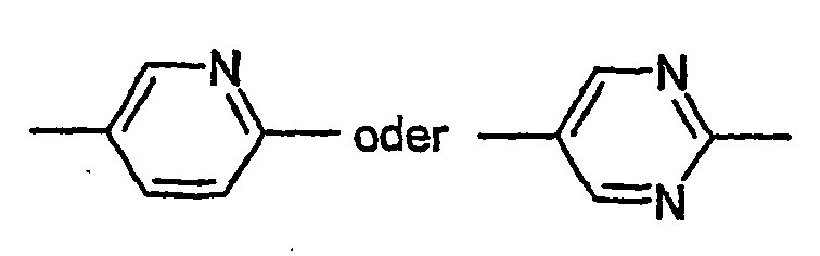
- Z11 und Z12
- jeweils voneinander unabhängig, eine Einfachbindung, -CO-O-, trans -CH=CH-, -CH=CF-, -CF=CH-, -CF=CF-, -CH=CH-CO-O-, -CF=CF-CO-O-, -CF=CH-CO-O-, -CH=CF-CO-O-, -CF2-O-, -O-CF2- oder -C=C- oder eine Kombination von zwei oder mehreren dieser Gruppen, bevorzugt mindestens eine dieser Gruppen -COO- oder -CF2-O-,
- X1
- F, Cl, NO2, -OCF3, -CF3, -OCF2H, Cl, CN, -C≡C-CN oder NCS, bevorzugt CN, -CF3, -C≡C-CN oder NCS, besonders bevorzugt CN oder -CF3,
- Y11, Y12, Y13 und Y14,
- jeweils unabhängig voneinander, H oder F und
- n1
- 0 oder 1, bevorzugt 0 bedeuten,

- R2
- Alkyl oder Alkoxy mit 1 bis 7 C-Atomen, Alkenyl, Alkenyloxy
oder Oxaalkyl mit 2 bis 7 C-Atomen, bevorzugt Alkyl oder Alkoxy mit 1 bis 5 C-Atomenoder Alkenyl mit 2 bis 5 C-Atomen, bevorzugt Alkyl oder Alkoxy,


- Z21 und Z22
- jeweils voneinander unabhängig, eine Einfachbindung, -CO-O-, trans -CH=CH-, -CH=CF-, -CF=CH-, -CF=CF-, -CH=CH-CO-O-, -CF=CF-CO-O-, -CF=CH-CO-O-, -CH=CF-CO-O-, -CF2-O-, -O-CF2- oder -C≡C- oder eine Kombination von zwei oder mehreren dieser Gruppen, bevorzugt mindestens eine dieser Gruppen -COO- oder -CF2-O-,
- X2
- F, Cl, NO2, -OCF3, -CF3, -OCF2H, Cl, CN, -C≡C-CN oder NCS, bevorzugt CN, -CF3, -C≡C-CN oder NCS, besonders bevorzugt CN,
- Y2
- H oder F und
- n2
- 0 oder 1 bedeuten.
- R 1
- Alkyl having 1 to 7 C atoms or oxaalkyl having 2 to 7 C atoms, in each case preferably having 2 to 5 C atoms, preferably alkyl,
- Z 11 and Z 12
- each independently, a single bond, -CO-O-, trans -CH = CH-, -CH = CF-, -CF = CH-, -CF = CF-, -CH = CH-CO-O-, -CF = CF-CO-O-, -CF = CH-CO-O-, -CH = CF-CO-O-, -CF 2 -O-, -O-CF 2 - or -C = C- or a combination of two or more of these groups, preferably at least one of these groups -COO- or -CF 2 -O-,
- X 1
- F, Cl, NO 2 , -OCF 3 , -CF 3 , -OCF 2 H, Cl, CN, -C≡C-CN or NCS, preferably CN, -CF 3 , -C≡C-CN or NCS, especially preferably CN or -CF 3 ,
- Y 11 , Y 12 , Y 13 and Y 14 ,
- each independently, H or F and
- n 1
- 0 or 1, preferably 0,
- R 2
- Alkyl or alkoxy having 1 to 7 C atoms, alkenyl, alkenyloxy or oxaalkyl having 2 to 7 C atoms, preferably alkyl or alkoxy having 1 to 5 C atoms or alkenyl having 2 to 5 C atoms, preferably alkyl or alkoxy,
- Z 21 and Z 22
- each independently, a single bond, -CO-O-, trans -CH = CH-, -CH = CF-, -CF = CH-, -CF = CF-, -CH = CH-CO-O-, -CF = CF-CO-O-, -CF = CH-CO-O-, -CH = CF-CO-O-, -CF 2 -O-, -O-CF 2 - or -C≡C- or a combination of two or more of these groups, preferably at least one of these groups -COO- or -CF 2 -O-,
- X 2
- F, Cl, NO 2 , -OCF 3 , -CF 3 , -OCF 2 H, Cl, CN, -C≡C-CN or NCS, preferably CN, -CF 3 , -C≡C-CN or NCS, especially prefers CN,
- Y 2
- H or F and
- n 2
- 0 or 1 mean.
In einer bevorzugten Ausführungsform der vorliegenden Anmeldung enthalten die Medien eine oder mehrere Verbindungen der Formel I und bestehen bevorzugt überwiegend und besonders bevorzugt nahezu vollständig aus einer oder mehreren Verbindungen der Formel IIn a preferred embodiment of the present application, the media contain one or more compounds of the formula I and preferably consist predominantly and particularly preferably almost completely of one or more compounds of the formula I.
Bevorzugt werden die Verbindungen der Formel I ausgewählt aus der Gruppe der Verbindungen I-1 und I-2


- R1
- Alkyl mit 1 bis 7, bevorzugt mit 1 bis 5, bevorzugt bis 3 C-Atomen,
- Z12
- -COO- oder -CF2-O- und
- X1
- CN, -CF3 oder NCS, bevorzugt CN oder -CF3
- R 1
- Alkyl with 1 to 7, preferably with 1 to 5, preferably up to 3 C atoms,
- Z 12
- -COO- or -CF 2 -O- and
- X 1
- CN, -CF 3 or NCS, preferably CN or -CF 3
Besonders bevorzugt enthalten die erfindungsgemäßen Medien eine oder mehrere Verbindungen der Formel I, bevorzugt der Formel I-1 und/oder der Formel I-2, worin X1 CF3 bedeutet.The novel media particularly preferably contain one or more compounds of the formula I, preferably of the formula I-1 and / or of the formula I-2, in which X 1 is CF 3 .
Bevorzugt werden die Verbindungen der Formel II ausgewählt aus der Gruppe der Verbindungen II-1 bis II-7
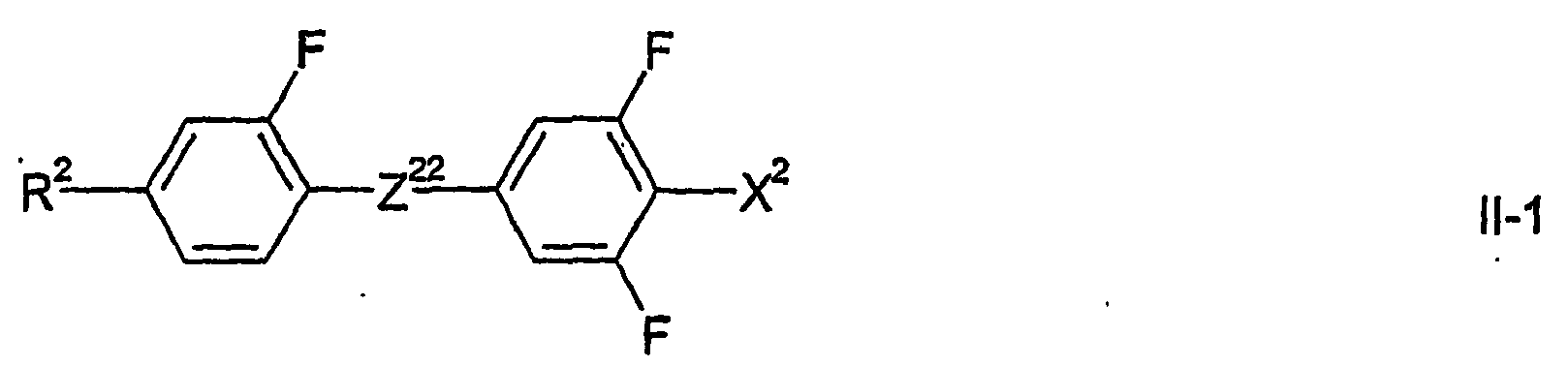


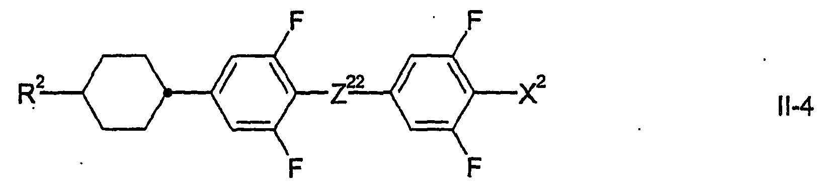


- R2
- Alkyl oder Alkoxy mit 1 bis 7 C-Atomen, Alkenyl, Alkenyloxy
oder Oxaalkyl mit 2 bis 7 C-Atomen, bevorzugt Alkyl oder Alkoxy mit 1 bis 5 C-Atomen, - Z22
- eine Einfachbindung, -CO-O- oder -CF2-O- bevorzugt -COO- oder -CF2-O-,
bei Formel II-6 auch, besonders bevorzugt, -CsC- und - X 2
- CN, oder CF3, bevorzugt CF3,
bei Formel II-6 besonders bevorzugt CN, oder CF3, bevorzugt CN
- R 2
- Alkyl or alkoxy having 1 to 7 C atoms, alkenyl, alkenyloxy or oxaalkyl having 2 to 7 C atoms, preferably alkyl or alkoxy having 1 to 5 C atoms,
- Z 22
- a single bond, -CO-O- or -CF 2 -O-, preferably -COO- or -CF 2 -O-,
in formula II-6 also, more preferably, -CsC- and - X 2
- CN, or CF 3 , preferably CF 3 ,
in the case of formula II-6, particularly preferably CN, or CF 3 , preferably CN
Bevorzugt enthalten die erfindungsgemäßen Medien eine oder mehrere Verbindungen ausgewählt aus der Gruppe der Verbindungen der Formeln II1 bis II-5, bevorzugt Verbindungen worin Z22-CO-O- bedeutet.The media according to the invention preferably comprise one or more compounds selected from the group of the compounds of the formulas II1 to II-5, preferably compounds in which Z 22 is -CO-O-.
In einer bevorzugten Ausführungsform der vorliegenden Erfindung enthält die Komponente A der erfindungsgemäßen Medien bevorzugt eine oder mehrere Verbindungen der Formel II und besteht besonders bevorzugt überwiegend und ganz besonders bevorzugt nahezu vollständig aus einer oder mehreren Verbindungen der Formel II.In a preferred embodiment of the present invention, component A of the media according to the invention preferably contains one or more compounds of the formula II and particularly preferably consists predominantly and very particularly preferably almost completely of one or more compounds of the formula II.
Für die Lichtsteuerelemente gemäß der vorliegenden Erfindung können sowohl mesogene Steuermedien verwendet werden, die in der Mesophase, bevorzugt in der nematischen Phase, eine positive dielektrische Anisotropie (Δε) aufweisen, als auch solche die eine negative dielektrische Anisotropie aufweisen. Bevorzugt werden mesogene Steuermedien verwendet, die in der Mesophase eine positive dielektrische Anisotropie (Δε) aufweisen. Wenn die mesogenen Steuermedien eine positive dielektrische Anisotropie haben, hat diese bei den Steuermedien, die eine Übergang von der nematischen Phase oder von der cholesterischen Phase in die isotrope Phase aufweisen, bei 1 kHz und einer Temperatur von 4° unterhalb des Klärpunkts bzw. unterhalb T(N*,BP), bevorzugt in der nematischen Phase, bevorzugt einen Wert von 40 oder mehr.For the light control elements according to the present invention, both mesogenic control media can be used, which in the mesophase, preferably in the nematic phase, a positive have dielectric anisotropy (Δε), as well as those which have a negative dielectric anisotropy. Preference is given to using mesogenic control media which have a positive dielectric anisotropy (Δε) in the mesophase. When the mesogenic control media has a positive dielectric anisotropy, it has a control frequency at 1 kHz and a temperature of 4 ° below the clearing point and below T, respectively, at the control media having a nematic or cholesteric phase to isotropic phase transition (N *, BP), preferably in the nematic phase, preferably 40 or more.
Die mesogenen Medien gemäß der vorliegenden Erfindung mit positiver dielektrischer Anisotropie bestehen besonders bevorzugt überwiegend und ganz besonders bevorzugt nahezu vollständig aus der Komponente A.The mesogenic media according to the present invention having positive dielectric anisotropy particularly preferably consists predominantly, and most preferably almost completely, of component A.
In einer bevorzugten Ausführungsform enthalten die mesogenen Medien gemäß der vorliegenden Erfindung mit positiver dielektrischer Anisotropie eine oder mehrere Komponenten ausgewählt aus der Gruppe der Komponenten B bis D, bevorzugt ausgewählt aus der Gruppe der Komponenten B und D, besonders bevorzugt der Komponente B.In a preferred embodiment, the mesogenic media according to the present invention having positive dielectric anisotropy contain one or more components selected from the group of components B to D, preferably selected from the group of components B and D, particularly preferably component B.
Die mesogenen Medien gemäß der vorliegenden Erfindung mit positiver dielektrischer Anisotropie enthalten bevorzugt
- 5% bis 80%, bevorzugt 10% bis 60%, besonders bevorzugt 18% bis 43% einer oder mehrerer Verbindungen der Formel l,
- 5% bis 95%, bevorzugt 15% bis 80%, besonders bevorzugt 40% bis 70% einer oder mehrerer Verbindungen der Formel II und
- 0% bis 30% bevorzugt 0% bis 15%, besonders bevorzugt 0% bis 10% einer oder mehrerer weiterer Verbindungen.
- From 5% to 80%, preferably from 10% to 60%, particularly preferably from 18% to 43% of one or more compounds of the formula I,
- 5% to 95%, preferably 15% to 80%, particularly preferably 40% to 70% of one or more compounds of the formula II and
- 0% to 30% preferably 0% to 15%, particularly preferably 0% to 10% of one or more further compounds.
Die mesogenen Medien gemäß der vorliegenden Erfindung mit positiver dielektrischer Anisotropie enthalten bevorzugt
- 3% bis 45%, bevorzugt 5% bis 40%, besonders bevorzugt 10% bis 35% einer oder mehrerer Verbindungen der Formel I-1 und/oder
- 2% bis 35%, bevorzugt 4% bis 30%, besonders bevorzugt 5% bis 30% einer oder mehrerer Verbindungen der Formel I-1 und/oder
- 0 bis 30%, bevorzugt 2% bis 25%, besonders bevorzugt 5% bis 20% einer oder mehrerer Verbindungen der Formel II-1 und/oder
- 0 bis 30%, bevorzugt 2% bis 25%, besonders bevorzugt 5% bis 20% einer oder mehrerer Verbindungen der Formel II-2 und/oder
- 5% bis 70%, bevorzugt 15% bis 65%, besonders bevorzugt 20% bis 60% einer oder mehrerer Verbindungen der Formel II-3 und/oder II-4, bevorzugt II-4 und/öder
- 0% bis 20% bevorzugt 0% bis 15%, besonders bevorzugt 3% bis 12% einer oder mehrerer Verbindungen der Formel II-5 und/oder
- 0% bis 30% bevorzugt 0% bis 20%, besonders bevorzugt 3% bis 15% einer oder mehrerer Verbindungen der Formel II-6 und/oder
- 0% bis 35% bevorzugt 0% bis 30%, besonders bevorzugt 3% bis 12% einer oder mehrerer Verbindungen der Formel II-7.
- 3% to 45%, preferably 5% to 40%, particularly preferably 10% to 35% of one or more compounds of the formula I-1 and / or
- 2% to 35%, preferably 4% to 30%, particularly preferably 5% to 30% of one or more compounds of the formula I-1 and / or
- 0 to 30%, preferably 2% to 25%, particularly preferably 5% to 20% of one or more compounds of the formula II-1 and / or
- 0 to 30%, preferably 2% to 25%, particularly preferably 5% to 20% of one or more compounds of the formula II-2 and / or
- 5% to 70%, preferably 15% to 65%, particularly preferably 20% to 60% of one or more compounds of the formula II-3 and / or II-4, preferably II-4 and / or
- 0% to 20% preferably 0% to 15%, particularly preferably 3% to 12% of one or more compounds of the formula II-5 and / or
- 0% to 30% preferably 0% to 20%, particularly preferably 3% to 15% of one or more compounds of formula II-6 and / or
- 0% to 35% preferably 0% to 30%, particularly preferably 3% to 12% of one or more compounds of the formula II-7.
Die mesogenen Medien gemäß der vorliegenden Erfindung mit negativer dielektrischer Anisotropie bestehen besonders bevorzugt überwiegend und ganz besonders bevorzugt nahezu vollständig aus der Komponente D.The mesogenic media according to the present invention having negative dielectric anisotropy particularly preferably consists predominantly, and most preferably almost completely, of component D.
Die Komponente D dieser Medien enthält bevorzugt eine oder mehrere Verbindungen.Component D of these media preferably contains one or more compounds.
Die mesogenen Medien mit negativer dielektrischer Anisotropie gemäß der vorliegenden Erfindung enthalten bevorzugt
- eine Komponente A' bestehend aus einer oder mehreren Verbindungen mit einer stark negativen dielektrischen Anisotropie von -5 oder weniger,
- optional eine Komponente B' bestehend aus einer oder mehreren Verbindungen mit einer moderat negativen dielektrischen Anisotropie von -1,5 bis < -5,
- optional eine Komponente C' bestehend aus einer oder mehreren dielektrisch neutralen Verbindungen mit einer dielektrischen Anisotropie von -1,5 bis +1,5 und
- gegebenenfalls eine Komponente D' bestehend aus einer oder mehreren Verbindungen mit einer positiven dielektrischen Anisotropie von mehr als 1,5.
- a component A 'consisting of one or more compounds with a strongly negative dielectric anisotropy of -5 or less,
- optionally a component B 'consisting of one or more compounds with a moderately negative dielectric anisotropy of -1.5 to <-5,
- optionally a component C 'consisting of one or more dielectrically neutral compounds having a dielectric anisotropy of -1.5 to +1.5 and
- optionally a component D 'consisting of one or more compounds having a positive dielectric anisotropy greater than 1.5.
Das mesogene Medium gemäß der vorliegenden Erfindung kann weitere Additive und chirale Dotierstoffe in üblichen Konzentrationen enthalten. Die Gesamtkonzentration dieser weiteren Bestandteile liegt im Bereich von 0% bis 10%, bevorzugt im Bereich von 0, 1 % bis 6%, bezogen auf die Gesamtmischung. Die Konzentrationen der einzelnen dieser Verbindungen liegen im Bereich von 0,1 bis 3%. Die Konzentration dieser Verbindungen und ähnlicher Bestandteile der Mischung werden, mit Ausnahme der chiralen Dotierstoffe bei den Medien die eine Blaue Phase aufweisen, bei der Angabe der Konzentrationsbereiche der übrigen Mischungsbestandteile nicht berücksichtigt.The mesogenic medium according to the present invention may contain further additives and chiral dopants in usual concentrations. The total concentration of these other ingredients is in the range of 0% to 10%, preferably in the range of 0, 1% to 6%, based on the total mixture. The concentrations of each of these compounds are in the range of 0.1 to 3%. The concentration of these compounds and similar components of the mixture, with the exception of the chiral dopants in the media which have a blue phase, are not taken into account in the indication of the concentration ranges of the remaining mixture components.
Die Medien werden auf übliche Weise aus den Verbindungen erhalten. Zweckmäßiger Weise werden die Verbindungen die in geringerer Menge eingesetzt werden in den in größerer Menge eingesetzten Verbindungen gelöst. Wird die Temperatur während des Mischvorgangs über den Klär punkt der überwiegenden Komponente erhöht, kann die Vollständigkeit der Auflösung leicht beobachtet werden. Die erfindungsgemäßen Medien können jedoch auch auf andere Weisen hergestellt werden. So durch den Einsatz von Vormischungen. Als Vormischungen könne unter anderem Homologenmischungen und/oder eutektische Mischungen eingesetzt werden. Die Vormischungen können aber auch bereits selbst einsatzfähige Medien sein. Dies ist bei sogenannten Zwei- oder Mehr-Flaschen-Systemen.(Englisch: "two-bottle" oder "multi-bottle systems") der Fall.The media are obtained from the compounds in the usual way. Conveniently, the compounds which are used in lesser amounts are dissolved in the compounds used in larger quantities. If the temperature during the mixing process above the Klär point of the predominant component increases, the completeness of the resolution can be easily observed. However, the media according to the invention can also be prepared in other ways. So by the use of premixes. As premixes, inter alia, homolog mixtures and / or eutectic mixtures can be used become. The premixes can also be self-usable media. This is the case with so-called two-bottle or multi-bottle systems ("two-bottle" or "multi-bottle systems").
In der vorliegenden Anmeldung gilt, soweit nicht explizit anders angegeben, das Folgende.Unless otherwise stated, the following applies in the present application.
Die angegebenen Bereiche von Werten schließen bevorzugt die Grenzwerte ein.The specified ranges of values preferably include the limits.
Die Konzentrationen sind in Massen-% gegeben und beziehen sich auf die vollständige Mischung. Temperaturen sind in Grad Celsius und Temperaturdifferenzen in Differenzgrad Celsius angegeben. Alle physikalischen Eigenschaften wurden bestimmt wie in "Merck Liquid Crystals, Physical Properties of Liquid Crystals", Stand Nov. 1997, Merck KGaA, Deutschland und sind für eine Temperatur von 20 °C gegeben, sofern nicht explizit anders angegeben. Die optische Anisotropie (Δn), auch Doppelbrechung genannt, wird bei einer Wellenlänge von 589,3 nm bestimmt. Die dielektrischen Eigenschaften werden bei einer Frequenz von 1 kHz bestimmt.The concentrations are given in mass% and refer to the complete mixture. Temperatures are given in degrees Celsius and temperature differences in degrees Celsius. All physical properties were determined as in "Merck Liquid Crystals, Physical Properties of Liquid Crystals", as of Nov. 1997, Merck KGaA, Germany and are given for a temperature of 20 ° C, unless explicitly stated otherwise. The optical anisotropy (Δn), also called birefringence, is determined at a wavelength of 589.3 nm. The dielectric properties are determined at a frequency of 1 kHz.
Im Zusammenhang mit Angaben zur Zusammensetzung der Medien, bzw. ihrer Komponenten, bedeutet
- "enthalten", dass die Konzentration des jeweiligen genannten Materials, also der Komponente oder der Verbindung, in der Bezugseinheit, also dem Medium bzw. der Komponente, bevorzugt 10% oder mehr, besonders bevorzugt 20 % oder mehr und ganz besonders bevorzugt 30% oder mehr beträgt,
- "überwiegend bestehen aus", dass die Konzentration des genannten Materials in der Bezugseinheit bevorzugt 50% oder mehr, besonders bevorzugt 60 % oder mehr und ganz besonders bevorzugt 70% oder mehr beträgt und
- "nahezu vollständig bestehen aus", dass die Konzentration des genannten Materials in der Bezugseinheit bevorzugt 80% oder mehr, besonders bevorzugt 90 % oder mehr und ganz besonders bevorzugt 95% oder mehr beträgt.
- "contain" that the concentration of the respective said material, so the component or the compound in the reference unit, so the medium or the component, preferably 10% or more, more preferably 20% or more and most preferably 30% or is more,
- "predominantly consist of" that the concentration of said material in the reference unit is preferably 50% or more, more preferably 60% or more and most preferably 70% or more, and
- "Almost complete" means that the concentration of said material in the reference unit is preferably 80% or more, more preferably 90% or more, and most preferably 95% or more.
Dielektrisch positive Verbindungen haben ein Δε > 1,5, dielektrisch neutrale Verbindungen haben ein Δε im Bereich -1,5 ≤ Δε ≤ 1,5 und dielektrisch negative Verbindungen haben ein Δε < -1,5. Die selben Definitionen gelten auch für Komponenten von Mischungen und für Mischungen.Dielectric positive compounds have a Δε> 1.5, dielectrically neutral compounds have a Δε in the range -1.5 ≤ Δε ≤ 1.5 and dielectrically negative compounds have a Δε <-1.5. The same definitions apply to components of mixtures and mixtures.
Die dielektrischen Eigenschaften, elektrooptischen Eigenschaften (z.B. die Schwellenspannungen) und die Schaltzeiten wurden in bei der Merck KGaA, Darmstadt, Deutschland hergestellten Testzellen, bestimmt. Die Testzellen zur Bestimmung von Δε hatten eine Schichtdicke von 22 µm und eine kreisförmige Elektrode aus Indiumzinnoxid (ITO)-mit einer Fläche von 1,13 cm2 und einem Schutzring. Für homeotrope Orientierung zu Bestimmung von ε∥ wurden Zellen mit einer homeotrop orientierenden Polyimid-Orientierungsschicht verwendet. Alternativ kann Lezithin (Merck KGaA) als. Orientierungsmittel verwendet. Die Zellen zur Bestimmung von ε⊥ hatten Orientierungsschichten aus dem Polyimid AL-1054 der Firma Japan Synthetic Rubber, Japan. Die Kapazitäten wurden in der Regel mit einem Frequenzanalysator Solatron 1260 mit einer Rechteckwelle mit einer Effektivspannung von 0.3 Vrms gemessen. Die elektooptischen Untersuchungen wurden mit weißem Licht durchgeführt. Die charakteristischen Spannungen wurden unter senkrechter Beobachtung bestimmt.Dielectric properties, electro-optic properties (eg threshold voltages) and switching times were determined in test cells made by Merck KGaA, Darmstadt, Germany. The test cells for determining Δε had a layer thickness of 22 μm and a circular electrode made of indium tin oxide (ITO) with an area of 1.13 cm 2 and a guard ring. For homeotropic orientation to determine ε∥, cells with a homeotropically orienting polyimide alignment layer were used. Alternatively, lecithin (Merck KGaA) may be used as a. Orientation agent used. The cells for the determination of ε ⊥ had orientation layers of the polyimide AL-1054 from Japan Synthetic Rubber, Japan. Capacities were typically measured with a Solatron 1260 frequency analyzer with a square wave with an effective voltage of 0.3 V rms . The electrophotographic examinations were performed with white light. The characteristic stresses were determined under vertical observation.
Die dielektrischen Eigenschaften der Materialien werden bei 1.kHz und 20°C, sowie für Steuermedien, die einen Übergang von der nematischen Phase oder der cholesterischen Phase in die isotrope Phase (T(N,I)) aufweisen, bei einer Temperatur von 4° unterhalb sowie bei einer Temperatur von 4° oberhalb des Klärpunkts (T(N,I) bzw. T(N*,I)) wieder jeweils bei 1 kHz, und bei Steuermedien, die einen Übergang von der Blauen Phase in die isotrope Phase aufweisen bei einer.Temperatur von 4° oberhalb der entsprechenden Übergangstemperatur (T(N*,BP)) des jeweiligen Materials, hier allerdings bei 30 Hz, bestimmt.The dielectric properties of the materials are at 1.kHz and 20 ° C, as well as control media having a transition from the nematic or cholesteric phase to the isotropic phase (T (N, I)) at a temperature of 4 ° below and at a temperature of 4 ° above the clearing point (T (N, I) or T (N *, I)) again at 1 kHz, respectively, and control media having a transition from the blue phase to the isotropic phase at a temperature of 4 ° above the corresponding transition temperature (T (N *, BP)) of the respective material, but here at 30 Hz.
Die dielektrische Anisotropie (Δε) der Verbindungen wird durch Extrapolation der Werte einer 10%-igen Lösung der jeweiligen Verbindung in einer Wirtsmischung bei 20°C auf einen Anteil der jeweiligen Verbindung von 100% bestimmt. Die Kapazitäten der Testmischungen werden sowohl in einer Zelle mit homeotroper, als auch in einer Zelle mit homogener Randorientierung bestimmt. Die Schichtdicke beider Zellentypen beträgt ca. 20 µm. Zur Messung wird eine Rechteckwelle mit einer Frequenz von 1 kHz und einer effektiven Spannung (rms, Englisch: root mean square) von typischer Weise 0,2 V bis 1,0 V verwendet. In jedem Fall ist die verwendete Spannung niedriger als die kapazitive Schwelle der jeweils untersuchten Mischung.The dielectric anisotropy (Δε) of the compounds is determined by extrapolation of the values of a 10% solution of the respective compound in a host mixture at 20 ° C. to a proportion of the respective compound of 100%. The capacities of the test mixtures are determined both in a cell with homeotropic and in a cell with homogeneous boundary orientation. The layer thickness of both cell types is approximately 20 μm. For measurement, a square wave with a frequency of 1 kHz and an effective voltage (rms, English: root mean square) of typically 0.2 V to 1.0 V is used. In any case, the voltage used is lower than the capacitive threshold of each tested mixture.
Für dielektrisch positive Verbindungen wird die Mischung ZLI-4792 und für dielektrisch neutrale, sowie für dielektrisch negative Verbindungen, die Mischung ZLI-3086, beide von Merck KGaA, Deutschland, als Wirtsmischung verwendet. Diese Wirtsmischungen werden auch für Komponenten und Medien verwendet, die selbst bei der betreffenden Temperatur keine nematische Phase aufweisen, bzw. die nicht bis zu der betreffenden Temperatur in der nematischen Phase unterkühlt werden können. Ist die Löslichkeit der Verbindungen, Komponenten oder Medien in der jeweiligen Wirtsmischung geringer als 10%, wird ausnahmsweise die Konzentration der untersuchten Substanz auf 5% erniedrigt. Ist die Löslichkeit einer dielektrisch positiven Substanz (einer Verbindung, einer Komponente eines Mediums oder eines Mediums) in der Wirtsmischung ZLI-4792 geringer als 5%, so wird die nematische Mischung MLC-6828, Merck KGaA, Deutschland als Wirtsmischung verwendet. Auch hier wird nötigenfalls die Konzentration der zu untersuchenden Substanz von 10% auf 5% halbiert. Aus der Änderung der Werte gegenüber denen der Wirtsmischung wird auf den Wert der reinen Substanz extrapoliert.For dielectrically positive compounds, the mixture ZLI-4792 and for dielectrically neutral as well as for dielectrically negative compounds, the mixture ZLI-3086, both from Merck KGaA, Germany, is used as the host mixture. These host mixtures are also used for components and media that have no nematic phase even at the temperature in question, or that can not be subcooled up to the relevant temperature in the nematic phase. If the solubility of the compounds, components or media in the respective host mixture is less than 10%, the concentration of the substance investigated is exceptionally lowered to 5%. If the solubility of a dielectrically positive substance (a compound, a component of a medium or a medium) in the host mixture ZLI-4792 is less than 5%, the nematic mixture MLC-6828, Merck KGaA, Germany is used as the host mixture. Again, if necessary, the concentration of the substance to be examined is halved from 10% to 5%. The change in the values from those of the host mixture is extrapolated to the value of the pure substance.
Die erdfindungsgemäßen Medien enthalten bevorzugt 0% bis 10% an Verbindungen deren Löslichkeit in der entsprechenden Wirtsmischung (ZLI-3086 bzw. MLC-6828) geringer als 5% ist. Bevorzugt ist die Konzentration dieser Verbindungen 8% oder weniger, besonders bevorzugt 5% oder weniger und ganz besonders bevorzugt 4% oder weniger.The media according to the invention preferably contain 0% to 10% of compounds whose solubility in the corresponding host mixture (ZLI-3086 or MLC-6828) is less than 5%. Preferably, the concentration of these compounds is 8% or less, more preferably 5% or less and most preferably 4% or less.
Die dielektrische Anisotropie der Verbindungen, Komponenten und gegebenenfalls der Medien, die bei 20°C oder bei einer Temperatur von 4° unterhalb ihres Klärpunkts (T(N,I) bzw. (T(N*,I) bzw. Ihrer Übergangstemperatur (T(N*,BP)) nicht in der nematischen Phase vorliegen, bzw. die nicht bis zu dieser Temperatur in dieser Phase unterkühlbar sind, werden aus einer Wirtsmischung bestimmt, wie oben bei den Verbindungen beschrieben.The dielectric anisotropy of the compounds, components and optionally the media, which are at 20 ° C or at a temperature of 4 ° below their clearing point (T (N, I) or (T (N *, I) or their transition temperature (T (N *, BP)) are not present in the nematic phase, or that can not be supercooled up to this temperature in this phase, are determined from a host mixture, as described above for the compounds.
Die Dielektrizitätskonstanten ε∥ und ε⊥ werden mit einer absoluten Genauigkeit von ca. +/-0,1 bis +/-0,2 bestimmt, wodurch sich für die dielektrische Anisotropie (Δε) eine absoluten Genauigkeit von ca. +/-0,2 bis +/-0,4, typischerweise von +/-0,3 ergibt. Die Genauigkeit nimmt bei größeren Werten ab, die möglichen Abweichungen nehmen also zu. Bei Werten von Δε von 25 bis 40 beträgt die absolute Genauigkeit ca. +/-0,5 und bei Werten von mehr als 40 beträgt die absolute Genauigkeit ca. +/-1,0.The dielectric constants ε∥ and ε ⊥ are determined with an absolute accuracy of approx. +/- 0.1 to +/- 0.2, which results in an absolute accuracy of approx. +/- 0 for the dielectric anisotropy (Δε). 2 to +/- 0.4, typically of +/- 0.3. The accuracy decreases with larger values, so the possible deviations increase. At values of Δε of 25 to 40, the absolute accuracy is about +/- 0.5, and for values of more than 40, the absolute accuracy is about +/- 1.0.
Die dielektrische Suszeptibilität der Medien wird bei einer Temperatur von 4° oberhalb der Temperatur ihres Übergangs in die optisch isotrope Phase in der optisch isotropen Phase bestimmt. Sie wird mittlere dielektrische Suszeptibilität (εav.) genannt. Bei den Medien, die einen Übergang aus der nematischen Phase oder der cholesterischen Phase in die isotrope Phase aufweisen, kann sie auch, in erster Näherung, aus der Extrapolation der mittleren dielektrischen Suszeptibilität des nematischen Mediums über den Übergangspunkt in die optisch isotrope Phase hinaus erhalten werden. Die dielektrische Suszeptibilität der Medien wird typischer weise mit einer absoluten Genauigkeit von ca. +/-0,1 bis +/-0,2 bestimmt. Bei großen Werten der dielektrischen Suszeptibilität, von 30 oder mehr, beträgt die absolute Genauigkeit ca. +/-0,5 und bei sehr großen Werten, von 40 oder mehr oder sogar von 60 oder mehr, beträgt die absolute Genauigkeit ca. +/-1.The dielectric susceptibility of the media is determined at a temperature of 4 ° above the temperature of their transition to the optically isotropic phase in the optically isotropic phase. It is called average dielectric susceptibility (ε av. ). In the case of the media which have a transition from the nematic phase or the cholesteric phase to the isotropic phase, it can also be obtained, to a first approximation, from the extrapolation of the average dielectric susceptibility of the nematic medium beyond the transition point into the optically isotropic phase , The dielectric susceptibility of the media is typically determined with an absolute accuracy of about +/- 0.1 to +/- 0.2. For large values of dielectric susceptibility, of 30 or more, the absolute accuracy is about +/- 0.5, and for very large values, of 40 or more, or even 60 or more, the absolute accuracy is about +/- 1.
Für die Steuermedien, die einen Übergang aus der nematischen Phase oder der cholesterischen Phase in die isotrope Phase aufweisen, wurde die Klärenthalpie per "differential scanning calorimetry", kurz DSC bestimmt. Hierzu wurde ein kommerzielles Gerät DSC2920 der Firma Texas Instruments, USA verwendet. Es wurden 2 mg bis 8 mg, typischerweise 4 mg, des betreffenden Materials in einem Pfännchen gegen ein leeres Pfännchen als Referenz vermessen. Dabei wurde die Temperatur mit einer Heizrate von 10 Grad/Minute erhöht. Der Startpunkt wurde ca. 30° bis 40° unterhalb des Klärpunkts der Substanz gewählt. Der Endpunkt lag jeweils ca. 30° oberhalb des Klärpunkts der Substanz. Die relative Genauigkeit der Werte beträgt jeweils ca. +/-10% bis +/-15%. Bei sehr kleinen Werten der Klärenthalpie muß gegebenenfalls die Probenmenge erhöht oder auf ein präziseres Meßgerät gewechselt werden.For the control media, which have a transition from the nematic phase or the cholesteric phase to the isotropic phase, the enthalpy of clarification was determined by differential scanning calorimetry, DSC for short certainly. For this purpose, a commercial device DSC2920 Texas Instruments, USA was used. 2 mg to 8 mg, typically 4 mg, of the material in question were measured in a pan against an empty pan as a reference. The temperature was increased at a heating rate of 10 degrees / minute. The starting point was chosen about 30 ° to 40 ° below the clearing point of the substance. The end point was in each case about 30 ° above the clearing point of the substance. The relative accuracy of the values is approx. +/- 10% to +/- 15%. For very small values of the enthalpy of clarification, it may be necessary to increase the sample volume or change it to a more precise measuring instrument.
Der Wert der Doppelbrechung der erfiridungsgemäßen Medien wird hier in der riematischen Phase bei 20°C und bei einer Temperatur von 4° unterhalb des Klärpunkts bzw. der Übergangstemperatur T(N*,BP) gemessen. Ist das Medium bei einer dieser beiden Temperaturen oder bei diesen beiden Temperaturen nicht stabil nematisch oder zumindest bis zu dieser Temperatur in der nematischen Phase unterkühlbar, so wird die Doppelbrechung einer Mischung aus der entsprechenden nematischen Wirtsmischung extrapoliert, wie oben bei der Bestimmung der dielektrischen Anisotropie beschrieben.The value of the birefringence of the erfiridungsgemäßen media is measured here in the Riematischen phase at 20 ° C and at a temperature of 4 ° below the clearing point or the transition temperature T (N *, BP). If the medium at one of these two temperatures or at these two temperatures is not stable nematic or at least supercoolable up to this temperature in the nematic phase, the birefringence of a mixture of the corresponding nematic host mixture is extrapolated, as described above in the determination of the dielectric anisotropy ,
Ist der cholesterische Pitch der erfindungsgemäßen Medien zu kurz um eine Bestimmung der anisotropen Eigenschaften wie z.B. der Doppelbrechung oder der dielektrischen Suzeptibilität zu erlauben stehen hierfür drei Möglichkeiten zur Verfügung. Die erste, am meisten bevorzugte Möglichkeit ist der Ersatz der bzw. aller der in den Medien verwendeten chiralen Verbindungen durch deren Racemat. Die zweite ebenfalls noch bevorzugte Möglichkeit ist die Verringerung der Konzentration der chiralen Verbindung, bzw. der chiralen Verbindungen auf einen Wert der den cholesterischen Pitch so groß werden lässt, dass die Bestimmung der Eigenschaften gerade möglich wird. Die dritte, am wenigsten bevorzugte Möglichkeit ist die Kompensation des cholesterischen Pitchs durch Zugabe eine chiralen Verbindung mit umgekehrtem Helixdrehsinn. Hierzu wird bevorzugt die entsprechenden Verbindung des Eantiomerenpaares R-8011 und S-8011 der Fa. Merck KGaA verwendet.If the cholesteric pitch of the media according to the invention is too short to allow a determination of the anisotropic properties, for example birefringence or dielectric susceptibility, three options are available for this purpose. The first, most preferred option is the replacement of the or each of the chiral compounds used in the media by their racemate. The second possibility, which is also preferred, is to reduce the concentration of the chiral compound or chiral compounds to a value which makes the cholesteric pitch so large that the determination of the properties becomes possible. The third, least preferred option is to compensate for the cholesteric pitch by adding a chiral compound with reverse helix rotation. For this purpose, it is preferred to use the corresponding compound of the E-romantiomers R-8011 and S-8011 from Merck KGaA.
Der Begriff Schwellenspannung bedeutet in der vorliegenden Anmeldung die optische Schwelle und wird für einen relativen Kontrast von 10 % (V10) angegeben. Die Mittgrauspannung und die Sättigungsspannung werden ebenfalls optisch bestimmt und für einen relativen Kontrast von 50%, bzw. von 90 % angegeben. Als Bezugsgröße und charakteristischer Wert der elektrooptischen Kennlinie der verschiedenen Medien wird in der vorliegenden Anmeldung in der Regel die Spannung (V70) angegeben bei der die Kennlinie zum ersten Mal den Wert von 70% relativem Kontrast erreicht. Wird die kapazitive Schwellenspannung (V0), auch Freedericksz-Schwelle genannt, angegeben, so ist dies explizit vermerkt.The term threshold voltage in the present application means the optical threshold and is given for a relative contrast of 10% (V 10 ). The midgrain voltage and the saturation voltage are also optically determined and given for a relative contrast of 50% and 90%, respectively. As a reference value and characteristic value of the electro-optical characteristic of the various media in the present application usually the voltage (V 70 ) is specified at which the characteristic reaches the value of 70% relative contrast for the first time. If the capacitive threshold voltage (V 0 ), also called Freedericksz threshold, specified, this is explicitly noted.
Die,Medien wurden in Testzellen mit interdigitalen Elektroden gefüllt. Die Schichtdicke der Testzellen betrug in der Regel ca. 10 µm. Die Breite der Elektroden betrug 10 µm und der Anstand zwischen den benachbarten Elektroden betrug 15 µm. Die elektrooptische Kennlinie wurde bei einer Temperatur von 2° oberhalb des Klärpunkts (T(N,I) bzw. T(N*,I)) bzw. der Übergangstemperatur von der cholesterischen Phase in die Blauen Phase (T(N*,BP)) des jeweiligen Mediums bestimmt. Beim Einfüllen der Medien in eine Zelle wurde in einigen Fällen eine leichte Erhöhung des Klärpunkts bzw. der Übergangstemperatur T(N*,BP) beobachtet. Dieser Effekt ist möglicherweise mit einer gewissen Stabilisierung der nematischen Phase bzw. der Blauen Phase in dünnen Schichten zu erklären. Die Erhöhung des Klärpunkts bzw. der Übergangstemperatur T(N*,BP) betrug in einigen Fällen 0,5° und bis zu ca. 0,7°. In einigen (seltenen) Fällen können Abweichungen von bis zu 2° oder sogar 4° auftreten. In den Fällen in denen eine Erhöhung des Klärpunkts bzw. der Übergangstemperatur T(N*,BP) in der Zelle auftritt, wird die Untersuchung der elektrooptischen Eigenschaften nicht bei einer Temperatur von 2° oberhalb des Klärpunkts des Mediums als solchem (T(N,I) bzw. T(N*,I) bzw. der Übergangstemperatur T(N*,BP) als solchem, sondern 2° oberhalb des Klärpunkts des Mediums in der Zelle (Tc(N,I) bzw. (Tc(N*,I)) bzw, bzw. der Übergangstemperatur des Mediums in der Zelle (Tc(N*,BP)) bestimmt.The media were filled in test cells with interdigital electrodes. The layer thickness of the test cells was generally about 10 microns. The width of the electrodes was 10 μm and the distance between the adjacent electrodes was 15 μm. The electro-optical characteristic curve was at a temperature of 2 ° above the clearing point (T (N, I) or T (N *, I)) or the transition temperature from the cholesteric phase to the blue phase (T (N *, BP) ) of the respective medium. When filling the media into a cell, a slight increase in the clearing point or transition temperature T (N *, BP) was observed in some cases. This effect may be explained by a certain stabilization of the nematic phase or the blue phase in thin layers. The increase in the clearing point or the transition temperature T (N *, BP) was in some cases 0.5 ° and up to about 0.7 °. In some (rare) cases, deviations of up to 2 ° or even 4 ° may occur. In cases where there is an increase in the clearing point or transition temperature T (N *, BP) in the cell, the examination of the electro-optic properties will not be at a temperature of 2 ° above the clearing point of the medium as such (T (N, I) or T (N *, I) or the transition temperature T (N *, BP) as such, but 2 ° above the clearing point of the medium in the cell (T c (N, I) or (T c ( N *, I)) or, respectively, the transition temperature of the medium in the cell (T c (N *, BP)).
Die Phasenbreite der Blauen Phase bzw. die Gesamtbreite mehrerer Blauer Phase wird, bei den Medien, die eine oder mehrere Blaue Phasen aufweisen, aus der Temperaturabhängigkeit des elektrooptischen Effekts bestimmt. Die Temperatur bei der, der elektrooptische Effekt auftritt, ist die Temperatur, bei der die optisch isotrope Phase, die Blaue Phase auftritt (T(N*,BP)). Die Temperatur bei der die Blaue Phase, bzw. bei Medien die mehr als eine Blaue Phase aufweisen, die mit steigender Temperatur zuletzt auftretende Blaue Phase, verschwindet und das Medium in die isotrope Phase übergeht (T(BP,I)), wird aus der Temperaturabhängigkeit der charakteristischen Spannungen bestimmt, als die Temperatur, bei der, der typische, relativ geringe Anstieg der charakteristischen Spannungen in einen stärkeren Anstieg mit steigender Temperatur übergeht. Der Wert von T(BP,I) wird durch Interpolation der Temperaturabhängigkeit der charakteristischen Spannungen oberhalb und unterhalb dieser Temperatur bestimmt, die in vielen Fällen sowohl oberhalb als auch unterhalb dieser Temperatur nahezu linear ist.The phase width of the blue phase or the total width of several blue phase becomes, for the media, one or more blue phases , determined from the temperature dependence of the electro-optical effect. The temperature at which the electro-optical effect occurs is the temperature at which the optically isotropic phase, the blue phase occurs (T (N *, BP)). The temperature at which the blue phase, or in the case of media which have more than one blue phase, which disappears as the temperature increases with the last remaining blue phase, and the medium changes into the isotropic phase (T (BP, I)), becomes known from US Pat Temperature dependence of the characteristic voltages determined, as the temperature at which, the typical, relatively small increase in the characteristic voltages in a greater increase with increasing temperature passes. The value of T (BP, I) is determined by interpolation of the temperature dependence of the characteristic voltages above and below this temperature, which in many cases is nearly linear both above and below this temperature.
In der vorliegenden Anmeldung, besonders in den im folgenden beschriebenen Beispielen werden die Strukturen der chemischen Verbindungen mittels Abkürzungen angegeben. Die Bedeutung der jeweiligen Abkürzungen ist in den folgenden Tabellen A und B zusammengestellt. Alle Gruppen CnH2n-1 und CmH2m+1 sind geradkettige Alkylgruppen mit n bzw. m C-Atomen. Tabelle B ist aus sich selbst heraus verständlich, da sie jeweils die vollständige Abkürzung für eine Formel homologer Verbindungen angibt. In Tabelle A sind nur die Abkürzungen für die Kemstrukturen der Verbindungstypen zusammengestellt. Die Abkürzungen für die jeweiligen einzelnen Verbindungen setzen sich aus der jeweils zutreffenden dieser Abkürzungen für den Kern der Verbindung und der mittels einem Bindestrich angehängten Abkürzung für die Gruppen R1, R2, L1 und L2 gemäß folgender Tabelle zusammen.


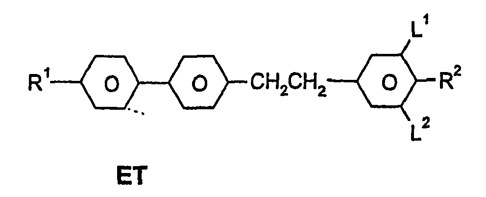


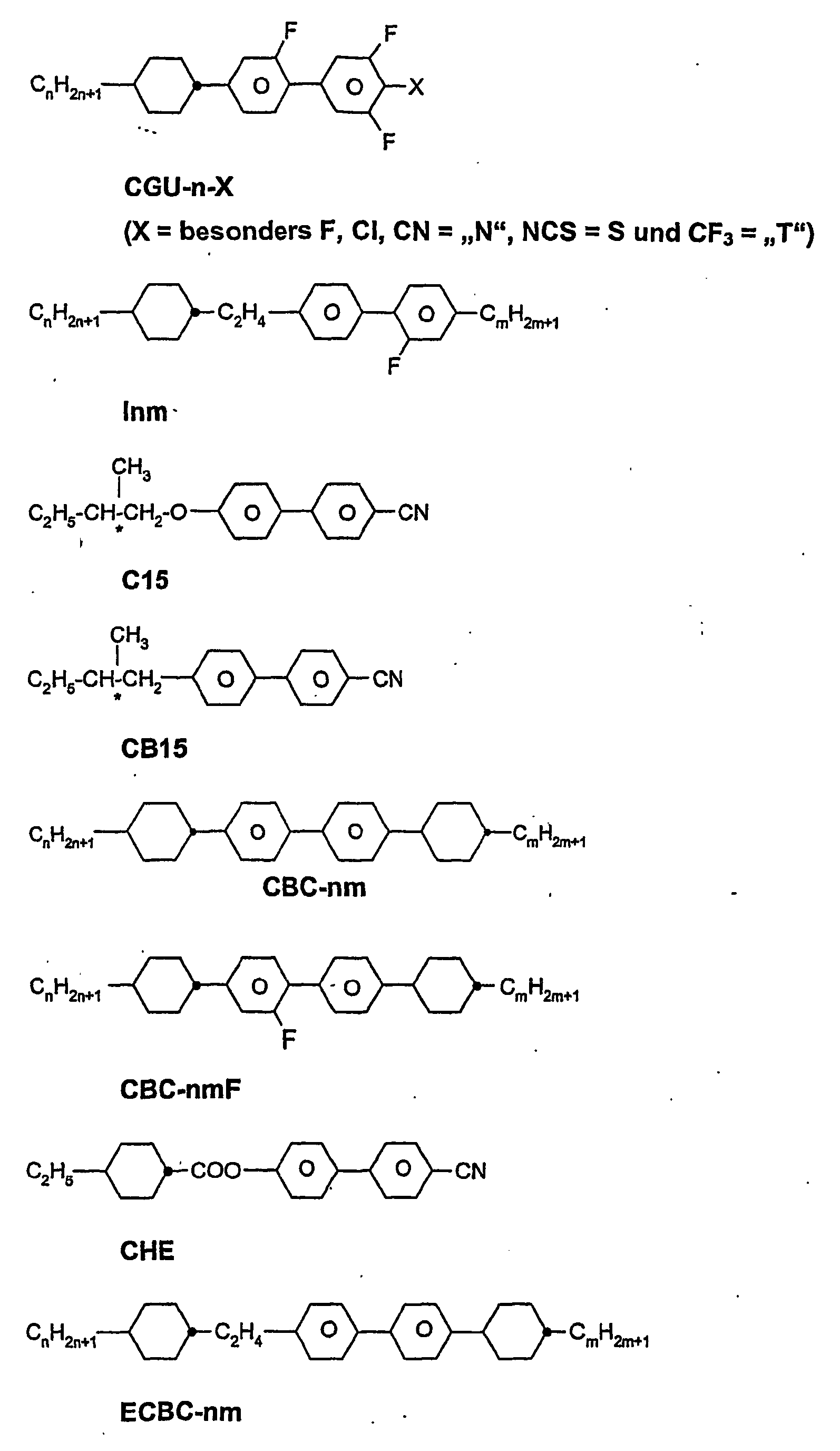


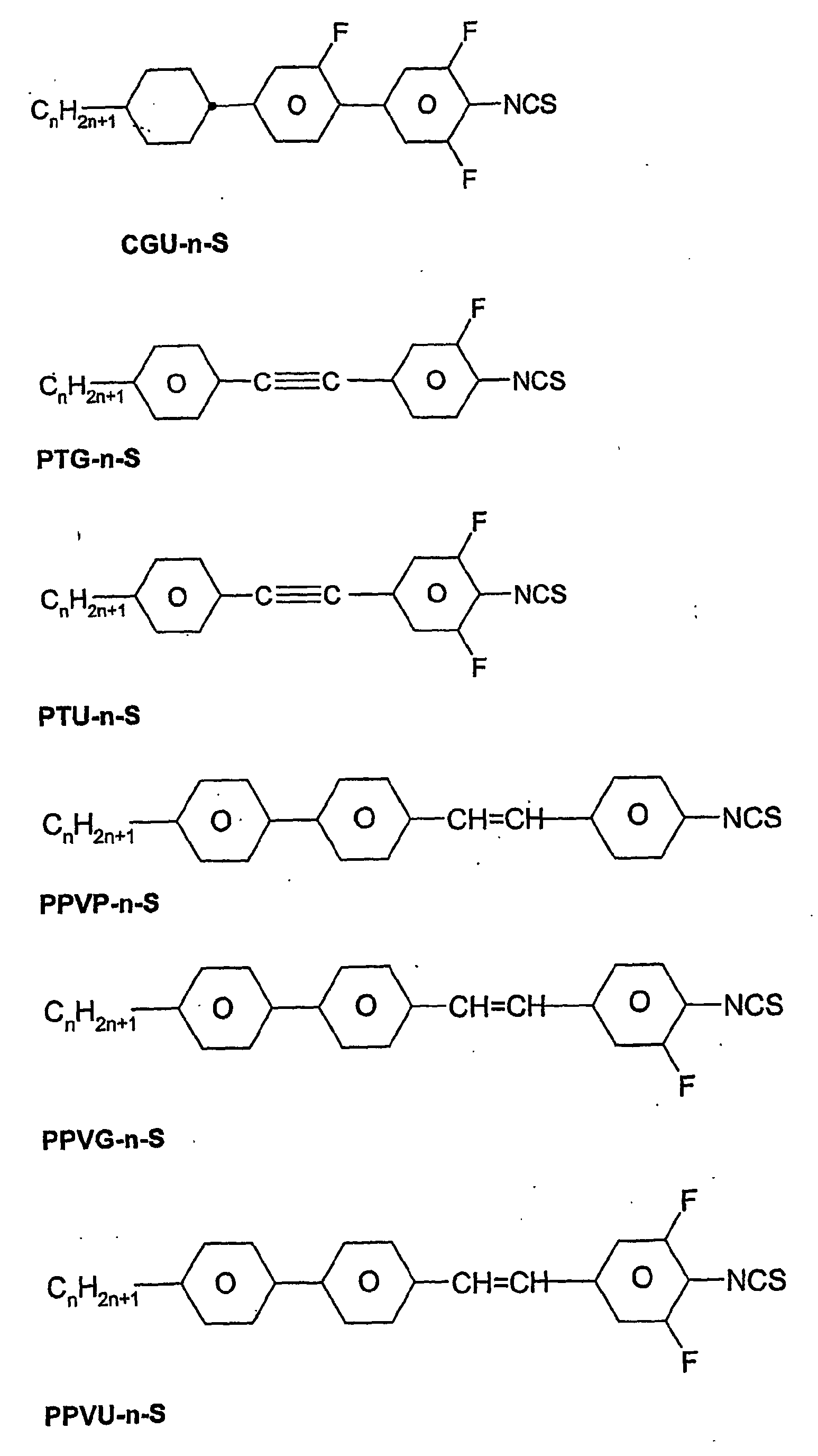
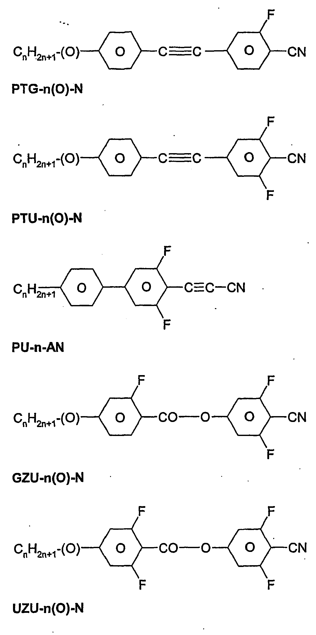


Die mesogenen Medien gemäß der vorliegenden Anmeldung enthalten bevorzugt
- vier oder mehr, bevorzugt sechs oder mehr, Verbindungen ausgewählt aus der Gruppe der Verbindungen der Tabellen A und B und/oder
- fünf oder mehr Verbindungen ausgewählt aus der Gruppe der Verbindungen der Tabelle B und/oder
- zwei oder mehr Verbindungen ausgewählt aus der Gruppe der Verbindungen der Tabelle A.
- four or more, preferably six or more, compounds selected from the group of the compounds of Tables A and B and / or
- five or more compounds selected from the group of compounds of Table B and / or
- two or more compounds selected from the group of compounds of Table A.
Die im Folgenden beschriebenen Beispiele illustrieren die vorliegende Erfindung ohne sie in irgend einer Art zu beschränken. Ferner zeigen sie dem Fachmann welche Eigenschaften und insbesondere welche Eigenschaftskombinationen mit der vorliegenden Erfindung erreicht werden können.The examples described below illustrate the present invention without limiting it in any way. Furthermore, they show those skilled in the art which properties and in particular which combination of properties can be achieved with the present invention.
Die Flüssigkristallmischung mit der folgenden Zusammensetzung wurde hergestellt und untersucht.
Diese Flüssigkristallmischung wurde in eine Testzelle gefüllt und bei einer Temperatur von 23,1°C, sowie bei 24,9°C (2° oberhalb des Klärpunkts) bezüglich ihrer elektrooptischen Eigenschaften untersucht.This liquid-crystal mixture was filled into a test cell and examined for its electro-optical properties at a temperature of 23.1 ° C, as well as at 24.9 ° C (2 ° above the clearing point).
Die verwendete Testzelle wies interdigitale Elektroden auf nur einem der beiden Substrate auf. Eine elektrooptische Testzelle mit einem Lichtschaltelement enthaltend die Flüssigkristallmischung wurde hergestellt. Die Substrate bestanden aus Glas. Es wurden Substrate ohne Orientierungsschicht und ohne Passivierungsschicht verwendet. Die Elektrodenstruktur bestand aus ineinander verzahnten kammförmigen Elektroden. Der Abstand der Elektroden betrug 15 µm und die Breite der Elektroden voneinander betrug 10 µm. Die Schichtdicke der Elektroden betrug ca. 100 nm. Die Elektroden befanden sich alle in einer gemeinsamen Ebene. Die Schichtdicke des Steuermediums betrug ca. 10 µm.The test cell used had interdigital electrodes on only one of the two substrates. An electro-optical test cell with a light switching element containing the liquid-crystal mixture was prepared. The substrates were made of glass. Substrates without orientation layer and without passivation layer were used. The electrode structure consisted of intermeshed comb-shaped electrodes. The distance of the electrodes was 15 μm and the width of the electrodes from each other was 10 μm. The layer thickness of the electrodes was about 100 nm. The electrodes were all in a common plane. The layer thickness of the control medium was about 10 microns.
Es wurde ein erster Polarisator vor und als Analysator ein zweiter Polarisator hinter der Zelle benutzt. Die Absorptionsachsen der beiden Polarisatoren bildeten einen Winkel von 90° zueinander. Der Winkel zwischen der Achse der maximalen Absorption der Polarisatoren und der Komponente des elektrischen Felds in der Ebene der Anzeige betrug jeweils 45°. Die Spannungs-Transmissions-Kennlinie wurde mit einem elektrooptischen Meßplatz DMS 703 der Firma Autronic-Melchers, Karlsruhe, Deutschland bestimmt. Bei senkrechter Beobachtung wurde eine Kurve erhalten wie sie für eine Zelle mit elektrisch kontrollierter Doppelbrechung (z. B. ECB) typisch ist.A first polarizer was used and a second polarizer behind the cell was used as the analyzer. The absorption axes of the two polarizers formed an angle of 90 ° to each other. The angle between the axis of maximum absorption of the polarizers and the component of the electric field in the plane of the display was each 45 °. The voltage-transmission characteristic curve was determined using an electro-optical measuring system DMS 703 from the company Autronic-Melchers, Karlsruhe, Germany. When observed perpendicularly, a curve was obtained which is typical for a cell with electrically controlled birefringence (eg ECB).
Bei 23,1°C liegt der Wert der Schwellenspannung (V10) bei 36,5 V, der Wert der Mittgrauspannung (V50) bei 28 V und der Wert der Sättigungsspannung (V90) bei 31,5 V. Das Maximum des relativen Kontrasts liegt bei 34 V. Bei 24,9°C beträgt V70 der 113 V. Diese Ergebnisse sind in Tabelle 1 zusammengestellt.
Wie man aus dieser Tabelle ersehen kann, sind die charakteristischen Spannungen der Flüssigkristallschaltelemente der Beispiele 1, 2, 5 und 8 signifikant niedriger als die der Vergleichsbeispiele 1 und 2. Die Erniedrigung liegt im Vergleich von Beispiel 1 zu Vergleichsbeispiel 1 bereits bei ca. 10 % und im Vergleich zu Vergleichsbeispiel 2 bei ca. 25 %.As can be seen from this table, the characteristic voltages of the liquid-crystal switching elements of Examples 1, 2, 5 and 8 are significantly lower than those of Comparative Examples 1 and 2. The reduction is already approximately 10% in the comparison of Example 1 to Comparative Example 1 and compared to Comparative Example 2 at about 25%.
Die Flüssigkristallmischung mit der folgenden Zusammensetzung wurde hergestellt und untersucht. Die Zusammensetzung und die Eigenschaften der Mischung sind in der folgenden Tabelle zusammengefaßt.
Wie bei Vergleichsbeispiel 1 wird eine elektro-optische Anzeige realisiert und deren Kennlinie vermessen. Bei einer Temperatur von 24,0°C beträgt der Wert der Schwellenspannung (V10) 22 V, der Wert der Mittgrauspannung (V50) 35,5 V und der Wert der Sättigungsspannung (V90) 44,5 V.As in Comparative Example 1, an electro-optical display is realized and measured their characteristic. At a temperature of 24.0 ° C, the value of the threshold voltage (V 10 ) is 22V, the value of the mid gray voltage (V 50 ) is 35.5V and the value of the saturation voltage (V 90 ) is 44.5V.
Bei einer Temperatur von 2 Grad oberhalb des Klärpunkts beträgt V70 134 V.At a temperature of 2 degrees above the clearing point, V 70 is 134 V.
Diese Ergebnisse sind zum Vergleich mit denen des Vergleichsbeispiels 1 Tabelle 1 enthalten.These results are included for comparison with those of Comparative Example 1 Table 1.
Die Flüssigkristallmischung mit der folgenden Zusammensetzung wurde hergestellt und untersucht.
Die Mischung wird in eine Testzelle gefüllt und wie im Vergleichsbeispiel 1 beschrieben untersucht. Insbesondere werden ihre elektrooptischen Eigenschaften bei einer Temperatur von 34,4°C bestimmt.The mixture is filled into a test cell and analyzed as described in Comparative Example 1. In particular, their electro-optical properties are determined at a temperature of 34.4 ° C.
Die so erhaltene Zelle erreichte bei einer Spannung von 103 V 70 % relativen Kontrast.The cell thus obtained reached 70% relative contrast at a voltage of 103V.
Diese Ergebnisse sind zum Vergleich mit denen der Vergleichsbeispiele 1 und 2 in Tabelle 1 enthalten.These results are included in Table 1 for comparison with those of Comparative Examples 1 and 2.
Die Flüssigkristallmischung mit der folgenden Zusammensetzung wurde hergestellt und untersucht.
Die Mischung wird in eine Testzelle gefüllt und wie im Vergleichsbeispiel 1 beschrieben untersucht. Insbesondere werden ihre elektrooptischen Eigenschaften bei einer Temperatur von 37,6 C bestimmt.The mixture is filled into a test cell and analyzed as described in Comparative Example 1. In particular, their electro-optical properties are determined at a temperature of 37.6C.
Die so erhaltene Zelle erreichte bei einer Spannung von 102 V 70 % relativen Kontrast. Diese Ergebnisse sind, zum Vergleich mit denen der Vergleichsbeispiele 1 und 2, ebenfalls in Tabelle 1 enthalten.The cell thus obtained reached 70% relative contrast at a voltage of 102V. These results are also included in Table 1 for comparison with those of Comparative Examples 1 and 2.
Die Flüssigkristallmischungen mit den folgenden Zusammensetzung werden hergestellt und untersucht.The liquid crystal mixtures having the following composition are prepared and tested.
Wie bei Beispiel 1 wurde die Mischung bei einer Temperatur von 2 oberhalb des Klärpunkts in einer Testzelle bezüglich ihrer elektrooptischen Eigenschaften untersucht, insbesondre wurde V70 zu 71 V bestimmt.As in Example 1, the mixture was examined for its electro-optical properties at a temperature of 2 above the clearing point in a test cell, in particular V 70 was determined to be 71V.
Außerdem wurde die Mischung bei einer Temperatur von 24,0°C in einer Testzelle bezüglich ihrer elektrooptischen Eigenschaften untersucht. Der Wert der Schwellenspannung (V10) lag bei 40,5 V, der Wert der Mittgrauspannung (V50) bei 56 V und der Wert der Sättigungsspannung (V90) bei 65 V. Der maximale Kontrast wurde bei 73 V erreicht. Bei Spannungen von 80 V bzw. 90 V sank der relative Kontrast wieder auf 90 % bzw. 50 % ab.In addition, the mixture was tested for its electro-optical properties at a temperature of 24.0 ° C in a test cell. The value of the threshold voltage (V 10 ) was 40.5 V, the value of the mid-gray voltage (V 50 ) was 56 V and the value of the saturation voltage (V 90 ) was 65 V. The maximum contrast was reached at 73 V. At voltages of 80 V or 90 V, the relative contrast dropped again to 90% and 50%, respectively.
Diese Ergebnisse sind, zum Vergleich mit denen der Vergleichsbeispiele 1 und 2 und der Beispiele 1 und 2, ebenfalls in Tabelle 1 enthalten.These results are also included in Table 1 for comparison with those of Comparative Examples 1 and 2 and Examples 1 and 2.
Diese Ergebnisse sind, zum Vergleich mit denen der Vergleichsbeispiele 1 bis 3 und der Beispiele 1 und 2, ebenfalls in Tabelle 1 enthalten.These results are also included in Table 1 for comparison with those of Comparative Examples 1 to 3 and Examples 1 and 2.
Das Steuermedium dieses Beispiels weist einen Übergang von der nematischen (hier stark verdrillten cholesterischen) Phase in die Blaue Phase auf. Es weist eine niedrige charakteristische Spannung V90 auf und ist durch eine besonders günstige, niedrige Temperaturabhängigkeit der charakteristischen Spannungen, auch im Vergleich mit den Beispielen 1 bis 8 der vorliegenden Anmeldung, gekennzeichnet.The control medium of this example has a transition from the nematic (here highly-twisted cholesteric) phase to the blue Phase up. It has a low characteristic voltage V 90 and is characterized by a particularly favorable, low temperature dependence of the characteristic voltages, also in comparison with Examples 1 to 8 of the present application.
Das Steuermedium dieses Beispiels weist, wie das des Beispiels 9, einen Übergang von der stark verdrillten cholesterischen Phase in die Blaue Phase auf. Es ist durch eine ganz besonders günstige, niedrige Temperaturabhängigkeit der charakteristischen Spannungen gekennzeichnet.The control medium of this example, like that of Example 9, has a transition from the highly-twisted cholesteric phase to the blue phase. It is characterized by a very favorable, low temperature dependence of the characteristic voltages.
Abbildung 1: Die Abbildung zeigt schematisch im Querschnitt den Aufbau eines Schaltelements oder eines Teils eines Schaltelements gemäß der vorliegenden Anmeldung. Zwischen den inneren Oberflächen der Substrate (1) und (1') befindet sich das Steuermedium (2). Auf der inneren Oberfläche des einen Substrats (1) befinden sich die beiden Elektroden (3) und (4) der Elektrodenstruktur, die mit voneinander verschiedenen Potentialen beaufschlagt werden können. Vop bezeichnet die Spannungs-, Ladungs- bzw. Stromquelle. Die von Vop ausgehenden Linien symbolisieren die elektrischen Zuleitungen zu den Elektroden. Figure 1 : The figure shows schematically in cross section the structure of a switching element or a part of a switching element according to the present application. Between the inner surfaces of the substrates (1) and (1 ') is the control medium (2). On the inner surface of the one substrate (1) are the two electrodes (3) and (4) of the electrode structure, which can be acted upon by mutually different potentials. Vop refers to the voltage, charge or current source. The lines emanating from Vop symbolize the electrical supply lines to the electrodes.
- 1 :1 :
- Oberfläche des ersten Substrats,Surface of the first substrate,
- 1' :1' :
- Oberfläche des 2. Substrats,Surface of the 2nd substrate,
- 2 :2:
- Steuerschicht,Control layer,
- 3 :3:
- Leitfähige Schicht der Elektrodenstruktur, die mit dem 1. Potential beaufschlagt werden kann,Conductive layer of the electrode structure which can be charged with the first potential
- 4 :4:
- Leitfähige Schicht der Elektrodenstruktur, die mit dem 2. Potential beaufschlagt werden kann,Conductive layer of the electrode structure, which can be charged with the second potential
- Vop :Vop:
- Spannungs-, Ladungs- bzw. StromquelleVoltage, charge or current source
Claims (29)
- Electro-optical light modulation element comprising- a substrate or a plurality of substrates,- an electrode arrangement,- at least one element or a plurality of elements for polarisation of the light and- a modulation medium,characterised in that- the light modulation element is operated at a temperature at which the modulation medium is in an optically isotropic phase in the unaddressed state and in that- the electrode arrangement can generate an electric field having a significant component parallel to the surface of the mesogenic modulation medium and in that- the mesogenic modulation medium satisfies at least one of the following conditions (a) and (f) and, in the case where it only satisfies condition (a) of these two conditions (a) and (f), it additionally satisfies at least one of the following conditions (b) and (c) and, in the case where it only satisfies condition (c) of conditions (b) and (c), it satisfies at least one of the two further following conditions (d) and (e) and, in the case where it satisfies condition (f), it optionally additionally satisfies condition (g),- (a) the modulation medium has, with increasing temperature, a transition from the nematic phase or from the cholesteric phase into the isotropic phase (T(N,I) or T(N*,I)), and the dielectric susceptibility of the modulation medium at a temperature of 4 degrees above the clearing point is 25 or more,- (b) the enthalpy of clearing of the modulation medium is 0.78 J/g or less or- (c) the enthalpy of clearing of the modulation medium is 1.50 J/g or less and- (d) the dielectric susceptibility of the modulation medium at a temperature of 4 degrees above the clearing point is 27 or more, with the proviso that light modulation elements containing modulation media which comprise 8%, 10% or 12% of compound UVZG-3-N are excluded, or- (e) the dielectric susceptibility of the modulation medium at a temperature of 4 degrees above the clearing point is 35.5 or more, with the proviso that light modulation elements containing modulation media having one of the two following compositions 1 and 2
Composition 1 Composition 2 Compound Conc. Compound Conc. # Abbreviation / % # Abbreviation / % 1 UZU-3A-N 12.0 1 UM-3-N 10.0 2 UZU-5A-N 12.0 2 PYP-3N.F.F 15.0 3 GZU-3A-N 12.0 3 UZU-3A-N 12.0 4 GZU-4A-N 11.0 4 GZU-3A-N 12.0 5 GZU-4O-N 10.0 5 GZU-4-N 1.0 6 UVZG-3-N 10.0 6 GZU-4O-N 10.0 7 CUZU-2-N 10.0 7 UVZG-3-N 10.0 8 CUZU-3-N 10.0 8 CUZU-2-N 10.0 9 CUZU-4-N 10.0 9 CUZU-3-N 10.0 10 HP-5N.F 3.0 10 HP-3N.F 10.0 - (f) the modulation medium has, with increasing temperature, a transition from the cholesteric phase (Ch, here referred to as the chiral nematic phase N*) into a blue phase (BP) at a temperature T(N*,BP) and- (g) the dielectric susceptibility of the modulation medium at a temperature of 4 degrees above this transition temperature (T(N*,BP)) is 25 or more. - Light modulation element according to Claim 1, characterised in that- the enthalpy of clearing of the mesogenic modulation medium is 1.10 J/g or less.
- Light modulation element according to Claim 2, characterised in that- the enthalpy of clearing of the mesogenic modulation medium is 0.70 J/g or less.
- Light modulation element according to at least one of Claims 1 to 3,
characterised in that- the dielectric susceptibility of the modulation medium at a temperature of 4 degrees above the clearing point or transition temperature (T(N*,BP) is 40 or more. - Light modulation element according to Claim 4, characterised in that- the dielectric susceptibility of the modulation medium at a temperature of 4 degrees above the clearing point or transition temperature (T(N*,BP) is 55 or more.
- Light modulation element according to at least one of Claims 1 to 5,
characterised in that- the optical anisotropy at a temperature of 4 degrees below the clearing point or transition temperature (T(N*,BP) is 0.080 or more. - Light modulation element according to at least one of Claims 1 to 6, characterised in that the mesogenic modulation medium comprises one or more compounds of the formula I
 R1 denotes alkyl having 1 to 7 C atoms or oxaalkyl having 2 to 7 C atoms,

 Z11 and Z12 each, independently of one another, denote a single bond, -CO-O-, trans -CH=CH-, -CH=CF-, -CF=CH-, -CF=CF-, -CH=CH-CO-O-, -CF=CF-CO-O-, -CF=CH-CO-O-, -CH=CF-CO-O-, -CF2-O-, -O-CF2- or -C≡C- or a combination of two or more of these groups,X1 denotes F, Cl, NO2, -OCF3, -CF3, -OCF2H, Cl, CN, -C≡C-CN or NCS,Y11, Y12, Y13 and Y14 each, independently of one another, denote H or F andn1 denotes 0 or 1.
 - Light modulation element according to at least one of Claims 1 to 7, characterised in that the mesogenic modulation medium comprises one or more compounds of the formula II
 R2 denotes alkyl or alkoxy having 1 to 7 C atoms, alkenyl, alkenyloxy or oxaalkyl having 2 to 7 C atoms,

 Z21 and Z22 each, independently of one another, denote a single bond, -CO-O-, trans -CH=CH-, -CH=CF-, -CF=CH-, -CF=CF-, -CH=CF-CO-O-, -CF2-O-, -O-CF2- or -C≡C- or a combination of two or more of these groups,X2 denotes F, Cl, NO2 -OCF3, -CF3, -OCF2H, Cl, CN, -C≡C-CN or NCS,Y2 denotes H or F andn2 denotes 0 or 1.
 - Light modulation element according to at least one of Claims 1 to 8, characterised in that, besides the compounds of the formulae I and/or II, the medium comprises one or more further mesogenic compounds.
- Light modulation element according to at least one of Claims 1 to 9, characterised in that the mesogenic modulation medium comprises- 5% to 80% of one or more compounds of the formula I and/or- 5% to 95% of one or more compounds of the formula II and/or- 0% to 30% of one or more further mesogenic compounds.
- Electro-optical display containing one or more light modulation elements according to at least one of Claims 1 to 10.
- Electro-optical display according to Claim 11, characterised in that the display is addressed by means of an active matrix.
- Electro-optical display system containing one or more electro-optical displays according to at least one of Claims 11 and 12.
- Electro-optical display system according to Claim 13, characterised in that it can be used as television screen, as computer monitor or as both.
- Use of a light modulation element according to at least one of Claims 1 to 10 for the display of information.
- Use of an electro-optical display according to at least one of Claims 11 and 12 in an electro-optical display system.
- Use of an electro-optical display system according to at least one of Claims 13 and 14 for the display of video signals or digital signals.
- Medium, characterised in that it satisfies the following condition (a) and at least one of the two further following conditions (b) and (c)- (a) the medium has, with increasing temperature, a transition from the nematic phase or from the cholesteric phase into the isotropic phase (T(N,I) or T(N*,I)) and the enthalpy of clearing of the medium is 1.50 J/g or less, and- (b) the dielectric susceptibility of the medium at a temperature of 4 degrees above the clearing point is 27 or more, with the proviso that media which comprise 8%, 10% or 12% of compound UVZG-3-N are excluded or- (c) the dielectric susceptibility of the medium at a temperature of 4 degrees above the clearing point is 35.5 or more, with the proviso that media having one of the two following compositions 1 and 2
Composition 1 Composition 2 Compound Conc. Compound Conc. # Abbreviation / % # Abbreviation / % 1 UZU-3A-N 12.0 1 UM-3-N 10.0 2 UZU-5A-N 12.0 2 PYP-3N.F.F 15.0 3 GZU-3A-N 12.0 3 UZU-3A-N 12.0 4 GZU-4A-N 11.0 4 GZU-3A-N 12.0 5 GZU-40-N 10.0 5 GZU-4-N 1.0 6 UVZG-3-N 10.0 6 GZU-4O-N 10.0 7 CUZU-2-N 10.0 7 UVZG-3-N 10.0 8 CUZU-3-N 10.0 8 CUZU-2-N 10.0 9 CUZU-4-N 10.0 9 CUZU-3-N 10.0 10 HP-5N.F 3.0 10 HP-3N.F 10.0
or in that the medium satisfies condition (d)- (d) the modulation medium has, with increasing temperature, a transition from the cholesteric phase into a blue phase (BP) at a temperature T(N*,BP) and in that optionally the dielectric susceptibility of the modulation medium at a temperature of 4 degrees above this transition temperature is 25 or more. - Medium according to Claim 18, characterised in that it has an enthalpy of clearing of 1.00 J/g or less.
- Medium according to Claim 19, characterised in that it has an enthalpy of clearing of 0.80 J/g or less.
- Medium according to at least one of Claims 18 to 20, characterised in that the dielectric susceptibility of the medium at a temperature of 4 degrees above the clearing point or conversion temperature is 40 or more.
- Medium according to Claim 21, characterised in that the dielectric susceptibility of the medium at a temperature of 4 degrees above the clearing point or conversion temperature is 55 or more.
- Medium according to at least one of Claims 18 to 22, characterised in that it has a clearing point or conversion temperature in the range from -30°C to 80°C.
- Medium according to Claim 23, characterised in that it has a clearing point or conversion temperature in the range from 0°C to 45°C.
- Medium according to at least one of Claims 18 to 24, characterised in that the optical anisotropy of the medium at a temperature of 4 degrees below the clearing point or conversion temperature is 0.080 or more.
- Medium according to at least one of Claims 18 to 25, characterised in that it comprises one or more compounds of the formula I as indicated in Claim 7.
- Medium according to at least one of Claims 18 to 26, characterised in that it comprises one or more compounds of the formula II as indicated in Claim 7.
- Medium according to at least one of Claims 18 to 27, characterised in that, besides the compounds of the formulae I and/or II, it comprises one or more further mesogenic compounds.
- Medium according to at least one of Claims 18 to 28, characterised in that the medium comprises- 5% to 80% of one or more compounds of the formula I and/or- 5% to 95% of one or more compounds of the formula II and/or- 0% to 30% of one or more further mesogenic compounds.
Applications Claiming Priority (3)
| Application Number | Priority Date | Filing Date | Title |
|---|---|---|---|
| DE10253325A DE10253325A1 (en) | 2002-11-14 | 2002-11-14 | Control medium for liquid crystal displays is characterized by having a clear enthalpy of no greater than 1.50 J/g and by having a dielectric susceptibility of at least 27 at 4 degrees above the clear point |
| DE10253325 | 2002-11-14 | ||
| PCT/EP2003/012327 WO2004044093A1 (en) | 2002-11-14 | 2003-11-05 | Electrooptic light control element, electrooptic display and control medium |
Publications (2)
| Publication Number | Publication Date |
|---|---|
| EP1560895A1 EP1560895A1 (en) | 2005-08-10 |
| EP1560895B1 true EP1560895B1 (en) | 2006-07-05 |
Family
ID=32185720
Family Applications (1)
| Application Number | Title | Priority Date | Filing Date |
|---|---|---|---|
| EP03779850A Expired - Lifetime EP1560895B1 (en) | 2002-11-14 | 2003-11-05 | Electrooptic light control element, electrooptic display and control medium |
Country Status (10)
| Country | Link |
|---|---|
| US (1) | US20060006363A1 (en) |
| EP (1) | EP1560895B1 (en) |
| JP (1) | JP2006506477A (en) |
| KR (1) | KR101123495B1 (en) |
| CN (1) | CN100396757C (en) |
| AT (1) | ATE332348T1 (en) |
| AU (1) | AU2003287998A1 (en) |
| DE (3) | DE10253325A1 (en) |
| TW (1) | TW200417773A (en) |
| WO (1) | WO2004044093A1 (en) |
Cited By (1)
| Publication number | Priority date | Publication date | Assignee | Title |
|---|---|---|---|---|
| CN102899050A (en) * | 2012-10-13 | 2013-01-30 | 江苏和成显示科技股份有限公司 | Liquid crystal composition and displayer having same |
Families Citing this family (40)
| Publication number | Priority date | Publication date | Assignee | Title |
|---|---|---|---|---|
| US7701628B2 (en) * | 2001-05-16 | 2010-04-20 | Merck Patent Gmbh | Electro-optic light control element, display and medium |
| JP5841301B2 (en) * | 2002-11-15 | 2016-01-13 | メルク パテント ゲゼルシャフト ミット ベシュレンクテル ハフツングMerck Patent Gesellschaft mit beschraenkter Haftung | Electro-optic light modulation element, electro-optic display and modulation medium |
| EP1831190A2 (en) | 2004-10-07 | 2007-09-12 | Merck Patent GmbH | Chroman derivatives and use thereof in liquid crystal media |
| JP5871445B2 (en) * | 2006-03-13 | 2016-03-01 | 国立大学法人九州大学 | Liquid crystal composition and liquid crystal element |
| KR101489528B1 (en) | 2007-05-16 | 2015-02-03 | 메르크 파텐트 게엠베하 | Modulation elements for electromagnetic radiation, modulation device and modulation medium |
| US7727417B2 (en) * | 2007-08-24 | 2010-06-01 | Chisso Corporation | Optically isotropic liquid crystal medium and optical device |
| US7879413B2 (en) * | 2007-08-29 | 2011-02-01 | Chisso Corporation | Optically isotropic liquid crystal medium and optical device |
| JP5577566B2 (en) | 2007-08-31 | 2014-08-27 | Jnc株式会社 | Liquid crystal composition and liquid crystal element |
| US7722783B2 (en) | 2007-11-20 | 2010-05-25 | Chisso Corporation | Optically isotropic liquid crystal medium and optical device |
| JP5544695B2 (en) | 2007-11-20 | 2014-07-09 | Jnc株式会社 | Optically isotropic liquid crystal medium and optical element |
| TWI506123B (en) | 2008-02-01 | 2015-11-01 | Merck Patent Gmbh | Liquid-crystalline medium and liquid-crystal display |
| KR101479996B1 (en) | 2008-02-21 | 2015-01-08 | 삼성디스플레이 주식회사 | Method for manufacturing display device |
| KR101577685B1 (en) * | 2008-05-15 | 2015-12-15 | 제이엔씨 주식회사 | Optically isotropic liquid crystalline medium, and optical element |
| JP5477296B2 (en) | 2008-11-19 | 2014-04-23 | Jnc株式会社 | Optically isotropic liquid crystal medium and optical element |
| TWI616707B (en) | 2008-11-28 | 2018-03-01 | 半導體能源研究所股份有限公司 | Liquid crystal display device |
| KR20100064215A (en) * | 2008-12-04 | 2010-06-14 | 삼성전자주식회사 | Display device |
| JP5625461B2 (en) * | 2009-05-19 | 2014-11-19 | Jnc株式会社 | Chlorofluorobenzene compound, optically isotropic liquid crystal medium and optical element |
| WO2010134430A1 (en) | 2009-05-19 | 2010-11-25 | チッソ株式会社 | Chlorobenzene derivative, optically isotropic liquid crystal medium, and optical element |
| US8323805B2 (en) | 2009-06-04 | 2012-12-04 | Nitto Denko Corporation | Emissive aryl-heteroaryl acetylenes |
| US8420235B2 (en) | 2009-06-04 | 2013-04-16 | Nitto Denko Corporation | Emissive diaryl acetylenes |
| CN102597862B (en) | 2009-08-28 | 2015-08-19 | 国立大学法人九州大学 | The liquid crystal display substrate that liquid crystal display cells and this liquid crystal display cells use |
| CN103038701B (en) * | 2010-03-29 | 2017-01-18 | 雷文布里克有限责任公司 | Polymer-stabilized thermotropic liquid crystal device |
| JP5799956B2 (en) | 2010-09-27 | 2015-10-28 | Jnc株式会社 | Optically isotropic liquid crystal medium and optical element |
| JP6386378B2 (en) * | 2011-09-06 | 2018-09-05 | メルク パテント ゲゼルシャフト ミット ベシュレンクテル ハフツングMerck Patent Gesellschaft mit beschraenkter Haftung | Liquid crystal medium and liquid crystal display |
| EP2568032B1 (en) * | 2011-09-06 | 2014-11-26 | Merck Patent GmbH | Liquid crystal medium and liquid crystal display |
| JP6306887B2 (en) | 2011-11-01 | 2018-04-04 | Jnc株式会社 | Optically isotropic liquid crystal medium and optical element |
| KR102048968B1 (en) | 2011-11-30 | 2019-11-27 | 제이엔씨 주식회사 | Liquid crystal composition, mixture, polymer/liquid crystal composite material and optical element |
| US9175222B2 (en) | 2012-05-28 | 2015-11-03 | Jnc Corporation | Optically isotropic liquid crystal medium and optical device |
| CN104379700B (en) | 2012-06-19 | 2018-12-28 | 捷恩智株式会社 | Liquid-crystal composition and application thereof, optical element, macromolecule and liquid crystal composite material, mixture and compound |
| EP2933310B1 (en) | 2012-12-17 | 2018-06-20 | JNC Corporation | Octahydro binaphthyl-based chiral compound-containing liquid-crystal composition and optical element |
| JP6327248B2 (en) | 2013-05-27 | 2018-05-23 | Jnc株式会社 | Liquid crystal medium, optical element, and liquid crystal compound |
| US10308870B2 (en) | 2013-12-10 | 2019-06-04 | Jnc Corporation | Liquid crystal medium, optical device and liquid crystal compound |
| TWI648381B (en) | 2014-07-03 | 2019-01-21 | 日商捷恩智股份有限公司 | Use of liquid crystal composition, optical element, mixture, compound, polymer/liquid crystal composite material, liquid crystal composition, and polymer/liquid crystal composite material |
| CN104560059B (en) * | 2014-12-12 | 2016-09-07 | 北京八亿时空液晶科技股份有限公司 | A kind of liquid crystal material and application thereof |
| JP2016121288A (en) | 2014-12-25 | 2016-07-07 | Jnc株式会社 | Optically isotropic liquid crystal medium and optical element |
| CN108239538B (en) * | 2016-12-23 | 2022-02-08 | 江苏和成显示科技有限公司 | Liquid crystal composition with negative dielectric anisotropy and application thereof |
| CN109143641B (en) * | 2017-06-28 | 2022-11-04 | 成均馆大学校产学协力团 | Optical element |
| CN113604227A (en) * | 2021-08-06 | 2021-11-05 | 南昌虚拟现实研究院股份有限公司 | Liquid crystal medium, preparation method thereof and liquid crystal lens |
| CN113773226B (en) * | 2021-08-06 | 2023-12-08 | 南昌虚拟现实研究院股份有限公司 | Process for producing cyanopropyne derivative, liquid crystal medium and liquid crystal lens |
| CN115627175A (en) * | 2022-09-30 | 2023-01-20 | 南昌虚拟现实研究院股份有限公司 | Liquid crystal composition and liquid crystal optical element |
Family Cites Families (9)
| Publication number | Priority date | Publication date | Assignee | Title |
|---|---|---|---|---|
| DE3425584A1 (en) * | 1984-07-11 | 1986-01-16 | Merck Patent Gmbh, 6100 Darmstadt | OPTICAL SYSTEM WITH A LIQUID CRYSTAL CELL, METHOD FOR ITS OPERATION AND USE |
| DE19541181A1 (en) * | 1995-11-04 | 1997-05-15 | Merck Patent Gmbh | 3,4,5-trifluorophenyl 4-cyclohexylbenzoic acid ester |
| DE60022229T2 (en) * | 2000-02-07 | 2006-03-30 | Merck Patent Gmbh | BENZOIC ACID ESTERS AND LIQUID CRYSTAL MEDIUM |
| EP1261679A1 (en) * | 2000-02-28 | 2002-12-04 | MERCK PATENT GmbH | Supertwisted nematic liquid crystal displays, liquid crystal compositions and compounds |
| EP1142977B1 (en) * | 2000-03-07 | 2003-11-19 | MERCK PATENT GmbH | Supertwisted nematic liquid crystal displays |
| DE10116400A1 (en) * | 2000-04-28 | 2001-12-06 | Merck Patent Gmbh | Liquid crystal medium containing compounds with strongly positive dielectric anisotropy, useful in electro-optical display devices |
| DE10151492B4 (en) * | 2000-11-02 | 2017-05-24 | Merck Patent Gmbh | Difluoracrylsäurederivate |
| JP5367203B2 (en) * | 2000-11-29 | 2013-12-11 | メルク パテント ゲゼルシャフト ミット ベシュレンクテル ハフツング | Electro-optical liquid crystal display and liquid crystal medium |
| US7701628B2 (en) * | 2001-05-16 | 2010-04-20 | Merck Patent Gmbh | Electro-optic light control element, display and medium |
-
2002
- 2002-11-14 DE DE10253325A patent/DE10253325A1/en not_active Withdrawn
-
2003
- 2003-11-05 JP JP2004550933A patent/JP2006506477A/en active Pending
- 2003-11-05 AU AU2003287998A patent/AU2003287998A1/en not_active Abandoned
- 2003-11-05 US US10/534,977 patent/US20060006363A1/en not_active Abandoned
- 2003-11-05 WO PCT/EP2003/012327 patent/WO2004044093A1/en active IP Right Grant
- 2003-11-05 KR KR1020057008486A patent/KR101123495B1/en not_active IP Right Cessation
- 2003-11-05 EP EP03779850A patent/EP1560895B1/en not_active Expired - Lifetime
- 2003-11-05 AT AT03779850T patent/ATE332348T1/en not_active IP Right Cessation
- 2003-11-05 DE DE50304163T patent/DE50304163D1/en not_active Expired - Lifetime
- 2003-11-05 CN CNB2003801032245A patent/CN100396757C/en not_active Expired - Fee Related
- 2003-11-05 DE DE10393333T patent/DE10393333D2/en not_active Withdrawn - After Issue
- 2003-11-13 TW TW092131794A patent/TW200417773A/en unknown
Cited By (1)
| Publication number | Priority date | Publication date | Assignee | Title |
|---|---|---|---|---|
| CN102899050A (en) * | 2012-10-13 | 2013-01-30 | 江苏和成显示科技股份有限公司 | Liquid crystal composition and displayer having same |
Also Published As
| Publication number | Publication date |
|---|---|
| CN100396757C (en) | 2008-06-25 |
| DE50304163D1 (en) | 2006-08-17 |
| JP2006506477A (en) | 2006-02-23 |
| US20060006363A1 (en) | 2006-01-12 |
| ATE332348T1 (en) | 2006-07-15 |
| KR20050086567A (en) | 2005-08-30 |
| DE10253325A1 (en) | 2004-05-27 |
| KR101123495B1 (en) | 2012-05-30 |
| WO2004044093A1 (en) | 2004-05-27 |
| DE10393333D2 (en) | 2005-09-29 |
| AU2003287998A1 (en) | 2004-06-03 |
| EP1560895A1 (en) | 2005-08-10 |
| TW200417773A (en) | 2004-09-16 |
| CN1711336A (en) | 2005-12-21 |
Similar Documents
| Publication | Publication Date | Title |
|---|---|---|
| EP1560895B1 (en) | Electrooptic light control element, electrooptic display and control medium | |
| DE10392930B4 (en) | Electro-optical light control element with medium with optically isotropic phase and thus equipped electro-optical displays | |
| EP1561150B1 (en) | Electrooptical light modulating element, electrooptical display and modulating medium | |
| WO2002093244A2 (en) | Electro-optic light control element, display and medium | |
| DE102008039750B4 (en) | Electro-optical light control element, electro-optical display and electro-optical display system and uses thereof | |
| EP2649154B1 (en) | Liquid crystal medium and electrooptic display | |
| EP2265691B1 (en) | Liquid crystalline medium | |
| DE10253606A1 (en) | Electro-optical light control element used in an electro-optical display system comprises one or more substrate, an electrode arrangement, one or more elements for polarizing light, and a control medium | |
| US6638581B2 (en) | Liquid-crystal medium, and electro-optical display containing the medium | |
| DE19943650A1 (en) | Liquid crystal display for plasma address display contains substituted 4-(trans-1,4-cyclohexylene)-2,3-difluoro phenylene derivatives | |
| DE102006033886A1 (en) | FK blends with low frequency dependency for TFT displays | |
| DE112007000676B4 (en) | Liquid-crystalline medium and its use | |
| DE10313979A1 (en) | Electrooptical light modulating element for data display in electrooptical, video or digital system, e.g. active matrix display, television screen and computer monitor, uses mesogenic modulating medium with blue phase | |
| EP1558965B1 (en) | Electro-optical light control element and display having a control medium with an optically isotropic phase | |
| DE60216211T2 (en) | Liquid-crystalline medium and liquid-crystal display | |
| WO2005083038A1 (en) | Method for adjusting the dispersion of liquid crystal media, liquid crystal media, and electro-optical displays containing the same | |
| DE10152831B4 (en) | Liquid-crystalline medium and its use | |
| EP1201727B1 (en) | Liquid crystalline medium and electro-optic liquid crystal display | |
| DE19828149A1 (en) | Super-twist liquid crystal display with very short switching time | |
| DE10140419A1 (en) | Low birefringence liquid crystalline medium | |
| DE602004001166T2 (en) | Liquid-crystalline medium and liquid-crystal display | |
| DE10135680A1 (en) | Liquid crystal medium with positive dielectric anisotropy, especially for multibottle systems or electrooptical displays, combines high specific resistance with low threshold voltage and low birefringence | |
| DE10336783A1 (en) | Electrooptical light modulating element for data display in electrooptical, video or digital system, e.g. active matrix display, television screen and computer monitor, uses mesogenic modulating medium with blue phase | |
| DE10145567B4 (en) | Liquid crystalline medium | |
| EP0592635A1 (en) | Tn cell with improved grey-shade representation |
Legal Events
| Date | Code | Title | Description |
|---|---|---|---|
| PUAI | Public reference made under article 153(3) epc to a published international application that has entered the european phase |
Free format text: ORIGINAL CODE: 0009012 |
|
| 17P | Request for examination filed |
Effective date: 20050404 |
|
| AK | Designated contracting states |
Kind code of ref document: A1 Designated state(s): AT BE BG CH CY CZ DE DK EE ES FI FR GB GR HU IE IT LI LU MC NL PT RO SE SI SK TR |
|
| AX | Request for extension of the european patent |
Extension state: AL LT LV MK |
|
| DAX | Request for extension of the european patent (deleted) | ||
| GRAP | Despatch of communication of intention to grant a patent |
Free format text: ORIGINAL CODE: EPIDOSNIGR1 |
|
| GRAS | Grant fee paid |
Free format text: ORIGINAL CODE: EPIDOSNIGR3 |
|
| GRAA | (expected) grant |
Free format text: ORIGINAL CODE: 0009210 |
|
| AK | Designated contracting states |
Kind code of ref document: B1 Designated state(s): AT BE BG CH CY CZ DE DK EE ES FI FR GB GR HU IE IT LI LU MC NL PT RO SE SI SK TR |
|
| PG25 | Lapsed in a contracting state [announced via postgrant information from national office to epo] |
Ref country code: IT Free format text: LAPSE BECAUSE OF FAILURE TO SUBMIT A TRANSLATION OF THE DESCRIPTION OR TO PAY THE FEE WITHIN THE PRESCRIBED TIME-LIMIT;WARNING: LAPSES OF ITALIAN PATENTS WITH EFFECTIVE DATE BEFORE 2007 MAY HAVE OCCURRED AT ANY TIME BEFORE 2007. THE CORRECT EFFECTIVE DATE MAY BE DIFFERENT FROM THE ONE RECORDED. Effective date: 20060705 Ref country code: NL Free format text: LAPSE BECAUSE OF FAILURE TO SUBMIT A TRANSLATION OF THE DESCRIPTION OR TO PAY THE FEE WITHIN THE PRESCRIBED TIME-LIMIT Effective date: 20060705 Ref country code: CZ Free format text: LAPSE BECAUSE OF FAILURE TO SUBMIT A TRANSLATION OF THE DESCRIPTION OR TO PAY THE FEE WITHIN THE PRESCRIBED TIME-LIMIT Effective date: 20060705 Ref country code: RO Free format text: LAPSE BECAUSE OF FAILURE TO SUBMIT A TRANSLATION OF THE DESCRIPTION OR TO PAY THE FEE WITHIN THE PRESCRIBED TIME-LIMIT Effective date: 20060705 Ref country code: IE Free format text: LAPSE BECAUSE OF FAILURE TO SUBMIT A TRANSLATION OF THE DESCRIPTION OR TO PAY THE FEE WITHIN THE PRESCRIBED TIME-LIMIT Effective date: 20060705 Ref country code: SI Free format text: LAPSE BECAUSE OF FAILURE TO SUBMIT A TRANSLATION OF THE DESCRIPTION OR TO PAY THE FEE WITHIN THE PRESCRIBED TIME-LIMIT Effective date: 20060705 Ref country code: FI Free format text: LAPSE BECAUSE OF FAILURE TO SUBMIT A TRANSLATION OF THE DESCRIPTION OR TO PAY THE FEE WITHIN THE PRESCRIBED TIME-LIMIT Effective date: 20060705 Ref country code: SK Free format text: LAPSE BECAUSE OF FAILURE TO SUBMIT A TRANSLATION OF THE DESCRIPTION OR TO PAY THE FEE WITHIN THE PRESCRIBED TIME-LIMIT Effective date: 20060705 |
|
| REG | Reference to a national code |
Ref country code: GB Ref legal event code: FG4D Free format text: NOT ENGLISH |
|
| REG | Reference to a national code |
Ref country code: CH Ref legal event code: EP |
|
| REG | Reference to a national code |
Ref country code: IE Ref legal event code: FG4D Free format text: LANGUAGE OF EP DOCUMENT: GERMAN |
|
| REF | Corresponds to: |
Ref document number: 50304163 Country of ref document: DE Date of ref document: 20060817 Kind code of ref document: P |
|
| PG25 | Lapsed in a contracting state [announced via postgrant information from national office to epo] |
Ref country code: DK Free format text: LAPSE BECAUSE OF FAILURE TO SUBMIT A TRANSLATION OF THE DESCRIPTION OR TO PAY THE FEE WITHIN THE PRESCRIBED TIME-LIMIT Effective date: 20061005 Ref country code: BG Free format text: LAPSE BECAUSE OF FAILURE TO SUBMIT A TRANSLATION OF THE DESCRIPTION OR TO PAY THE FEE WITHIN THE PRESCRIBED TIME-LIMIT Effective date: 20061005 Ref country code: SE Free format text: LAPSE BECAUSE OF FAILURE TO SUBMIT A TRANSLATION OF THE DESCRIPTION OR TO PAY THE FEE WITHIN THE PRESCRIBED TIME-LIMIT Effective date: 20061005 |
|
| PG25 | Lapsed in a contracting state [announced via postgrant information from national office to epo] |
Ref country code: ES Free format text: LAPSE BECAUSE OF FAILURE TO SUBMIT A TRANSLATION OF THE DESCRIPTION OR TO PAY THE FEE WITHIN THE PRESCRIBED TIME-LIMIT Effective date: 20061016 |
|
| GBT | Gb: translation of ep patent filed (gb section 77(6)(a)/1977) |
Effective date: 20060924 |
|
| PG25 | Lapsed in a contracting state [announced via postgrant information from national office to epo] |
Ref country code: BE Free format text: LAPSE BECAUSE OF NON-PAYMENT OF DUE FEES Effective date: 20061130 Ref country code: MC Free format text: LAPSE BECAUSE OF NON-PAYMENT OF DUE FEES Effective date: 20061130 |
|
| NLV1 | Nl: lapsed or annulled due to failure to fulfill the requirements of art. 29p and 29m of the patents act | ||
| PG25 | Lapsed in a contracting state [announced via postgrant information from national office to epo] |
Ref country code: PT Free format text: LAPSE BECAUSE OF FAILURE TO SUBMIT A TRANSLATION OF THE DESCRIPTION OR TO PAY THE FEE WITHIN THE PRESCRIBED TIME-LIMIT Effective date: 20061205 |
|
| REG | Reference to a national code |
Ref country code: IE Ref legal event code: FD4D |
|
| EN | Fr: translation not filed | ||
| PLBE | No opposition filed within time limit |
Free format text: ORIGINAL CODE: 0009261 |
|
| STAA | Information on the status of an ep patent application or granted ep patent |
Free format text: STATUS: NO OPPOSITION FILED WITHIN TIME LIMIT |
|
| 26N | No opposition filed |
Effective date: 20070410 |
|
| BERE | Be: lapsed |
Owner name: MERCK PATENT G.M.B.H. Effective date: 20061130 |
|
| PG25 | Lapsed in a contracting state [announced via postgrant information from national office to epo] |
Ref country code: AT Free format text: LAPSE BECAUSE OF NON-PAYMENT OF DUE FEES Effective date: 20061105 |
|
| PG25 | Lapsed in a contracting state [announced via postgrant information from national office to epo] |
Ref country code: GR Free format text: LAPSE BECAUSE OF FAILURE TO SUBMIT A TRANSLATION OF THE DESCRIPTION OR TO PAY THE FEE WITHIN THE PRESCRIBED TIME-LIMIT Effective date: 20061006 Ref country code: FR Free format text: LAPSE BECAUSE OF FAILURE TO SUBMIT A TRANSLATION OF THE DESCRIPTION OR TO PAY THE FEE WITHIN THE PRESCRIBED TIME-LIMIT Effective date: 20070511 |
|
| PGFP | Annual fee paid to national office [announced via postgrant information from national office to epo] |
Ref country code: GB Payment date: 20071031 Year of fee payment: 5 |
|
| PG25 | Lapsed in a contracting state [announced via postgrant information from national office to epo] |
Ref country code: EE Free format text: LAPSE BECAUSE OF FAILURE TO SUBMIT A TRANSLATION OF THE DESCRIPTION OR TO PAY THE FEE WITHIN THE PRESCRIBED TIME-LIMIT Effective date: 20060705 |
|
| PG25 | Lapsed in a contracting state [announced via postgrant information from national office to epo] |
Ref country code: CH Free format text: LAPSE BECAUSE OF NON-PAYMENT OF DUE FEES Effective date: 20071130 Ref country code: HU Free format text: LAPSE BECAUSE OF FAILURE TO SUBMIT A TRANSLATION OF THE DESCRIPTION OR TO PAY THE FEE WITHIN THE PRESCRIBED TIME-LIMIT Effective date: 20070106 Ref country code: LI Free format text: LAPSE BECAUSE OF NON-PAYMENT OF DUE FEES Effective date: 20071130 Ref country code: LU Free format text: LAPSE BECAUSE OF NON-PAYMENT OF DUE FEES Effective date: 20061105 Ref country code: TR Free format text: LAPSE BECAUSE OF FAILURE TO SUBMIT A TRANSLATION OF THE DESCRIPTION OR TO PAY THE FEE WITHIN THE PRESCRIBED TIME-LIMIT Effective date: 20060705 |
|
| REG | Reference to a national code |
Ref country code: CH Ref legal event code: PL |
|
| PG25 | Lapsed in a contracting state [announced via postgrant information from national office to epo] |
Ref country code: FR Free format text: LAPSE BECAUSE OF FAILURE TO SUBMIT A TRANSLATION OF THE DESCRIPTION OR TO PAY THE FEE WITHIN THE PRESCRIBED TIME-LIMIT Effective date: 20060705 Ref country code: CY Free format text: LAPSE BECAUSE OF FAILURE TO SUBMIT A TRANSLATION OF THE DESCRIPTION OR TO PAY THE FEE WITHIN THE PRESCRIBED TIME-LIMIT Effective date: 20060705 |
|
| GBPC | Gb: european patent ceased through non-payment of renewal fee |
Effective date: 20081105 |
|
| PG25 | Lapsed in a contracting state [announced via postgrant information from national office to epo] |
Ref country code: GB Free format text: LAPSE BECAUSE OF NON-PAYMENT OF DUE FEES Effective date: 20081105 |
|
| PGFP | Annual fee paid to national office [announced via postgrant information from national office to epo] |
Ref country code: DE Payment date: 20121031 Year of fee payment: 10 |
|
| PG25 | Lapsed in a contracting state [announced via postgrant information from national office to epo] |
Ref country code: DE Free format text: LAPSE BECAUSE OF NON-PAYMENT OF DUE FEES Effective date: 20140603 |
|
| REG | Reference to a national code |
Ref country code: DE Ref legal event code: R119 Ref document number: 50304163 Country of ref document: DE Effective date: 20140603 |