EP1560424B1 - Electronic motion picture camera - Google Patents
Electronic motion picture camera Download PDFInfo
- Publication number
- EP1560424B1 EP1560424B1 EP04030976.7A EP04030976A EP1560424B1 EP 1560424 B1 EP1560424 B1 EP 1560424B1 EP 04030976 A EP04030976 A EP 04030976A EP 1560424 B1 EP1560424 B1 EP 1560424B1
- Authority
- EP
- European Patent Office
- Prior art keywords
- image
- camera
- viewfinder
- electronic display
- taking sensor
- Prior art date
- Legal status (The legal status is an assumption and is not a legal conclusion. Google has not performed a legal analysis and makes no representation as to the accuracy of the status listed.)
- Active
Links
- 230000033001 locomotion Effects 0.000 title claims description 42
- 230000003287 optical effect Effects 0.000 claims description 70
- 238000011156 evaluation Methods 0.000 claims description 29
- 238000000034 method Methods 0.000 claims description 10
- 238000012545 processing Methods 0.000 claims description 6
- 230000005693 optoelectronics Effects 0.000 claims description 5
- 239000003086 colorant Substances 0.000 claims description 4
- 239000011521 glass Substances 0.000 claims description 4
- 239000004973 liquid crystal related substance Substances 0.000 claims description 4
- 230000001105 regulatory effect Effects 0.000 claims 1
- 238000011144 upstream manufacturing Methods 0.000 claims 1
- 239000005337 ground glass Substances 0.000 description 21
- 238000001454 recorded image Methods 0.000 description 6
- 230000006870 function Effects 0.000 description 5
- 238000012805 post-processing Methods 0.000 description 4
- 230000008901 benefit Effects 0.000 description 3
- 239000010408 film Substances 0.000 description 3
- 230000012447 hatching Effects 0.000 description 3
- 238000011161 development Methods 0.000 description 2
- 230000018109 developmental process Effects 0.000 description 2
- 230000004907 flux Effects 0.000 description 2
- 238000012986 modification Methods 0.000 description 2
- 230000004048 modification Effects 0.000 description 2
- 238000002360 preparation method Methods 0.000 description 2
- 239000013589 supplement Substances 0.000 description 2
- 230000002123 temporal effect Effects 0.000 description 2
- 238000012360 testing method Methods 0.000 description 2
- 230000006978 adaptation Effects 0.000 description 1
- 230000003321 amplification Effects 0.000 description 1
- 230000005540 biological transmission Effects 0.000 description 1
- 230000008859 change Effects 0.000 description 1
- 230000001419 dependent effect Effects 0.000 description 1
- 238000005562 fading Methods 0.000 description 1
- 230000000977 initiatory effect Effects 0.000 description 1
- 239000000463 material Substances 0.000 description 1
- 238000005259 measurement Methods 0.000 description 1
- 238000003199 nucleic acid amplification method Methods 0.000 description 1
- 230000035699 permeability Effects 0.000 description 1
- 239000000523 sample Substances 0.000 description 1
- 230000011218 segmentation Effects 0.000 description 1
- 239000010409 thin film Substances 0.000 description 1
Images


Classifications
-
- H—ELECTRICITY
- H04—ELECTRIC COMMUNICATION TECHNIQUE
- H04N—PICTORIAL COMMUNICATION, e.g. TELEVISION
- H04N5/00—Details of television systems
- H04N5/222—Studio circuitry; Studio devices; Studio equipment
- H04N5/2224—Studio circuitry; Studio devices; Studio equipment related to virtual studio applications
-
- G—PHYSICS
- G03—PHOTOGRAPHY; CINEMATOGRAPHY; ANALOGOUS TECHNIQUES USING WAVES OTHER THAN OPTICAL WAVES; ELECTROGRAPHY; HOLOGRAPHY
- G03B—APPARATUS OR ARRANGEMENTS FOR TAKING PHOTOGRAPHS OR FOR PROJECTING OR VIEWING THEM; APPARATUS OR ARRANGEMENTS EMPLOYING ANALOGOUS TECHNIQUES USING WAVES OTHER THAN OPTICAL WAVES; ACCESSORIES THEREFOR
- G03B13/00—Viewfinders; Focusing aids for cameras; Means for focusing for cameras; Autofocus systems for cameras
- G03B13/02—Viewfinders
- G03B13/06—Viewfinders with lenses with or without reflectors
Definitions
- the invention relates to an electronic motion picture camera having a receiving optical system and a beam splitter which divides the receiving beam path into a recording beam path leading to an optoelectronic recording sensor and to a viewfinder beam path leading to an optical viewfinder.
- the recorded useful signal is usually displayed as a monitor image in an electronic viewfinder or on a screen attached to the camera.
- the thus reproduced picture image serves, for example, to control the sharpness.
- An electronic viewfinder has the disadvantage that the environment of the recorded image can not be observed. Thus, potentially disturbing objects outside the captured image detail can not be detected before they enter the image. Above all, viewfinders based on electronic displays are limited in the quality of reproduction.
- an electronic motion picture camera in which a rotating mirror aperture divides the reception beam path into a recording beam path and a viewfinder beam path, wherein a matted glass pane and a viewfinder optics are arranged in the viewfinder beam path.
- the EP-A-0152496 describes an electronic camera with a beam splitter in the receiving beam path and a semi-transparent mirror in the viewfinder beam path.
- a combination of a binary and the analog video signal can be displayed, which is observable by means of the semitransparent mirror in the viewfinder.
- the binary video signal indicates areas of overexposure or underexposure.
- the viewfinder has a high image quality and can be flexibly used for different Anêten in terms of the reproduction of the image and other image information. Furthermore, a corresponding method should be created.
- the receiving optics thus images the recording image along the recording beam path onto the recording sensor and also displays the recording image in the viewfinder, wherein the camera according to the invention has a hybrid finder system with two superimposed beam paths:
- an optical image mixer is integrated the display of the receiving image captured by the receiving optics and an additional image generated by an electronic display allows, wherein the image and the additional image can be displayed to the viewer in the viewfinder as a single, uniform motion picture.
- the high image quality of an optical viewfinder is combined with the possibility of incorporating additional image information in the viewfinder beam path by means of an electronic display or of initiating it optically in some other way.
- the additional image can thus support the cameraman in a variety of ways during the recording, wherein the image information contained therein can be flexibly selected as a function of the specific recording situation.
- the actual image and the additional image can be displayed either simultaneously, alternatively to each other, alternating in time or alternately with a temporal overlap in the optical viewfinder.
- the electronic display is designed for reproducing motion pictures which supplement the actual recording image presented in the viewfinder.
- the viewfinder is designed as an optical viewfinder, a high image quality is ensured, without the known technical limitations of an electronic monitor image.
- the optical viewfinder can be configured in such a way that the image section imaged by the receiving optics in the direction of the viewfinder is larger than the image section of the image actually taken by the image sensor, so that the cameraman can also observe the surroundings of the image section actually taken.
- Stored motion picture sequences are superimposed on the actual recording image during a new recording, namely as a reference for the camera work.
- the rotation of the mirror aperture inevitably leads to an intermittent fading of the light incident on the recording sensor.
- these blanking time intervals can be reduced compared to those time intervals in which the incident light is deflected in the direction of the viewfinder.
- the resulting flicker in the viewfinder can namely be compensated for by the image recorded by the sensor is introduced into the viewfinder beam path via the electronic display and the optical image mixer.
- the illustrated camera is designed as a digital electronic motion picture camera with a digitization device connected downstream of the recording sensor.
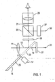
- Fig. 1 shows a first embodiment of an electronic motion picture camera.
- This has a receiving optics 11, which images the recorded motion picture along a received beam path 13.
- a serving as a beam splitter mirror aperture 15 which can be driven by a drive unit 17 to a rotational movement, the incident along the receiving beam path 13 light is alternately transmitted in the direction of a recording beam path 19 or deflected in the direction of a viewfinder beam path 21.
- the mirror panel 15 has a transmission area 23 and a mirrored Ausblend Scheme 25th
- a captured image of the receiving optical system 11 is thus alternately imaged along the recording beam path 19 on an optoelectronic recording sensor 27 and deflected along the viewfinder beam path 21 to be displayed in an optical viewfinder 29.
- the pickup sensor 27 is formed by, for example, a CCD or CMOS imager, and has a signal output 31 for outputting a reception signal.
- a ground glass 33 is arranged, on which the captured by the receiving optical system 11 image is displayed, provided that the Ausblend Scheme 25 of the mirror aperture 15 is located in the receiving beam path 13. This results in a realistic image on the screen 33, which the cameraman can look at by means of the viewfinder 29.
- an optical image mixer 35 is further arranged, on the one hand allows the viewing of the ground glass 33 through the viewfinder 29 and on the other hand brings a reproduced by an electronic display 37 additional image in the viewfinder 29 for illustration.
- the optical image mixer 35 the additional image of the electronic display 37 is thus superimposed on the ground-glass image, with the viewer viewing the two superimposed images in the viewfinder 29 as a single image with a corresponding adaptation of the two optical branches.
- the display 37 and the ground glass 33 are arranged in the same object plane or focal position of the viewfinder 29.
- the optical image mixer 35 is formed, for example, by a partially transmissive mirror.
- the electronic display 37 is formed by, for example, a liquid crystal monitor, a thin film transistor (TFT) monitor, or a cathode ray tube (CRT). It has a signal input 39, via which the additional image or corresponding image signals can be supplied.
- TFT thin film transistor
- CRT cathode ray tube
- an optical viewfinder 29 in conjunction with a ground glass 33 ensures a high quality of the viewfinder image.
- the cameraman in the viewfinder 29 by means of the display 37 and the image mixer 35, an additional image be displayed to thereby support the recording in a variety and flexible manner.
- motion pictures or still pictures can be displayed on the electronic display 37, which temporally supplement the recording picture intermittently imaged on the ground glass screen 33, so that a flickering of the imaged recording picture possibly caused by the rotation of the mirror screen 15 is avoided.
- the electronic display 37 and the optical image mixer 35 can also be used to display a motion picture sequence just recorded in the viewfinder 29 for control purposes.
- any other image information can be mirrored into the viewfinder beam path 21 by means of the display 37 and the image mixer 35.
- the capture sensor 27 can provide a receive signal during the recording preparations , which is used, for example, for testing and reference purposes.
- an image observation in the viewfinder 29 is possible by the received signal of the recording sensor 27 is supplied via the signal input 39 of the electronic display 37 and is brought from this via the optical image mixer 35 in the viewfinder 29 for display.
- the camera has an adjusting device, by means of which the reproduction of the additional image of the electronic display 37 can be adjusted relative to the recording image imaged on the ground glass 33.
- the reproduction of the additional image of the electronic display 37 can be adjusted relative to the recording image imaged on the ground glass 33.
- this adjustment for example, the size, position, orientation or other geometric properties of the Additional image adapted to achieve a geometry identical overlay with the image in the viewfinder 29.
- this adjustment is done in an electronic manner.
- the ground glass 33, the optical image mixer 35 and the viewfinder 29 are arranged in an L-shape, so that the image mixer 35 deflects the recorded image on the focusing screen 33 in the direction of the sensor 29, while the additional image of the electronic display 37, for example, rectilinear is reproduced by the image mixer 35 in the direction of the viewfinder 29.
- the receiving optics 11 in the viewfinder beam path 21 can generate a virtual image that can be viewed in the viewfinder 29 together with the additional image of the display 37.
- a beam splitter can in principle also be provided, which divides the incident luminous flux continuously.
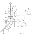
- Fig. 2 shows a development of the embodiment according to Fig. 1 ,
- a recording sensor 27 downstream of the signal processing device 41 is provided. This prepares the received signal of the recording sensor 27, for example by amplification and preferably by additional digitization.
- the processed signal is output on the one hand at the signal output 31 as a useful signal and transmitted to the other to the electronic display 37.
- the electronic display 37 can thus reproduce the actual received signal of the recording sensor 27 in real time as an additional image.
- the recording image recorded by the recording sensor 27 is superimposed or temporally supplemented with that recording image which is imaged on the ground glass 33 by the receiving optical system 11 via the rotating mirror diaphragm 15.
- the observable image in the viewfinder 29 appears particularly quiet, without annoying flicker.
- a control device 43 which synchronizes the drive unit 17 of the mirror shutter 15, the pick-up sensor 27 and the electronic display 37 in such a way that in the viewfinder 29 substantially alternately, i. exactly alternately or with a temporal overlap, which can be observed by the receiving optical system 11 via the mirror aperture 15 on the ground-glass screen 33 recorded image and reproduced by the electronic display 37 received signal of the recording sensor 27.
- the drive unit 17 of the mirror aperture 15 also drive such that during a recording sequence to be recorded, the receiving optical system 11 images the image only on the recording sensor 27.
- the mirror aperture 15 is temporarily brought to a standstill, so that the passband 23 is located in the receiving beam path 13. Since the recording image is thus no longer imaged on the ground glass 33, the control device 43 causes the display 37 to reproduce the current received signal of the recording sensor 27 as an additional image during the entire image sequence.
- the viewfinder 29 thus serves as a purely electronic viewfinder. This is particularly advantageous in low light conditions, since the entire received light can be directed completely onto the pick-up sensor 27.
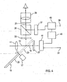
- Fig. 3 shows a development in which the image sensor 27 and a signal processing device 41, an image memory device 45 is connected downstream. This supplies at a signal output 31, the processed received signal of the recording sensor 27. Another signal output is connected to an input of the electronic display 37.
- motion picture data or still picture data recorded at an earlier time by the pickup sensor 27 and stored in the image memory means 45 can be reproduced on the electronic display 37 and thus observed in the optical finder 29.
- the image storage device 45 thereby allows the viewing of a previously recorded motion picture sequence in the viewfinder 29, without the need for an additional image monitor is required.
- a particular advantage of the embodiment according to Fig. 3 is that during a new shot the recorded image on the ground glass 33, a previously recorded by means of the recording sensor 27 motion picture sequence can be superimposed, for example, to provide the cameraman with a reference for the camera.
- the electronic display 37 or a data buffer connected thereto may have a signal input 39 to which an external memory device 47 can be connected in order to supply the electronic display 37 with motion picture data or still image data which is reproduced by means of the optical image mixer 35 in the viewfinder 29 as an additional image should be.
- an external memory device 47 By connecting an external memory device 47, it is possible, in particular, to reproduce on the electronic display 37 mathematically generated or processed picture elements which are to be inserted in the post-processing of the recording. By making these picture elements visible to the cameraman during the recording, they can work together take into account the real scene with the virtual picture elements. The camera operation is thereby greatly facilitated, and it is avoided that a recorded motion picture sequence subsequently proves to be unsuitable for the desired post-processing.
- the explained fade an additional motion picture sequence in the optical viewfinder 29 so for the so-called compositing, so for the recording of subjects against a blue background (blue screen) for the subsequent superimposition of several different subjects in the post.
- the recording of a real actor in front of a blue screen is later superimposed with an artificially or trick-technically produced representation of another character (eg an alien or the like)
- the cameraman can already record the cameraman during the recording of the real actor in front of the blue screen artificially generated representation by means of the electronic display 37 are faded into the optical viewfinder 29.
- the cameraman can thus simultaneously observe the real shot and the additionally displayed representation of the trickischen motif and affect the camera work accordingly, so that it is ensured that the final superimposition of the real and the artificial scene in post-processing is easily possible.
- Fig. 4 shows a modification of the embodiment according to Fig. 3 ,
- an evaluation and control device 49 is connected on the input side to a signal processing device 41 connected downstream of the recording sensor 27.
- the evaluation and control device 49 is connected to an image memory device 45, which is connected to the electronic display 37.
- the evaluation and control device 49 is configured to control the timing of reproduction of a motion picture sequence stored in the image memory device 45 on the electronic display 37 depending on the camera run. In a simple case, the motion picture sequence is reproduced as soon as the evaluation and control device 49 detects the beginning of the camera run or a recording by means of the recording sensor 27.
- the evaluation and control device 49 can also be configured such that it evaluates the current received signal of the recording sensor 27 with respect to an object movement within the recording image and controls the playback frequency in dependence thereon, with the motion picture data or still image data stored in the image memory device 45 on the electronic display 37 be reproduced.
- a previously recorded motion picture sequence serving as a reference for the camera guide may be stored, or the image data stored in the image memory device 45 may correspond to virtual picture elements to be inserted in post-processing of the photograph.
- the evaluation and control device 49 is able to control the playback of this stored image data (start and end point, running speed) in dependence on the camera run and / or the received signal of the recording sensor 27 to ensure synchronization of the stored events with the real recording.
- the image data to be input via the electronic display 37 may alternatively originate from an external storage device.
- the additional image over a signal input 39 is supplied to the camera, wherein the image memory device 45 can serve as a data buffer.
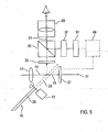
- Fig. 5 shows an embodiment in which the display 37 is connected on the input side to an image generator 51, which generates as an additional image to be displayed on the display 37, for example, image area markings, image format marks, other graphic information or alphanumeric information.
- image generator 51 which generates as an additional image to be displayed on the display 37, for example, image area markings, image format marks, other graphic information or alphanumeric information.
- the image generator 51 by means of the image generator 51, the display 37 and the image mixer 35, a frame can be superimposed on the picture image imaged on the ground glass 33, which marks the image detail of the assigned image format depending on the destination of the recording (cinema or television).
- the image information generated by the image generator 51 can also be, for example, an alphanumeric identification of the set aperture or of the set depth of focus range.
- the image generator 51 is connected on the input side to an evaluation and control device 49, which in turn is connected to the input sensor 27 or an associated signal processing device on the input side.
- the evaluation and control device 49 evaluates the received signal of the recording sensor 27 with respect to predetermined brightness or sharpness values and causes the image generator to generate corresponding brightness range markings or focus area markings, which are displayed on the electronic display 37.
- the evaluation and control device 49 can compare the received signal of the recording sensor 27 for the individual pixels of the recording image, for example, by means of a comparator with an upper brightness threshold value or with a lower brightness threshold value or with the two aforementioned brightness threshold values.
- the evaluation and control device 49 can calculate or specify at least one brightness range of the recording image within which the respective received signal exceeds the upper brightness threshold value or undershoots the lower brightness threshold value for the pixels of the recording image or at least for a majority of the pixels.
- the image generator 51 generates due to the thus defined brightness ranges corresponding brightness range markings, for example, the already mentioned hatching. These brightness range markings are thus generated on the display 37 and are thus visible in the optical viewfinder 29 as warnings superimposed on the recorded image.
- this function is important for the actual, final recording, as the cameraman thus has a control that actually no problematic brightness is recorded during the recording. If, on the other hand, it turned out only after the recording - namely when viewing the recorded film scene - that problematic brightness values or ranges were recorded, a subsequent re-recording of the film scene would usually be very complicated or even impossible, since the set would have to be adjusted again ,
- the cameraman himself - and not some other person - can observe the explained brightness range markings in the optical viewfinder.
- the cameraman can thus retain control of the brightness level of the recording image and possibly influence the camera work accordingly, and he does not have to do without the use of the usual optical viewfinder 29 for this purpose.
- the received signals of the recording sensor 27 are compared with different threshold values for the different pixels in each case with regard to the colors red, green and blue, since, for example, the received signals of the color blue are more critical than the received signals of the color Green. It also does not necessarily have to be compared to a brightness threshold for each color. For example, such a comparison for the color red is not absolutely necessary with regard to compositing.
- Fig. 6 shows a modification of the embodiment according to Fig. 5 in which a distance measuring device 53 is additionally provided. This is formed for example by an infrared probe or a laser rangefinder.
- the distance measuring device 53 is connected to an evaluation and control device 49, which is connected on the input side to the pick-up sensor 27 and the output side to an image generator 51 for the electronic display 37.
- the distance measuring device 53 is capable of measuring the distance of the camera to an object within the recorded object space.
- the corresponding measurement signal can be from the evaluation and control device 49 to different distance ranges of the object space and thus evaluated by the recording image recorded by the recording sensor 27.
- the evaluation and control device 49 causes the image generator 51 to generate corresponding distance range markings, which are reproduced by the electronic display 37 and thus superimposed on the ground glass image.
- the cameraman in the viewfinder 29 is provided a kind of "depth map" that - for example, by different colors (false color representation), by hatching or by displaying different distance ranges with different brightness - a quick identification of the object distances and / or the focus plane allows. In particular, this makes it easier to set a desired depth of focus range.
- a plurality of distance measuring means 53 may be provided to detect the different distance ranges of the picture image quickly and with high resolution.
- Fig. 7 1 shows an embodiment with a photodetector 55, which measures the brightness of the recording image imaged by the receiving optical system 11 on the ground glass 33.
- the photodetector 55 is connected to a brightness control device 57, which regulates the brightness of the reproduction of the additional image on the electronic display 37 as a function of the measured brightness of the ground-glass image.
- the brightness control device 57 can be configured, for example, in such a way that the recording image imaged by the receiving optical system 11 and the additional image of the electronic display 37 superimposed therewith are perceived by the viewer with the same brightness or with a constant difference in brightness.
- a simple brightness control device may be provided which is connected to the electronic display 37 in order to be able to set the brightness of the reproduction of the additional image to a desired value.
- the optical image mixer 35 - for example in the form of a partially transmissive mirror - is able to simultaneously direct both the recording image imaged by the receiving optical system 11 and the additional image of the electronic display 37 in the direction of the viewfinder 29.
- Fig. 8 shows an alternative embodiment, in which the optical image mixer 35 selectively directs the image picked up by the receiving optics 11, or the additional image of the electric display 37, or at the same time the recording image and the additional image in the direction of the viewfinder 29.
- the image mixer 35 may have a fully transmissive portion 59, a fully reflecting portion 61, and a partially reflective / partially transmitting portion 63, which are selectively inserted into the finder beam path 21.
- the three sections 59, 61, 63 can be arranged on an image mixer carousel, the rotation of which brings the desired section into the viewfinder beam path 21.
- the image mixer 35 may also permit a continuous variation of the divider ratio, so that the relative proportions of the two originals, ie the recorded image on the ground glass 33 and the additional image reproduced by the display 37, can be shifted relative to each other .
- the image mixer 35 may be a liquid crystal mirror have controllable permeability, so that depending on the arrangement of liquid crystals, a larger proportion of the image or a larger portion of the additional image is directed in the direction of the viewfinder 29.
Description
Die Erfindung betrifft eine elektronische Laufbildkamera mit einer Empfangsoptik und einem Strahlenteiler, der den Empfangsstrahlengang in einen zu einem optoelektronischen Aufnahmesensor führenden Aufnahmestrahlengang und einen zu einem optischen Sucher führenden Sucherstrahlengang aufteilt.The invention relates to an electronic motion picture camera having a receiving optical system and a beam splitter which divides the receiving beam path into a recording beam path leading to an optoelectronic recording sensor and to a viewfinder beam path leading to an optical viewfinder.
Bei elektronischen Laufbildkameras wird das aufgenommene Nutzsignal üblicherweise als Monitorbild in einem elektronischen Sucher oder auf einem an der Kamera angebrachten Bildschirm angezeigt. Das somit wiedergegebene Aufnahmebild dient beispielsweise der Kontrolle der Schärfe. Ein elektronischer Sucher hat den Nachteil, dass das Umfeld des Aufnahmebilds nicht beobachtet werden kann. Somit können potentiell störende Objekte außerhalb des aufgenommenen Bildausschnitts nicht erkannt werden, ehe sie in das Aufnahmebild eintreten. Vor allem sind Sucher, die auf elektronischen Anzeigen basieren, hinsichtlich der Wiedergabequalität begrenzt.In electronic motion picture cameras, the recorded useful signal is usually displayed as a monitor image in an electronic viewfinder or on a screen attached to the camera. The thus reproduced picture image serves, for example, to control the sharpness. An electronic viewfinder has the disadvantage that the environment of the recorded image can not be observed. Thus, potentially disturbing objects outside the captured image detail can not be detected before they enter the image. Above all, viewfinders based on electronic displays are limited in the quality of reproduction.
Es sind auch elektronische Laufbildkameras bekannt, die mit einem optischen Sucher versehen sind. Bei diesen Kameras wird ein Teil des von der Empfangsoptik erfassten Lichtstroms in ein zum Aufnahmesensor parallel geschaltetes optisches System geleitet, das für den Kameramann das gleiche Aufnahmebild anzeigt, das auch vom Aufnahmesensor aufgezeichnet wird. Hierdurch kann eine hohe Bildqualität des Suchers erreicht werden. Nachteilig ist jedoch, dass dem Kameramann keine zusätzliche Bildinformation zur Verfügung gestellt werden kann.There are also known electronic motion picture cameras, which are provided with an optical viewfinder. In these cameras, a portion of the luminous flux detected by the receiving optics is directed to an optical system connected in parallel with the pickup sensor, which displays the same shot to the cameraman as is recorded by the pickup sensor. This allows a high image quality of the viewfinder can be achieved. The disadvantage, however, is that the cameraman no additional image information can be provided.
Aus der
Aus der
Die
Es ist somit eine Aufgabe der Erfindung, eine elektronische Laufbildkamera zu schaffen, deren Sucher eine hohe Bildqualität besitzt und für unterschiedliche Anförderungen hinsichtlich der Wiedergabe des Aufnahmebilds und weiterer Bildinformation flexibel einsetzbar ist. Ferner soll ein entsprechendes Verfahren geschaffen werden.It is thus an object of the invention to provide an electronic motion picture camera, the viewfinder has a high image quality and can be flexibly used for different Anförderungen in terms of the reproduction of the image and other image information. Furthermore, a corresponding method should be created.
Diese Aufgabe wird durch eine Laufbildkamera mit den Merkmalen des Anspruchs 1 oder des Anspruchs 2 gelöst.This object is achieved by a motion picture camera with the features of
Ferner wird diese Aufgabe durch ein Verfahren mit dem Merkmalen des Anspruchs 18 oder des Anspruchs 19 gelöst.Furthermore, this object is achieved by a method having the features of claim 18 or claim 19.
Die Empfangsoptik bildet das Aufnahmebild also entlang des Aufnahmestrahlengangs auf den Aufnahmesensor ab und bringt das Aufnahmebild zudem im Sucher zur Darstellung, wobei die erfindungsgemäße Kamera ein Hybrid-Suchersystem mit zwei überlagerten Strahlengängen besitzt: In den Sucherstrahlengang eines optischen Suchers ist ein optischer Bildmischer integriert, der die Darstellung des von der Empfangsoptik erfassten Aufnahmebilds und eines von einer elektronischen Anzeige erzeugten Zusatzbilds gestattet, wobei das Aufnahmebild und das Zusatzbild dem Betrachter im Sucher als ein einziges, einheitliches Laufbild dargestellt werden können. Dadurch wird die hohe Bildqualität eines optischen Suchers mit der Möglichkeit kombiniert, mittels einer elektronischen Anzeige eine zusätzliche Bildinformation in den Sucherstrahlengang einzuspiegeln oder auf sonstige Weise optisch einzuleiten.The receiving optics thus images the recording image along the recording beam path onto the recording sensor and also displays the recording image in the viewfinder, wherein the camera according to the invention has a hybrid finder system with two superimposed beam paths: In the viewfinder beam path of an optical viewfinder, an optical image mixer is integrated the display of the receiving image captured by the receiving optics and an additional image generated by an electronic display allows, wherein the image and the additional image can be displayed to the viewer in the viewfinder as a single, uniform motion picture. As a result, the high image quality of an optical viewfinder is combined with the possibility of incorporating additional image information in the viewfinder beam path by means of an electronic display or of initiating it optically in some other way.
Das Zusatzbild kann den Kameramann während der Aufnahme somit in vielfältiger Weise unterstützen, wobei die darin enthaltene Bildinformation in Abhängigkeit von der speziellen Aufnahmesituation flexibel ausgewählt werden kann. Das eigentliche Aufnahmebild und das Zusatzbild können dabei wahlweise gleichzeitig, alternativ zueinander, zeitlich alternierend oder alternierend mit einem zeitlichen Überlapp in dem optischen Sucher dargestellt werden.The additional image can thus support the cameraman in a variety of ways during the recording, wherein the image information contained therein can be flexibly selected as a function of the specific recording situation. The actual image and the additional image can be displayed either simultaneously, alternatively to each other, alternating in time or alternately with a temporal overlap in the optical viewfinder.
Insbesondere ist die elektronische Anzeige zur Wiedergabe von Laufbildern ausgebildet, die das im Sucher zur Darstellung gebrachte eigentliche Aufnahmebild ergänzen.In particular, the electronic display is designed for reproducing motion pictures which supplement the actual recording image presented in the viewfinder.
Da der Sucher als ein optischer Sucher ausgebildet ist, ist eine hohe Bildqualität gewährleistet, ohne die bekannten technischen Limitationen eines elektronischen Monitorbilds. Überdies kann der optische Sucher dergestalt konfiguriert sein, dass der von der Empfangsoptik in Richtung des Suchers abgebildete und dort beobachtbare Bildausschnitt größer ist als der vom Aufnahmesensor tatsächlich aufgenommene Bildausschnitt des Aufnahmebilds, so dass der Kameramann auch das Umfeld des tatsächlich aufgenommenen Bildausschnitts beobachten kann.Since the viewfinder is designed as an optical viewfinder, a high image quality is ensured, without the known technical limitations of an electronic monitor image. Moreover, the optical viewfinder can be configured in such a way that the image section imaged by the receiving optics in the direction of the viewfinder is larger than the image section of the image actually taken by the image sensor, so that the cameraman can also observe the surroundings of the image section actually taken.
Gespeicherte Laufbildsequenzen werden während einer neuen Aufnahme dem tatsächlichen Aufnahmebild überlagert nämlich als Referenz für die Kameraführung.Stored motion picture sequences are superimposed on the actual recording image during a new recording, namely as a reference for the camera work.
Ein besonderer Vorteil ergibt sich bei Verwendung einer rotierenden Spiegelblende als Strahlenteiler im Empfangsstrahlengang: In diesem Fall führt die Rotation der Spiegelblende zwangsläufig zu einem intermittierenden Ausblenden des Lichteinfalls auf den Aufnahmesensor. Bei der erfindungsgemäßen Kamera können diese Ausblend-Zeitintervalle gegenüber jenen Zeitintervallen, in denen das einfallende Licht in Richtung des Suchers umgelenkt wird, verringert werden. Das hierdurch verursachte Flackern im Sucher kann nämlich dadurch ausgeglichen werden, dass über die elektronische Anzeige und den optischen Bildmischer das vom Sensor aufgezeichnete Aufnahmebild in den Sucherstrahlengang eingeleitet wird.A particular advantage arises when using a rotating mirror aperture as a beam splitter in the receiving beam path: In this case, the rotation of the mirror aperture inevitably leads to an intermittent fading of the light incident on the recording sensor. In the case of the camera according to the invention, these blanking time intervals can be reduced compared to those time intervals in which the incident light is deflected in the direction of the viewfinder. The resulting flicker in the viewfinder can namely be compensated for by the image recorded by the sensor is introduced into the viewfinder beam path via the electronic display and the optical image mixer.
Vorzugsweise ist die erläuterte Kamera als eine digitalelektronische Laufbildkamera mit einer dem Aufnahmesensor nachgeschalteten Digitalisierungseinrichtung ausgebildet.Preferably, the illustrated camera is designed as a digital electronic motion picture camera with a digitization device connected downstream of the recording sensor.
Weitere Ausführungsformen der Erfindung sind in den Unteransprüchen genannt. Die Erfindung wird nachfolgend lediglich beispielhaft unter Bezugnahme auf die Zeichnungen erläutert, wobei gleichartige Elemente mit denselben Bezugszeichen gekennzeichnet sind.
- Fig. 1 bis 8
- zeigen verschiedene Ausführungsformen einer elektronischen Laufbildkamera, wobei lediglich die
Fig. 3 und4 erfindungsgemäße Ausführungsformen zeigen.
- Fig. 1 to 8
- show various embodiments of an electronic motion picture camera, with only the
Fig. 3 and4 show embodiments of the invention.
Ein von der Empfangsoptik 11 erfasstes Aufnahmebild wird somit abwechselnd entlang des Aufnahmestrahlengangs 19 auf einen optoelektronischen Aufnahmesensor 27 abgebildet und entlang des Sucherstrahlengangs 21 umgelenkt, um in einem optischen Sucher 29 zur Darstellung gebracht zu werden. Der Aufnahmesensor 27 ist beispielsweise durch einen CCD- oder CMOS-Bildwandler gebildet, und er besitzt einen Signalausgang 31 zur Ausgabe eines Empfangssignals.A captured image of the receiving
Im Sucherstrahlengang 21 ist eine Mattscheibe 33 angeordnet, auf die das von der Empfangsoptik 11 erfasste Aufnahmebild abgebildet wird, sofern sich der Ausblendbereich 25 der Spiegelblende 15 im Empfangsstrahlengang 13 befindet. Dadurch entsteht an der Mattscheibe 33 ein reales Bild, das der Kameramann mittels des Suchers 29 betrachten kann.In the
Im Sucherstrahlengang 21 ist ferner ein optischer Bildmischer 35 angeordnet, der einerseits die Betrachtung der Mattscheibe 33 durch den Sucher 29 gestattet und andererseits ein von einer elektronischen Anzeige 37 wiedergegebenes Zusatzbild im Sucher 29 zur Darstellung bringt. Mittels des optischen Bildmischers 35 wird dem Mattscheibenbild also das Zusatzbild der elektronischen Anzeige 37 überlagert, wobei einem Betrachter bei entsprechender Anpassung der beiden optischen Zweige die beiden überlagerten Bilder im Sucher 29 als ein einziges Bild erscheinen. Zu diesem Zweck sind die Anzeige 37 und die Mattscheibe 33 in derselben Objektebene bzw. Fokuslage des Suchers 29 angeordnet.In the
Der optische Bildmischer 35 ist beispielsweise durch einen teildurchlässigen Spiegel gebildet. Die elektronische Anzeige 37 ist beispielsweise durch einen Flüssigkristallmonitor, einen TFT-Monitor (thin film transistor) oder einen Röhrenmonitor (CRT, cathode ray tube) gebildet. Sie besitzt einen Signaleingang 39, über den das Zusatzbild bzw. entsprechende Bildsignale zugeführt werden können.The
Die Verwendung eines optischen Suchers 29 in Verbindung mit einer Mattscheibe 33 gewährleistet eine hohe Qualität des Sucherbildes. Trotz des Einsatzes eines optischen Suchersystems kann dem Kameramann im Sucher 29 mittels der Anzeige 37 und des Bildmischers 35 auch ein Zusatzbild angezeigt werden, um hierdurch die Aufnahme in vielfältiger und flexibler Weise zu unterstützen.The use of an
Insbesondere ist es möglich, dass an der elektronischen Anzeige 37 Laufbilder oder Stillbilder wiedergegeben werden, die das auf die Mattscheibe 33 intermittierend abgebildete Aufnahmebild zeitlich ergänzen, so dass ein durch die Rotation der Spiegelblende 15 möglicherweise hervorgerufenes Flackern des abgebildeten Aufnahmebilds vermieden wird. Die elektronische Anzeige 37 und der optische Bildmischer 35 können auch dazu verwendet werden, eine soeben aufgenommene Laufbildsequenz im Sucher 29 zu Kontrollzwecken anzuzeigen. Alternativ oder zusätzlich können mittels der Anzeige 37 und des Bildmischers 35 beliebige andere Bildinformationen in den Sucherstrahlengang 21 eingespiegelt werden.In particular, it is possible for motion pictures or still pictures to be displayed on the
Ein weiterer Vorteil dieser Kamera besteht darin, dass bei den Vorbereitungen einer Aufnahme, während die Spiegelblende 15 noch steht und der Durchlassbereich 23 sich im Empfangsstrahlengang 13 befindet, ein Bild im Sucher 29 zu sehen ist: Der Aufnahmesensor 27 kann während der Aufnahmevorbereitungen ein Empfangssignal liefern, das beispielsweise zu Prüf- und Referenzzwecken eingesetzt wird. Gleichzeitig ist trotz stehender Spiegelblende 15 eine Bildbeobachtung im Sucher 29 möglich, indem das Empfangssignal des Aufnahmesensors 27 über den Signaleingang 39 der elektronischen Anzeige 37 zugeführt wird und von dieser über den optischen Bildmischer 35 im Sucher 29 zur Anzeige gebracht wird.Another advantage of this camera is that in the preparation of a recording, while the
Vorzugsweise besitzt die Kamera eine Justiereinrichtung, durch die die Wiedergabe des Zusatzbilds der elektronischen Anzeige 37 relativ zu dem auf die Mattscheibe 33 abgebildeten Aufnahmebild justiert werden kann. Durch eine derartige Justierung können beispielsweise die Größe, die Position, die Ausrichtung oder sonstige geometrische Eigenschaften des Zusatzbilds angepasst werden, um im Sucher 29 eine geometrieidentische Überlagerung mit dem Aufnahmebild zu erreichen. Bevorzugt erfolgt diese Justierung auf elektronische Weise.Preferably, the camera has an adjusting device, by means of which the reproduction of the additional image of the
Selbstverständlich ist es abweichend von der Darstellung gemäß
Die Verwendung der Mattscheibe 33 ist nicht zwingend erforderlich. Stattdessen kann die Empfangsoptik 11 im Sucherstrahlengang 21 ein virtuelles Bild erzeugen, das im Sucher 29 gemeinsam mit dem Zusatzbild der Anzeige 37 betrachtet werden kann.The use of the
Anstelle der Spiegelblende 15 kann prinzipiell auch ein Strahlenteiler vorgesehen sein, der den einfallenden Lichtstrom kontinuierlich teilt.Instead of the
Die elektronische Anzeige 37 kann somit das aktuelle Empfangssignal des Aufnahmesensors 27 in Echtzeit als Zusatzbild wiedergeben. Dadurch wird in dem optischen Bildmischer 35 das vom Aufnahmesensor 27 aufgezeichnete Aufnahmebild jenem Aufnahmebild überlagert oder zeitlich ergänzt, das von der Empfangsoptik 11 über die rotierende Spiegelblende 15 auf die Mattscheibe 33 abgebildet wird. Somit erscheint das im Sucher 29 beobachtbare Aufnahmebild besonders ruhig, ohne störendes Flackern.The
Optional ist eine Steuereinrichtung 43 vorgesehen, die die Antriebseinheit 17 der Spiegelblende 15, den Aufnahmesensor 27 und die elektronische Anzeige 37 derart synchronisiert, dass im Sucher 29 im Wesentlichen alternierend, d.h. genau abwechselnd oder mit einem zeitlichen Überlapp, das von der Empfangsoptik 11 über die Spiegelblende 15 auf die Mattscheibe 33 abgebildete Aufnahmebild und das von der elektronischen Anzeige 37 wiedergegebene Empfangssignal des Aufnahmesensors 27 beobachtet werden können.Optionally, a
Die in
Ein besonderer Vorteil der Ausführungsform gemäß
Alternativ oder zusätzlich kann die elektronische Anzeige 37 oder ein hiermit verbundener Datenpuffer einen Signaleingang 39 aufweisen, an den eine externe Speichereinrichtung 47 angeschlossen werden kann, um der elektronischen Anzeige 37 Laufbilddaten oder Stillbilddaten zuzuführen, die mittels des optischen Bildmischers 35 im Sucher 29 als Zusatzbild wiedergegeben werden sollen. Durch das Anschließen einer externen Speichereinrichtung 47 ist es insbesondere möglich, an der elektronischen Anzeige 37 rechnerisch erzeugte oder bearbeitete Bildelemente wiederzugeben, die in der Nachbearbeitung der Aufnahme eingefügt werden sollen. Indem diese Bildelemente bereits während der Aufnahme für den Kameramann sichtbar gemacht werden, kann dieser das Zusammenwirken der realen Szene mit den virtuellen Bildelementen berücksichtigen. Die Kameraführung wird hierdurch erheblich erleichtert, und es wird vermieden, dass eine aufgezeichnete Laufbildsequenz sich nachträglich als ungeeignet für die gewünschte Nachbearbeitung erweist.Alternatively or additionally, the
Besonders vorteilhaft ist das erläuterte Einblenden einer zusätzlichen Laufbildsequenz in den optischen Sucher 29 also für das so genannte Compositing, also für das Aufzeichnen von Motiven vor einem blauen Hintergrund (Blue Screen) für das nachträgliche Überlagern von mehreren verschiedenen Motiven in der Nachbearbeitung. Falls beispielsweise die Aufnahme eines realen Schauspielers vor einem Blue Screen später mit einer künstlich bzw. tricktechnisch erzeugten Darstellung einer weiteren Figur (z.B. eines Außerirdischen oder dergleichen) überlagert werden soll, so kann bereits während der Aufnahme des realen Schauspielers vor dem Blue Screen dem Kameramann die künstlich erzeugte Darstellung mittels der elektronischen Anzeige 37 in den optischen Sucher 29 eingeblendet werden. Der Kameramann kann somit die reale Aufnahme und die zusätzlich eingeblendete Darstellung des tricktechnischen Motivs gleichzeitig beobachten und die Kameraführung entsprechend beeinflussen, so dass gewährleistet ist, dass das endgültige Überlagern der realen und der künstlichen Szene in der Nachbearbeitung problemlos möglich ist.Particularly advantageous is the explained fade an additional motion picture sequence in the
Die Auswerte- und Steuereinrichtung 49 ist dergestalt konfiguriert, dass sie den Zeitpunkt der Wiedergabe einer in der Bildspeichereinrichtung 45 gespeicherten Laufbildsequenz an der elektronischen Anzeige 37 in Abhängigkeit vom Kameralauf steuert. In einem einfachen Fall wird die Laufbildsequenz wiedergegeben, sobald die Auswerte- und Steuereinrichtung 49 den Beginn des Kameralaufs bzw. einer Aufzeichnung mittels des Aufnahmesensors 27 detektiert. Die Auswerte- und Steuereinrichtung 49 kann auch dergestalt konfiguriert sein, dass sie das aktuelle Empfangssignal des Aufnahmesensors 27 hinsichtlich einer Objektbewegung innerhalb des Aufnahmebilds auswertet und in Abhängigkeit hiervon die Wiedergabefrequenz steuert, mit der in der Bildspeichereinrichtung 45 gespeicherte Laufbilddaten oder Stillbilddaten an der elektronischen Anzeige 37 wiedergegeben werden.The evaluation and
In der Bildspeichereinrichtung 45 kann, wie im Zusammenhang mit
Auch bei der Ausführungsform gemäß
Beispielsweise kann mittels des Bildgenerators 51, der Anzeige 37 und des Bildmischers 35 dem auf die Mattscheibe 33 abgebildeten Aufnahmebild ein Rahmen überlagert werden, der je nach Bestimmung der Aufnahme (Kino oder Fernsehen) den Bildausschnitt des zugeordneten Bildformats markiert. Somit ist eine dauerhafte Markierung der Mattscheibe 33 oder ein Auswechseln unterschiedlich markierter Mattscheiben 33 nicht erforderlich. Bei der vom Bildgenerator 51 erzeugten Bildinformation kann es sich beispielsweise auch um eine alphanumerische Identifizierung der eingestellten Blende oder des eingestellten Tiefenschärfebereichs handeln.For example, by means of the
Optional ist der Bildgenerator 51 eingangsseitig mit einer Auswerte- und Steuereinrichtung 49 verbunden, die eingangsseitig wiederum mit dem Aufnahmesensor 27 oder einer zugeordneten Signalverarbeitungseinrichtung verbunden ist. Die Auswerte- und Steuereinrichtung 49 wertet das Empfangssignal des Aufnahmesensors 27 hinsichtlich vorbestimmter Helligkeits- oder Schärfewerte aus und veranlasst den Bildgenerator zur Erzeugung von entsprechenden Helligkeitsbereichskennzeichnungen oder Schärfebereichskennzeichnungen, die an der elektronischen Anzeige 37 wiedergegeben werden. Somit wird dem an der Mattscheibe 33 beobachtbaren Aufnahmebild ein aus dem Sensorbild speziell aufbereitetes elektronisches Bild überlagert, um den Kameramann auf Bereiche mit einer bestimmten Helligkeit oder Schärfe (Modulationsfrequenz) hinzuweisen. Diese Bereiche können vom Bildgenerator 51 beispielsweise durch Schraffur gekennzeichnet werden.Optionally, the
Gemäß einer vorteilhaften Ausführungsform kann die Auswerte- und Steuereinrichtung 49 das Empfangssignal des Aufnahmesensors 27 für die einzelnen Bildpunkte des Aufnahmebilds beispielsweise mittels eines Komparators jeweils mit einem oberen Helligkeitsschwellenwert oder mit einem unteren Helligkeitsschwellenwert oder mit den beiden genannten Helligkeitsschwellenwerten vergleichen. In diesem Fall kann die Auswerteund Steuereinrichtung 49 wenigstens einen Helligkeitsbereich des Aufnahmebilds berechnen bzw. festlegen, innerhalb dessen für die Bildpunkte des Aufnahmebilds oder zumindest für einen überwiegenden Teil der Bildpunkte das jeweilige Empfangssignal den oberen Helligkeitsschwellenwert überschreitet oder den unteren Helligkeitsschwellenwert unterschreitet. Der Bildgenerator 51 erzeugt aufgrund der somit festgelegten Helligkeitsbereiche entsprechende Helligkeitsbereichskennzeichnungen, beispielsweise die bereits genannten Schraffuren. Diese Helligkeitsbereichskennzeichnungen werden also an der Anzeige 37 erzeugt und sind somit im optischen Sucher 29 als Warnhinweise überlagert zu dem Aufnahmebild sichtbar.According to an advantageous embodiment, the evaluation and
Die Erzeugung und Anzeige derartiger Helligkeitsbereichskennzeichnungen ist gerade bei Laufbildkameras mit einem optoelektronischen Aufnahmesensor von Bedeutung, da dieser generell eine geringere Helligkeitsdynamik besitzt als herkömmliches photochemisches Filmmaterial, wobei die Schwellenwerte für kritische obere und untere Helligkeitswerte sensorabhängig sind. Es ist daher vorteilhaft, wenn dem Kameramann Bildbereiche angezeigt werden können, in denen sich die aufzuzeichnenden Helligkeitswerte des Motivs als problematisch erweisen könnten, damit der Kameramann während der Kameraführung die erläuterten Warnhinweise bzw. Bildbereichskennzeichnungen berücksichtigen kann. Diese Funktion ist zum einen für einen Testlauf wichtig, um gegebenenfalls den Set ändern zu können (beispielsweise indem eine das Sonnenlicht reflektierende Kaffeekanne in den Schatten gerückt wird). Zum anderen ist diese Funktion für die eigentliche, endgültige Aufnahme wichtig, da der Kameramann somit eine Kontrollmöglichkeit hat, dass tatsächlich auch während der Aufnahme keine problematischen Helligkeiten aufgezeichnet werden. Falls sich dagegen erst nach der Aufnahme - nämlich bei der Sichtung der aufgezeichneten Filmszene - herausstellen würde, dass problematische Helligkeitswerte bzw. -bereiche aufgezeichnet wurden, wäre ein nachträgliches nochmaliges Aufzeichnen der Filmszene meist sehr aufwendig oder sogar unmöglich, da der Set nochmals nachgestellt werden müsste.The generation and display of such brightness range markings is particularly important in the case of motion picture cameras with an optoelectronic recording sensor, since it generally has lower brightness dynamics than conventional photochemical film material, the threshold values for critical upper and lower brightness values being sensor-dependent. It is therefore advantageous for the cameraman to be able to display image areas in which the brightness values of the subject that are to be recorded could prove problematical, so that the cameraman can take into account the warnings or image area markings explained during the camera operation. This function is important for a test run, if necessary, to be able to change the set (for example, by putting a sunlight-reflecting coffee pot in the shade). On the other hand, this function is important for the actual, final recording, as the cameraman thus has a control that actually no problematic brightness is recorded during the recording. If, on the other hand, it turned out only after the recording - namely when viewing the recorded film scene - that problematic brightness values or ranges were recorded, a subsequent re-recording of the film scene would usually be very complicated or even impossible, since the set would have to be adjusted again ,
Wichtig ist, dass der Kameramann selbst - und nicht irgendeine andere Person - die erläuterten Helligkeitsbereichskennzeichnungen beobachten kann, und zwar in dem optischen Sucher. Der Kameramann kann also selbst die Kontrolle über die Helligkeitsaussteuerung des Aufnahmebilds behalten und gegebenenfalls die Kameraführung entsprechend beeinflussen, und er muss hierfür nicht auf die Verwendung des üblichen optischen Suchers 29 verzichten. Wichtig ist auch, dass dem Kameramann nicht lediglich ein einfaches Warnsignal übermittelt wird, sondern konkret angezeigt wird, in welchem Bildbereich der Fehler auftritt.It is important that the cameraman himself - and not some other person - can observe the explained brightness range markings in the optical viewfinder. The cameraman can thus retain control of the brightness level of the recording image and possibly influence the camera work accordingly, and he does not have to do without the use of the usual
Von Bedeutung ist die Funktion des Anzeigens von Bildbereichskennzeichnungen und insbesondere von Helligkeitsbereichskennzeichnungen auch für das bereits im Zusammenhang mit
Für den genannten Anwendungsfall des Compositing ist es von Vorteil, wenn die Empfangssignale des Aufnahmesensors 27 für die verschiedenen Bildpunkte jeweils hinsichtlich der Farben Rot, Grün und Blau mit unterschiedlichen Schwellenwerten verglichen werden, da beispielsweise die Empfangssignale der Farbe Blau kritischer sind als die Empfangssignale der Farbe Grün. Es muss auch nicht unbedingt für jede Farbe ein Vergleich mit einem Helligkeitsschwellenwert durchgeführt werden. Beispielsweise ist ein solcher Vergleich für die Farbe Rot hinsichtlich des Compositing nicht zwingend erforderlich.For the named application of compositing, it is advantageous if the received signals of the
Die Entfernungsmesseinrichtung 53 vermag die Entfernung der Kamera zu einem Gegenstand innerhalb des aufgezeichneten Objektraums zu messen. Das entsprechende Messsignal kann von der Auswerte- und Steuereinrichtung 49 auf unterschiedliche Entfernungsbereiche des Objektraums und somit des vom Aufnahmesensor 27 aufgezeichneten Aufnahmebilds ausgewertet werden. In Abhängigkeit von dieser Auswertung veranlasst die Auswerte- und Steuereinrichtung 49 den Bildgenerator 51 zur Erzeugung entsprechender Entfernungsbereichskennzeichnungen, die von der elektronischen Anzeige 37 wiedergegeben und somit dem Mattscheibenbild überlagert werden.The
Auf diese Weise wird dem Kameramann im Sucher 29 eine Art "Tiefenkarte" zur Verfügung gestellt, die - beispielsweise durch unterschiedliche Farbgebung (Falschfarbendarstellung), durch Schraffur oder durch Darstellung von verschiedenen Entfernungsbereichen mit unterschiedlicher Helligkeit - eine schnelle Identifizierung der Objektabstände und/oder der Schärfenebene ermöglicht. Hierdurch wird insbesondere das Einstellen eines gewünschten Tiefenschärfebereichs erleichtert. Selbstverständlich können mehrere Entfernungsmesseinrichtungen 53 vorgesehen sein, um die unterschiedlichen Entfernungsbereiche des Aufnahmebilds schnell und mit hoher Auflösung zu erfassen.In this way, the cameraman in the
Anstelle der gezeigten Helligkeitsregelungseinrichtung 57 mit Photodetektor 55 kann auch eine einfache Helligkeitssteuereinrichtung vorgesehen sein, die mit der elektronischen Anzeige 37 verbunden ist, um die Helligkeit der Wiedergabe des Zusatzbilds auf einen gewünschten Wert einstellen zu können.Instead of the illustrated
Für die Ausführungsform gemäß
Alternativ zu einem derartigen Karussell kann der Bildmischer 35 auch eine kontinuierliche Variation des Teilerverhältnisses gestatten, so dass für den Betrachter die relativen Anteile der beiden Vorlagen, also des an der Mattscheibe 33 wiedergegebenen Aufnahmebilds und des von der Anzeige 37 wiedergegebenen Zusatzbilds, gegeneinander verschoben werden können. Beispielsweise kann der Bildmischer 35 einen Flüssigkristallspiegel mit steuerbarer Durchlässigkeit aufweisen, so dass je nach Anordnung der Flüssigkristalle ein größerer Anteil des Aufnahmebilds oder ein größerer Anteil des Zusatzbilds in Richtung des Suchers 29 gelenkt wird.As an alternative to such a carousel, the
Schließlich ist anzumerken, dass die im Zusammenhang mit den
- 1111
- Empfangsoptikreceiving optics
- 1313
- EmpfangsstrahlengangReceived beam path
- 1515
- Spiegelblendemirror shutter
- 1717
- Antriebseinheitdrive unit
- 1919
- AufnahmestrahlengangRecording beam path
- 2121
- SucherstrahlengangFinder beam path
- 2323
- DurchlassbereichPassband
- 2525
- Ausblendbereichblanking
- 2727
- AufnahmesensorImager
- 2929
- Sucherviewfinder
- 3131
- Signalausgangsignal output
- 3333
- Mattscheibefocusing screen
- 3535
- optischer Bildmischeroptical image mixer
- 3737
- elektronische Anzeigeelectronic display
- 3939
- Signaleingangsignal input
- 4141
- SignalverarbeitungseinrichtungSignal processing device
- 4343
- Steuereinrichtungcontrol device
- 4545
- BildspeichereinrichtungImage storage device
- 4747
- externe Speichereinrichtungexternal storage device
- 4949
- Auswerte- und SteuereinrichtungEvaluation and control device
- 5151
- Bildgeneratorimage generator
- 5353
- EntfernungsmesseinrichtungDistance measuring device
- 5555
- Photodetektorphotodetector
- 5757
- HelligkeitsregelungseinrichtungBrightness control device
- 5959
- volldurchlässiger Abschnittpermeable section
- 6161
- vollreflektierender Abschnittfully reflective section
- 6363
- teilreflektierender/teildurchlässiger Abschnittpartially reflective / semi-permeable section
Claims (24)
- An electronic motion picture camera,
having an optical receiving system (11) and a beam splitter (15) which splits the receiving beam path (13) into a taking beam path (19) leading to an optoelectronic taking sensor (27) and into a viewfinder beam path (21) leading to an optical viewfinder (29), wherein the camera has an electronic display (37) for the reproduction of an additional image, and
wherein an optical vision mixer (35) is arranged in the viewfinder beam path (21) by which a taken image imaged by the optical receiving system (11) and the additional image reproduced by the electronic display (37) can be directed in the direction of the viewfinder (29) such that the taken image and the additional image can be observed as a uniform image in the viewfinder (29), characterized in that
the electronic display (37) is connected to an image memory device (45) connected downstream of the taking sensor (27) at the input side such that motion picture data of the taking sensor (27) stored in the image memory device (45) can be reproduced as an additional image at the display (37) during a new take to offer the cameraman a reference for the camera work. - An electronic motion picture camera,
having an optical receiving system (11) and a beam splitter (15) which splits the receiving beam path (13) into a taking beam path (19) leading to an optoelectronic taking sensor (27) and into a viewfinder beam path (21) leading to an optical viewfinder (29), wherein the camera has an electronic display (37) for the reproduction of an additional image, and
wherein an optical vision mixer (35) is arranged in the viewfinder beam path (21) by which a taken image imaged by the optical receiving system (11) and the additional image reproduced by the electronic display (37) can be directed in the direction of the viewfinder (29) such that the taken image and the additional image can be observed as a uniform image in the viewfinder (29), characterized in that
the electronic display (37) has a signal input (39) to which an external memory device (47) can be connected, with motion picture data being able to be read in via the signal input (39) which can be reproduced as an additional image at the display (37) during a take to offer the cameraman a reference for the camera work. - A camera in accordance with claim 1 or claim 2, characterized in that
the electronic display (37) is made for the reproduction of motion pictures or still pictures which are recorded substantially at the same time by means of the taking sensor (27) or which were recorded by means of the taking sensor (27) at an earlier point in time;
and/or
in that the electronic display (37) is connected to the taking sensor (27) at the input side, in particular via a signal processing device (41) and/or via an image memory device (45);
and/or
in that the electronic display (37) is connected to the taking sensor (27) at the input side such that the current received signal of the taking sensor (27) can be reproduced as an additional image at the display (37). - A camera in accordance with claim 3,
characterized in that
the camera has a control device (43) by which the beam splitter (15), the taking sensor (27) and the electronic display (37) can be controlled such that the taken image imaged by the optical receiving system (11) and the current received signal of the taking sensor (27) reproduced by the electronic display (37) can substantially be observed alternately in the viewfinder (29);
and/ or
in that the camera has a control device (43) by which the beam splitter (15) and the electronic display (37) can be controlled such that the optical receiving system (11) only images the taken image on the taking sensor (27) during a sequence of a plurality of successive motion pictures and the display (37) continuously reproduces the current received signal of the taking sensor (27) as an additional image. - A camera in accordance with any one of the preceding claims,
characterized in that
the camera has an evaluation and control device (49) which is connected to the electronic display (37), with the reproduction time or the reproduction frequency of stored or read-in motion picture data or still picture data at the electronic display (37) being able to be controlled by means of the control and evaluation device (49) in dependence on the camera movement - A camera in accordance with any one of the preceding claims,
characterized in that
the electronic display (37) is connected to an image generator (51) at the input side by which image region marks, image format markings or alphanumeric information can be generated for reproduction at the display (37). - A camera in accordance with claim 6,
characterized in that
the image generator (51) is connected at the input side to an evaluation and control device (49) which is connected at the input side to the taking sensor (27),
wherein the received signal of the taking sensor (27) can be evaluated with respect to pre-determined brightness values or sharpness values by means of the evaluation and control device (49); and
wherein corresponding brightness range marks or sharpness range marks can be generated by means of the image generator (51) for reproduction at the display (37). - A camera in accordance with claim 7,
characterized in that
the evaluation and control device (49) has a comparator by which the received signal of the taking sensor (27) is comparable with an upper brightness threshold value and/or with a lower brightness threshold value. - A camera in accordance with claim 8,
characterized in that
at least one brightness range of the taken image can be fixed by means of the evaluation and control device (49) in which the received signal of the taking sensor (27) exceeds the upper brightness threshold value or does not reach the lower brightness threshold value at least for a predominant proportion of the picture elements of the taken image,
wherein brightness range marks can be generated by means of the image generator (51) for reproduction at the display (37) which correspond to the brightness ranges fixed by the evaluation and control device (49). - A camera in accordance with claim 8 or claim 9,
characterized in that
the received signal of the taking sensor (27) can be compared to different threshold values for the colors red, green and blue. - A camera in accordance with any one of the claims 6 to 10,
characterized in that
the camera has at least one range finder device (53) by which a distance of the camera to an article in the object space can be measured; and
in that the image generator (51) is connected at the input side to an evaluation and control device (49) which is connected at the input side to the range finder device (53),
wherein the measured signal of the range finder device (53) can be evaluated with respect to different distance ranges of the object space by means of the evaluation and control device (49); and wherein corresponding distance range marks can be generated by means of the image generator (51) for reproduction at the display (37). - A camera in accordance with any one of the preceding claims,
characterized in that
the camera has a brightness control device by which the brightness of the reproduction of the additional image at the electronic display (37) can be adjusted;
and/or
in that the camera has a photodetector (55) by which the brightness of the taken image imaged by the optical receiving system (11) in the viewfinder (29) can be measured and the camera has a brightness regulation device (57) by which the brightness of the reproduction of the additional image at the electronic display (37) can be regulated in dependence on the measured brightness of the taken image; and / or
in that the camera has an adjustment device by which the reproduction of the additional image at the electronic display (37) can be adjusted relative to the taken image imaged by the optical receiving system (11). - A camera in accordance with any one of the preceding claims,
characterized in that
the electronic display (37) has a liquid crystal monitor, a TFT monitor or a CRT monitor;
and/or
in that the taken image imaged by the optical receiving system (11) and the additional image reproduced by the electronic display (37) can be simultaneously directed in the direction of the viewfinder (29) by the optical vision mixer (35);
and/or
in that the optical vision mixer (35) has a partly transmitting mirror. - A camera in accordance with any one of the preceding claims,
characterized in that
the taken image imaged by the optical receiving system (11), the additional image reproduced by the electronic display (37) or the taken image and the additional image simultaneously can be selectively directed in the direction of the viewfinder (29) by the optical vision mixer (35),
wherein the optical vision mixer (35) in particular has a fully transmitting section (59), a fully reflective section (61) and a partly reflective section (63) which can be selectively introduced into the viewfinder beam path (21). - A camera in accordance with any one of the preceding claims,
characterized in that
the taken image can be alternately directed in the direction of the taking sensor (27) and in the direction of the viewfinder (29) by means of the beam splitter (15),
wherein the beam splitter in particular has a rotating mirror aperture (15). - A camera in accordance with any one of the preceding claims,
characterized in that
the image section of the taken image imaged by the optical receiving system (11) in the viewfinder (29) and observable there is larger than the image section of the taken image actually taken by the taking sensor (27);
and/or
in that a matt glass screen (33) connected upstream of the optical viewfinder (29) is arranged in the viewfinder beam path (21) and the optical receiving system (11) images the taken image on it, wherein the electronic display (37) and the matt glass screen (33) are in particular arranged in the same object plane of the viewfinder (29); and/or in that the optical vision mixer (35) is in particular arranged between the viewfinder (29) and the matt glass screen (33). - A camera in accordance with any one of the preceding claims,
characterized in that
the camera is made as a digital electronic motion picture camera with a digitizing device (41) connected downstream of the taking sensor (27). - A method for the presentation of a taken image and of an additional image in an optical viewfinder (29) of an electronic motion picture camera, wherein an optical receiving system (11) images the taken image along a taking beam bath (19) on a taking sensor (27) and presents it along a viewfinder beam path (21) in a viewfinder (29); wherein an electronic display (37) reproduces the additional image and wherein an optical vision mixer (35) directs the taken image imaged by the optical receiving system (11) and the additional image reproduced by the electronic display (37) in the direction of the viewfinder (29) such that the taken image and the additional image can be observed as a uniform image in the viewfinder (29),
characterized in that
the electronic display (37) is connected to an image memory device (45) connected downstream of the taking sensor (27) at the input side, wherein motion picture data of the taking sensor (27) stored in the image memory device (45) are reproduced as an additional image at the display (37) during a new take to offer the cameraman a reference for the camera work. - A method for the presentation of a taken image and of an additional image in an optical viewfinder (29) of an electronic motion picture camera, wherein an optical receiving system (11) images the taken image along a taking beam bath (19) on a taking sensor (27) and presents it along a viewfinder beam path (21) in a viewfinder (29); wherein an electronic display (37) reproduces the additional image; and wherein an optical vision mixer (35) directs the taken image imaged by the optical receiving system (11) and the additional image reproduced by the electronic display (37) in the direction of the viewfinder (29) such that the taken image and the additional image can be observed as a uniform image in the viewfinder (29),
characterized in that
motion picture data are supplied to the electronic display (37) from an external memory device (47) and are reproduced as an additional image at the display (37) during a take to offer the cameraman a reference for the camera work. - A method in accordance with claim 18 or claim 19,
characterized in that
the electronic display (37) is connected to an image generator (51) at the input side by which image region marks, image format markings or alphanumeric information are generated which are reproduced at the display (37). - A method in accordance with claim 20,
characterized in that the image generator (51) is connected at the input side to an evaluation and control device (49) which is connected at the input side to the taking sensor (27),
wherein the evaluation and control device (49) evaluates the received signal of the taking sensor (27) with respect to pre-determined brightness values or sharpness values; and
wherein the image generator (51) generates corresponding brightness range marks or sharpness range marks which are reproduced at the display (37). - A method in accordance with claim 21,
characterized in that
the evaluation and control device (49) compares the received signal of the taking sensor (27) with an upper brightness threshold value and/or with a lower brightness threshold value. - A method in accordance with claim 22,
characterized in that the evaluation and control device (49) fixes at least one brightness range of the taken image in which the received signal of the taking sensor (27) exceeds the upper brightness threshold value or does not reach the lower brightness threshold value at least for a predominant proportion of the picture elements of the taken image,
wherein the image generator (51) generates brightness range marks which correspond to the brightness ranges fixed by the evaluation and control device (49) and which are reproduced at the display (37). - A method in accordance with one of the claims 22 or 23,
characterized in that
the received signal of the taking sensor (27) is compared to different threshold values for the colors red, green and blue.
Applications Claiming Priority (2)
| Application Number | Priority Date | Filing Date | Title |
|---|---|---|---|
| DE102004004806 | 2004-01-30 | ||
| DE102004004806A DE102004004806B4 (en) | 2004-01-30 | 2004-01-30 | Electronic motion picture camera |
Publications (3)
| Publication Number | Publication Date |
|---|---|
| EP1560424A2 EP1560424A2 (en) | 2005-08-03 |
| EP1560424A3 EP1560424A3 (en) | 2008-04-23 |
| EP1560424B1 true EP1560424B1 (en) | 2015-04-08 |
Family
ID=34638812
Family Applications (1)
| Application Number | Title | Priority Date | Filing Date |
|---|---|---|---|
| EP04030976.7A Active EP1560424B1 (en) | 2004-01-30 | 2004-12-29 | Electronic motion picture camera |
Country Status (3)
| Country | Link |
|---|---|
| US (2) | US7428381B2 (en) |
| EP (1) | EP1560424B1 (en) |
| DE (1) | DE102004004806B4 (en) |
Families Citing this family (8)
| Publication number | Priority date | Publication date | Assignee | Title |
|---|---|---|---|---|
| DE102005007911A1 (en) * | 2005-02-08 | 2006-08-10 | Hensoldt Ag | Digital camera e.g. digital photo camera, for telescope, has ray distributor with rotary disc having areas that are arranged on disc to direct light ray towards view finder and image recording medium in respective rotary positions of disc |
| JP2007033701A (en) * | 2005-07-25 | 2007-02-08 | Pentax Corp | Digital single-lens reflex camera |
| EP1761071A1 (en) * | 2005-08-29 | 2007-03-07 | Stueckler Gerd | Image capture method and digital camera |
| US8744420B2 (en) * | 2010-04-07 | 2014-06-03 | Apple Inc. | Establishing a video conference during a phone call |
| JP5607260B2 (en) * | 2011-09-30 | 2014-10-15 | 富士フイルム株式会社 | Imaging apparatus, imaging method, and program |
| WO2013136601A1 (en) * | 2012-03-16 | 2013-09-19 | 富士フイルム株式会社 | Image display device, photography device in which image display device is mounted as viewfinder device, and image display method |
| JP5723488B2 (en) * | 2012-07-20 | 2015-05-27 | 富士フイルム株式会社 | Camera and operation control method thereof |
| US10074401B1 (en) * | 2014-09-12 | 2018-09-11 | Amazon Technologies, Inc. | Adjusting playback of images using sensor data |
Family Cites Families (21)
| Publication number | Priority date | Publication date | Assignee | Title |
|---|---|---|---|---|
| DE3020171C2 (en) * | 1979-05-29 | 1982-06-16 | Victor Company Of Japan, Ltd., Yokohama, Kanagawa | Viewfinder device for a television camera |
| US4584610A (en) * | 1984-02-16 | 1986-04-22 | Olympus Optical Co., Ltd. | Electronic photographing apparatus |
| DE3473980D1 (en) * | 1984-02-17 | 1988-10-13 | Olympus Optical Co | Electronic photographing apparatus |
| DE3940408A1 (en) * | 1989-02-08 | 1991-06-13 | Arnold & Richter Kg | DEVICE FOR EXPOSURE CONTROL OF A RUNNING CAMERA |
| KR930004317Y1 (en) * | 1989-04-29 | 1993-07-10 | 주식회사 금성사 | Optical and electronic viewfinder |
| US5161025A (en) * | 1989-12-28 | 1992-11-03 | Fuji Photo Film Co., Ltd. | Optical/electrical view finder |
| US6037972A (en) * | 1994-10-21 | 2000-03-14 | Canon Kabushiki Kaisha | Camera |
| US5496106A (en) * | 1994-12-13 | 1996-03-05 | Apple Computer, Inc. | System and method for generating a contrast overlay as a focus assist for an imaging device |
| AU5524596A (en) * | 1995-03-24 | 1996-10-16 | Lightstorm Technologies, Inc | Video viewfinder |
| JPH1010609A (en) * | 1996-06-27 | 1998-01-16 | Nikon Corp | Finder optical system and electronic image pickup device using the same |
| TW352415B (en) * | 1996-12-26 | 1999-02-11 | Fuji Photo Film Co Ltd | Still camera |
| DE19720148A1 (en) * | 1997-05-02 | 1998-11-05 | Arnold & Richter Kg | Film camera with a video mirroring device |
| US6552744B2 (en) * | 1997-09-26 | 2003-04-22 | Roxio, Inc. | Virtual reality camera |
| JP2001036801A (en) * | 1999-07-23 | 2001-02-09 | Sharp Corp | Image pickup device |
| JP2001189880A (en) * | 1999-12-28 | 2001-07-10 | Minolta Co Ltd | Digital camera |
| JP2001238098A (en) * | 2000-02-25 | 2001-08-31 | Asahi Optical Co Ltd | Digital camera |
| DE10210327B4 (en) * | 2002-03-08 | 2012-07-05 | Arnold & Richter Cine Technik Gmbh & Co. Betriebs Kg | Digital motion picture camera |
| DE10218313B4 (en) * | 2002-04-24 | 2018-02-15 | Arnold & Richter Cine Technik Gmbh & Co. Betriebs Kg | Digital motion picture camera |
| JP2003319246A (en) * | 2002-04-25 | 2003-11-07 | Fuji Photo Film Co Ltd | Digital camera |
| JP3630147B2 (en) * | 2002-05-14 | 2005-03-16 | カシオ計算機株式会社 | Subject photographing method and camera apparatus |
| US6920284B2 (en) * | 2002-08-26 | 2005-07-19 | Canon Kabushiki Kaisha | Viewfinder display apparatus |
-
2004
- 2004-01-30 DE DE102004004806A patent/DE102004004806B4/en not_active Expired - Lifetime
- 2004-12-29 EP EP04030976.7A patent/EP1560424B1/en active Active
-
2005
- 2005-01-27 US US11/044,955 patent/US7428381B2/en active Active
-
2008
- 2008-03-24 US US12/077,979 patent/US8013924B2/en active Active
Also Published As
| Publication number | Publication date |
|---|---|
| US8013924B2 (en) | 2011-09-06 |
| DE102004004806A1 (en) | 2005-08-18 |
| US20080198256A1 (en) | 2008-08-21 |
| EP1560424A3 (en) | 2008-04-23 |
| US7428381B2 (en) | 2008-09-23 |
| US20050168612A1 (en) | 2005-08-04 |
| EP1560424A2 (en) | 2005-08-03 |
| DE102004004806B4 (en) | 2012-04-19 |
Similar Documents
| Publication | Publication Date | Title |
|---|---|---|
| DE10306070A1 (en) | Digital camera to take a pair of stereoscopic images | |
| DE102008028482A1 (en) | Optical observation device with multichannel data overlay | |
| EP1909492B1 (en) | Digital motion picture camera | |
| DE3043710A1 (en) | ARRANGEMENT FOR ELECTRONICALLY RECORDING AN IMAGE OF THE BORDEX EXTERNAL ENVIRONMENT IN AIRCRAFT | |
| DE102006060553A1 (en) | Test of a motor vehicle imaging system, to show the driver the conditions around the vehicle, uses a reference camera on a test drive to give stored images as reference images for projection and comparison | |
| EP1560424B1 (en) | Electronic motion picture camera | |
| DE3743090C2 (en) | ||
| WO2006072236A1 (en) | Method for processing film images extracted from a film recording beam path of a moving image camera | |
| DE3331732C2 (en) | Device for adapting the image brightness range of a video image to the display range of a photographic emulsion | |
| DE102011053250B4 (en) | A method of capturing images of an observation object with an electronic image sensor and an optical observation device | |
| DE102005025613B3 (en) | Electronic view finder for photo instruments and film cameras comprises two or more electronic displays, which has optical means to compose view finder images to different range of the picture | |
| DE19713648C2 (en) | Process for electronically reducing the light / dark contrast of video images as soon as they are recorded | |
| DE102010010030B4 (en) | Device for presenting an environment | |
| WO2007025661A1 (en) | Method for taking an image and a moving-image camera | |
| DE102008015979A1 (en) | Moving picture processing system and moving picture processing method | |
| WO2004064389A1 (en) | Method for processing film images which are deviated from the film recording optical path of a moving picture camera | |
| DE102004016736A1 (en) | Image recording system, image reproduction system and image recording / reproducing system | |
| DE102013203425A1 (en) | Digital movie camera | |
| WO2017059993A1 (en) | Method for recording an image using a mobile device | |
| DE1462784A1 (en) | Color television system | |
| DE10300612A1 (en) | Night vision system for motor vehicles | |
| EP1969833A1 (en) | Method for monitoring set parameters of a motion-picture camera | |
| EP0765077B1 (en) | Method, device and auxiliary device for preventing brightness flickering of a video image deflected out of a film camera | |
| WO2007077225A1 (en) | Method for monitoring set parameters of a motion-picture camera | |
| DE202005004159U1 (en) | Motion picture camera has optoelectronic viewfinder using rotating mirror, image sensor and display to show wider image section than film exposure window |
Legal Events
| Date | Code | Title | Description |
|---|---|---|---|
| PUAI | Public reference made under article 153(3) epc to a published international application that has entered the european phase |
Free format text: ORIGINAL CODE: 0009012 |
|
| AK | Designated contracting states |
Kind code of ref document: A2 Designated state(s): AT BE BG CH CY CZ DE DK EE ES FI FR GB GR HU IE IS IT LI LT LU MC NL PL PT RO SE SI SK TR |
|
| AX | Request for extension of the european patent |
Extension state: AL BA HR LV MK YU |
|
| PUAL | Search report despatched |
Free format text: ORIGINAL CODE: 0009013 |
|
| AK | Designated contracting states |
Kind code of ref document: A3 Designated state(s): AT BE BG CH CY CZ DE DK EE ES FI FR GB GR HU IE IS IT LI LT LU MC NL PL PT RO SE SI SK TR |
|
| AX | Request for extension of the european patent |
Extension state: AL BA HR LV MK YU |
|
| 17P | Request for examination filed |
Effective date: 20081007 |
|
| 17Q | First examination report despatched |
Effective date: 20081117 |
|
| AKX | Designation fees paid |
Designated state(s): AT DE FR GB |
|
| GRAP | Despatch of communication of intention to grant a patent |
Free format text: ORIGINAL CODE: EPIDOSNIGR1 |
|
| RIC1 | Information provided on ipc code assigned before grant |
Ipc: H04N 5/222 20060101ALI20140922BHEP Ipc: H04N 5/225 20060101ALI20140922BHEP Ipc: H04N 5/232 20060101AFI20140922BHEP |
|
| INTG | Intention to grant announced |
Effective date: 20141017 |
|
| GRAS | Grant fee paid |
Free format text: ORIGINAL CODE: EPIDOSNIGR3 |
|
| GRAA | (expected) grant |
Free format text: ORIGINAL CODE: 0009210 |
|
| AK | Designated contracting states |
Kind code of ref document: B1 Designated state(s): AT DE FR GB |
|
| REG | Reference to a national code |
Ref country code: GB Ref legal event code: FG4D Free format text: NOT ENGLISH |
|
| REG | Reference to a national code |
Ref country code: AT Ref legal event code: REF Ref document number: 721315 Country of ref document: AT Kind code of ref document: T Effective date: 20150515 |
|
| REG | Reference to a national code |
Ref country code: DE Ref legal event code: R096 Ref document number: 502004014878 Country of ref document: DE Effective date: 20150521 |
|
| REG | Reference to a national code |
Ref country code: DE Ref legal event code: R097 Ref document number: 502004014878 Country of ref document: DE |
|
| PLBE | No opposition filed within time limit |
Free format text: ORIGINAL CODE: 0009261 |
|
| STAA | Information on the status of an ep patent application or granted ep patent |
Free format text: STATUS: NO OPPOSITION FILED WITHIN TIME LIMIT |
|
| 26N | No opposition filed |
Effective date: 20160111 |
|
| REG | Reference to a national code |
Ref country code: FR Ref legal event code: ST Effective date: 20160831 |
|
| PG25 | Lapsed in a contracting state [announced via postgrant information from national office to epo] |
Ref country code: FR Free format text: LAPSE BECAUSE OF NON-PAYMENT OF DUE FEES Effective date: 20151231 |
|
| REG | Reference to a national code |
Ref country code: AT Ref legal event code: MM01 Ref document number: 721315 Country of ref document: AT Kind code of ref document: T Effective date: 20151229 |
|
| PG25 | Lapsed in a contracting state [announced via postgrant information from national office to epo] |
Ref country code: AT Free format text: LAPSE BECAUSE OF NON-PAYMENT OF DUE FEES Effective date: 20151229 |
|
| REG | Reference to a national code |
Ref country code: DE Ref legal event code: R079 Ref document number: 502004014878 Country of ref document: DE Free format text: PREVIOUS MAIN CLASS: H04N0005232000 Ipc: H04N0023600000 |
|
| PGFP | Annual fee paid to national office [announced via postgrant information from national office to epo] |
Ref country code: GB Payment date: 20231220 Year of fee payment: 20 |
|
| PGFP | Annual fee paid to national office [announced via postgrant information from national office to epo] |
Ref country code: DE Payment date: 20231214 Year of fee payment: 20 |