EP1560347B1 - Vereinfachter Block-Linearer Entzerrer mit Raum-Zeit Sende-Diversität - Google Patents
Vereinfachter Block-Linearer Entzerrer mit Raum-Zeit Sende-Diversität Download PDFInfo
- Publication number
- EP1560347B1 EP1560347B1 EP05100393A EP05100393A EP1560347B1 EP 1560347 B1 EP1560347 B1 EP 1560347B1 EP 05100393 A EP05100393 A EP 05100393A EP 05100393 A EP05100393 A EP 05100393A EP 1560347 B1 EP1560347 B1 EP 1560347B1
- Authority
- EP
- European Patent Office
- Prior art keywords
- block
- data field
- antenna
- data
- matrices
- Prior art date
- Legal status (The legal status is an assumption and is not a legal conclusion. Google has not performed a legal analysis and makes no representation as to the accuracy of the status listed.)
- Expired - Lifetime
Links
- 238000000354 decomposition reaction Methods 0.000 claims description 17
- 238000000034 method Methods 0.000 claims description 11
- 238000006467 substitution reaction Methods 0.000 claims description 8
- 230000005540 biological transmission Effects 0.000 claims description 6
- 230000002087 whitening effect Effects 0.000 claims description 5
- 239000011159 matrix material Substances 0.000 description 34
- 238000001514 detection method Methods 0.000 description 13
- 238000010586 diagram Methods 0.000 description 5
- 241000750004 Nestor meridionalis Species 0.000 description 3
- 238000013459 approach Methods 0.000 description 3
- 230000001419 dependent effect Effects 0.000 description 1
- 238000001914 filtration Methods 0.000 description 1
Images
Classifications
-
- H—ELECTRICITY
- H04—ELECTRIC COMMUNICATION TECHNIQUE
- H04B—TRANSMISSION
- H04B1/00—Details of transmission systems, not covered by a single one of groups H04B3/00 - H04B13/00; Details of transmission systems not characterised by the medium used for transmission
- H04B1/69—Spread spectrum techniques
- H04B1/707—Spread spectrum techniques using direct sequence modulation
- H04B1/7097—Interference-related aspects
- H04B1/7103—Interference-related aspects the interference being multiple access interference
- H04B1/7105—Joint detection techniques, e.g. linear detectors
- H04B1/71055—Joint detection techniques, e.g. linear detectors using minimum mean squared error [MMSE] detector
-
- H—ELECTRICITY
- H04—ELECTRIC COMMUNICATION TECHNIQUE
- H04L—TRANSMISSION OF DIGITAL INFORMATION, e.g. TELEGRAPHIC COMMUNICATION
- H04L1/00—Arrangements for detecting or preventing errors in the information received
- H04L1/02—Arrangements for detecting or preventing errors in the information received by diversity reception
- H04L1/06—Arrangements for detecting or preventing errors in the information received by diversity reception using space diversity
- H04L1/0618—Space-time coding
-
- H—ELECTRICITY
- H04—ELECTRIC COMMUNICATION TECHNIQUE
- H04B—TRANSMISSION
- H04B7/00—Radio transmission systems, i.e. using radiation field
- H04B7/02—Diversity systems; Multi-antenna system, i.e. transmission or reception using multiple antennas
- H04B7/04—Diversity systems; Multi-antenna system, i.e. transmission or reception using multiple antennas using two or more spaced independent antennas
- H04B7/06—Diversity systems; Multi-antenna system, i.e. transmission or reception using multiple antennas using two or more spaced independent antennas at the transmitting station
- H04B7/0613—Diversity systems; Multi-antenna system, i.e. transmission or reception using multiple antennas using two or more spaced independent antennas at the transmitting station using simultaneous transmission
- H04B7/0667—Diversity systems; Multi-antenna system, i.e. transmission or reception using multiple antennas using two or more spaced independent antennas at the transmitting station using simultaneous transmission of delayed versions of same signal
- H04B7/0669—Diversity systems; Multi-antenna system, i.e. transmission or reception using multiple antennas using two or more spaced independent antennas at the transmitting station using simultaneous transmission of delayed versions of same signal using different channel coding between antennas
-
- H—ELECTRICITY
- H04—ELECTRIC COMMUNICATION TECHNIQUE
- H04L—TRANSMISSION OF DIGITAL INFORMATION, e.g. TELEGRAPHIC COMMUNICATION
- H04L25/00—Baseband systems
- H04L25/02—Details ; arrangements for supplying electrical power along data transmission lines
- H04L25/03—Shaping networks in transmitter or receiver, e.g. adaptive shaping networks
- H04L25/03006—Arrangements for removing intersymbol interference
- H04L2025/03592—Adaptation methods
- H04L2025/03598—Algorithms
- H04L2025/03605—Block algorithms
Definitions
- the present invention relates to communication systems employing code division multiple access (CDMA) techniques. More particularly, the present invention relates to a transmission diversity scheme which can be applied to a CDMA communication.
- CDMA code division multiple access
- Spatial diversity has been proposed for support of very high data rate users within third generation wide band code division multiple access systems. Using multiple antennas, the systems achieve better gains and link quality, which results in increased system capacity.
- Classically, diversity has been exploited through the use of either beam steering or through diversity combining.
- Space-time codes operate on a block of input symbols producing a matrix output over antennas and time.
- space-time transmit diversity systems have transmitted consecutive symbols simultaneously with their complex conjugates. This type of system, though, may result in symbol overlap at the receiving end. The amount of overlap is dependent on the length of the impulse response of the propagation channel. In time division duplex (TDD) mode, this symbol overlap will have to be accounted for in the joint detection receiver. The joint detector will have to estimate the overlapping transmitted symbols and their conjugates, resulting in an increase in complexity of the joint detection.
- TDD time division duplex
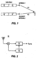
- the first data field having a first portion, D 1 , and a second portion, D 2 , is transmitted by the first antenna.
- a second data field is produced by modifying the first data field.
- the negation of the conjugate of D 2 , -D 2 *, is the first portion of the second data field and the conjugate of D 1 , D 1 *, is the second portion.
- the second data field is simultaneously transmitted by the second antenna.
- receivers for this scheme are still very complex.
- Such receivers utilize two joint detection devices. Each joint detection device recovers the data field transmitted from one of the antennas individually. Such an implementation deals with cross interference between the two transmitted data fields by dealing with each antenna's transmission separately. As a result, each joint detection device treats the other antenna's transmission as noise. The symbols recovered from each joint detection device are combined using a decoder to determine d ⁇ 1 and d ⁇ 2 .
- a block diagram of this system is illustrated in Figure 1. The receiver in such a system has a high complexity due to the use of two joint detectors resulting in higher receiver expense.
- EP-A-1069707 discloses a space time transmit diversity scheme using two antenna in which a data block of symbols is transmitted simultaneously with a complex conjugate of another block.
- H.R. Karimi "Efficient multi-rate multi-user detection for the asynchronous WCDMA uplink", 1999, ISBN 0-7803-5436-2, discloses a comparison between two approaches for reducing complexity of multi-user joint-detection techniques, one based on an approximate Cholesky factorization and one based on iterative schemes such as the method of conjugate gradients or the Jacobi algorithm and its derivatives.
- the present invention is a method and system for receiving data transmitted using block space time transmit diversity (BSTTD) in a code division multiple access (CDMA) communication system.
- the system comprises a transmitter for transmitting a first data field using a first antenna and a second data field using a second antenna and a receiver.
- the receiver includes an antenna for receiving the first and second transmitted data fields, and a BSTTD joint detector which determines symbols of the first and second transmitted data fields using a minimum mean square error block linear equalizer model and an approximated Cholesky decomposition of the model.
- Figure 1 is a block diagram of a prior art communication system employing space-time transmit diversity.
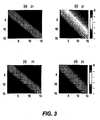
- FIG. 2 is a block diagram of a receiver in accordance with the preferred embodiment of the present invention.
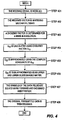
- FIG. 3 is an illustration of matrix structures for approximation of Block Space Time Transmit Diversity (BSTTD) in accordance with the preferred embodiment.
- BSTTD Block Space Time Transmit Diversity
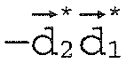
- Figure 4 is a flow diagram of the block space time transmit diversity joint detection method in accordance with the preferred embodiment.
- FIG. 2 is a block diagram of a receiver 10, preferably located at a user equipment (UE), in a CDMA communication system in accordance with the preferred embodiment of the present invention.
- the receiver 10 may be located at the base station and operating on uplink communications.
- the receiver 10 comprises a BSTTD joint detection device (BSTTD JD) 12, a channel estimation device 13 and an antenna 16.
- BSTTD JD BSTTD joint detection device
- the antenna 16 of the UE receives various RF signals including a first and second communication burst from a transmitter.
- the first and second communication bursts comprise the first and second data fields, respectively as described above.
- the first data field includes the first portion D 1 and the second portion D2; the second data field includes the negative conjugate of D2, -D2* and the conjugate of D1, D1*.
- a typical communication burst has the two portions of the data fields separated by a midamble. The burst also has a guard period at the end of it to allow for different times of arrival between bursts.
- Each data field of one communication burst is encoded as the first data field, D1, D2.
- Each data field of the other communication burst is encoded as the second data field, - D2*, D1*.
- the respective data fields are spread and a midamble included to produce the first and second communication bursts, respectively.
- Each of the communication bursts are transmitted by a respective first and second antenna in a RF signal to the receiver 10.
- the received RF communication signal including the first and second communication bursts is demodulated and forwarded to the channel estimation device 13 and BSTTD JD 12.
- the channel estimation device 13 processes the demodulated signal and forwards the channel information to the BSTTD JD 12.
- the BSTTD JD 12 receives the demodulated signal including the first and second communication bursts and the channel information from the channel estimation device 13. Using the channel information and the spreading codes of the transmitter, the BSTTD JD 12 estimates the data symbols of the first and second data fields of each communication burst, D1, D2, -D2*, -D1 and combines D1, D2, -D2*,-D1 to recover the original data field D.
- the BSTTD JD 12 estimates the data symbols of each of the received data fields utilizing a simplified minimum mean square error block linear equalizer (MMSE-BLE) based detector.
- MMSE-BLE simplified minimum mean square error block linear equalizer
- the BSTTD JD 12 of the present invention operates in accordance with the following.
- a and B are block banded versions of the propagation matrices of channel 1, associated with antenna 1, and channel 2, associated with antenna 2, respectively. They are rewritten as a 2x2 block matrix as follows.
- A A 11 0 A 21 A 22
- B B 11 0 B 21 B 22 .
- the received signal model for block space time transmit diversity is expressed as Equation 1.
- r ⁇ 1 r ⁇ 2 * A 11 0 0 - B 11 B 22 * - B 21 * A 21 * A 22 * ⁇ d ⁇ 1 d ⁇ 2 d ⁇ 1 * d ⁇ 2 * + n ⁇ 1 n ⁇ 2 * .
- Equation 5 The MMSE-BLE output is represented as Equation 5.
- d ⁇ mmse ⁇ 1 d ⁇ mmse ⁇ 2 * E H ⁇ E + ⁇ 2 ⁇ I - 1 d ⁇ wmf ⁇ 1 d ⁇ wmf ⁇ 2 * E is shown in Equation 2.
- ⁇ 2 is the mean noise variance and I is the identity matrix.
- the major complexity for block STTD is due to the matrix inversion, which is preferably implemented with an approximate Cholesky decomposition.
- the block matrix representation of the correlation matrix for Cholesky decomposition is written as Equation 6.
- D 11 A 11 H ⁇ A 11 + B 22 H ⁇ B 22 * + ⁇ 2 ⁇ I
- D 22 B 11 H ⁇ B 11 + A 22 H ⁇ A 22 * + ⁇ 2 ⁇ I
- D 21 A 22 H ⁇ B 22 * - B 11 H ⁇ A 11 .
- G G 11 0
- G 21 G 22 Equations 11, 12 and 13 are relationships between G 11 , G 21 , G 22 , D 11 , D 21 and D 22 .
- G 11 ⁇ G 11 H D 11
- G 21 ⁇ G 11 H D 21
- G 22 ⁇ G 22 H D 22 - G 21 ⁇ G 21 H
- the estimated symbol sequence can be obtained by solving the following triangular systems per Equations 14, 15, 16 and 17.
- G 11 ⁇ m ⁇ 1 d ⁇ wmf ⁇ 1
- G 22 ⁇ m ⁇ 2 d ⁇ wmf ⁇ 2 * - G 21 ⁇ m ⁇ 1
- G 22 H ⁇ d ⁇ mmse ⁇ 2 * m ⁇ 2
- G 11 H ⁇ d ⁇ mmse ⁇ 1 m ⁇ 1 - G 21 H ⁇ d ⁇ mmse ⁇ 2 *
- a 22 and B 22 can be represented by the block matrix forms with A 11 and B 11 as follows.
- a 22 H ⁇ B 22 A 11 H ⁇ B 11 + 0 0 0 A 3 H ⁇ B 3
- a 22 H A 22 H , B 22 H B 22 H and A 22 H B 22 H are the block Toeplitz matrices, but A 11 H A 11 , B 11 H B 11 and A 11 H B 11 are not because ofthe lower right sub-blocks in the last terms of the Equations 18, 19 and 20.
- Equation 4 by substituting Equation 18, becomes Equation 21.
- D 11 A 22 H ⁇ A 22 + B 22 H ⁇ B 22 * + ⁇ 2 ⁇ I - 0 0 0
- a 3 H ⁇ A 3 Equation 21 is block Hermitian.
- the solution of the Equation 7 can be approximated by the repeated version of Cholesky decomposition by ignoring the last term, i.e., Equation 22.
- D ⁇ 11 A 22 H ⁇ A 22 + B 22 H ⁇ B 22 * + ⁇ 2 ⁇ I Equation 22 is the block Toeplitz matrix approximation. Its complexity is equivalent to the approximated decomposition in the single antenna case. Those skilled in the art will recognize that the above equations result in an approximation of G 11 , reducing the complexity of the BSTTD JD 12.
- Equation 13 becomes Equation 24.
- G 22 ⁇ G 22 H D 22 - D 21 ⁇ D 11 - 1 ⁇ D 21 H
- Equation 24 becomes Equation 25.
- Equation 26 results.
- D 22 D ⁇ 11 * - 0 0 0 B 3 H ⁇ B 3
- Equations 15 and 17 The major complexity of BSTTD over single antenna is associated with matrix G 21 the Equations 12, 15 and 17.
- the number of complex operations in Equations 15 and 17 is the same as the nonzero elements of G 21 .
- Equation 28 results.
- G ⁇ 21 ⁇ G ⁇ 11 H D ⁇ 21 D ⁇ 22 is per Equation 29.
- D ⁇ 21 A 22 H ⁇ B 22 * - B 22 H ⁇ A 22
- Equation 29 results in a block Toeplitz matrix. Its general solution, though, is too complex to be readily implemented due to its multiple forward triangular system solutions. However, it can be simplified using the following properties:
- the simplified ⁇ 21 can be represented by: f 11 f 12 ⁇ f 1 ⁇ L 0 ⁇ ⁇ 0 f 21 f 11 f 12 ⁇ f 1 ⁇ L 0 ⁇ ⁇ f 21 f 11 ⁇ ⁇ ⁇ f L ⁇ 1 ⁇ ⁇ ⁇ 0 0 f L ⁇ 1 f 1 ⁇ L ⁇ 0 ⁇ ⁇ ⁇ ⁇ ⁇ ⁇ f 11 f 12 0 ⁇ ⁇ 0 f L ⁇ 1 ⁇ f 21 f 11
- Equations 30 and 31 The block matrix representations of the correlation matrix D ⁇ 21 and lower triangular matrix ⁇ 21 are written as Equations 30 and 31.
- the first K d element at the last column vector is obtained by the division of the complex number to the real number as per Equation 34.
- Equation 33 contains matrix multiplications.
- Each matrix multiplication can be considered as K d +( K d +1) 2 complex multipliers due to the zero elements.
- the received signal is modelled by ignoring the interference between data blocks, such as per Equation 2 (Step 401).
- the received vector is whitening matched filtered, such as per Equations 3 and 4 (Step 402).
- a Cholesky factor of the form of Equation 10 is determined for a MMSE BLE solution (Step 403).
- a sub-matrix of G, G 11 is then calculated by calculating a Cholesky factor of a sub-matrix of D, D 11 (of Equation 7), as per Equation 22 (Step 404).
- Step 405 Another approximation of a sub-matrix ofG, G 22 , using the complex conjugate of G 11 , G 11 *, per Equation 26 is calculated (Step 405).
- Another sub-matrix of G, G21 is approximated as being an upper and lower block banded matrix using Equations 31 and 32 (Step 406).
- the symbols of the two data fields, d ⁇ mmse 1 and d ⁇ mmse 2 are solved using forward and backward substitution per Equations 35, 36, 37 and 38 (Step 407).
- the original transmitted data is then determined by decoding d ⁇ mmse 1 and d ⁇ mmse 2 using decoder 15 (Step 408).
Landscapes
- Engineering & Computer Science (AREA)
- Computer Networks & Wireless Communication (AREA)
- Signal Processing (AREA)
- Radio Transmission System (AREA)
Claims (9)
- Verfahren zum Empfangen von Datenfeldern, die unter Verwendung von Block-Raum-Zeit-Sendediversität BSTTD in einem Codemultiplex-Vielfachzugriff-CDMA-Kommunikationssystem gesendet werden, wobei die Übertragung durchgeführt wird, indem ein erstes Datenfeld (

 Empfangen des ersten Datenfelds und des zweiten Datenfelds ;gekennzeichnet durch:Erzeugen (401) eines Interferenz zwischen den Datenblöcken ignorierenden Empfangssignalmodells gemäß:wobei A und B Blockbandversionen der jeweils zu der ersten und zweiten Antenne gehörenden Ausbreitungsmatrizen sind; und Bestimmen übertragener Datensymbole des ersten Datenfelds und des zweiten Datenfelds unter Verwendung linearer Blockentzerrung mit minimalem mittleren Quadratfehler, genäherter Cholesky-Zerlegung (403) und Vorwärts- und Rückwärtssubstitution (407), wobei ein in der genäherten Cholesky-Zerlegung verwendeter Cholesky-Faktor vier Blockmatrizen aufweist, wobei ein erster Block der vier Blockmatrizen als eine komplex Konjugierte eines zweiten Blocks der vier Blockmatrizen genähert wird (405).
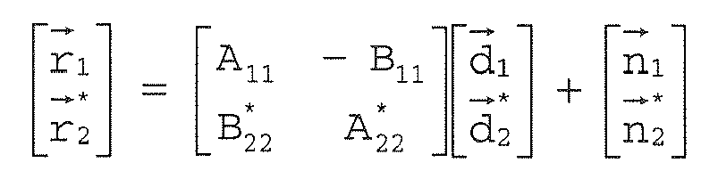
- Verfahren nach Anspruch 1, wobei die empfangenen Datenfelder durch ein angepaßtes Analysefilter (Whitening-Filter) verarbeitet werden.
- Verfahren nach Anspruch 2, wobei die empfangenen Datenfelder durch eine Kanalschätzvorrichtung verarbeitet werden, welche Kanalinformationen erzeugt, die zur Bestimmung von übertragenen Datensymbolen verwendet werden sollen.
- Empfänger zum Wiedergewinnen von Datenfeldern, die von einem Block-Raum-Zeit-Sendediversitäts-BSTTD-Sender gesendet werden, der ein erstes Datenfeld (

 eine Antenne zum Empfangen eines Vektors, der sowohl das erste Datenfeld als auch das zweite Datenfeld aufweist; und gekennzeichnet durch:wobei A und B Blockbandversionen der jeweils zu der ersten und zweiten Antenne gehörenden Ausbreitungsmatrizen sind, und wobei ein in der genäherten Cholesky-Zerlegung verwendeter Cholesky-Faktor vier Blockmatrizen umfaßt, wobei ein erster Block der vier Blockmatrizen als eine komplex Konjugierte eines zweiten Blocks der vier Blockmatrizen genähert wird (405).einen BSTTD-Joint-Detector zum Bestimmen übertragener Symbole des ersten Datenfelds und des zweiten Datenfelds unter Verwendung linearer Blockentzerrung mit minimalem mittleren Quadratfehler, genäherter Cholesky-Zerlegung (403) und Vorwärts- und Rückwärtssubstitution (407), wobei ein Empfangssignalmodell (401), das Interferenz zwischen den Datenblöcken ignoriert, verwendet wird, gemäß:
- Empfänger nach Anspruch 4, der ferner ein angepaßtes Analysefilter (Whitening-Filter) zum Verarbeiten der empfangenen Datenfelder aufweist.
- Empfänger nach Anspruch 5, der ferner eine Kanalschätzvorrichtung zum Erzeugen von Kanalinformationen aufweist.
- CDMA-Kommunikationssystem zum Wiedergewinnen von Datenfeldern, die unter Verwendung von Block-Raum-Zeit-Sendediversität BSTTD gesendet werden, wobei das System aufweist:einen Sender, der ein erstes Datenfeld (
 einen Empfänger zum Empfangen von Datenfeldern, die unter Verwendung der BSTTD gesendet wurden, der aufweist:wobei A und B Blockbandversionen der jeweils zu der ersten und zweiten Antenne gehörenden Ausbreitungsmatrizen sind, und wobei ein in der genäherten Cholesky-Zerlegung verwendeter Cholesky-Faktor vier Blockmatrizen umfaßt, wobei ein erster Block der vier Blockmatrizen als eine komplex Konjugierte eines zweiten Blocks der vier Blockmatrizen genähert wird (405).eine Antenne zum Empfangen eines Vektors, der sowohl das erste Datenfeld als auch das zweite Datenfeld aufweist; und gekennzeichnet durch:einen BSTTD-Joint-Detector, der lineare Blockentzerrung mit minimalem mittleren Quadratfehler, genäherte Cholesky-Zerlegung (403) und Vorwärts- und Rückwärtssubstitution (407) verwendet, um Symbole des ersten Datenfelds und des zweiten Datenfelds zu bestimmen, wobei er ein Empfangssignalmodell verwendet, das Interferenz zwischen den Datenblöcken ignoriert, gemäß:
- System nach Anspruch 7, das ferner ein angepaßtes Analysefilter (Whitening-Filter) zum Verarbeiten der empfangenen Datenfelder aufweist.
- System nach Anspruch 8, das ferner eine Kanalschätzvorrichtung zum Erzeugen von Kanalinformationen aufweist.
Applications Claiming Priority (5)
| Application Number | Priority Date | Filing Date | Title |
|---|---|---|---|
| US26391501P | 2001-01-25 | 2001-01-25 | |
| US263915P | 2001-01-25 | ||
| US34793 | 2001-12-27 | ||
| US10/034,793 US6707864B2 (en) | 2001-01-25 | 2001-12-27 | Simplified block linear equalizer with block space time transmit diversity |
| EP02714751A EP1354424A2 (de) | 2001-01-25 | 2002-01-18 | Vereinfachter block-linearer entzerrer mit mit raum-zeit sende-diversität |
Related Parent Applications (1)
| Application Number | Title | Priority Date | Filing Date |
|---|---|---|---|
| EP02714751A Division EP1354424A2 (de) | 2001-01-25 | 2002-01-18 | Vereinfachter block-linearer entzerrer mit mit raum-zeit sende-diversität |
Publications (3)
| Publication Number | Publication Date |
|---|---|
| EP1560347A1 EP1560347A1 (de) | 2005-08-03 |
| EP1560347B1 true EP1560347B1 (de) | 2007-04-25 |
| EP1560347B8 EP1560347B8 (de) | 2007-09-19 |
Family
ID=34657530
Family Applications (1)
| Application Number | Title | Priority Date | Filing Date |
|---|---|---|---|
| EP05100393A Expired - Lifetime EP1560347B8 (de) | 2001-01-25 | 2002-01-18 | Vereinfachter Block-Linearer Entzerrer mit Raum-Zeit Sende-Diversität |
Country Status (1)
| Country | Link |
|---|---|
| EP (1) | EP1560347B8 (de) |
Families Citing this family (1)
| Publication number | Priority date | Publication date | Assignee | Title |
|---|---|---|---|---|
| DE602006018942D1 (de) * | 2006-10-11 | 2011-01-27 | Thomson Licensing | Verfahren zur Dekodierung eines empfangenen multidimensionalen Signals und entsprechende Vorrichtung |
Family Cites Families (1)
| Publication number | Priority date | Publication date | Assignee | Title |
|---|---|---|---|---|
| EP1069707A1 (de) * | 1999-07-13 | 2001-01-17 | Motorola, Inc. | Sende-Diversity-Sender und -Empfänger für Radio-Kommunikationssystem |
-
2002
- 2002-01-18 EP EP05100393A patent/EP1560347B8/de not_active Expired - Lifetime
Non-Patent Citations (1)
| Title |
|---|
| None * |
Also Published As
| Publication number | Publication date |
|---|---|
| EP1560347A1 (de) | 2005-08-03 |
| EP1560347B8 (de) | 2007-09-19 |
Similar Documents
| Publication | Publication Date | Title |
|---|---|---|
| US7489721B2 (en) | Simplified block linear equalizer with block space time transmit diversity | |
| US7170926B2 (en) | Efficient multiple input multiple output system for multi-path fading channels | |
| US7796678B2 (en) | Communication system with receivers employing generalized two-stage data estimation | |
| EP1686696B1 (de) | Einzelbenutzerdetektion | |
| US20070280336A1 (en) | Constrained Optimization Based Mimo Lmmse-Sic Receiver for Cdma Downlink | |
| EP1533928B1 (de) | Verfahren zur raum-zeit-kodierung/dekodierung für frequenzselektiven schwundkanal | |
| US7095731B2 (en) | Modified block space time transmit diversity encoder | |
| EP2073402A2 (de) | Schätzgerät für erweiterten Algorithmus | |
| IL148649A (en) | Shared identification of multiple user signals in a wireless communication system | |
| EP1560347B1 (de) | Vereinfachter Block-Linearer Entzerrer mit Raum-Zeit Sende-Diversität | |
| CN100446434C (zh) | 接收数据的方法及其接收器和无线通信系统 | |
| EP1650892A1 (de) | Modifizierter Raum-Zeit Block-Sendediversitätsdekodierer | |
| AU2006201932A1 (en) | Efficient Multiple Input Multiple Output System for Multi-Path Fading Channels |
Legal Events
| Date | Code | Title | Description |
|---|---|---|---|
| PUAI | Public reference made under article 153(3) epc to a published international application that has entered the european phase |
Free format text: ORIGINAL CODE: 0009012 |
|
| 17P | Request for examination filed |
Effective date: 20050121 |
|
| AC | Divisional application: reference to earlier application |
Ref document number: 1354424 Country of ref document: EP Kind code of ref document: P |
|
| AK | Designated contracting states |
Kind code of ref document: A1 Designated state(s): AT BE CH CY DE DK ES FI FR GB GR IE IT LI LU MC NL PT SE TR |
|
| AKX | Designation fees paid |
Designated state(s): AT BE CH CY DE DK ES FI FR GB GR IE IT LI LU MC NL PT SE TR |
|
| GRAP | Despatch of communication of intention to grant a patent |
Free format text: ORIGINAL CODE: EPIDOSNIGR1 |
|
| GRAS | Grant fee paid |
Free format text: ORIGINAL CODE: EPIDOSNIGR3 |
|
| GRAA | (expected) grant |
Free format text: ORIGINAL CODE: 0009210 |
|
| AC | Divisional application: reference to earlier application |
Ref document number: 1354424 Country of ref document: EP Kind code of ref document: P |
|
| AK | Designated contracting states |
Kind code of ref document: B1 Designated state(s): AT BE CH CY DE DK ES FI FR GB GR IE IT LI LU MC NL PT SE TR |
|
| PG25 | Lapsed in a contracting state [announced via postgrant information from national office to epo] |
Ref country code: LI Free format text: LAPSE BECAUSE OF FAILURE TO SUBMIT A TRANSLATION OF THE DESCRIPTION OR TO PAY THE FEE WITHIN THE PRESCRIBED TIME-LIMIT Effective date: 20070425 Ref country code: CH Free format text: LAPSE BECAUSE OF FAILURE TO SUBMIT A TRANSLATION OF THE DESCRIPTION OR TO PAY THE FEE WITHIN THE PRESCRIBED TIME-LIMIT Effective date: 20070425 |
|
| REG | Reference to a national code |
Ref country code: GB Ref legal event code: FG4D |
|
| RAP2 | Party data changed (patent owner data changed or rights of a patent transferred) |
Owner name: INTERDIGITAL PATENT CORPORATION |
|
| RAP2 | Party data changed (patent owner data changed or rights of a patent transferred) |
Owner name: INTERDIGITAL TECHNOLOGY CORPORATION |
|
| REG | Reference to a national code |
Ref country code: SE Ref legal event code: TRGR |
|
| REG | Reference to a national code |
Ref country code: IE Ref legal event code: FG4D |
|
| REG | Reference to a national code |
Ref country code: CH Ref legal event code: EP |
|
| REF | Corresponds to: |
Ref document number: 60219834 Country of ref document: DE Date of ref document: 20070606 Kind code of ref document: P |
|
| REG | Reference to a national code |
Ref country code: GB Ref legal event code: ERR Free format text: NOTIFICATION HAS NOW BEEN RECEIVED FROM THE EUROPEAN PATENT OFFICE THAT THE CORRECT NAME IS: INTERDIGITAL TECHNOLOGY CORPORATION THIS CORRECTION WAS PUBLISHED IN THE EUROPEAN PATENT BULLETIN 07/19 DATED 20070509 |
|
| NLT2 | Nl: modifications (of names), taken from the european patent patent bulletin |
Owner name: INTERDIGITAL TECHNOLOGY CORPORATION Effective date: 20070509 Owner name: INTERDIGITAL PATENT CORPORATION Effective date: 20070502 |
|
| ET | Fr: translation filed | ||
| PG25 | Lapsed in a contracting state [announced via postgrant information from national office to epo] |
Ref country code: PT Free format text: LAPSE BECAUSE OF FAILURE TO SUBMIT A TRANSLATION OF THE DESCRIPTION OR TO PAY THE FEE WITHIN THE PRESCRIBED TIME-LIMIT Effective date: 20070925 |
|
| REG | Reference to a national code |
Ref country code: CH Ref legal event code: PL |
|
| NLV1 | Nl: lapsed or annulled due to failure to fulfill the requirements of art. 29p and 29m of the patents act | ||
| REG | Reference to a national code |
Ref country code: ES Ref legal event code: FG2A Ref document number: 2284122 Country of ref document: ES Kind code of ref document: T3 |
|
| PG25 | Lapsed in a contracting state [announced via postgrant information from national office to epo] |
Ref country code: AT Free format text: LAPSE BECAUSE OF FAILURE TO SUBMIT A TRANSLATION OF THE DESCRIPTION OR TO PAY THE FEE WITHIN THE PRESCRIBED TIME-LIMIT Effective date: 20070425 |
|
| PG25 | Lapsed in a contracting state [announced via postgrant information from national office to epo] |
Ref country code: BE Free format text: LAPSE BECAUSE OF FAILURE TO SUBMIT A TRANSLATION OF THE DESCRIPTION OR TO PAY THE FEE WITHIN THE PRESCRIBED TIME-LIMIT Effective date: 20070425 |
|
| PG25 | Lapsed in a contracting state [announced via postgrant information from national office to epo] |
Ref country code: DK Free format text: LAPSE BECAUSE OF FAILURE TO SUBMIT A TRANSLATION OF THE DESCRIPTION OR TO PAY THE FEE WITHIN THE PRESCRIBED TIME-LIMIT Effective date: 20070425 Ref country code: NL Free format text: LAPSE BECAUSE OF FAILURE TO SUBMIT A TRANSLATION OF THE DESCRIPTION OR TO PAY THE FEE WITHIN THE PRESCRIBED TIME-LIMIT Effective date: 20070425 |
|
| PGFP | Annual fee paid to national office [announced via postgrant information from national office to epo] |
Ref country code: MC Payment date: 20071224 Year of fee payment: 7 |
|
| PLBE | No opposition filed within time limit |
Free format text: ORIGINAL CODE: 0009261 |
|
| STAA | Information on the status of an ep patent application or granted ep patent |
Free format text: STATUS: NO OPPOSITION FILED WITHIN TIME LIMIT |
|
| 26N | No opposition filed |
Effective date: 20080128 |
|
| PG25 | Lapsed in a contracting state [announced via postgrant information from national office to epo] |
Ref country code: GR Free format text: LAPSE BECAUSE OF FAILURE TO SUBMIT A TRANSLATION OF THE DESCRIPTION OR TO PAY THE FEE WITHIN THE PRESCRIBED TIME-LIMIT Effective date: 20070726 |
|
| PGFP | Annual fee paid to national office [announced via postgrant information from national office to epo] |
Ref country code: IE Payment date: 20080111 Year of fee payment: 7 Ref country code: LU Payment date: 20080114 Year of fee payment: 7 |
|
| PG25 | Lapsed in a contracting state [announced via postgrant information from national office to epo] |
Ref country code: CY Free format text: LAPSE BECAUSE OF FAILURE TO SUBMIT A TRANSLATION OF THE DESCRIPTION OR TO PAY THE FEE WITHIN THE PRESCRIBED TIME-LIMIT Effective date: 20070425 |
|
| PG25 | Lapsed in a contracting state [announced via postgrant information from national office to epo] |
Ref country code: MC Free format text: LAPSE BECAUSE OF NON-PAYMENT OF DUE FEES Effective date: 20090131 |
|
| PG25 | Lapsed in a contracting state [announced via postgrant information from national office to epo] |
Ref country code: IE Free format text: LAPSE BECAUSE OF NON-PAYMENT OF DUE FEES Effective date: 20090119 |
|
| PG25 | Lapsed in a contracting state [announced via postgrant information from national office to epo] |
Ref country code: TR Free format text: LAPSE BECAUSE OF FAILURE TO SUBMIT A TRANSLATION OF THE DESCRIPTION OR TO PAY THE FEE WITHIN THE PRESCRIBED TIME-LIMIT Effective date: 20070425 |
|
| PG25 | Lapsed in a contracting state [announced via postgrant information from national office to epo] |
Ref country code: LU Free format text: LAPSE BECAUSE OF NON-PAYMENT OF DUE FEES Effective date: 20090118 |
|
| PGFP | Annual fee paid to national office [announced via postgrant information from national office to epo] |
Ref country code: ES Payment date: 20131211 Year of fee payment: 13 |
|
| PGFP | Annual fee paid to national office [announced via postgrant information from national office to epo] |
Ref country code: SE Payment date: 20140113 Year of fee payment: 13 Ref country code: FI Payment date: 20140110 Year of fee payment: 13 Ref country code: DE Payment date: 20140115 Year of fee payment: 13 |
|
| PGFP | Annual fee paid to national office [announced via postgrant information from national office to epo] |
Ref country code: FR Payment date: 20140108 Year of fee payment: 13 Ref country code: IT Payment date: 20140120 Year of fee payment: 13 |
|
| PGFP | Annual fee paid to national office [announced via postgrant information from national office to epo] |
Ref country code: GB Payment date: 20140115 Year of fee payment: 13 |
|
| REG | Reference to a national code |
Ref country code: DE Ref legal event code: R119 Ref document number: 60219834 Country of ref document: DE |
|
| REG | Reference to a national code |
Ref country code: SE Ref legal event code: EUG |
|
| GBPC | Gb: european patent ceased through non-payment of renewal fee |
Effective date: 20150118 |
|
| PG25 | Lapsed in a contracting state [announced via postgrant information from national office to epo] |
Ref country code: GB Free format text: LAPSE BECAUSE OF NON-PAYMENT OF DUE FEES Effective date: 20150118 Ref country code: FI Free format text: LAPSE BECAUSE OF NON-PAYMENT OF DUE FEES Effective date: 20150118 Ref country code: DE Free format text: LAPSE BECAUSE OF NON-PAYMENT OF DUE FEES Effective date: 20150801 |
|
| REG | Reference to a national code |
Ref country code: FR Ref legal event code: ST Effective date: 20150930 |
|
| PG25 | Lapsed in a contracting state [announced via postgrant information from national office to epo] |
Ref country code: FR Free format text: LAPSE BECAUSE OF NON-PAYMENT OF DUE FEES Effective date: 20150202 Ref country code: SE Free format text: LAPSE BECAUSE OF NON-PAYMENT OF DUE FEES Effective date: 20150119 |
|
| PG25 | Lapsed in a contracting state [announced via postgrant information from national office to epo] |
Ref country code: IT Free format text: LAPSE BECAUSE OF NON-PAYMENT OF DUE FEES Effective date: 20150118 |
|
| REG | Reference to a national code |
Ref country code: ES Ref legal event code: FD2A Effective date: 20160226 |
|
| PG25 | Lapsed in a contracting state [announced via postgrant information from national office to epo] |
Ref country code: ES Free format text: LAPSE BECAUSE OF NON-PAYMENT OF DUE FEES Effective date: 20150119 |