EP1560283A1 - Electrode structure for solid polymer type fuel cell - Google Patents
Electrode structure for solid polymer type fuel cell Download PDFInfo
- Publication number
- EP1560283A1 EP1560283A1 EP03756719A EP03756719A EP1560283A1 EP 1560283 A1 EP1560283 A1 EP 1560283A1 EP 03756719 A EP03756719 A EP 03756719A EP 03756719 A EP03756719 A EP 03756719A EP 1560283 A1 EP1560283 A1 EP 1560283A1
- Authority
- EP
- European Patent Office
- Prior art keywords
- diffusion layer
- water
- layer
- anode
- cathode
- Prior art date
- Legal status (The legal status is an assumption and is not a legal conclusion. Google has not performed a legal analysis and makes no representation as to the accuracy of the status listed.)
- Withdrawn
Links
Images


Classifications
-
- H—ELECTRICITY
- H01—ELECTRIC ELEMENTS
- H01M—PROCESSES OR MEANS, e.g. BATTERIES, FOR THE DIRECT CONVERSION OF CHEMICAL ENERGY INTO ELECTRICAL ENERGY
- H01M8/00—Fuel cells; Manufacture thereof
- H01M8/10—Fuel cells with solid electrolytes
- H01M8/1004—Fuel cells with solid electrolytes characterised by membrane-electrode assemblies [MEA]
-
- H—ELECTRICITY
- H01—ELECTRIC ELEMENTS
- H01M—PROCESSES OR MEANS, e.g. BATTERIES, FOR THE DIRECT CONVERSION OF CHEMICAL ENERGY INTO ELECTRICAL ENERGY
- H01M4/00—Electrodes
- H01M4/86—Inert electrodes with catalytic activity, e.g. for fuel cells
- H01M4/8605—Porous electrodes
-
- H—ELECTRICITY
- H01—ELECTRIC ELEMENTS
- H01M—PROCESSES OR MEANS, e.g. BATTERIES, FOR THE DIRECT CONVERSION OF CHEMICAL ENERGY INTO ELECTRICAL ENERGY
- H01M4/00—Electrodes
- H01M4/86—Inert electrodes with catalytic activity, e.g. for fuel cells
- H01M4/8647—Inert electrodes with catalytic activity, e.g. for fuel cells consisting of more than one material, e.g. consisting of composites
- H01M4/8657—Inert electrodes with catalytic activity, e.g. for fuel cells consisting of more than one material, e.g. consisting of composites layered
-
- H—ELECTRICITY
- H01—ELECTRIC ELEMENTS
- H01M—PROCESSES OR MEANS, e.g. BATTERIES, FOR THE DIRECT CONVERSION OF CHEMICAL ENERGY INTO ELECTRICAL ENERGY
- H01M4/00—Electrodes
- H01M4/86—Inert electrodes with catalytic activity, e.g. for fuel cells
- H01M4/90—Selection of catalytic material
- H01M4/92—Metals of platinum group
- H01M4/925—Metals of platinum group supported on carriers, e.g. powder carriers
- H01M4/926—Metals of platinum group supported on carriers, e.g. powder carriers on carbon or graphite
-
- Y—GENERAL TAGGING OF NEW TECHNOLOGICAL DEVELOPMENTS; GENERAL TAGGING OF CROSS-SECTIONAL TECHNOLOGIES SPANNING OVER SEVERAL SECTIONS OF THE IPC; TECHNICAL SUBJECTS COVERED BY FORMER USPC CROSS-REFERENCE ART COLLECTIONS [XRACs] AND DIGESTS
- Y02—TECHNOLOGIES OR APPLICATIONS FOR MITIGATION OR ADAPTATION AGAINST CLIMATE CHANGE
- Y02E—REDUCTION OF GREENHOUSE GAS [GHG] EMISSIONS, RELATED TO ENERGY GENERATION, TRANSMISSION OR DISTRIBUTION
- Y02E60/00—Enabling technologies; Technologies with a potential or indirect contribution to GHG emissions mitigation
- Y02E60/30—Hydrogen technology
- Y02E60/50—Fuel cells
Definitions
- the present invention relates to a membrane electrode assembly for polymer electrolyte fuel cells, and in particular, relates to a membrane electrode assembly for polymer electrolyte fuel cell in which efficiency deterioration when there is a shortage of fuel is reduced.
- a unit of a polymer electrolyte fuel cell is formed by laminating separators at both sides of a tabular membrane electrode assembly (MEA), and then plural units are laminated to form a fuel cell stack.
- MEA tabular membrane electrode assembly
- the membrane electrode assembly is a layered structure in which a polymer electrolyte membrane is arranged between a pair of gas diffusion electrodes forming a cathode and an anode.
- the gas diffusion electrode is a structure in which a gas diffusion layer is formed on an outer surface of an electrode catalytic layer contacting the electrolyte membrane.
- the gas diffusion layer conducts electrons generated by the electric chemical reaction between the electrode catalytic layer and the separator, and at the same time, diffuses fuel gas and oxidizing gas.
- Protons (H + ) and electrons are generated from the fuel gas in the anode electrode catalytic layer, water is generated from oxygen, protons, and electrons in the cathode electrode catalytic layer, and protons are ion conducted through the electrolyte membrane.
- electric power can be obtained between the electrode catalytic layers of cathode and anode.
- Patent Application Publication No. 01/15254 a technique in which corrosion resistance of carbon is improved by increasing supported ratio of catalyst or by using carbon having higher corrosion resistance is disclosed in Patent Application Publication No. 01/15254. Furthermore, from the viewpoint of the above reaction of formula (1), a technique in which catalyst promoting electrolysis of water is added to the anode catalytic layer (Patent Application Publications No. 01/15247 and No. 01/15255), a technique in which material to increase water amount is added to the anode catalytic layer or diffusion layer (Patent Application Publications No. 01/15255 and No. 01/15249) or the like are disclosed.
- the conventional techniques mentioned above are effective in a temporary fuel shortage; however, in the case in which fuel shortage occurs repeatedly in practical operations or in the case of a rated operation, there is a problem of the flooding phenomenon.
- Flooding is a phenomenon in which micropores of gas diffusion flow passage in the anode catalytic layer are filled with water, and therefore gas diffusion is inhibited.
- the flooding inhibits supply of fuel gas, enlarges the area of fuel shortage in the anode (fuel gas electrode), and promotes corrosion reaction of carbon, and as a result, deteriorates efficiency of the membrane electrode assembly.
- An object of the present invention is to provide a membrane electrode assembly for polymer electrolyte fuel cell in which efficiency deterioration at shortage of fuel is restrained.
- the anode diffusion layer has characteristics (1) to (3) below.
- the anode catalytic layer does not have a water holding property; however, the water holding layer in which water holding material is contained at 5 to 20 wt% to the total amount of the electron conductive material and the water holding material, is arranged on the carbon-based material, or alternatively, carbon particles having water absorption amount at saturated water vapor pressure at 60°C is not less than 150 cc/g, are contained. Therefore, water absorption ratio of the anode diffusion layer at 60°C is in a range of 40 to 85%, and the anode diffusion layer has high water holding property.
- water is supplied from the anode diffusion layer to the anode catalytic layer, the water is electrolyzed in the anode catalytic layer, protons are supplied to the polymer electrolyte membrane.
- the anode diffusion layer has characteristics (1) to (4) below.
- the anode catalytic layer does not have a water holding property; however, a carbon-based material of the anode diffusion layer is processed to be hydrophilic, and that carbon particles having water absorption amount at saturated water vapor pressure at 60°C of not less than 150 cc/g, are contained. Therefore, water absorption ratio of the anode diffusion layer at 60°C is in a range of 40 to 85%, and the anode diffusion layer has high water holding property.
- water is supplied from the anode diffusion layer to the anode catalytic layer, the water is electrolyzed in the anode catalytic layer, and protons are supplied to the polymer electrolyte membrane.
- a membrane electrode assembly for polymer electrolyte fuel cell of another desirable embodiment of the present invention having a polymer electrolyte membrane, and an anode and a cathode both having catalytic layers and diffusion layers:
- carbon particles having water absorption amount at saturated water vapor pressure at 60°C of not less than 150 cc/g are contained in the anode diffusion layer
- carbon particles having water absorption amount at saturated water vapor pressure at 60°C of not more than 150 cc/g are contained in the cathode diffusion layer
- water absorption ratio of the anode diffusion layer at 60°C is in a range of 40 to 85%. Therefore, amount of water of reverse diffusion from the cathode to the anode is increased, and water holding property of the anode diffusion layer is high.
- water is supplied from the anode diffusion layer to the anode catalytic layer, the water is electrolyzed in the anode catalytic layer, protons are supplied to the polymer electrolyte membrane.
- carbon-based material of the anode diffusion layer is processed to be hydrophilic and to have a contact angle with water of not more than 90°
- carbon-based material of the cathode diffusion layer is processed to be hydrophobic and to have a contact angle with water of not less than 130°.
- the anode diffusion layer can have high water holding property, reverse diffusion of generated water and supplied water from the cathode to the anode can be performed efficiently, electrolysis of water in the anode catalytic layer can be promoted, and corrosion reaction of carbon can be restrained more.
- the anode diffusion layer of membrane electrode assembly for polymer electrolyte fuel cell of the first and second embodiments of the present invention can be consist of (1) carbon-based material, (2) a layer containing carbon particles and fluorine resin arranged thereon, and (3) a layer containing carbon particles, polymer electrolyte, void forming agent, and water holding material further arranged thereon.
- it can be consist of (1) carbon-based material and (2) a layer containing carbon particles, fluorine resin, and water holding material arranged thereon.
- the anode diffusion layer of the present invention is required to have water absorption ratio at 60°C in a range of 40 to 85% by arranging water holding layer containing 5 to 20 wt% of water holding material which increases water holding property to the total amount of electron conductive material and water holding material, on the carbon-based material, or by containing carbon particles having water absorption amount at saturated water vapor pressure at 60°C of not less than 150 cc/g.
- Fig. 1 is a graph showing a relationship of content ratio of the water holding material to the total amount of electron conductive material and water holding material, and voltage decrease.
- Fig. 2 is a graph showing a relationship of water absorption amount of carbon particles and voltage decrease.
- Fig. 3 is a graph showing a relationship of water absorption ratio of the anode diffusion layer at 60°C and voltage decrease. As is clear from Fig. 3, if the water absorption ratio of the anode diffusion layer is in a range of 40 to 85%, voltage decrease is not more than 30 mV, and desirable voltage efficiency is exhibited.
- the content amount of the water holding material or water absorption amount of the carbon particles are below the range mentioned above, water absorption ratio of the anode diffusion layer is too low, and the above-mentioned effect cannot be obtained. If the content amount of the water holding material or water absorption amount of the carbon particles are above the range mentioned above, water absorption ratio of the anode diffusion layer is too high, gas supplying property is deteriorated by flooding phenomenon, and fuel shortage area is increased.
- oxides such as zeolite, ⁇ -alumina, or silica can be used.
- differential pressure measured by a differential pressure measuring method must be in a range of 60 to 120 mmaq.
- Fig. 4 is a graph showing a relationship of differential pressure of the anode diffusion layer and voltage decrease. As is clear from Fig. 4, if the differential pressure of the anode diffusion layer is in a range of 60 to 120 mmaq, voltage decrease is not more than 30 mV, and desirable voltage efficiency is exhibited. On the other hand, if the differential pressure is above 120 mmaq, gas supplying property is deteriorated, and fuel shortage area is increased. If the differential pressure is below 60 mmaq, supplying protons only by electrolysis of water is not sufficient since the water exhausting property is high, and corrosion reaction of carbon material in the anode is promoted.
- the differential pressure measuring method mentioned herein is a method in which anode diffusion layer is set and held at mid-stream of a gas flow passage, a pre-determined flow amount of reaction gas is flowed, pressures in front of and behind the anode diffusion layer are measured, and the difference in the pressures is calculated.
- adhesion ratio in the present invention is defined by the following formula.
- Adhesion ratio (%) (Measured value by cyclic voltammetric method under condition of one side humidified) / (Measured value by cyclic voltammetric method under condition of both side humidified) x 100
- the cyclic voltammetric method under conditions of both sides humidified as mentioned herein is a method in which humidified gas is supplied to both anode and cathode to humidify the entire electrode assembly and the amount of electric charge of all the catalytic material of all of the electrode catalytic layer depending on electrochemical surface area is measured.
- the cyclic voltammetric method under conditions of one side humidified as mentioned herein is a method in which humidified gas is supplied only from the anode, the water supplied from the anode is dispersed only to conductive passages of the polymer membrane of the cathode side, and the amount of electric charge of the catalytic material of the cathode catalytic layer existing from the polymer electrolyte membrane to proton conductive passages depending on electrochemical surface area is measured. If the amount of the catalytic material of the cathode catalytic layer existing from the polymer electrolyte membrane to proton conductive passages becomes larger, the adhesion ratio becomes larger and the catalytic material is effectively used.
- Fig. 5 is a graph showing a relationship of adhesion ratio and voltage decrease. As is clear from Fig. 5, if the adhesion ratio is not less than 15%, voltage decrease is not more than 30 mV, and desirable voltage efficiency is exhibited. Therefore, in the present invention, it is necessary that the ratio of quantity of electric charge of catalytic material of the cathode catalytic layer existing in proton conductive passage from the polymer electrolyte membrane measured by the cyclic voltammetric method be not less than 15% of the quantity of electric charge of all of the catalytic material existing in the cathode catalytic layer.
- a resistance overvoltage loss at 1 A/cm 2 be less than 10 mV.
- Fig. 6 is a graph showing the relationship of penetration resistance and voltage loss at 1 A/cm 2 . As is clear from Fig. 6, if the penetration resistance is not more than 5 m ⁇ , the voltage loss at 1 A/cm 2 is less than 10 mV, and desirable voltage efficiency is exhibited.
- carbon-based material of the anode diffusion layer in third embodiment is limited to the carbon material which is processed to be hydrophilic and not more than 90° of contact angle with water. It is necessary to prepare water absorption ratio of the anode diffusion layer at 60°C in a range of 40 to 85% by arranging a layer having fluorine resin and carbon particles whose water absorption amount at saturated water vapor pressure at 60°C is not less than 150 cc/g, on this carbon-based material.
- Fig.7 is a graph showing a relationship of contact angle of the carbon-based material with water and voltage decrease. As is clear from Figs.
- Fig. 8 is a graph showing a relationship of water absorption ratio of the anode diffusion layer at 60°C and the voltage decrease. Also in this embodiment, as is clear from Fig. 8, if the water absorption ratio of the anode diffusion layer is in a range of 40 to 85%, voltage decrease is not more than 30 mV, desirable voltage efficiency is exhibited.
- the contact angle of the carbon-based material is above the range, water absorbed in the anode diffusion layer goes to the anode catalytic layer, flooding phenomenon occurs in the anode catalytic layer, gas supplying property is deteriorated, and area of fuel shortage under fuel shortage conditions is enlarged.
- the water absorption amount of the carbon particles is below the range, the effect of the present invention cannot be obtained since the water absorption ratio is too low.
- the water absorption amount of the carbon particles is above the range, gas supplying property is deteriorated by the flooding phenomenon and area of fuel shortage under fuel shortage conditions is enlarged since the water absorption ratio of the anode diffusion layer is too high.
- Fig. 9 is a graph showing a relationship of the differential pressure of the anode diffusion layer and the voltage decrease.
- Fig. 10 is a graph showing a relationship of adhesion ratio and the voltage decrease in this embodiment.
- the adhesion ratio is not less than 15%, the voltage decrease is not more than 30 mV, desirable voltage efficiency is exhibited. Therefore, in the present invention, it is necessary that the ratio of the quantity of electric charge of catalytic material of the cathode catalytic layer existing in proton conductive passage from the polymer electrolyte membrane measured by a cyclic voltammetric method be not less than 15% to the quantity of electric charge of all the catalytic material existing in the cathode catalytic layer.
- void forming agent is added to the cathode catalytic layer to prevent flooding in the cathode catalytic layer, and water-repellant carbon particles are used in the cathode diffusion layer to supply water which is generated in the cathode or supplied from outside, to the anode side smoothly by reverse diffusion. It is necessary that this water repellant carbon particle have water absorption amount at saturated water vapor pressure at 60°C of less than 150 cc/g.
- Fig. 11 is a graph showing a relationship of water absorption amount of the carbon particles in the cathode diffusion layer of this embodiment and voltage decrease. As is clear from Fig. 11, if the water absorption amount of the carbon particles in the cathode diffusion layer is less than 150 cc/g, voltage decrease is not more than 30 mV, desirable voltage efficiency is exhibited.
- hydrophilic carbon particles are used in the anode diffusion layer of this embodiment, water can be retained.
- the retained water is supplied to the anode catalytic layer to promote electrolysis of water, generated protons are supplied to electrolyte membrane, and reverse diffusion water from the cathode side can also be used in the electrolysis of water in the anode catalytic layer. In this way, corrosion of carbon which is a next step of the electrolysis of water is difficult to occur.
- the hydrophilic carbon particle have water absorption amount at saturated water vapor pressure at 60°C of not less than 150 cc/g. Fig.
- FIG. 12 is a graph showing a relationship of water absorption amount of carbon particles in the anode diffusion layer of this embodiment and voltage decrease. As is clear from Fig. 12, if the water absorption amount of the carbon particles in the anode diffusion layer is not less than 150 cc/g, voltage decrease is not more than 30 mV, desirable voltage efficiency is exhibited. Furthermore, it is necessary that the anode diffusion layer having high water holding property by adding the hydrophilic carbon particles have water absorption ratio at 60°C in a range of 40 to 85%.
- Fig. 13 is a graph showing a relationship of water absorption ratio of the anode diffusion layer of this embodiment at 60°C and voltage decrease. As is clear from Fig. 13, also in this embodiment, if the water absorption ratio of the anode diffusion layer is in a range of 40 to 85%, voltage decrease is not more than 30 mV, desirable voltage efficiency is exhibited.
- the carbon-based material of the cathode diffusion layer of this embodiment be processed to be water-repellent and to have a contact angle with water of not less than 130°, and it is desirable that the carbon-based material of the anode diffusion layer be processed to have a contact angle with water of not more than 90°.
- balance of water holding property of the cathode and anode can be controlled, that is, not only can water be contained in the anode diffusion layer but also generated water in the cathode migrate to the anode to utilize the reverse diffusion water efficiently.
- electrolysis of water in the anode catalytic layer can be promoted more efficiently, to improve restraining effect of carbon corrosion reaction.
- Fig. 14 is a graph showing a relationship of contact angle of the carbon-based material with water in the cathode diffusion layer and voltage decrease
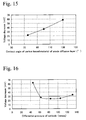
- Fig. 15 is a graph showing a relationship of contact angle of the carbon-based material with water in the anode diffusion layer and voltage decrease.
- the contact angle of the carbon-based material of the cathode diffusion layer is less than 130°, flooding phenomenon occurs by the generated water in the cathode, reducing gas supplying property, and area of fuel shortage under fuel shortage conditions is enlarged.
- the contact angle of the carbon-based material of the anode diffusion layer is more than 90°, water absorbed in the anode diffusion layer is migrated to the anode catalytic layer, flooding phenomenon occurs in the anode catalytic layer, reducing gas supplying property, and area of fuel shortage under fuel shortage conditions is enlarged.
- differential pressure of the cathode and anode measured by the differential pressure method must be in a range of 60 to 120 mmaq.
- Fig. 16 is a graph showing a relationship of the differential pressure of the cathode diffusion layer and voltage decrease
- Fig. 17 is a graph showing a relationship of the differential pressure of the anode diffusion layer and voltage decrease.
- the differential pressures of the anode diffusion layer and the cathode diffusion layer are closely associated with each other; for example, even if the water absorption ratio of anode diffusion layer at 60°C is in an appropriate range, gas diffusion water amount cannot be efficiently controlled in the case in which the differential pressure of the cathode diffusion layer is not in an appropriate range.
- the degree of appropriate adhesion property is expressed by a measured value by the cyclic voltammetric method.
- Fig. 10 is a graph showing a relationship of adhesion ratio and voltage decrease. As is clear from Fig. 10, if the adhesion ratio is not less than 15%, voltage decrease is not more than 30 mV, and desirable voltage efficiency is exhibited. Therefore, in the present invention, it is necessary that the ratio of quantity of electric charge of catalytic material of the cathode catalytic layer existing in proton conductive passage from the polymer electrolyte membrane measured by a cyclic voltammetric method be not less than 15% to the quantity of electric charge of all the catalytic material existing in the cathode catalytic layer.
- the electrode assembly for polymer electrolyte fuel cell of the present invention is further explained by way of Examples and Comparative Examples.
- the water holding layer includes carbon-based material and 5 to 20 wt% of water holding material to the total amount of electron conductive material and the water holding material.
- ion conductive polymer (trade name: Nafion SE20192, produced by Du Pont), 10 g of platinum supporting carbon particles in which the weight ratio of carbon black to platinum is 50:50 (trade name: TEC10E50E, produced by Tanaka Kikinzoku Kogyo K. K.), and 2.5 g of crystalline carbon fiber (trade name: VGCF, produced by Showa Denko) were mixed to prepare cathode catalytic paste.
- This cathode catalytic paste was coated on a FEP sheet so that the Pt amount is 0.3 mg/cm 2 , and was dried to prepare a cathode electrode sheet.
- ion conductive polymer (trade name: Nafion SE20192, produced by Du Pont), 4.5 g of carbon black (trade name: Vulcan XC75, produced by Cabot), 2.5 g of crystalline carbon fiber (trade name: VGCF, produced by Showa Denko), and 0.5 g of ZSM5 (produced by Tosoh Corporation) were mixed to prepare a foundation paste A1.
- 12 g of Teflon (trademark) powder (trade name: L170J, produced by Asahi Glass Co., Ltd.) and 18 g of carbon black powder (trade name: Vulcan XC75, produced by Cabot) were mixed with ethylene glycol to prepare a foundation paste B1.
- the foundation paste B1 was coated on a carbon paper (trade name: TGP060, produced by Toray Industries Inc.) which was beforehand process to be water-repellant so as to be 2.3 mg/cm 2 , the foundation paste A1 was coated so as to be 0.3 mg/cm 2 , and dried, to prepare an anode diffusion layer.
- the foundation paste B1 was coated on the same carbon paper so as to be 2.3 mg/cm 2 , and was dried to obtain a cathode diffusion layer.
- the electrode sheets of the anode and cathode are transferred to an electrolyte membrane by a decal method (unifying pressure of 40 kg/cm 2 ) to prepare membrane electrode assembly CCM.
- the anode diffusion layer and the cathode diffusion layer mentioned above, were layered on both sides of the CCM to form electrode assembly MEA of Example 1.
- a membrane electrode assembly MEA of Example 2 was prepared in a manner similar to that of Example 1.
- the foundation paste A2 was prepared by mixing 25 g of ion conductive polymer (trade name: Nafion SE20192, produced by Du Pont), 4.0 g of carbon black powder (trade name: Vulcan XC75, produced by Cabot), 2.5 g of crystalline carbon fiber (trade name: VGCF, produced by Showa Denko), and 1 g of ZSM5 (produced by Tosoh Corporation).
- a membrane electrode assembly MEA of Example 3 was prepared in a manner similar to that of Example 1. It should be noted that the foundation paste A3 was prepared by mixing 25 g of ion conductive polymer (trade name: Nafion SE20192, produced by Du Pont), 4.75 g of carbon black powder (trade name: Vulcan XC75, produced by Cabot), 2.5 g of crystalline carbon fiber (trade name: VGCF, produced by Showa Denko), and 0.25 g of ZSM5 (produced by Tosoh Corporation).
- ion conductive polymer trade name: Nafion SE20192, produced by Du Pont
- carbon black powder trade name: Vulcan XC75, produced by Cabot
- VGCF crystalline carbon fiber
- ZSM5 produced by Tosoh Corporation
- a membrane electrode assembly MEA of Example 4 was prepared in a manner similar to that of Example 1. It should be noted that the foundation paste A4 was prepared by mixing 25 g of ion conductive polymer (trade name: Nafion SE20192, produced by Du Pont), 4.5 g of carbon black powder (trade name: Vulcan XC75, produced by Cabot), and 0.5 g of ZSM5 (produced by Tosoh Corporation).
- ion conductive polymer trade name: Nafion SE20192, produced by Du Pont
- carbon black powder trade name: Vulcan XC75, produced by Cabot
- ZSM5 produced by Tosoh Corporation
- Example 5 Except that an anode diffusion layer in which a foundation paste B2 was coated on a carbon paper (trade name: TP060, produced by Toray Industries Inc.) beforehand treated to be water-repellent and dried so as to be 2.3 mg/cm 2 , was used instead of the anode diffusion layer of Example 1, a membrane electrode assembly MEA of Example 5 was prepared in a manner similar to that of Example 1.
- a carbon paper trade name: TP060, produced by Toray Industries Inc.
- the foundation paste B2 was prepared by mixing 12 g of Teflon (trademark) powder (trade name: L170J, produced by Asahi Glass Co., Ltd.), 16.2 g of carbon black powder (trade name: Vulcan XC75, produced by Cabot), and 1.8 g of ZSM5 (produced by Tosoh Corporation) with ethylene glycol.
- Teflon (trademark) powder trade name: L170J, produced by Asahi Glass Co., Ltd.
- carbon black powder trade name: Vulcan XC75, produced by Cabot
- ZSM5 produced by Tosoh Corporation
- a membrane electrode assembly MEA of Comparative Example 1 was prepared in a manner similar to that of Example 1.
- the foundation paste A5 was prepared by mixing 25 g of ion conductive polymer (trade name: Nafion SE20192, produced by Du Pont), 3.75 g of carbon black powder (trade name: Vulcan XC75, produced by Cabot), 2.5 g of crystalline carbon fiber (trade name: VGCF, produced by Showa Denko), and 1.25 g of ZSM5 (produced by Tosoh Corporation).
- a membrane electrode assembly MEA of Comparative Example 2 was prepared in a manner similar to that of Example 1. It should be noted that the foundation paste A6 was prepared by mixing 30 g of ion conductive polymer (trade name: Nafion SE20192, produced by Du Pont), 4.5 g of carbon black powder (trade name: Vulcan XC75, produced by Cabot), and 0.5 g of ZSM5 (produced by Tosoh Corporation).
- ion conductive polymer trade name: Nafion SE20192, produced by Du Pont
- carbon black powder trade name: Vulcan XC75, produced by Cabot
- ZSM5 produced by Tosoh Corporation
- a membrane electrode assembly MEA of Comparative Example 3 was prepared in a manner similar to that of Example 1. It should be noted that the foundation paste A7 was prepared by mixing 35 g of ion conductive polymer (trade name: Nafion SE20192, produced by Du Pont), 4.5 g of carbon black powder (trade name: Vulcan XC75, produced by Cabot), and 0.5 g of ZSM5 (produced by Tosoh Corporation).
- ion conductive polymer trade name: Nafion SE20192, produced by Du Pont
- carbon black powder trade name: Vulcan XC75, produced by Cabot
- ZSM5 produced by Tosoh Corporation
- a membrane electrode assembly MEA of Comparative Example 4 was prepared in a manner similar to that of Example 1. It should be noted that the foundation paste A8 was prepared by mixing 25 g of ion conductive polymer (trade name: Nafion SE20192, produced by Du Pont), 5 g of carbon black powder (trade name: Vulcan XC75, produced by Cabot), and 2.5 g of crystalline carbon fiber (trade name: VGCF, produced by Showa Denko).
- ion conductive polymer trade name: Nafion SE20192, produced by Du Pont
- carbon black powder trade name: Vulcan XC75, produced by Cabot
- VGCF crystalline carbon fiber
- a membrane electrode assembly MEA of Comparative Example 5 was prepared in a manner similar to that of Example 1. It should be noted that the foundation paste A9 was prepared by mixing 25 g of ion conductive polymer (trade name: Nafion SE20192, produced by Du Pont), 4.5 g of carbon black powder (trade name: Vulcan XC75, produced by Cabot), 1.5 g of crystalline carbon fiber (trade name: VGCF, produced by Showa Denko), and 0.5 g of ZSM5 (produced by Tosoh Corporation).
- ion conductive polymer trade name: Nafion SE20192
- carbon black powder trade name: Vulcan XC75, produced by Cabot
- VGCF crystalline carbon fiber
- ZSM5 produced by Tosoh Corporation
- a membrane electrode assembly MEA of Comparative Example 6 was prepared in a manner similar to that of Example 1. It should be noted that the foundation paste A10 was prepared by mixing 25 g of ion conductive polymer (trade name: Nafion SE20192, produced by Du Pont), 4.5 g of carbon black powder (trade name: Vulcan XC75, produced by Cabot), 3.5 g of crystalline carbon fiber (trade name: VGCF, produced by Showa Denko), and 0.5 g of ZSM5 (produced by Tosoh Corporation).
- ion conductive polymer trade name: Nafion SE20192
- carbon black powder trade name: Vulcan XC75, produced by Cabot
- VGCF crystalline carbon fiber
- ZSM5 produced by Tosoh Corporation
- a membrane electrode assembly MEA of Comparative Example 7 was prepared in a manner similar to that of Example 1.
- a fuel shortage test was performed on fuel cells containing membrane electrode assemblies of Examples and Comparative Examples mentioned above.
- the test conditions were as follows: cell temperature: 80°C, humidity amount: 45 RH% in the anode and 85 RH% in the cathode, utilization ratio at 0.5 A/cm 2 : 100% in the anode and 60% in the cathode.
- Current density of the test was changed from 0 to 1 A/cm 2 over time as shown in Fig. 18, and this change was repeated 500 times.
- a difference of voltage calculated by terminal voltages before and after the fuel test is shown in Table 1.
- a membrane electrode assembly MEA of Example 6 was prepared in a manner similar to that of Example 1. It should be noted that the foundation paste A11 was prepared by mixing 25 g of ion conductive polymer (trade name: Nafion SE20192, produced by Du Pont), 5 g of carbon black powder (trade name: Ketjen black, produced by Cabot), and 2.5 g of crystalline carbon fiber (trade name: VGCF, produced by Showa Denko).
- ion conductive polymer trade name: Nafion SE20192, produced by Du Pont
- carbon black powder trade name: Ketjen black, produced by Cabot
- VGCF crystalline carbon fiber
- a membrane electrode assembly MEA of Example 7 was prepared in a manner similar to that of Example 1. It should be noted that the foundation paste A12 was prepared by mixing 25 g of ion conductive polymer (trade name: Nafion SE20192, produced by Du Pont), and 5 g of carbon black powder (trade name: Ketjen black, produced by Cabot).
- Example 8 Except that an anode diffusion layer in which a foundation paste A13 was coated on a carbon paper (trade name: TP060, produced by Toray Industries Inc.) treated beforehand to be water-repellent and dried so as to be 2.3 mg/cm 2 , is used instead of the anode diffusion layer of Example 1, a membrane electrode assembly MEA of Example 8 was prepared in a manner similar to that of Example 1. It should be noted that the foundation paste A13 was prepared by mixing 12 g of Teflon (trademark) dispersion (trade name: L170J, produced by Asahi Glass Co., Ltd.), and 18 g of carbon black powder (trade name: Ketjen black, produced by Cabot).
- a membrane electrode assembly MEA of Comparative Example 9 was prepared in a manner similar to that of Example 1. It should be noted that the foundation paste A14 was prepared by mixing 25 g of ion conductive polymer (trade name: Nafion SE20192, produced by Du Pont), 5 g of carbon black powder (trade name: AB-5, produced by Cabot), and 2.5 g of crystalline carbon fiber (trade name: VGCF, produced by Showa Denko).
- ion conductive polymer trade name: Nafion SE20192, produced by Du Pont
- carbon black powder trade name: AB-5, produced by Cabot
- VGCF crystalline carbon fiber
- a membrane electrode assembly MEA of Comparative Example 10 was prepared in a manner similar to that of Example 1. It should be noted that the foundation paste A15 was prepared by mixing 25 g of ion conductive polymer (trade name: Nafion SE20192, produced by Du Pont), 5 g of carbon black powder (trade name: Vulcan XC75, produced by Denka), and 2.5 g of crystalline carbon fiber (trade name: VGCF, produced by Showa Denko).
- ion conductive polymer trade name: Nafion SE20192, produced by Du Pont
- carbon black powder trade name: Vulcan XC75, produced by Denka
- VGCF crystalline carbon fiber
- a membrane electrode assembly MEA of Comparative Example 11 was prepared in a manner similar to that of Example 1. It should be noted that the foundation paste A16 was prepared by mixing 18 g of ion conductive polymer (trade name: Nafion SE20192, produced by Du Pont), 5 g of carbon black powder (trade name: Ketjen black, produced by Cabot), and 3.5 g of crystalline carbon fiber (trade name: VGCF, produced by Showa Denko).
- ion conductive polymer trade name: Nafion SE20192, produced by Du Pont
- carbon black powder trade name: Ketjen black, produced by Cabot
- VGCF crystalline carbon fiber
- a membrane electrode assembly MEA of Comparative Example 12 was prepared in a manner similar to that of Example 1. It should be noted that the foundation paste A17 was prepared by mixing 25 g of ion conductive polymer (trade name: Nafion SE20192, produced by Du Pont), 5 g of carbon black powder (trade name: Ketjen black, produced by Cabot), and 3.5 g of crystalline carbon fiber (trade name: VGCF, produced by Showa Denko).
- ion conductive polymer trade name: Nafion SE20192, produced by Du Pont
- carbon black powder trade name: Ketjen black, produced by Cabot
- VGCF crystalline carbon fiber
- a membrane electrode assembly MEA of Comparative Example 13 was prepared in a manner similar to that of Example 1. It should be noted that the foundation paste A18 was prepared by mixing 30 g of ion conductive polymer (trade name: Nafion SE20192, produced by Du Pont), 5 g of carbon black powder (trade name: Ketjen black, produced by Cabot), and 1 g of crystalline carbon fiber (trade name: VGCF, produced by Showa Denko).
- ion conductive polymer trade name: Nafion SE20192, produced by Du Pont
- carbon black powder trade name: Ketjen black, produced by Cabot
- VGCF crystalline carbon fiber
- a membrane electrode assembly MEA of Comparative Example 14 was prepared in a manner similar to that of Example 6.
- a membrane electrode assembly MEA of Comparative Example 15 was prepared in a manner similar to that of Example 6.
- a fuel shortage test was performed about fuel cells containing membrane electrode assemblies of Examples and Comparative Examples mentioned above.
- the test conditions were the same as the test of the first embodiment described above.
- a difference of voltage calculated by terminal voltages before and after the fuel test is shown in Table 2.
- ion conductive polymer (trade name: Nafion SE20192, produced by Du Pont), 10 g of platinum supporting carbon particles in which weight ratio of carbon black and platinum is 50:50 (trade name: TEC10E50E, produced by Tanaka Kikinzoku Kogyo K. K.), and 2.5 g of crystalline carbon fiber (trade name: VGCF, produced by Showa Denko) were mixed to prepare cathode catalytic paste.
- This cathode catalytic paste was coated to a FEP sheet so that Pt amount is 0.3 mg/cm 2 , and dried to prepare a cathode electrode sheet.
- a carbon paper (trade name: TGP060, produced by Toray Industries Inc.) was immersed into water at 95°C in a pressure resistant container for 100 hours to perform hydrophilic treatment so that contact angle with water is 75°.
- ion conductive polymer (trade name: Nafion SE20192, produced by Du Pont) and 5 g of carbon black powder (trade name: Ketjen black, produced by Cabot) were mixed to prepare a foundation paste C1.
- 12 g of Teflon (trademark) powder (trade name: L170J, produced by Asahi Glass Co., Ltd.) and 18 g of carbon black powder (trade name: Vulcan XC75, produced by Cabot) were mixed with ethylene glycol to prepare a foundation paste D1.
- the foundation paste C1 was coated on the carbon paper treated to be hydrophilic as described above so as to be 1.0 mg/cm 2 , and dried to prepare an anode diffusion layer.
- the foundation paste D 1 was coated on the same carbon paper so as to be 2.3 mg/cm 2 , and dried to obtain a cathode diffusion layer.
- the electrode sheets of the anode and cathode are transferred to an electrolyte membrane by a decal method (unifying pressure of 40 kg/cm 2 ) to prepare membrane electrode assembly CCM.
- the anode diffusion layer and the cathode diffusion layer mentioned above, were layered on both sides of the CCM to form electrode assembly MEA of Example 9.
- membrane electrode assembly MEA of Example 10 was prepared in a manner similar to that of Example 9.
- a membrane electrode assembly MEA of Example 11 was prepared in a manner similar to that of Example 9. It should be noted that the foundation paste C2 was prepared by mixing 12 g of Teflon (trademark) powder (trade name: L170J, produced by Asahi Glass Co., Ltd.) and 18 g of carbon black powder (trade name: Ketjen black, produced by Cabot) with ethylene glycol.
- Teflon (trademark) powder trade name: L170J, produced by Asahi Glass Co., Ltd.
- carbon black powder trade name: Ketjen black, produced by Cabot
- a membrane electrode assembly MEA of Example 12 was prepared in a manner similar to that of Example 9. It should be noted that the foundation paste C3 was prepared by mixing 18 g of Teflon (trademark) powder (trade name: L170J, produced by Asahi Glass Co., Ltd.) and 12 g of carbon black powder (trade name: Ketjen black, produced by Cabot) with ethylene glycol.
- Teflon (trademark) powder trade name: L170J, produced by Asahi Glass Co., Ltd.
- carbon black powder trade name: Ketjen black, produced by Cabot
- a membrane electrode assembly MEA of Comparative Example 16 was prepared in a manner similar to that of Example 9.
- a membrane electrode assembly MEA of Comparative Example 17 was prepared in a manner similar to that of Example 9.
- a membrane electrode assembly MEA of Comparative Example 18 was prepared in a manner similar to that of Example 9.
- a membrane electrode assembly MEA of Comparative Example 19 was prepared in a manner similar to that of Example 9. It should be noted that the foundation paste C4 was prepared by mixing 25 g of ion conductive polymer (trade name: Nafion SE20192, produced by Du Pont) and 5 g of carbon black powder (trade name: AB-5, produced by Cabot).
- a membrane electrode assembly MEA of Comparative Example 20 was prepared in a manner similar to that of Example 9. It should be noted that the foundation paste C5 was prepared by mixing 25 g of ion conductive polymer (trade name: Nafion SE20192, produced by Du Pont) and 5 g of carbon black powder (trade name: Vulcan XC75, produced by Cabot).
- a membrane electrode assembly MEA of Comparative Example 21 was prepared in a manner similar to that of Example 9. It should be noted that the foundation paste C6 was prepared by mixing 40 g of ion conductive polymer (trade name: Nafion SE20192, produced by Du Pont) and 5 g of carbon black powder (trade name: Ketjen black, produced by Cabot).
- a membrane electrode assembly MEA of Comparative Example 22 was prepared in a manner similar to that of Example 9. It should be noted that the foundation paste C7 was prepared by mixing 15 g of ion conductive polymer (trade name: Nafion SE20192, produced by DuPont) and 5 g of carbon black powder (trade name: Ketjen black, produced by Cabot).
- a membrane electrode assembly MEA of Comparative Example 23 was prepared in a manner similar to that of Example 9. It should be noted that the foundation paste C8 was prepared by mixing 35 g of ion conductive polymer (trade name: Nafion SE20192, produced by Du Pont) and 5 g of carbon black powder (trade name: Ketjen black, produced by Cabot).
- a membrane electrode assembly MEA of Comparative Example 24 was prepared in a manner similar to that of Example 9. It should be noted that the foundation paste C9 was prepared by mixing 20 g of ion conductive polymer (trade name: Nafion SE20192, produced by Du Pont) and 5 g of carbon black powder (trade name: Ketjen black, produced by Cabot).
- a membrane electrode assembly MEA of Comparative Example 26 was prepared in a manner similar to that of Example 9.
- the electrode assemblies of Examples 9 to 12 in which contact angle of carbon-based material, water absorption amount of carbon particles, water absorption ratio of the anode diffusion layer, differential pressure, and adhesion ratio are within the range of the present invention, have penetration resistance of not more than 5 m ⁇ and difference of voltage at the fuel shortage test of not more than 30 mV. Efficiencies were not decreased very much.
- ion conductive polymer (trade name: Nafion SE20192, produced by Du Pont), 10 g of platinum supporting carbon particles in which weight ratio of carbon black and platinum is 50:50 (trade name: TEC10E50E, produced by Tanaka Kikinzoku Kogyo K. K.), and 2.5 g of crystalline carbon fiber (trade name: VGCF, produced by Showa Denko) were mixed to prepare a cathode catalytic paste.
- This cathode catalytic paste was coated on a FEP sheet so that Pt amount is 0.3 mg/cm 2 , and dried to prepare a cathode electrode sheet.
- two sheets of carbon paper (trade name: TGP060, produced by Toray Industries Inc.) were immersed in water at 95°C in a pressure resistant container to perform hydrophilic treatment so that contact angle with water thereof become 140° and 75°, to prepare two sheets of carbon paper for a cathode diffusion layer and an anode diffusion layer mutually.
- Teflon (trademark) powder (trade name: L170J, produced by Asahi Glass Co., Ltd.) and 18 g of carbon black powder (trade name: Ketjen black, produced by Cabot) were mixed with ethylene glycol to prepare a foundation paste E1
- 12 g of Teflon (trademark) powder (trade name: L170J, produced by Asahi Glass Co., Ltd.) and 18 g of carbon black powder (trade name: AB-5, produced by Cabot) were mixed with ethylene glycol to prepare a foundation paste F1.
- the foundation paste E1 was coated to the carbon paper for anode diffusion layer treated to be hydrophilic as described above so as to be 2.3 mg/cm 2 , and dried to obtain the anode diffusion layer.
- the foundation paste F1 was coated on the carbon paper for cathode diffusion layer so as to be 2.3 mg/cm 2 , and dried to obtain the cathode diffusion layer.
- the electrode sheets of the anode and cathode are transferred to an electrolyte membrane by a decal method (unifying pressure of 40 kg/cm 2 ) to prepare membrane electrode assembly CCM.
- the anode diffusion layer and the cathode diffusion layer mentioned above, were layered on both sides of the CCM to form electrode assembly MEA of Example 13.
- a membrane electrode assembly MEA of Example 14 was prepared in a manner similar to that of Example 13. It should be noted that the foundation paste F2 was prepared by mixing 12 g of Teflon (trademark) powder (trade name: L170J, produced by Asahi Glass Co., Ltd.) and 18 g of carbon black powder (trade name: VulcanXC75, produced by Cabot) with ethylene glycol.
- Teflon (trademark) powder trade name: L170J, produced by Asahi Glass Co., Ltd.
- carbon black powder trade name: VulcanXC75, produced by Cabot
- a membrane electrode assembly MEA of Example 15 was prepared in a manner similar to that of Example 13.
- the foundation paste E2 was prepared by mixing 9 g of Teflon (trademark) powder (trade name: L170J, produced by Asahi Glass Co., Ltd.) and 21 g of carbon black powder (trade name: Ketjen black, produced by Cabot) with ethylene glycol
- the foundation paste F3 was prepared by mixing 9 g of Teflon (trademark) powder (trade name: L170J, produced by Asahi Glass Co., Ltd.) and 21 g of carbon black powder (trade name: AB-5, produced by Cabot) with ethylene glycol.
- a membrane electrode assembly MEA of Example 16 was prepared in a manner similar to that of Example 13.
- the foundation paste E3 was prepared by mixing 21 g of Teflon (trademark) powder (trade name: L170J, produced by Asahi Glass Co., Ltd.) and 9 g of carbon black powder (trade name: Ketjen black, produced by Cabot) with ethylene glycol
- the foundation paste F4 was prepared by mixing 21 g of Teflon (trademark) powder (trade name: L170J, produced by Asahi Glass Co., Ltd.) and 9 g of carbon black powder (trade name: AB-5, produced by Cabot) with ethylene glycol.
- a membrane electrode assembly MEA of Comparative Example 27 was prepared in a manner similar to that of Example 13. It should be noted that the foundation paste F5 was prepared by mixing 12 g of Teflon (trademark) powder (trade name: L170J, produced by Asahi Glass Co., Ltd.) and 18 g of carbon black powder (trade name: Ketjen black, produced by Cabot) with ethylene glycol.
- Teflon (trademark) powder trade name: L170J, produced by Asahi Glass Co., Ltd.
- carbon black powder trade name: Ketjen black, produced by Cabot
- a membrane electrode assembly MEA of Comparative Example 28 was prepared in a manner similar to that of Example 13. It should be noted that the foundation paste F6 was prepared by mixing 12 g of Teflon (trademark) powder (trade name: L170J, produced by Asahi Glass Co., Ltd.) and 18 g of carbon black powder (trade name: Ketjen black 600JD, produced by Cabot) with ethylene glycol.
- Teflon (trademark) powder trade name: L170J, produced by Asahi Glass Co., Ltd.
- carbon black powder trade name: Ketjen black 600JD, produced by Cabot
- a membrane electrode assembly MEA of Comparative Example 29 was prepared in a manner similar to that of Example 13. It should be noted that the foundation paste E4 was prepared by mixing 12 g of Teflon (trademark) powder (trade name: L170J, produced by Asahi Glass Co., Ltd.) and 18 g of carbon black powder (trade name: AB-5, produced by Cabot) with ethylene glycol.
- Teflon (trademark) powder trade name: L170J, produced by Asahi Glass Co., Ltd.
- carbon black powder trade name: AB-5, produced by Cabot
- a membrane electrode assembly MEA of Comparative Example 30 was prepared in a manner similar to that of Example 13. It should be noted that the foundation paste E5 was prepared by mixing 12 g of Teflon (trademark) powder (trade name: L170J, produced by Asahi Glass Co., Ltd.) and 18 g of carbon black powder (trade name: Vulcan XC75, produced by Cabot) with ethylene glycol.
- Teflon (trademark) powder trade name: L170J, produced by Asahi Glass Co., Ltd.
- carbon black powder trade name: Vulcan XC75, produced by Cabot
- a membrane electrode assembly MEA of Comparative Example 31 was prepared in a manner similar to that of Example 13. It should be noted that the foundation paste E6 was prepared by mixing 24 g of Teflon (trademark) powder (trade name: L170J, produced by Asahi Glass Co., Ltd.) and 6 g of carbon black powder (trade name: Ketjen black, produced by Cabot) with ethylene glycol.
- Teflon (trademark) powder trade name: L170J, produced by Asahi Glass Co., Ltd.
- carbon black powder trade name: Ketjen black, produced by Cabot
- a membrane electrode assembly MEA of Comparative Example 32 was prepared in a manner similar to that of Example 13. It should be noted that the foundation paste E7 was prepared by mixing 6 g of Teflon (trademark) powder (trade name: L170J, produced by Asahi Glass Co., Ltd.) and 24 g of carbon black powder (trade name: Ketjen black, produced by Cabot) with ethylene glycol.
- Teflon (trademark) powder trade name: L170J, produced by Asahi Glass Co., Ltd.
- carbon black powder trade name: Ketjen black, produced by Cabot
- a membrane electrode assembly MEA of Comparative Example 33 was prepared in a manner similar to that of Example 13. It should be noted that the foundation paste F7 was prepared by mixing 24 g of Teflon (trademark) powder (trade name: L170J, produced by Asahi Glass Co., Ltd.) and 6 g of carbon black powder (trade name: AB-5, produced by Cabot) with ethylene glycol.
- Teflon (trademark) powder trade name: L170J, produced by Asahi Glass Co., Ltd.
- carbon black powder trade name: AB-5, produced by Cabot
- a membrane electrode assembly MEA of Comparative Example 34 was prepared in a manner similar to that of Example 13. It should be noted that the foundation paste F8 was prepared by mixing 6 g of Teflon (trademark) powder (trade name: L170J, produced by Asahi Glass Co., Ltd.) and 24 g of carbon black powder (trade name: AB-5, produced by Cabot) with ethylene glycol.
- Teflon (trademark) powder trade name: L170J, produced by Asahi Glass Co., Ltd.
- carbon black powder trade name: AB-5, produced by Cabot
- a membrane electrode assembly MEA of Comparative Example 35 was prepared in a manner similar to that of Example 13.
- a membrane electrode assembly MEA of Comparative Example 36 was prepared in a manner similar to that of Example 13.
- Fuel shortage tests were performed on fuel cells containing membrane electrode assemblies of Examples and Comparative Examples mentioned above.
- the test conditions were the same as the test of the first embodiment described above. Differences in voltage calculated by terminal voltages before and after the fuel test are shown in Table 4.
- Electrodes of Samples 1 to 4 were prepared in a manner similar to that of Example 13 except for using carbon-based materials each having different contact angle with water, and fuel shortage tests similar to those described above was performed. The results are shown in Table 5.
- the reverse diffusion water amount from the cathode to the anode can be increased, and water holding property is given to the anode diffusion layer, not to the anode catalytic layer. Therefore, water is supplied from the anode diffusion layer to the anode catalytic layer under conditions of fuel shortage, and the water is electrolyzed in the anode catalytic layer to supply protons to the polymer electrolyte membrane. Efficiency deterioration can be restrained even under fuel shortage conditions.
Landscapes
- Chemical & Material Sciences (AREA)
- General Chemical & Material Sciences (AREA)
- Electrochemistry (AREA)
- Chemical Kinetics & Catalysis (AREA)
- Engineering & Computer Science (AREA)
- Sustainable Development (AREA)
- Sustainable Energy (AREA)
- Life Sciences & Earth Sciences (AREA)
- Manufacturing & Machinery (AREA)
- Composite Materials (AREA)
- Materials Engineering (AREA)
- Inert Electrodes (AREA)
- Fuel Cell (AREA)
Abstract
A water holding layer having a carbon-based material and a water
holding material is arranged on an anode diffusion layer. The water
holding material is contained at 5 to 20 wt% of total weight of the water
holding material and an electron conductive material. Alternatively,
carbon particles having water absorption amount at saturated water vapor
pressure at 60°C is not less than 150 cc/g are contained in the anode
diffusion layer. Water absorption ratio of the anode diffusion layer at
60°C is in a range of 40 to 85%, a differential pressure is in a range of 60 to
120 mmaq, and a ratio of quantity of electric charge of catalytic material of
the cathode catalytic layer existing in proton conductive passage from the
polymer electrolyte membrane is not less than 15% of the quantity of
electric charge of all the catalytic material existing in the cathode catalytic
layer. Furthermore, a layer including carbon particles having water
absorption amount at saturated water vapor pressure at 60°C of not less
than 150 cc/g and fluorine resin, is arranged on a carbon-based material
having a contact angle with water of not more than 90° by performing a
hydrophilic treatment. The water absorption ratio at 60°C is in a range of
40 to 85 wt%, and the penetration resistance is not more than 5mΩ.
Description
The present invention relates to a membrane electrode assembly for
polymer electrolyte fuel cells, and in particular, relates to a membrane
electrode assembly for polymer electrolyte fuel cell in which efficiency
deterioration when there is a shortage of fuel is reduced.
A unit of a polymer electrolyte fuel cell is formed by laminating
separators at both sides of a tabular membrane electrode assembly (MEA),
and then plural units are laminated to form a fuel cell stack. The
membrane electrode assembly is a layered structure in which a polymer
electrolyte membrane is arranged between a pair of gas diffusion electrodes
forming a cathode and an anode. The gas diffusion electrode is a structure
in which a gas diffusion layer is formed on an outer surface of an electrode
catalytic layer contacting the electrolyte membrane. In such a fuel cell,
hydrogen gas supplied through a gas passage of the separator facing on the
gas diffusion electrode of the anode and oxidizing gas supplied through a
gas passage of the separator facing on the gas diffusion electrode of the
cathode electrochemically react and thereby generate electricity.
In an operation of the fuel cell, the gas diffusion layer conducts
electrons generated by the electric chemical reaction between the electrode
catalytic layer and the separator, and at the same time, diffuses fuel gas and
oxidizing gas. Protons (H+) and electrons are generated from the fuel gas
in the anode electrode catalytic layer, water is generated from oxygen,
protons, and electrons in the cathode electrode catalytic layer, and protons
are ion conducted through the electrolyte membrane. As a result, electric
power can be obtained between the electrode catalytic layers of cathode
and anode.
During driving of vehicles or the like, power output sometimes
varies greatly. Therefore, in the case in which the above-mentioned
polymer electrolyte fuel cell is used as a power source, fuel gas cannot be
supplied sufficiently to meet the required amount of fuel gas. In this case,
fuel gas runs short temporarily in the membrane electrode assembly.
During the circumstance of fuel shortage, current is maintained by using
protons supplied from the electrolysis of water shown in following formula
(1).
2H2O → 4H+ + 4e-+O2 (1)
Furthermore, in the case in which the fuel shortage continues more
in the circumstances promoting the electrolysis of water, the following
corrosion reaction of carbon (2) may occur.
2H2O + C → 4H+ + 4e-+ CO2 (2)
In the reaction (2), carbon black which is a support body of the
catalyst is corroded, and power generation efficiency of the membrane
electrode assembly is deteriorated.
To solve such a problem, a technique in which corrosion resistance
of carbon is improved by increasing supported ratio of catalyst or by using
carbon having higher corrosion resistance is disclosed in Patent Application
Publication No. 01/15254). Furthermore, from the viewpoint of the above
reaction of formula (1), a technique in which catalyst promoting
electrolysis of water is added to the anode catalytic layer (Patent
Application Publications No. 01/15247 and No. 01/15255), a technique in
which material to increase water amount is added to the anode catalytic
layer or diffusion layer (Patent Application Publications No. 01/15255 and
No. 01/15249) or the like are disclosed.
The conventional techniques mentioned above are effective in a
temporary fuel shortage; however, in the case in which fuel shortage occurs
repeatedly in practical operations or in the case of a rated operation, there is
a problem of the flooding phenomenon. Flooding is a phenomenon in
which micropores of gas diffusion flow passage in the anode catalytic layer
are filled with water, and therefore gas diffusion is inhibited. The
flooding inhibits supply of fuel gas, enlarges the area of fuel shortage in the
anode (fuel gas electrode), and promotes corrosion reaction of carbon, and
as a result, deteriorates efficiency of the membrane electrode assembly.
The present invention was completed in view of the
above-mentioned circumstances. An object of the present invention is to
provide a membrane electrode assembly for polymer electrolyte fuel cell in
which efficiency deterioration at shortage of fuel is restrained.
In the membrane electrode assembly for polymer electrolyte fuel
cell of the present invention having a polymer electrolyte membrane, a
cathode and an anode both having catalytic layers and diffusion layers, the
anode diffusion layer has characteristics (1) to (3) below.
In the present invention, the anode catalytic layer does not have a
water holding property; however, the water holding layer in which water
holding material is contained at 5 to 20 wt% to the total amount of the
electron conductive material and the water holding material, is arranged on
the carbon-based material, or alternatively, carbon particles having water
absorption amount at saturated water vapor pressure at 60°C is not less than
150 cc/g, are contained. Therefore, water absorption ratio of the anode
diffusion layer at 60°C is in a range of 40 to 85%, and the anode diffusion
layer has high water holding property. In the case in which fuel runs short,
water is supplied from the anode diffusion layer to the anode catalytic layer,
the water is electrolyzed in the anode catalytic layer, protons are supplied to
the polymer electrolyte membrane.
In this way, in the membrane electrode assembly for polymer
electrolyte fuel cell of the present invention, since the water is supplied to
the anode catalytic layer only at shortage of fuel, flooding does not occur in
the anode catalytic layer, and on the other hand, since water is electrolyzed
in the anode catalytic layer during the shortage of fuel, corrosion reaction
of carbon which is a next step of electrolysis of water can be restrained.
In a membrane electrode assembly for polymer electrolyte fuel cell
of another preferred embodiment of the present invention, having a
polymer electrolyte membrane, and an anode and a cathode both having
catalytic layers and diffusion layers, the anode diffusion layer has
characteristics (1) to (4) below.
In this embodiment, the anode catalytic layer does not have a water
holding property; however, a carbon-based material of the anode diffusion
layer is processed to be hydrophilic, and that carbon particles having water
absorption amount at saturated water vapor pressure at 60°C of not less
than 150 cc/g, are contained. Therefore, water absorption ratio of the
anode diffusion layer at 60°C is in a range of 40 to 85%, and the anode
diffusion layer has high water holding property. In the case in which fuel
runs short, water is supplied from the anode diffusion layer to the anode
catalytic layer, the water is electrolyzed in the anode catalytic layer, and
protons are supplied to the polymer electrolyte membrane.
Furthermore, in a membrane electrode assembly for polymer
electrolyte fuel cell of another desirable embodiment of the present
invention, having a polymer electrolyte membrane, and an anode and a
cathode both having catalytic layers and diffusion layers:
In this embodiment, carbon particles having water absorption
amount at saturated water vapor pressure at 60°C of not less than 150 cc/g,
are contained in the anode diffusion layer, carbon particles having water
absorption amount at saturated water vapor pressure at 60°C of not more
than 150 cc/g, are contained in the cathode diffusion layer, and water
absorption ratio of the anode diffusion layer at 60°C is in a range of 40 to
85%. Therefore, amount of water of reverse diffusion from the cathode to
the anode is increased, and water holding property of the anode diffusion
layer is high. In the case in which fuel runs short, water is supplied from
the anode diffusion layer to the anode catalytic layer, the water is
electrolyzed in the anode catalytic layer, protons are supplied to the
polymer electrolyte membrane.
Furthermore, in a membrane electrode assembly for polymer
electrolyte fuel cell of another desirable embodiment of the present
invention, carbon-based material of the anode diffusion layer is processed
to be hydrophilic and to have a contact angle with water of not more than
90°, and carbon-based material of the cathode diffusion layer is processed
to be hydrophobic and to have a contact angle with water of not less than
130°. In this embodiment, the anode diffusion layer can have high water
holding property, reverse diffusion of generated water and supplied water
from the cathode to the anode can be performed efficiently, electrolysis of
water in the anode catalytic layer can be promoted, and corrosion reaction
of carbon can be restrained more.
In the membrane electrode assembly for polymer electrolyte fuel
cell of the present invention, since constituent elements except for the
cathode catalytic layer, cathode diffusion layer, and anode diffusion layer
are not limited in particular, these constituent elements are explained
below.
The anode diffusion layer of membrane electrode assembly for
polymer electrolyte fuel cell of the first and second embodiments of the
present invention, can be consist of (1) carbon-based material, (2) a layer
containing carbon particles and fluorine resin arranged thereon, and (3) a
layer containing carbon particles, polymer electrolyte, void forming agent,
and water holding material further arranged thereon. Alternatively, it can
be consist of (1) carbon-based material and (2) a layer containing carbon
particles, fluorine resin, and water holding material arranged thereon.
Furthermore, the anode diffusion layer of the present invention is
required to have water absorption ratio at 60°C in a range of 40 to 85% by
arranging water holding layer containing 5 to 20 wt% of water holding
material which increases water holding property to the total amount of
electron conductive material and water holding material, on the
carbon-based material, or by containing carbon particles having water
absorption amount at saturated water vapor pressure at 60°C of not less
than 150 cc/g. Fig. 1 is a graph showing a relationship of content ratio of
the water holding material to the total amount of electron conductive
material and water holding material, and voltage decrease. Fig. 2 is a
graph showing a relationship of water absorption amount of carbon
particles and voltage decrease. As is clear from these figures, if the
content ratio of the water holding material is in a range of 5 to 20 wt%, or
if the water absorption amount of the carbon particles is not less than 150
cc/g, voltage decrease is not more than 30 mV, and desirable voltage
efficiency is exhibited. Fig. 3 is a graph showing a relationship of water
absorption ratio of the anode diffusion layer at 60°C and voltage decrease.
As is clear from Fig. 3, if the water absorption ratio of the anode diffusion
layer is in a range of 40 to 85%, voltage decrease is not more than 30 mV,
and desirable voltage efficiency is exhibited. On the other hand, if the
content amount of the water holding material or water absorption amount
of the carbon particles are below the range mentioned above, water
absorption ratio of the anode diffusion layer is too low, and the
above-mentioned effect cannot be obtained. If the content amount of the
water holding material or water absorption amount of the carbon particles
are above the range mentioned above, water absorption ratio of the anode
diffusion layer is too high, gas supplying property is deteriorated by
flooding phenomenon, and fuel shortage area is increased. As the water
holding material of the present invention, oxides such as zeolite, γ-alumina,
or silica can be used.
In the present invention, differential pressure measured by a
differential pressure measuring method must be in a range of 60 to 120
mmaq. Fig. 4 is a graph showing a relationship of differential pressure of
the anode diffusion layer and voltage decrease. As is clear from Fig. 4, if
the differential pressure of the anode diffusion layer is in a range of 60 to
120 mmaq, voltage decrease is not more than 30 mV, and desirable voltage
efficiency is exhibited. On the other hand, if the differential pressure is
above 120 mmaq, gas supplying property is deteriorated, and fuel shortage
area is increased. If the differential pressure is below 60 mmaq, supplying
protons only by electrolysis of water is not sufficient since the water
exhausting property is high, and corrosion reaction of carbon material in
the anode is promoted. The differential pressure measuring method
mentioned herein is a method in which anode diffusion layer is set and held
at mid-stream of a gas flow passage, a pre-determined flow amount of
reaction gas is flowed, pressures in front of and behind the anode diffusion
layer are measured, and the difference in the pressures is calculated.
Furthermore, if adhesion of the polymer electrolyte membrane and
the anode catalytic layer is not sufficient, protons generated by electrolysis
of water cannot be supplied to the polymer electrolyte membrane
appropriately. Therefore, in the present invention, appropriate degree of
adhesion is expressed by a measured value of the cyclic voltammetric
method. That is, adhesion ratio in the present invention is defined by the
following formula.
Adhesion ratio (%) = (Measured value by cyclic voltammetric method
under condition of one side humidified) / (Measured value by cyclic
voltammetric method under condition of both side humidified) x 100
The cyclic voltammetric method under conditions of both sides humidified
as mentioned herein is a method in which humidified gas is supplied to
both anode and cathode to humidify the entire electrode assembly and the
amount of electric charge of all the catalytic material of all of the electrode
catalytic layer depending on electrochemical surface area is measured.
On the other hand, the cyclic voltammetric method under conditions of one side humidified as mentioned herein is a method in which humidified gas is supplied only from the anode, the water supplied from the anode is dispersed only to conductive passages of the polymer membrane of the cathode side, and the amount of electric charge of the catalytic material of the cathode catalytic layer existing from the polymer electrolyte membrane to proton conductive passages depending on electrochemical surface area is measured. If the amount of the catalytic material of the cathode catalytic layer existing from the polymer electrolyte membrane to proton conductive passages becomes larger, the adhesion ratio becomes larger and the catalytic material is effectively used.
On the other hand, the cyclic voltammetric method under conditions of one side humidified as mentioned herein is a method in which humidified gas is supplied only from the anode, the water supplied from the anode is dispersed only to conductive passages of the polymer membrane of the cathode side, and the amount of electric charge of the catalytic material of the cathode catalytic layer existing from the polymer electrolyte membrane to proton conductive passages depending on electrochemical surface area is measured. If the amount of the catalytic material of the cathode catalytic layer existing from the polymer electrolyte membrane to proton conductive passages becomes larger, the adhesion ratio becomes larger and the catalytic material is effectively used.
Fig. 5 is a graph showing a relationship of adhesion ratio and
voltage decrease. As is clear from Fig. 5, if the adhesion ratio is not less
than 15%, voltage decrease is not more than 30 mV, and desirable voltage
efficiency is exhibited. Therefore, in the present invention, it is necessary
that the ratio of quantity of electric charge of catalytic material of the
cathode catalytic layer existing in proton conductive passage from the
polymer electrolyte membrane measured by the cyclic voltammetric
method be not less than 15% of the quantity of electric charge of all of the
catalytic material existing in the cathode catalytic layer.
In the electrode assembly of the present invention, it is desirable
that a resistance overvoltage loss at 1 A/cm2 be less than 10 mV. Fig. 6 is
a graph showing the relationship of penetration resistance and voltage loss
at 1 A/cm2. As is clear from Fig. 6, if the penetration resistance is not
more than 5 mΩ, the voltage loss at 1 A/cm2 is less than 10 mV, and
desirable voltage efficiency is exhibited.
Furthermore, carbon-based material of the anode diffusion layer in
third embodiment is limited to the carbon material which is processed to be
hydrophilic and not more than 90° of contact angle with water. It is
necessary to prepare water absorption ratio of the anode diffusion layer at
60°C in a range of 40 to 85% by arranging a layer having fluorine resin and
carbon particles whose water absorption amount at saturated water vapor
pressure at 60°C is not less than 150 cc/g, on this carbon-based material.
Fig.7 is a graph showing a relationship of contact angle of the carbon-based
material with water and voltage decrease. As is clear from Figs. 7 and 2,
if the contact angle of carbon-based material with water is not more than
90° and if the water absorption amount of the carbon particles is not less
than 150 cc/g, voltage decrease is not more than 30 mV, desirable voltage
efficiency is exhibited. Fig. 8 is a graph showing a relationship of water
absorption ratio of the anode diffusion layer at 60°C and the voltage
decrease. Also in this embodiment, as is clear from Fig. 8, if the water
absorption ratio of the anode diffusion layer is in a range of 40 to 85%,
voltage decrease is not more than 30 mV, desirable voltage efficiency is
exhibited. However, if the contact angle of the carbon-based material is
above the range, water absorbed in the anode diffusion layer goes to the
anode catalytic layer, flooding phenomenon occurs in the anode catalytic
layer, gas supplying property is deteriorated, and area of fuel shortage
under fuel shortage conditions is enlarged. If the water absorption amount
of the carbon particles is below the range, the effect of the present
invention cannot be obtained since the water absorption ratio is too low.
On the other hand, the water absorption amount of the carbon particles is above the range, gas supplying property is deteriorated by the flooding phenomenon and area of fuel shortage under fuel shortage conditions is enlarged since the water absorption ratio of the anode diffusion layer is too high.
On the other hand, the water absorption amount of the carbon particles is above the range, gas supplying property is deteriorated by the flooding phenomenon and area of fuel shortage under fuel shortage conditions is enlarged since the water absorption ratio of the anode diffusion layer is too high.
Also, in this embodiment, according to the same reason mentioned
above, it is necessary that the differential pressure measured by the
differential pressure measuring method be in a range from 60 to 120 mmaq.
Fig. 9 is a graph showing a relationship of the differential pressure of the
anode diffusion layer and the voltage decrease.
Fig. 10 is a graph showing a relationship of adhesion ratio and the
voltage decrease in this embodiment. As is clear from Fig. 10, if the
adhesion ratio is not less than 15%, the voltage decrease is not more than
30 mV, desirable voltage efficiency is exhibited. Therefore, in the present
invention, it is necessary that the ratio of the quantity of electric charge of
catalytic material of the cathode catalytic layer existing in proton
conductive passage from the polymer electrolyte membrane measured by a
cyclic voltammetric method be not less than 15% to the quantity of electric
charge of all the catalytic material existing in the cathode catalytic layer.
In an electrode assembly for the polymer electrolyte fuel cell of the
forth embodiment of the present invention, void forming agent is added to
the cathode catalytic layer to prevent flooding in the cathode catalytic layer,
and water-repellant carbon particles are used in the cathode diffusion layer
to supply water which is generated in the cathode or supplied from outside,
to the anode side smoothly by reverse diffusion. It is necessary that this
water repellant carbon particle have water absorption amount at saturated
water vapor pressure at 60°C of less than 150 cc/g. Fig. 11 is a graph
showing a relationship of water absorption amount of the carbon particles
in the cathode diffusion layer of this embodiment and voltage decrease.
As is clear from Fig. 11, if the water absorption amount of the carbon
particles in the cathode diffusion layer is less than 150 cc/g, voltage
decrease is not more than 30 mV, desirable voltage efficiency is exhibited.
Since hydrophilic carbon particles are used in the anode diffusion
layer of this embodiment, water can be retained. In the case in which fuel
is in short supply, the retained water is supplied to the anode catalytic layer
to promote electrolysis of water, generated protons are supplied to
electrolyte membrane, and reverse diffusion water from the cathode side
can also be used in the electrolysis of water in the anode catalytic layer.
In this way, corrosion of carbon which is a next step of the electrolysis of
water is difficult to occur. It is necessary that the hydrophilic carbon
particle have water absorption amount at saturated water vapor pressure at
60°C of not less than 150 cc/g. Fig. 12 is a graph showing a relationship
of water absorption amount of carbon particles in the anode diffusion layer
of this embodiment and voltage decrease. As is clear from Fig. 12, if the
water absorption amount of the carbon particles in the anode diffusion layer
is not less than 150 cc/g, voltage decrease is not more than 30 mV,
desirable voltage efficiency is exhibited. Furthermore, it is necessary that
the anode diffusion layer having high water holding property by adding the
hydrophilic carbon particles have water absorption ratio at 60°C in a range
of 40 to 85%. Fig. 13 is a graph showing a relationship of water
absorption ratio of the anode diffusion layer of this embodiment at 60°C
and voltage decrease. As is clear from Fig. 13, also in this embodiment, if
the water absorption ratio of the anode diffusion layer is in a range of 40 to
85%, voltage decrease is not more than 30 mV, desirable voltage efficiency
is exhibited.
It is desirable that the carbon-based material of the cathode
diffusion layer of this embodiment be processed to be water-repellent and
to have a contact angle with water of not less than 130°, and it is desirable
that the carbon-based material of the anode diffusion layer be processed to
have a contact angle with water of not more than 90°. In this way, balance
of water holding property of the cathode and anode can be controlled, that
is, not only can water be contained in the anode diffusion layer but also
generated water in the cathode migrate to the anode to utilize the reverse
diffusion water efficiently. In this way, electrolysis of water in the anode
catalytic layer can be promoted more efficiently, to improve restraining
effect of carbon corrosion reaction. Fig. 14 is a graph showing a
relationship of contact angle of the carbon-based material with water in the
cathode diffusion layer and voltage decrease, and Fig. 15 is a graph
showing a relationship of contact angle of the carbon-based material with
water in the anode diffusion layer and voltage decrease. As is clear from
these Figs. 14 and 15, if the contact angle of the carbon-based material of
the cathode diffusion layer is not less than 130° or if the contact angle of
the carbon-based material of the anode diffusion layer is not more than 90°,
voltage decrease is not more than 30 mV, and desirable voltage efficiency is
exhibited. However, if the contact angle of the carbon-based material of
the cathode diffusion layer is less than 130°, flooding phenomenon occurs
by the generated water in the cathode, reducing gas supplying property, and
area of fuel shortage under fuel shortage conditions is enlarged. On the
other hand, if the contact angle of the carbon-based material of the anode
diffusion layer is more than 90°, water absorbed in the anode diffusion
layer is migrated to the anode catalytic layer, flooding phenomenon occurs
in the anode catalytic layer, reducing gas supplying property, and area of
fuel shortage under fuel shortage conditions is enlarged.
Also in this embodiment, differential pressure of the cathode and
anode measured by the differential pressure method must be in a range of
60 to 120 mmaq. Fig. 16 is a graph showing a relationship of the
differential pressure of the cathode diffusion layer and voltage decrease,
and Fig. 17 is a graph showing a relationship of the differential pressure of
the anode diffusion layer and voltage decrease. As is clear from Figs. 16
and 17, if the differential pressure of the cathode diffusion layer and the
anode diffusion layer is in a range of 60 to 120 mmaq, voltage decrease is
not more than 30 mV, and desirable voltage efficiency is exhibited. The
differential pressures of the anode diffusion layer and the cathode diffusion
layer are closely associated with each other; for example, even if the water
absorption ratio of anode diffusion layer at 60°C is in an appropriate range,
gas diffusion water amount cannot be efficiently controlled in the case in
which the differential pressure of the cathode diffusion layer is not in an
appropriate range.
Furthermore, if adhesion property of the polymer electrolyte
membrane and the cathode catalytic layer is not sufficient, the
above-mentioned reverse diffusion water cannot be supplied appropriately,
and if adhesion property of the polymer electrolyte membrane and the
anode catalytic layer is not sufficient, protons generated by electrolysis of
water cannot be supplied to the polymer electrolyte membrane
appropriately. Therefore, in the present invention, the degree of
appropriate adhesion property is expressed by a measured value by the
cyclic voltammetric method.
Fig. 10 is a graph showing a relationship of adhesion ratio and
voltage decrease. As is clear from Fig. 10, if the adhesion ratio is not less
than 15%, voltage decrease is not more than 30 mV, and desirable voltage
efficiency is exhibited. Therefore, in the present invention, it is necessary
that the ratio of quantity of electric charge of catalytic material of the
cathode catalytic layer existing in proton conductive passage from the
polymer electrolyte membrane measured by a cyclic voltammetric method
be not less than 15% to the quantity of electric charge of all the catalytic
material existing in the cathode catalytic layer.
The electrode assembly for polymer electrolyte fuel cell of the
present invention is further explained by way of Examples and
Comparative Examples.
First, an embodiment in which a water holding layer is arranged on
the anode diffusion layer, is explained. The water holding layer includes
carbon-based material and 5 to 20 wt% of water holding material to the
total amount of electron conductive material and the water holding
material.
35 g of ion conductive polymer (trade name: Nafion SE20192,
produced by Du Pont), 10 g of platinum supporting carbon particles in
which the weight ratio of carbon black to platinum is 50:50 (trade name:
TEC10E50E, produced by Tanaka Kikinzoku Kogyo K. K.), and 2.5 g of
crystalline carbon fiber (trade name: VGCF, produced by Showa Denko)
were mixed to prepare cathode catalytic paste. This cathode catalytic
paste was coated on a FEP sheet so that the Pt amount is 0.3 mg/cm2, and
was dried to prepare a cathode electrode sheet. On the other hand, 36.8 g
of ion conductive polymer (trade name: Nafion SE20192, produced by Du
Pont) and 10 g of Pt-Ru supporting carbon particles in which weight ratio
of the carbon black and the catalyst is 46:54 (trade name: TEC61E54,
Pt:Ru=1:1, Tanaka Kikinzoku Kogyo K. K.) were mixed to prepare an
anode catalytic paste. This anode catalytic paste was coated to a FEP
sheet so that catalyst amount is 0.15 mg/cm2, and dried to prepare an anode
electrode sheet.
25 g of ion conductive polymer (trade name: Nafion SE20192,
produced by Du Pont), 4.5 g of carbon black (trade name: Vulcan XC75,
produced by Cabot), 2.5 g of crystalline carbon fiber (trade name: VGCF,
produced by Showa Denko), and 0.5 g of ZSM5 (produced by Tosoh
Corporation) were mixed to prepare a foundation paste A1. 12 g of Teflon
(trademark) powder (trade name: L170J, produced by Asahi Glass Co.,
Ltd.) and 18 g of carbon black powder (trade name: Vulcan XC75,
produced by Cabot) were mixed with ethylene glycol to prepare a
foundation paste B1. Next, the foundation paste B1 was coated on a
carbon paper (trade name: TGP060, produced by Toray Industries Inc.)
which was beforehand process to be water-repellant so as to be 2.3 mg/cm2,
the foundation paste A1 was coated so as to be 0.3 mg/cm2, and dried, to
prepare an anode diffusion layer. On the other hand, only the foundation
paste B1 was coated on the same carbon paper so as to be 2.3 mg/cm2, and
was dried to obtain a cathode diffusion layer.
The electrode sheets of the anode and cathode are transferred to an
electrolyte membrane by a decal method (unifying pressure of 40 kg/cm2)
to prepare membrane electrode assembly CCM. The anode diffusion
layer and the cathode diffusion layer mentioned above, were layered on
both sides of the CCM to form electrode assembly MEA of Example 1.
Except that a foundation paste A2 was used instead of the
foundation paste A1, a membrane electrode assembly MEA of Example 2
was prepared in a manner similar to that of Example 1. It should be noted
that the foundation paste A2 was prepared by mixing 25 g of ion
conductive polymer (trade name: Nafion SE20192, produced by Du Pont),
4.0 g of carbon black powder (trade name: Vulcan XC75, produced by
Cabot), 2.5 g of crystalline carbon fiber (trade name: VGCF, produced by
Showa Denko), and 1 g of ZSM5 (produced by Tosoh Corporation).
Except that a foundation paste A3 was used instead of the
foundation paste A1, a membrane electrode assembly MEA of Example 3
was prepared in a manner similar to that of Example 1. It should be noted
that the foundation paste A3 was prepared by mixing 25 g of ion
conductive polymer (trade name: Nafion SE20192, produced by Du Pont),
4.75 g of carbon black powder (trade name: Vulcan XC75, produced by
Cabot), 2.5 g of crystalline carbon fiber (trade name: VGCF, produced by
Showa Denko), and 0.25 g of ZSM5 (produced by Tosoh Corporation).
Except that a foundation paste A4 was used instead of the
foundation paste A1, a membrane electrode assembly MEA of Example 4
was prepared in a manner similar to that of Example 1. It should be noted
that the foundation paste A4 was prepared by mixing 25 g of ion
conductive polymer (trade name: Nafion SE20192, produced by Du Pont),
4.5 g of carbon black powder (trade name: Vulcan XC75, produced by
Cabot), and 0.5 g of ZSM5 (produced by Tosoh Corporation).
Except that an anode diffusion layer in which a foundation paste B2
was coated on a carbon paper (trade name: TP060, produced by Toray
Industries Inc.) beforehand treated to be water-repellent and dried so as to
be 2.3 mg/cm2, was used instead of the anode diffusion layer of Example 1,
a membrane electrode assembly MEA of Example 5 was prepared in a
manner similar to that of Example 1. It should be noted that the
foundation paste B2 was prepared by mixing 12 g of Teflon (trademark)
powder (trade name: L170J, produced by Asahi Glass Co., Ltd.), 16.2 g of
carbon black powder (trade name: Vulcan XC75, produced by Cabot), and
1.8 g of ZSM5 (produced by Tosoh Corporation) with ethylene glycol.
Except that a foundation paste A5 was used instead of the
foundation paste A1, a membrane electrode assembly MEA of Comparative
Example 1 was prepared in a manner similar to that of Example 1. It
should be noted that the foundation paste A5 was prepared by mixing 25 g
of ion conductive polymer (trade name: Nafion SE20192, produced by Du
Pont), 3.75 g of carbon black powder (trade name: Vulcan XC75, produced
by Cabot), 2.5 g of crystalline carbon fiber (trade name: VGCF, produced
by Showa Denko), and 1.25 g of ZSM5 (produced by Tosoh Corporation).
Except that a foundation paste A6 was used instead of the
foundation paste A1, a membrane electrode assembly MEA of Comparative
Example 2 was prepared in a manner similar to that of Example 1. It
should be noted that the foundation paste A6 was prepared by mixing 30 g
of ion conductive polymer (trade name: Nafion SE20192, produced by Du
Pont), 4.5 g of carbon black powder (trade name: Vulcan XC75, produced
by Cabot), and 0.5 g of ZSM5 (produced by Tosoh Corporation).
Except that a foundation paste A7 was used instead of the
foundation paste A1, a membrane electrode assembly MEA of Comparative
Example 3 was prepared in a manner similar to that of Example 1. It
should be noted that the foundation paste A7 was prepared by mixing 35 g
of ion conductive polymer (trade name: Nafion SE20192, produced by Du
Pont), 4.5 g of carbon black powder (trade name: Vulcan XC75, produced
by Cabot), and 0.5 g of ZSM5 (produced by Tosoh Corporation).
Except that a foundation paste A8 was used instead of the
foundation paste A1, a membrane electrode assembly MEA of Comparative
Example 4 was prepared in a manner similar to that of Example 1. It
should be noted that the foundation paste A8 was prepared by mixing 25 g
of ion conductive polymer (trade name: Nafion SE20192, produced by Du
Pont), 5 g of carbon black powder (trade name: Vulcan XC75, produced by
Cabot), and 2.5 g of crystalline carbon fiber (trade name: VGCF, produced
by Showa Denko).
Except that a foundation paste A9 was used instead of the
foundation paste A1, a membrane electrode assembly MEA of Comparative
Example 5 was prepared in a manner similar to that of Example 1. It
should be noted that the foundation paste A9 was prepared by mixing 25 g
of ion conductive polymer (trade name: Nafion SE20192, produced by Du
Pont), 4.5 g of carbon black powder (trade name: Vulcan XC75, produced
by Cabot), 1.5 g of crystalline carbon fiber (trade name: VGCF, produced
by Showa Denko), and 0.5 g of ZSM5 (produced by Tosoh Corporation).
Except that a foundation paste A10 was used instead of the
foundation paste A1, a membrane electrode assembly MEA of Comparative
Example 6 was prepared in a manner similar to that of Example 1. It
should be noted that the foundation paste A10 was prepared by mixing 25 g
of ion conductive polymer (trade name: Nafion SE20192, produced by Du
Pont), 4.5 g of carbon black powder (trade name: Vulcan XC75, produced
by Cabot), 3.5 g of crystalline carbon fiber (trade name: VGCF, produced
by Showa Denko), and 0.5 g of ZSM5 (produced by Tosoh Corporation).
Except that the unifying pressure of the decal method in the
production of the membrane electrode assembly CCM was 30 kg/cm2, a
membrane electrode assembly MEA of Comparative Example 7 was
prepared in a manner similar to that of Example 1.
Except that the unifying pressure of the decal method in the
production of the membrane electrode assembly CCM was 10 kg/cm2, a
membrane electrode assembly of Comparative Example 8 was prepared in
a manner similar to that of Example 1.
A fuel shortage test was performed on fuel cells containing
membrane electrode assemblies of Examples and Comparative Examples
mentioned above. The test conditions were as follows: cell temperature:
80°C, humidity amount: 45 RH% in the anode and 85 RH% in the cathode,
utilization ratio at 0.5 A/cm2: 100% in the anode and 60% in the cathode.
Current density of the test was changed from 0 to 1 A/cm2 over time as
shown in Fig. 18, and this change was repeated 500 times. A difference of
voltage calculated by terminal voltages before and after the fuel test is
shown in Table 1.

The electrode assemblies of Examples 1 to 5 in which content ratio
of the water holding material, water absorption ratio of the anode diffusion
layer, differential pressure, and adhesion ratio are within the range of the
present invention, have penetration resistance of not more than 5 mΩ and
difference of voltage at the fuel shortage test of not more than 30 mV.
Efficiencies were not reduced very much. On the other hand, the
electrode assembly of Comparative Example 1 having too high content
ratio of water holding material, the electrode assemblies of Comparative
Examples 2 and 3 having too high water absorption ratio of the anode
diffusion layer, the electrode assembly of Comparative Example 4 having
too low content ratio of water holding material, water absorption ratio of
the anode diffusion layer and differential pressure, the electrode assembly
of Comparative Example 5 having too low differential pressure, the
electrode assembly of Comparative Example 6 having too high differential
pressure, and the electrode assemblies of Comparative Examples 7 and 8
having too low adhesion ratio, all have penetration resistance of not more
than 5 mΩ; however, difference of voltage in the fuel shortage test exceeds
more than 30 mV. Efficiencies were reduced very much.
Next, an embodiment in which carbon particles having water
absorption amount at saturated water vapor pressure at 60°C of not less
than 150 cc/g are contained in the anode diffusion layer, is explained.
Except that a foundation paste A11 was used instead of the
foundation paste A1, a membrane electrode assembly MEA of Example 6
was prepared in a manner similar to that of Example 1. It should be noted
that the foundation paste A11 was prepared by mixing 25 g of ion
conductive polymer (trade name: Nafion SE20192, produced by Du Pont),
5 g of carbon black powder (trade name: Ketjen black, produced by Cabot),
and 2.5 g of crystalline carbon fiber (trade name: VGCF, produced by
Showa Denko).
Except that a foundation paste A12 was used instead of the
foundation paste A1, a membrane electrode assembly MEA of Example 7
was prepared in a manner similar to that of Example 1. It should be noted
that the foundation paste A12 was prepared by mixing 25 g of ion
conductive polymer (trade name: Nafion SE20192, produced by Du Pont),
and 5 g of carbon black powder (trade name: Ketjen black, produced by
Cabot).
Except that an anode diffusion layer in which a foundation paste
A13 was coated on a carbon paper (trade name: TP060, produced by Toray
Industries Inc.) treated beforehand to be water-repellent and dried so as to
be 2.3 mg/cm2, is used instead of the anode diffusion layer of Example 1, a
membrane electrode assembly MEA of Example 8 was prepared in a
manner similar to that of Example 1. It should be noted that the
foundation paste A13 was prepared by mixing 12 g of Teflon (trademark)
dispersion (trade name: L170J, produced by Asahi Glass Co., Ltd.), and 18
g of carbon black powder (trade name: Ketjen black, produced by Cabot).
Except that a foundation paste A14 was used instead of the
foundation paste A1, a membrane electrode assembly MEA of Comparative
Example 9 was prepared in a manner similar to that of Example 1. It
should be noted that the foundation paste A14 was prepared by mixing 25 g
of ion conductive polymer (trade name: Nafion SE20192, produced by Du
Pont), 5 g of carbon black powder (trade name: AB-5, produced by Cabot),
and 2.5 g of crystalline carbon fiber (trade name: VGCF, produced by
Showa Denko).
Except that a foundation paste A15 was used instead of the
foundation paste A1, a membrane electrode assembly MEA of Comparative
Example 10 was prepared in a manner similar to that of Example 1. It
should be noted that the foundation paste A15 was prepared by mixing 25 g
of ion conductive polymer (trade name: Nafion SE20192, produced by Du
Pont), 5 g of carbon black powder (trade name: Vulcan XC75, produced by
Denka), and 2.5 g of crystalline carbon fiber (trade name: VGCF, produced
by Showa Denko).
Except that a foundation paste A16 was used instead of the
foundation paste A1, a membrane electrode assembly MEA of Comparative
Example 11 was prepared in a manner similar to that of Example 1. It
should be noted that the foundation paste A16 was prepared by mixing 18 g
of ion conductive polymer (trade name: Nafion SE20192, produced by Du
Pont), 5 g of carbon black powder (trade name: Ketjen black, produced by
Cabot), and 3.5 g of crystalline carbon fiber (trade name: VGCF, produced
by Showa Denko).
Except that a foundation paste A17 was used instead of the
foundation paste A1, a membrane electrode assembly MEA of Comparative
Example 12 was prepared in a manner similar to that of Example 1. It
should be noted that the foundation paste A17 was prepared by mixing 25 g
of ion conductive polymer (trade name: Nafion SE20192, produced by Du
Pont), 5 g of carbon black powder (trade name: Ketjen black, produced by
Cabot), and 3.5 g of crystalline carbon fiber (trade name: VGCF, produced
by Showa Denko).
Except that a foundation paste A18 was used instead of the
foundation paste A1, a membrane electrode assembly MEA of Comparative
Example 13 was prepared in a manner similar to that of Example 1. It
should be noted that the foundation paste A18 was prepared by mixing 30 g
of ion conductive polymer (trade name: Nafion SE20192, produced by Du
Pont), 5 g of carbon black powder (trade name: Ketjen black, produced by
Cabot), and 1 g of crystalline carbon fiber (trade name: VGCF, produced by
Showa Denko).
Except that the unifying pressure of the decal method in the
production of the membrane electrode assembly CCM was 30 kg/cm2, a
membrane electrode assembly MEA of Comparative Example 14 was
prepared in a manner similar to that of Example 6.
Except that the unifying pressure of the decal method in the
production of the membrane electrode assembly CCM was 10 kg/cm2, a
membrane electrode assembly MEA of Comparative Example 15 was
prepared in a manner similar to that of Example 6.
A fuel shortage test was performed about fuel cells containing
membrane electrode assemblies of Examples and Comparative Examples
mentioned above. The test conditions were the same as the test of the first
embodiment described above. A difference of voltage calculated by
terminal voltages before and after the fuel test is shown in Table 2.

The electrode assemblies of Examples 6 to 8 in which water
absorption amount of carbon particles, water absorption ratio of the anode
diffusion layer, differential pressure, and adhesion ratio are within the range
of the present invention, have penetration resistance of not more than 5 mΩ
and difference of voltage at the fuel shortage test of not more than 30 mV.
Efficiencies were not deteriorated so much. On the other hand, the
electrode assembly of Comparative Example 9 having too high water
absorption amount of carbon particles, the electrode assembly of
Comparative Example 10 having too low water absorption amount of
carbon particles and too low water absorption ratio of anode diffusion layer,
the electrode assemblies of Comparative Example 11 having too high water
absorption ratio of the anode diffusion layer, the electrode assembly of
Comparative Example 12 having too low differential pressure, the electrode
assembly of Comparative Example 13 having too high differential pressure,
and the electrode assemblies of Comparative Examples 14 and 15 having
too low adhesion ratio, all have penetration resistance of not more than 5
mΩ; however, difference of voltage at the fuel shortage test exceeds more
than 30 mV. Efficiencies were decreased very much.
35 g of ion conductive polymer (trade name: Nafion SE20192,
produced by Du Pont), 10 g of platinum supporting carbon particles in
which weight ratio of carbon black and platinum is 50:50 (trade name:
TEC10E50E, produced by Tanaka Kikinzoku Kogyo K. K.), and 2.5 g of
crystalline carbon fiber (trade name: VGCF, produced by Showa Denko)
were mixed to prepare cathode catalytic paste. This cathode catalytic
paste was coated to a FEP sheet so that Pt amount is 0.3 mg/cm2, and dried
to prepare a cathode electrode sheet. On the other hand, 36.8 g of ion
conductive polymer (trade name: Nafion SE20192, produced by Du Pont)
and 10 g of Pt-Ru supporting carbon particles in which weight ratio of the
carbon black and the catalyst is 46:54 (trade name: TEC61E54, Pt:Ru=1:1,
Tanaka Kikinzoku Kogyo K. K.) were mixed to prepare an anode catalytic
paste. This anode catalytic paste was coated to a FEP sheet so that
catalyst amount is 0.15 mg/cm2, and dried to prepare an anode electrode
sheet.
On the other hand, a carbon paper (trade name: TGP060, produced
by Toray Industries Inc.) was immersed into water at 95°C in a pressure
resistant container for 100 hours to perform hydrophilic treatment so that
contact angle with water is 75°.
25 g of ion conductive polymer (trade name: Nafion SE20192,
produced by Du Pont) and 5 g of carbon black powder (trade name: Ketjen
black, produced by Cabot) were mixed to prepare a foundation paste C1.
12 g of Teflon (trademark) powder (trade name: L170J, produced by Asahi
Glass Co., Ltd.) and 18 g of carbon black powder (trade name: Vulcan
XC75, produced by Cabot) were mixed with ethylene glycol to prepare a
foundation paste D1. Next, the foundation paste C1 was coated on the
carbon paper treated to be hydrophilic as described above so as to be 1.0
mg/cm2, and dried to prepare an anode diffusion layer. On the other hand,
the foundation paste D 1 was coated on the same carbon paper so as to be
2.3 mg/cm2, and dried to obtain a cathode diffusion layer.
The electrode sheets of the anode and cathode are transferred to an
electrolyte membrane by a decal method (unifying pressure of 40 kg/cm2)
to prepare membrane electrode assembly CCM. The anode diffusion
layer and the cathode diffusion layer mentioned above, were layered on
both sides of the CCM to form electrode assembly MEA of Example 9.
Except that coated amount of the foundation paste C 1 of Example 9
was 0.6 mg/cm2, membrane electrode assembly MEA of Example 10 was
prepared in a manner similar to that of Example 9.
Except that a foundation paste C2 was used instead of the
foundation paste C1, a membrane electrode assembly MEA of Example 11
was prepared in a manner similar to that of Example 9. It should be noted
that the foundation paste C2 was prepared by mixing 12 g of Teflon
(trademark) powder (trade name: L170J, produced by Asahi Glass Co.,
Ltd.) and 18 g of carbon black powder (trade name: Ketjen black, produced
by Cabot) with ethylene glycol.
Except that a foundation paste C3 was used instead of the
foundation paste C1, a membrane electrode assembly MEA of Example 12
was prepared in a manner similar to that of Example 9. It should be noted
that the foundation paste C3 was prepared by mixing 18 g of Teflon
(trademark) powder (trade name: L170J, produced by Asahi Glass Co.,
Ltd.) and 12 g of carbon black powder (trade name: Ketjen black, produced
by Cabot) with ethylene glycol.
Except that the contact angle with water was set to 100° in the
hydrophilic treatment of the carbon paper by controlling time of immersion
into hot water, a membrane electrode assembly MEA of Comparative
Example 16 was prepared in a manner similar to that of Example 9.
Except that the contact angle with water was set to 120° in the
hydrophilic treatment of the carbon paper by controlling time of immersion
into hot water, a membrane electrode assembly MEA of Comparative
Example 17 was prepared in a manner similar to that of Example 9.
Except that the contact angle with water was set to 140° in the
hydrophilic treatment of the carbon paper by controlling time of immersion
into hot water, a membrane electrode assembly MEA of Comparative
Example 18 was prepared in a manner similar to that of Example 9.
Except that a foundation paste C4 was used instead of the
foundation paste C1 and the coated amount was 1.8 mg/cm2 in the anode
diffusion layer forming process, a membrane electrode assembly MEA of
Comparative Example 19 was prepared in a manner similar to that of
Example 9. It should be noted that the foundation paste C4 was prepared
by mixing 25 g of ion conductive polymer (trade name: Nafion SE20192,
produced by Du Pont) and 5 g of carbon black powder (trade name: AB-5,
produced by Cabot).
Except that a foundation paste C5 was used instead of the
foundation paste C1 and the coated amount was 2.3 mg/cm2 in the anode
diffusion layer forming process, a membrane electrode assembly MEA of
Comparative Example 20 was prepared in a manner similar to that of
Example 9. It should be noted that the foundation paste C5 was prepared
by mixing 25 g of ion conductive polymer (trade name: Nafion SE20192,
produced by Du Pont) and 5 g of carbon black powder (trade name: Vulcan
XC75, produced by Cabot).
Except that a foundation paste C6 was used instead of the
foundation paste C1 and the coated amount was 1.8 mg/cm2 in the anode
diffusion layer forming process, a membrane electrode assembly MEA of
Comparative Example 21 was prepared in a manner similar to that of
Example 9. It should be noted that the foundation paste C6 was prepared
by mixing 40 g of ion conductive polymer (trade name: Nafion SE20192,
produced by Du Pont) and 5 g of carbon black powder (trade name: Ketjen
black, produced by Cabot).
Except that a foundation paste C7 was used instead of the
foundation paste C 1 and the coated amount was 0.8 mg/cm2 in the anode
diffusion layer forming process, a membrane electrode assembly MEA of
Comparative Example 22 was prepared in a manner similar to that of
Example 9. It should be noted that the foundation paste C7 was prepared
by mixing 15 g of ion conductive polymer (trade name: Nafion SE20192,
produced by DuPont) and 5 g of carbon black powder (trade name: Ketjen
black, produced by Cabot).
Except that a foundation paste C8 was used instead of the
foundation paste C1 and the coated amount was 1.2 mg/cm2 in the anode
diffusion layer forming process, a membrane electrode assembly MEA of
Comparative Example 23 was prepared in a manner similar to that of
Example 9. It should be noted that the foundation paste C8 was prepared
by mixing 35 g of ion conductive polymer (trade name: Nafion SE20192,
produced by Du Pont) and 5 g of carbon black powder (trade name: Ketjen
black, produced by Cabot).
Except that a foundation paste C9 was used instead of the
foundation paste C1, a membrane electrode assembly MEA of Comparative
Example 24 was prepared in a manner similar to that of Example 9. It
should be noted that the foundation paste C9 was prepared by mixing 20 g
of ion conductive polymer (trade name: Nafion SE20192, produced by Du
Pont) and 5 g of carbon black powder (trade name: Ketjen black, produced
by Cabot).
Except that the unifying pressure of the decal method in the
production of the membrane electrode assembly CCM was 30 kg/cm2, a
membrane electrode assembly MEA of Comparative Example 25 was
prepared in a manner similar to that of Example 9.
Except that the unifying pressure of the decal method in the
production of the membrane electrode assembly CCM was 10 kg/cm2, a
membrane electrode assembly MEA of Comparative Example 26 was
prepared in a manner similar to that of Example 9.
Fuel shortage tests were performed on fuel cells containing
membrane electrode assemblies of Examples and Comparative Examples
mentioned above. The test conditions were the same as the test of the first
embodiment described above. Differences in voltage calculated by
terminal voltages before and after the fuel test are shown in Table 3.

The electrode assemblies of Examples 9 to 12 in which contact
angle of carbon-based material, water absorption amount of carbon
particles, water absorption ratio of the anode diffusion layer, differential
pressure, and adhesion ratio are within the range of the present invention,
have penetration resistance of not more than 5 mΩ and difference of
voltage at the fuel shortage test of not more than 30 mV. Efficiencies
were not decreased very much. On the other hand, the electrode
assemblies of Comparative Examples 16 to 18 having too high contact
angle, the electrode assemblies of Comparative Examples 19 and 20 having
too low water absorption amount of carbon particles, the electrode
assembly of Comparative Example 21 having too high water absorption
ratio of anode diffusion layer, the electrode assembly of Comparative
Example 22 having too low water absorption ratio of anode diffusion layer,
the electrode assembly of Comparative Example 23 having too high
differential pressure, the electrode assembly of Comparative Example 24
having too low differential pressure, and the electrode assemblies of
Comparative Examples 25 and 26 having too low adhesion ratio have
penetration resistance of not more than 5 mΩ; however, difference of
voltages in the fuel shortage test exceed 30 mV. Efficiencies were
decreased very much.
35 g of ion conductive polymer (trade name: Nafion SE20192,
produced by Du Pont), 10 g of platinum supporting carbon particles in
which weight ratio of carbon black and platinum is 50:50 (trade name:
TEC10E50E, produced by Tanaka Kikinzoku Kogyo K. K.), and 2.5 g of
crystalline carbon fiber (trade name: VGCF, produced by Showa Denko)
were mixed to prepare a cathode catalytic paste. This cathode catalytic
paste was coated on a FEP sheet so that Pt amount is 0.3 mg/cm2, and dried
to prepare a cathode electrode sheet. On the other hand, 36.8 g of ion
conductive polymer (trade name: Nafion SE20192, produced by Du Pont)
and 10 g of Pt-Ru supporting carbon particles in which weight ratio of the
carbon black and the catalyst is 46:54 (trade name: TEC61E54, Pt:Ru=1:1,
Tanaka Kikinzoku Kogyo K. K.) were mixed to prepare an anode catalytic
paste. This anode catalytic paste was coated to a FEP sheet so that
catalyst amount is 0.15 mg/cm2, and dried to prepare an anode electrode
sheet.
On the other hand, two sheets of carbon paper (trade name: TGP060,
produced by Toray Industries Inc.) were immersed in water at 95°C in a
pressure resistant container to perform hydrophilic treatment so that contact
angle with water thereof become 140° and 75°, to prepare two sheets of
carbon paper for a cathode diffusion layer and an anode diffusion layer
mutually.
On the other hand, 12 g of Teflon (trademark) powder (trade name:
L170J, produced by Asahi Glass Co., Ltd.) and 18 g of carbon black
powder (trade name: Ketjen black, produced by Cabot) were mixed with
ethylene glycol to prepare a foundation paste E1, and 12 g of Teflon
(trademark) powder (trade name: L170J, produced by Asahi Glass Co.,
Ltd.) and 18 g of carbon black powder (trade name: AB-5, produced by
Cabot) were mixed with ethylene glycol to prepare a foundation paste F1.
Next, the foundation paste E1 was coated to the carbon paper for anode
diffusion layer treated to be hydrophilic as described above so as to be 2.3
mg/cm2, and dried to obtain the anode diffusion layer. On the other hand,
the foundation paste F1 was coated on the carbon paper for cathode
diffusion layer so as to be 2.3 mg/cm2, and dried to obtain the cathode
diffusion layer.
The electrode sheets of the anode and cathode are transferred to an
electrolyte membrane by a decal method (unifying pressure of 40 kg/cm2)
to prepare membrane electrode assembly CCM. The anode diffusion
layer and the cathode diffusion layer mentioned above, were layered on
both sides of the CCM to form electrode assembly MEA of Example 13.
Except that a foundation paste F2 was used instead of the
foundation paste F1, a membrane electrode assembly MEA of Example 14
was prepared in a manner similar to that of Example 13. It should be
noted that the foundation paste F2 was prepared by mixing 12 g of Teflon
(trademark) powder (trade name: L170J, produced by Asahi Glass Co.,
Ltd.) and 18 g of carbon black powder (trade name: VulcanXC75, produced
by Cabot) with ethylene glycol.
Except that foundation pastes E2 and F3 were used instead of the
foundation pastes E1 and F1, a membrane electrode assembly MEA of
Example 15 was prepared in a manner similar to that of Example 13. It
should be noted that the foundation paste E2 was prepared by mixing 9 g of
Teflon (trademark) powder (trade name: L170J, produced by Asahi Glass
Co., Ltd.) and 21 g of carbon black powder (trade name: Ketjen black,
produced by Cabot) with ethylene glycol, and the foundation paste F3 was
prepared by mixing 9 g of Teflon (trademark) powder (trade name: L170J,
produced by Asahi Glass Co., Ltd.) and 21 g of carbon black powder (trade
name: AB-5, produced by Cabot) with ethylene glycol.
Except that foundation pastes E3 and F4 were used instead of the
foundation pastes E1 and F1, a membrane electrode assembly MEA of
Example 16 was prepared in a manner similar to that of Example 13. It
should be noted that the foundation paste E3 was prepared by mixing 21 g
of Teflon (trademark) powder (trade name: L170J, produced by Asahi
Glass Co., Ltd.) and 9 g of carbon black powder (trade name: Ketjen black,
produced by Cabot) with ethylene glycol, and the foundation paste F4 was
prepared by mixing 21 g of Teflon (trademark) powder (trade name: L170J,
produced by Asahi Glass Co., Ltd.) and 9 g of carbon black powder (trade
name: AB-5, produced by Cabot) with ethylene glycol.
Except that foundation paste F5 was used instead of the foundation
paste F1, a membrane electrode assembly MEA of Comparative Example
27 was prepared in a manner similar to that of Example 13. It should be
noted that the foundation paste F5 was prepared by mixing 12 g of Teflon
(trademark) powder (trade name: L170J, produced by Asahi Glass Co.,
Ltd.) and 18 g of carbon black powder (trade name: Ketjen black, produced
by Cabot) with ethylene glycol.
Except that foundation paste F6 was used instead of the foundation
paste F1, a membrane electrode assembly MEA of Comparative Example
28 was prepared in a manner similar to that of Example 13. It should be
noted that the foundation paste F6 was prepared by mixing 12 g of Teflon
(trademark) powder (trade name: L170J, produced by Asahi Glass Co.,
Ltd.) and 18 g of carbon black powder (trade name: Ketjen black 600JD,
produced by Cabot) with ethylene glycol.
Except that foundation paste E4 was used instead of the foundation
paste E1, a membrane electrode assembly MEA of Comparative Example
29 was prepared in a manner similar to that of Example 13. It should be
noted that the foundation paste E4 was prepared by mixing 12 g of Teflon
(trademark) powder (trade name: L170J, produced by Asahi Glass Co.,
Ltd.) and 18 g of carbon black powder (trade name: AB-5, produced by
Cabot) with ethylene glycol.
Except that foundation paste E5 was used instead of the foundation
paste E1, a membrane electrode assembly MEA of Comparative Example
30 was prepared in a manner similar to that of Example 13. It should be
noted that the foundation paste E5 was prepared by mixing 12 g of Teflon
(trademark) powder (trade name: L170J, produced by Asahi Glass Co.,
Ltd.) and 18 g of carbon black powder (trade name: Vulcan XC75,
produced by Cabot) with ethylene glycol.
Except that foundation paste E6 was used instead of the foundation
paste E1, a membrane electrode assembly MEA of Comparative Example
31 was prepared in a manner similar to that of Example 13. It should be
noted that the foundation paste E6 was prepared by mixing 24 g of Teflon
(trademark) powder (trade name: L170J, produced by Asahi Glass Co.,
Ltd.) and 6 g of carbon black powder (trade name: Ketjen black, produced
by Cabot) with ethylene glycol.
Except that foundation paste E7 was used instead of the foundation
paste E1, a membrane electrode assembly MEA of Comparative Example
32 was prepared in a manner similar to that of Example 13. It should be
noted that the foundation paste E7 was prepared by mixing 6 g of Teflon
(trademark) powder (trade name: L170J, produced by Asahi Glass Co.,
Ltd.) and 24 g of carbon black powder (trade name: Ketjen black, produced
by Cabot) with ethylene glycol.
Except that foundation paste F7 was used instead of the foundation
paste E1, a membrane electrode assembly MEA of Comparative Example
33 was prepared in a manner similar to that of Example 13. It should be
noted that the foundation paste F7 was prepared by mixing 24 g of Teflon
(trademark) powder (trade name: L170J, produced by Asahi Glass Co.,
Ltd.) and 6 g of carbon black powder (trade name: AB-5, produced by
Cabot) with ethylene glycol.
Except that foundation paste F8 was used instead of the foundation
paste E1, a membrane electrode assembly MEA of Comparative Example
34 was prepared in a manner similar to that of Example 13. It should be
noted that the foundation paste F8 was prepared by mixing 6 g of Teflon
(trademark) powder (trade name: L170J, produced by Asahi Glass Co.,
Ltd.) and 24 g of carbon black powder (trade name: AB-5, produced by
Cabot) with ethylene glycol.
Except that the unifying pressure of the decal method in the
production of the membrane electrode assembly CCM was 30 kg/cm2, a
membrane electrode assembly MEA of Comparative Example 35 was
prepared in a manner similar to that of Example 13.
Except that the unifying pressure of the decal method in the
production of the membrane electrode assembly CCM was 10 kg/cm2, a
membrane electrode assembly MEA of Comparative Example 36 was
prepared in a manner similar to that of Example 13.
Fuel shortage tests were performed on fuel cells containing
membrane electrode assemblies of Examples and Comparative Examples
mentioned above. The test conditions were the same as the test of the first
embodiment described above. Differences in voltage calculated by
terminal voltages before and after the fuel test are shown in Table 4.

The electrode assemblies of Examples 13 to 16 in which water
absorption amount of carbon particles of the anode diffusion layer and the
cathode diffusion layer, water absorption ratio of the anode diffusion layer,
differential pressure of the anode diffusion layer and the cathode diffusion
layer, and adhesion ratio are within the range of the present invention, have
penetration resistance of not more than 5 mΩ and difference of voltage at
the fuel shortage test of not more than 30 mV. Efficiencies were not
decreased very much. On the other hand, the electrode assemblies of
Comparative Examples 27 and 28 having too high water absorption amount
of carbon particles of the cathode diffusion layer, the electrode assemblies
of Comparative Examples 29 and 30 having too low water absorption
amount of the carbon particles of the anode diffusion layer and too low
water absorption ratio of the anode diffusion layer, the electrode assembly
of Comparative Example 31 having too low water absorption ratio of the
anode diffusion layer and too high differential pressure of the anode
diffusion layer, the electrode assembly of Comparative Example 32 having
too high water absorption ratio of the anode diffusion layer and too low
differential pressure of the anode diffusion layer, the electrode assembly of
Comparative Example 33 having too high differential pressure of the
cathode diffusion layer, the electrode assembly of Comparative Example 34
having too low differential pressure of the cathode diffusion layer, and the
electrode assemblies of Comparative Examples 35 and 36 having too low
adhesion ratio, have penetration resistance of not more than 5 mΩ; however,
differences in voltages in the fuel shortage tests exceed 30 mV.
Efficiencies were decreased very much.
Efficiencies were decreased very much.
To investigate contact angle of the carbon-based material with water
in the anode diffusion layer and the cathode diffusion layer, electrode
assemblies of Samples 1 to 4 were prepared in a manner similar to that of
Example 13 except for using carbon-based materials each having different
contact angle with water, and fuel shortage tests similar to those described
above was performed. The results are shown in Table 5.
Except that the immersion time in hot water in the hydrophilic
treatment of the carbon paper for the anode diffusion layer was controlled
so that the contact angle with water was 100°, a membrane electrode
assembly MEA of Sample 1 was prepared in a manner similar to that of
Example 13.
Except that the immersion time in hot water in the hydrophilic
treatment of the carbon paper for the anode diffusion layer was controlled
so that the contact angle with water was 130°, a membrane electrode
assembly MEA of Sample 2 was prepared in a manner similar to that of
Example 13.
Except that the immersion time in hot water in the hydrophilic
treatment of the carbon paper for the cathode diffusion layer was controlled
so that the contact angle with water was 100°, a membrane electrode
assembly MEA of Sample 3 was prepared in a manner similar to that of
Example 13.
Except that the immersion time in hot water in the hydrophilic
treatment of the carbon paper for the cathode diffusion layer was controlled
so that the contact angle with water was 75°, a membrane electrode
assembly MEA of Sample 4 was prepared in a manner similar to that of
Example 13.

As is clear from Table 5, in Samples 1 and 2 having larger contact
angle of carbon-based material than that of the range of the present
invention (that is, water-repellent), water which must be retained in the
anode diffusion layer migrates to the anode catalytic layer, and flooding
occurred in the anode catalytic layer, and in Samples 3 and 4 having
smaller contact angle of carbon-based material than that of the range of the
present invention (that is, hydrophilic), water generated in the cathode
catalytic layer is retained in the cathode, and flooding occurred in the
cathode catalytic layer, and therefore, in spite the penetration resistance
being not more than 5 mΩ, the voltage difference in the fuel shortage test
undesirably exceeded 30 mV.
As explained above, by the present invention, the reverse diffusion
water amount from the cathode to the anode can be increased, and water
holding property is given to the anode diffusion layer, not to the anode
catalytic layer. Therefore, water is supplied from the anode diffusion
layer to the anode catalytic layer under conditions of fuel shortage, and the
water is electrolyzed in the anode catalytic layer to supply protons to the
polymer electrolyte membrane. Efficiency deterioration can be restrained
even under fuel shortage conditions.
Claims (6)
- A membrane electrode assembly for a polymer electrolyte fuel cell, comprising:wherein water absorption ratio of the anode diffusion layer at 60°C is in a range of 40 to 85%,a polymer electrolyte membrane; andan anode and a cathode each having a catalytic layer and a diffusion layer,the anode diffusion layer further comprising:a carbon-based material; anda water holding layer thereon containing water holding material for 5 to 20 wt% of total weight of an electron conductive material and the water holding material, or carbon particles having water absorption amount at saturated water vapor pressure at 60°C of not less than 150 cc/g,
wherein a differential pressure measured by the differential pressure measuring method is in a range of 60 to 120 mmaq, and
wherein a ratio of quantity of electric charge of catalytic material of the cathode catalytic layer existing in proton conductive passage from the polymer electrolyte membrane measured by a cyclic voltammetric method is not less than 15% of the quantity of electric charge of all the catalytic material existing in the cathode catalytic layer. - The membrane electrode assembly for a polymer electrolyte fuel cell according to claim 1, wherein the anode diffusion layer comprises:a carbon-based material;a layer thereon having carbon particles and fluorine resin; anda layer thereon having carbon particles, a polymer electrolyte, void forming agent, and water holding material.
- The membrane electrode assembly for a polymer electrolyte fuel cell according to claim 1, wherein the anode diffusion layer comprises:a carbon-based material;a layer thereon having carbon particles, fluorine resin, and water holding material.
- A membrane electrode assembly for a polymer electrolyte fuel cell, comprising:wherein water absorption ratio of the anode diffusion layer at 60°C is in a range of 40 to 85%,a polymer electrolyte membrane; andan anode and a cathode each having a catalytic layer and a diffusion layer,the anode diffusion layer further comprising:a carbon-based material having a contact angle with water of not more than 90° by performing a hydrophilic treatment; anda layer thereon having carbon particles having water absorption amount at saturated water vapor pressure at 60°C of not less than 150 cc/g and fluorine resin,
wherein penetration resistance measured by a penetration resistance method is not more than 5 mΩ,
wherein a differential pressure measured by the differential pressure measuring method is in a range of 60 to 120 mmaq, and
wherein a ratio of quantity of electric charge of catalytic material of the cathode catalytic layer existing in proton conductive passage from the polymer electrolyte membrane measured by a cyclic voltammetric method is not less than 15% of the quantity of electric charge of all the catalytic material existing in the cathode catalytic layer. - A membrane electrode assembly for a polymer electrolyte fuel cell, comprising:wherein water absorption amount at saturated water vapor pressure at 60°C of the carbon particles of the anode diffusion layer is not less than 150 cc/g and water absorption amount at saturated water vapor pressure at 60°C of the carbon particles of the cathode diffusion layer is less than 150 cc/g,a polymer electrolyte membrane; andan anode and a cathode each having a catalytic layer and a diffusion layer,the catalytic layer comprising:at least a catalyst;carbon particles supporting the catalyst; andpolymer electrolyte,the cathode catalytic layer further contains void forming agent,the diffusion layer comprising:a carbon-based material; anda layer thereon containing carbon particles and fluorine resin,
wherein water absorption ratio of the anode diffusion layer at 60°C is in a range of 40 to 85%,
wherein a differential pressure of the anode diffusion layer and the cathode diffusion layer measured by the differential pressure measuring method is in a range of 60 to 120 mmaq and penetration resistance measured by a penetration resistance method is not more than 5mΩ, and
wherein a ratio of quantity of electric charge of catalytic material of the cathode catalytic layer existing in proton conductive passage from the polymer electrolyte membrane measured by a cyclic voltammetric method is not less than 15% of the quantity of electric charge of all the catalytic material existing in the cathode catalytic layer. - The membrane electrode assembly for a polymer electrolyte fuel cell according to claim 5, wherein the carbon-based material of the anode diffusion layer has contact angle with water of not more than 90° by performing a hydrophilic treatment, and the carbon-based material of the cathode diffusion layer has a contact angle with water of not less than 130° by performing a water-repellent treatment.
Applications Claiming Priority (7)
| Application Number | Priority Date | Filing Date | Title |
|---|---|---|---|
| JP2002312645A JP4179847B2 (en) | 2002-10-28 | 2002-10-28 | Electrode structure for polymer electrolyte fuel cell |
| JP2002312645 | 2002-10-28 | ||
| JP2003015801 | 2002-10-30 | ||
| JP2002315501A JP4224680B2 (en) | 2002-10-30 | 2002-10-30 | Electrode structure for polymer electrolyte fuel cell |
| JP2002315501 | 2002-10-30 | ||
| JP2002315801A JP4162469B2 (en) | 2002-10-30 | 2002-10-30 | Electrode structure for polymer electrolyte fuel cell |
| PCT/JP2003/013415 WO2004038836A1 (en) | 2002-10-28 | 2003-10-21 | Electrode structure for solid polymer type fuel cell |
Publications (2)
| Publication Number | Publication Date |
|---|---|
| EP1560283A1 true EP1560283A1 (en) | 2005-08-03 |
| EP1560283A4 EP1560283A4 (en) | 2008-06-04 |
Family
ID=32180307
Family Applications (1)
| Application Number | Title | Priority Date | Filing Date |
|---|---|---|---|
| EP03756719A Withdrawn EP1560283A4 (en) | 2002-10-28 | 2003-10-21 | Electrode structure for solid polymer type fuel cell |
Country Status (3)
| Country | Link |
|---|---|
| US (1) | US20060068269A1 (en) |
| EP (1) | EP1560283A4 (en) |
| WO (1) | WO2004038836A1 (en) |
Cited By (2)
| Publication number | Priority date | Publication date | Assignee | Title |
|---|---|---|---|---|
| EP1437784A3 (en) * | 2002-11-08 | 2007-02-28 | HONDA MOTOR CO., Ltd. | Electrode for solid polymer fuel cell |
| EP1780822A3 (en) * | 2005-11-01 | 2007-07-04 | Tomoegawa Co., Ltd. | Gas diffusion electrode, membrane-electrode assembly, polymer electrolyte fuel cell, and methods for producing |
Families Citing this family (2)
| Publication number | Priority date | Publication date | Assignee | Title |
|---|---|---|---|---|
| JP4815460B2 (en) * | 2008-03-13 | 2011-11-16 | 株式会社日立製作所 | Membrane / electrode assembly for fuel cells |
| CN119725560B (en) * | 2023-09-26 | 2026-01-23 | 未势能源科技有限公司 | Anode catalyst layer slurry and preparation method and application thereof |
Family Cites Families (13)
| Publication number | Priority date | Publication date | Assignee | Title |
|---|---|---|---|---|
| JPH0778617A (en) * | 1993-09-09 | 1995-03-20 | Mitsubishi Heavy Ind Ltd | Gas diffusion electrode and manufacture thereof |
| JP3583897B2 (en) * | 1997-04-11 | 2004-11-04 | 三洋電機株式会社 | Fuel cell |
| JPH11214020A (en) * | 1998-01-26 | 1999-08-06 | Japan Science & Technology Corp | Method for maintaining surface of noble metal catalyst clean and fuel cell |
| EP1212805B1 (en) * | 1999-08-23 | 2003-12-17 | Ballard Power Systems Inc. | Fuel cell anode structure for voltage reversal tolerance |
| CA2389740A1 (en) | 1999-08-23 | 2001-03-01 | Ballard Power Systems Inc. | Supported catalysts for the anode of a voltage reversal tolerant fuel cell |
| US6517962B1 (en) * | 1999-08-23 | 2003-02-11 | Ballard Power Systems Inc. | Fuel cell anode structures for voltage reversal tolerance |
| US6280871B1 (en) * | 1999-10-12 | 2001-08-28 | Cabot Corporation | Gas diffusion electrodes containing modified carbon products |
| JP3594533B2 (en) * | 2000-05-30 | 2004-12-02 | 三洋電機株式会社 | Fuel cell |
| JP2002093433A (en) * | 2000-09-12 | 2002-03-29 | Toto Ltd | Solid polymer fuel cell |
| US7022426B2 (en) * | 2000-09-22 | 2006-04-04 | Honda Giken Kogyo Kabushiki Kaisha | Solid polymer fuel cell |
| US20020068213A1 (en) * | 2000-12-01 | 2002-06-06 | Honeywell International, Inc. Law Dept. Ab2 | Multiple layer electrode for improved performance |
| US6821661B2 (en) * | 2001-08-31 | 2004-11-23 | Plug Power, Inc. | Hydrophilic anode gas diffusion layer |
| CA2407202C (en) * | 2001-10-11 | 2009-11-03 | Honda Giken Kogyo Kabushiki Kaisha | Electrode for polymer electrolyte fuel cell |
-
2003
- 2003-10-21 US US10/532,963 patent/US20060068269A1/en not_active Abandoned
- 2003-10-21 EP EP03756719A patent/EP1560283A4/en not_active Withdrawn
- 2003-10-21 WO PCT/JP2003/013415 patent/WO2004038836A1/en not_active Ceased
Cited By (2)
| Publication number | Priority date | Publication date | Assignee | Title |
|---|---|---|---|---|
| EP1437784A3 (en) * | 2002-11-08 | 2007-02-28 | HONDA MOTOR CO., Ltd. | Electrode for solid polymer fuel cell |
| EP1780822A3 (en) * | 2005-11-01 | 2007-07-04 | Tomoegawa Co., Ltd. | Gas diffusion electrode, membrane-electrode assembly, polymer electrolyte fuel cell, and methods for producing |
Also Published As
| Publication number | Publication date |
|---|---|
| WO2004038836A1 (en) | 2004-05-06 |
| US20060068269A1 (en) | 2006-03-30 |
| EP1560283A4 (en) | 2008-06-04 |
Similar Documents
| Publication | Publication Date | Title |
|---|---|---|
| US6847518B2 (en) | Membrane electrode assembly for polymer electrolyte fuel cell | |
| US9337494B2 (en) | Ionic layer with oxygen evolution reaction catalyst for electrode protection | |
| JP5069927B2 (en) | Membrane electrode assembly for fuel cell and method for producing the same | |
| JP2006054165A (en) | Polymer electrolyte fuel cell and method for producing polymer electrolyte fuel cell | |
| EP1489677A2 (en) | Method of making a membrane electrode assembly for electrochemical fuel cells | |
| JP2019040705A (en) | Catalyst layer and electrolyte membrane-electrode assembly for fuel cell, and fuel cell | |
| JP3812901B2 (en) | Electrode structure for polymer electrolyte fuel cell | |
| US20240136540A1 (en) | Method for producing catalyst layers for fuel cells | |
| JP2004186049A (en) | Electrode structure for polymer electrolyte fuel cell and method of manufacturing the same | |
| EP1560283A1 (en) | Electrode structure for solid polymer type fuel cell | |
| JP4162469B2 (en) | Electrode structure for polymer electrolyte fuel cell | |
| JP2006318707A (en) | Electrode structure of polymer electrolyte fuel cell | |
| JP5022707B2 (en) | Solid polymer electrolyte fuel cell | |
| JP4179847B2 (en) | Electrode structure for polymer electrolyte fuel cell | |
| KR102299218B1 (en) | Ionomer-ionomer support composite, method for preparing the same, and catalyst electrode for fuel cell comprising the ionomer-ionomer support composite | |
| JP7359077B2 (en) | Laminate for fuel cells | |
| JP4149244B2 (en) | Electrode structure for polymer electrolyte fuel cell | |
| JP2010073419A (en) | Electrolyte membrane-electrode assembly for fuel cell | |
| JP2007018858A (en) | Fuel cell system | |
| CN101473472B (en) | Fuel cell | |
| JP4224680B2 (en) | Electrode structure for polymer electrolyte fuel cell | |
| EP2157643A1 (en) | Polymer electrolyte fuel cell | |
| EP4435146A2 (en) | Electrode structure and water electrolyzer | |
| US12199291B2 (en) | Electrochemical cell with bilayer electrocatalyst structure | |
| JP7115959B2 (en) | Membrane electrode assembly |
Legal Events
| Date | Code | Title | Description |
|---|---|---|---|
| PUAI | Public reference made under article 153(3) epc to a published international application that has entered the european phase |
Free format text: ORIGINAL CODE: 0009012 |
|
| 17P | Request for examination filed |
Effective date: 20050427 |
|
| AK | Designated contracting states |
Kind code of ref document: A1 Designated state(s): AT BE BG CH CY CZ DE DK EE ES FI FR GB GR HU IE IT LI LU MC NL PT RO SE SI SK TR |
|
| RBV | Designated contracting states (corrected) |
Designated state(s): DE GB |
|
| A4 | Supplementary search report drawn up and despatched |
Effective date: 20080508 |
|
| 17Q | First examination report despatched |
Effective date: 20080813 |
|
| STAA | Information on the status of an ep patent application or granted ep patent |
Free format text: STATUS: THE APPLICATION IS DEEMED TO BE WITHDRAWN |
|
| 18D | Application deemed to be withdrawn |
Effective date: 20110920 |