Technical Field
The present invention relates to a relay device used for connecting
various devices such as clinical examination devices to a network such as a
LAN.
Background Art
Conventionally, systems in which data measured by measuring
devices are collected and processed in a server are used widely. For example,
in hospitals or the like, a system has been introduced in which measuring
devices and testing devices used in individual diagnosis and treatment
departments and testing departments are connected to an intra-hospital
network so that the patient's data can be managed collectively in a server.
However, since the formats of data outputted by individual measuring
and testing devices are not uniform, it is necessary to convert them into a
common format somewhere in the network. FIG. 10 shows an example of a
conventional system configuration. The system shown in FIG. 10 connects
plural kinds of testing devices M1 to Mn to a LAN 82 via a relay 87 and
temporarily sends data measured by the testing devices M1 to Mn from the
relay 87 through the LAN 82 to a communication management terminal 88.
The relay 87 converts the data outputted by a serial bus 84 from the testing
devices M1 to Mn into a format that can be sent through the LAN 82.
Thereafter, the communication management terminal 88 converts the data
received from the relay 87 via the LAN 82 into a common format that can be
processed in a database server 83 etc. and then sends it to the database
server 83.
Conventionally, there is also a known system for processing plural
kinds of measuring devices by a server. For example, a user of the
measuring device registers a format of the result of data processing in a
server in advance. Then, at the time of measuring, the user sends
measurement data and a format ID to the server so that the server converts
the format of the result of processing the measurement data into a format
corresponding to the format ID and outputs this result (JP 2001-338042 A).
However, in the conventional system described above, when
attempting to add a new testing or measuring device, it has been necessary to
set manually an additional communication condition and an additional data
format corresponding to the device to be added. For example, in the case of
the system shown in FIG. 10, information for recognizing a newly-connected
device, a conversion program for converting data measured by this device into
a common format, etc. have to be added to the communication management
terminal 88. Also, in the case of the system described in JP 2001-338042 A,
a data processing format and a format ID for a newly-connected measuring
device need to be added to the server.
Disclosure of Invention
It is an object of the present invention to provide a data relay device
and a data management system that save the above-described time and
trouble and eliminate the need for changing the setting when a new testing
or measuring device is added.
In order to achieve the above-mentioned object, a data relay device of
the present invention is a data relay device for connecting to a network a
plurality of kinds of data generating devices generating data in different
formats, including a data receiving portion for receiving the data from the
plurality of kinds of data generating devices, and a converting portion for
converting the data received by the data receiving portion into a common
format that is processable by other devices on the network.
Further, in order to achieve the above-mentioned object, a data
management system according to the present invention is a data
management system in which, using a data relay device for connecting to a
network a plurality of kinds of data generating devices generating data in
different formats, the data generating devices are connected to a data
management device on the network. The data relay device includes a data
receiving portion for receiving the data from the plurality of kinds of data
generating devices, and a converting portion for converting the data received
by the data receiving portion into a common format that is processable by
other devices on the network. The data management device processes the
data from the data generating devices in the common format.
Brief Description of Drawings
FIG. 1 is a block diagram showing a schematic configuration of a data
management system according to a first embodiment of the present
invention.
FIG. 2 is a drawing for describing an operation of the data
management system according to the first embodiment when a usual testing
is conducted.
FIG. 3 is a drawing for describing an exemplary format of a common
message formed in an adapter in the data management system according to
the first embodiment.
FIG. 4 is a drawing for describing an exemplary format of a common
message for requesting a test result sent from a communication management
terminal to the adapter in the data management system according to the first
embodiment.
FIG. 5 is a drawing for describing an operation of the data
management system according to the first embodiment when a testing device
is added.
FIG. 6 is a drawing for describing an exemplary format of a common
message of connected device information formed by the adapter in the data
management system according to the first embodiment.
FIG. 7 is a block diagram showing a schematic configuration of a data
management system according to a second embodiment of the present
invention.
FIG. 8 is a drawing for describing an operation of the data
management system according to the second embodiment when a testing
device is added.
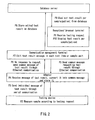
FIG. 9 is a drawing for describing a flow of an analytical processing
conducted by an adapter in the data management system according to the
second embodiment.
FIG. 10 is a block diagram showing an example of a conventional data
management system.
Best Mode for Carrying Out the invention
It is preferable that the above-described data relay device according
to the present invention further includes a connected device information
storing portion for storing device information on the connected data
generating devices, and a device information updating portion for, when
receiving from one of the data generating devices data containing device
information of the data generating device, making a comparison of the device
information in the received data and the device information stored in the
connected device information storing portion and updating a content of the
connected device information storing portion according to a result of the
comparison. Further, it is more preferable to provide a configuration further
including a device information sending portion for sending the device
information received from the data generating device to a data management
device for processing the data from the data generating device via the
network. Incidentally, the device information is information on the data
generating device and can contain any items as long as it contains at least an
item for specifying the kind of this data generating device.
It is preferable that the data relay device further includes a
conversion program storing portion for storing a conversion program for
causing the converting portion to conduct a conversion processing according
to the kind of each of the data generating devices, and a conversion program
obtaining portion for determining whether a conversion program for a data
generating device is stored in the conversion program storing portion when
the data generating device is newly connected and, if not, requesting the
conversion program. Also, it is more preferable to provide a configuration
further including an analyzing portion for extracting a feature of the data
received from the data generating device, thereby specifying the kind of the
connected data generating device.
Also, in the above-described data management system according to
the present invention, it is preferable that the data relay device further
includes a connected device information storing portion for storing device
information on the connected data generating devices, and a device
information updating portion for, when receiving from one of the data
generating devices data containing device information of the data generating
device, making a comparison of the device information in the received data
and the device information stored in the connected device information storing
portion and updating a content of the connected device information storing
portion according to a result of the comparison. Further, it is more
preferable that the data relay device further includes a device information
sending portion for sending the device information received from the data
generating device to the data management device via the network.
Preferably, the data management system of the present invention
further includes a conversion program storing device for storing conversion
programs for various kinds of the data generating devices, and the data relay
device further includes a conversion program storing portion for storing a
conversion program for causing the converting portion to conduct a
conversion processing according to the kind of each of the data generating
devices, and a conversion program obtaining portion for determining whether
a conversion program for a data generating device is stored in the conversion
program storing portion when the data generating device is newly connected
and, if not, requesting the conversion program from the conversion program
storing device.
In the data management system of the present invention, it is
preferable that the data relay device further includes an analyzing portion for
extracting a feature of the data received from the data generating device,
thereby specifying the kind of the connected data generating device.
In the data management system of the present invention, it is
preferable that the conversion program storing device further includes an
analyzing portion for extracting a feature of the data received from the data
generating device, thereby specifying the kind of the connected data
generating device.
Alternatively, the data relay device may have a configuration of
sending the conversion program obtained from the conversion program
storing device to other data relay devices connected to the network, or the
data relay device may have a configuration of periodically accessing the
conversion program storing device and, if a new conversion program is stored,
obtaining the conversion program and storing it in the conversion program
storing portion.
In the following, specific embodiments of the present invention will be
described with reference to the accompanying drawings.
(First Embodiment)
The following is a description of an embodiment of the present
invention, with reference to the accompanying drawings.
As shown in FIG. 1, a data management system according to the
present embodiment includes a database (DB) server 1, a communication
management terminal 2, a LAN 3, adapters 4 (data relay devices), testing
devices 5 (data generating devices), a reception/ browser terminal 6, etc.
The testing device 5 includes plural kinds of testing devices 5a, 5b, 5c ...
The DB server 1 collects and manages data measured by the testing
devices 5. The present embodiment is directed to an example in which the
LAN 3 is realized by the Ethernet (registered trademark), though there is no
particular limitation to this.
The adapter 4 has a receiving portion (not shown) for receiving a
message, i.e., an individual message, sent out from the testing devices 5a, 5b
... in a format utilized by each device and has a function of converting this
individual message received by the receiving portion into a message, i.e., a
common message, in a common format that can be handled by the LAN 3, the
DB server 1 and the communication management terminal 2. Accordingly,
in its conversion module storing portion 4b, the adapter 4 stores in advance a
conversion program for converting the individual message of each testing
device into the common message, according to the kind of the testing devices
5a, 5b ... A CPU (not shown) of the adapter 4 carries out a conversion
processing according to this conversion program, thereby achieving the
conversion function mentioned above.
Besides the conversion module storing portion 4b mentioned above,
the adapter 4 has a device information storing portion 4a. The device
information storing portion 4a in each of the adapters 4 contains information
on a device serial ID, a device name, a form of communication, a message
format, a message delimiter code etc. (device detailed information) for each of
the testing devices 5 connected to this adapter 4. As described later, when
each of the testing devices 5 is connected to the adapter 4, this device detailed
information is sent from the testing device 5 to the adapter 4 and stored in
the device information storing portion 4a. Alternatively, the device detailed
information of the testing device 5 that is expected to be connected to the
adapter 4 may be stored in advance in the device information storing portion
4a at the time of shipping or installing the adapter 4, and only minimum
items for determining the kind of the testing device 5 (for example, the device
serial ID, the device name or the like) may be sent as device information from
the testing device 5 to the adapter 4.
As the information on the form of communication among the
above-mentioned pieces of the device detailed information, data representing
whether a serial communication or the Ethernet serves as the communication
between this testing device 5 and the adapter 4 are stored. In the case of the
serial communication, data on a baud rate, a data length, a parity, a stop bit
etc. are stored. In the case of the Ethernet communication, an IP address of
this testing device 5 is stored. As the information on the message format,
data representing whether the message handled by the testing device 5 is
variable or fixed in length are stored. In the case of varying length, data on
the number of message blocks and the message length are stored. In the
case of fixed length, data on the number of message blocks are stored. As
the information on the message delimiter code, a message start code, a
message end code, a block delimiter start code, a block delimiter end code etc.
are stored.
The communication management terminal 2 performs processing
including receiving the common message sent out from the testing device 5
via the adapter 4, extracting test result data from the received common
message, editing these data in each test item or sample unit and sending the
result to the DB server 1 for storage. The reception/ browser terminal 6 is
used for receiving a testing request and browsing the test results.
Herein, the operation of the present data management system at the
time of usual testing will be explained referring to FIG. 2.
The input of a testing request from the reception/ browser terminal 6
starts a test routine (P1). After measuring a sample according to the testing
request (P2), the testing device 5 forms an individual message containing the
test result data and sends it to the adapter 4 through the serial
communication (P3). On receipt of the individual message of the test result,
the adapter 4 selects a conversion program for this testing device 5 from
among conversion programs stored in the conversion module storing portion
4b and uses the selected conversion program to convert the received
individual message into a common message. The formed common message
is stored temporarily in a storing portion (not shown) inside the adapter 4
(P4).
FIG. 3 shows an exemplary format of the common message of the test
result formed and stored in the adapter 4 in the above-described P4. As
shown in FIG. 3, the common message of the test result has a message start
code "RESULT" and contains the device serial ID and the device name as the
information on the testing device 5 that has conducted the testing (i.e., a
sender of the individual message). These pieces of device information are
extracted from the individual message from the testing device 5 as described
earlier. Furthermore, the common message contains a test date and time, a
barcode ID read out at the time of testing, a measurement number, a
measurement identification code, the number of test items, a test item name,
a test result, test error information, the number of image items, image data
etc. This test result information also is extracted from the individual
message from the testing device 5. It is noted that the fields of the test item
name and the test result vary in number according to the number of the test
items. Similarly, the field of the image data varies in number according to
the number of the image items. Further, the fields in the common message
are delimited by predetermined codes (for example, "I"), and a null character
is inserted in an unnecessary field.
The communication management terminal 2 sends a common
message requesting the test result to the adapter 4 at a predetermined
timing (P5). On receipt of the common message requesting the test result,
the adapter 4 takes out the common message that has been stored in the
above-described P4 from the storing portion inside and sends it to the
communication management terminal 2 via the LAN 3 (P6). The
communication management terminal 2 extracts the test result data from the
common message received from the adapter 4 and edits these data in each
test item or sample unit (P7). Then, the communication management
terminal 2 sends the edited test result to the DB server 1 for storage (P8).
Thereafter, using the reception/ browser terminal 6, the test result per
sample or patient is read out from the DB server 1 (P9) and can be displayed
(P10).
FIG. 4 shows an exemplary format of the common message
requesting the test result that is sent from the communication management
terminal 2 to the adapter 4 in the above-described P5. As shown in FIG. 4,
the common message requesting the test result is preceded by a code
representing "REQUEST" as a message start code and contains an Ethernet
connection IP address, a device serial ID, a device name and the number of
test data requests of the testing device 5 requesting the test result. When
the number of test data requests is not specified, this means that all the
common messages stored in the adapter 4 are requested.
As described above, in the data management system of the present
embodiment, the adapter 4 converts the device information and the test
result information contained in the individual message from the testing
device 5 into the common message and sends it to the communication
management terminal 2.
Now, the following is an explanation of an operation of the present
data management system when a new testing device 5 is connected to the
adapter 4, with reference to FIG. 5.
When a new testing device 5 is connected to an empty port of the
adapter 4 with its sending function turned ON (P11), the testing device 5
sends a message containing its own device detailed information to the
adapter 4 through a serial communication at the time of turning on the power
(P12). The adapter 4 contains in the device information storing portion 4a
the device detailed information on the devices connected to its own ports as
described earlier and, on receipt of new device detailed information sent out
in the above-described P12, automatically updates the content stored in the
device information storing portion 4a (P13).
Further, at a predetermined timing, the adapter 4 forms the common
message containing the device information of all the testing devices 5
connected to itself and sends it to the communication management terminal 2
through the Ethernet communication. Here, the device information
contained in the common message may be the same as the device detailed
information described above or information containing minimum items such
as the device serial ID, the device name, etc. In this manner, the
communication management terminal 2 automatically can recognize what
kind of testing devices 5 currently are connected to each of the adapters 4 on
the data management system. Further, the communication management
terminal 2 extracts the device information from the common message
received from the adapter 4 and stores this information in a device
information storing portion 2a.
Here, at the time of turning on the power, the testing device 5 sends
the message containing its own device detailed information alone (containing
no test result) to the adapter 4, and then the adapter 4 obtains the device
detailed information from this message. However, the adapter 4 also may
obtain the device detailed information from the individual message that
sends out the first test result after turning on the power of each testing
device 5, for example.
Now, FIG. 6 shows an exemplary format of the common message
formed and sent out by the adapter 4 in the above-described P14. As shown
in FIG. 6, the common message formed and sent out in P14 is preceded by a
code representing "DEVICE" as a message start code and has a field
representing the number of devices connected to that adapter 4 and fields of
the device serial ID and the device name according to this number of devices.
Although an example in which the device serial ID and the device name alone
serve as the device information is illustrated here, the device information also
may contain other data.
As described earlier, the communication management terminal 2 also
contains in the device information storing portion 2a the information on the
testing devices 5 connected to each of the adapters 4 and, on receipt of the
common message sent out in P14, automatically updates the content stored in
the device information storing portion 2a (P15).
As described above, in the data management system according to the
present embodiment, when a new device 5 is connected to any of the adapters
4, the set contents in the adapter 4 and the communication management
terminal 2 are updated automatically, thereby saving the time and trouble of
changing the setting manually.
Although the present embodiment has been directed to an example in
which the testing device 5 is connected to the adapter 4 in a serial manner,
the connection topology is not limited to this. For example, the Ethernet
connection also may be possible.
(Second Embodiment)
The following is a description of another embodiment of the present
invention, with reference to the accompanying drawings.
As shown in FIG. 7, a data management system according to the
present embodiment includes a DB server 1, a communication management
terminal 2, a LAN 3, adapters 14, testing devices 5 (5a, 5b ...), a reception/browser
terminal 6, an external communication server 7, etc. The adapter
14 used in the data management system in the present embodiment is
different in operation from the adapter 4 in the first embodiment. Further,
the adapter 14 has a function of accessing a testing device information server
9 via the external communication server 7 and the internet 8.
The testing device information server 9 has a testing device program
library 9a. The testing device program library 9a stores analytical modules
to be stored in the adapter 14 corresponding to various kinds of the testing
devices 5. The analytical modules include information used by the adapter
14 for specifying a model by a feature of the individual message (model
specifying information) and a conversion program used by the adapter 14 for
converting the individual message into the common message. The model
specifying information is information on the feature in the message, which
serves as a clue to specify the model by the message when the adapter 14
receives the individual message from the new testing device 5, and the details
thereof will be described later. The analytical module corresponding to each
model of the testing devices 5 is formed by a manufacturer of the testing
devices 5 and registered in the above-described library at the time of
releasing a new model and the version upgrade of the existing model.
This data management system is similar to the data management
system described in the first embodiment in terms of the operation in usual
testing but is different therefrom in the operation when a new testing device
5 is connected to the adapter 14. Now, the following is an explanation of the
operation of the present data management system when a new testing device
is added, with reference to FIG. 8 and FIG. 9.
The new testing device 5 is serially connected to an empty port of the
adapter 14 with its sending function turned ON (P21). The connected
testing device 5 forms a message containing a test result and sends it to the
adapter 14 through serial communication every time a testing is carried out
or at a predetermined timing (at a preset time, every time a predetermined
number of tests ends, or the like) (P22).
On receipt of the message from the newly-connected testing device 5,
the adapter 14 analyzes the received message in order to specify the kind of
the testing device 5 from the feature of the message (P23). In a conversion
module storing portion 14b inside the adapter 14, analytical modules of
predetermined testing devices 5 are registered in advance. In other words,
the adapter 14 can process the individual message from the testing device 5
whose analytical module has been registered in the conversion module
storing portion 14b but has to access the testing device information server 9
and obtain a necessary analytical module in the case of the testing device 5
whose analytical module is not registered in the conversion module storing
portion 14b, for example, in the case of a new model of the testing device 5 or
the like.
An exemplary procedure of the analysis of the above-noted P23 will
be described with reference to FIG. 9. First, the adapter 14 detects a
delimiter start code indicating the beginning of the message (for example,
STX or the like) and a delimiter end code indicating the end of the message
(for example, ETX, ETB or the like) in the communication data from the
testing device 5, thereby extracting data between these codes as a single
message (S1). It should be appreciated that the length of the extracted
single message (message length) also serves as a criterion for specifying the
kind of the testing device 5. Furthermore, the adapter 14 searches whether
a predetermined character string is present in the extracted message and
checks whether a pattern, a position and the number of digits of this
character string coincide with those in the model specifying information of a
known testing device 5 that the adapter 14 stores in the conversion module
storing portion 14b (S2).
In S2, if a predetermined pattern of the character string is detected
while having a position and the number of digits that coincide with those in
the model specifying information stored in the conversion module storing
portion 14b of the adapter 14, it is assumed that a program for converting the
individual message of this testing device 5 into the common message or the
like is already present in the storing portion inside the adapter 14, and thus
the procedure goes on to P30 in FIG. 8. In S3 of FIG. 9, if the kind of the
newly-connected testing device 5 cannot be specified, the adapter 14 submits
the analysis of the message extracted in S1 to the testing device information
server 9 via the external communication server 7 (S4, P24 in FIG. 8).
If the kind of the newly-connected testing device 5 can be specified by
the analysis in the above-noted P23, the adapter 14 forms a common
message containing the device information of this testing device 5 and sends
it to the communication management terminal 2 through the Ethernet
communication (P30). The communication management terminal 2 contains
in the device information storing portion 2a the information on the testing
device 5 connected to each adapter 14 and, on receipt of the common message
sent out in P30, automatically updates the content stored in the device
information storing portion 2a (P31).
On the other hand, if the kind of the newly-connected testing device 5
cannot be specified by the analysis in the above-noted P23 and the request of
analyzing the message is made to the testing device information server 9, the
testing device information server 9 checks whether the pattern, the position
and the number of digits of the predetermined character string in the
message coincide with any of the model specifying information stored in the
testing device program library 9a (P25). Then, after specifying the kind of
the newly-connected testing device 5, the testing device information server 9
takes out the analytical module for this model together with the device
information of the specified model from the testing device program library 9a
and sends them to the adapter 14 (P26).
The adapter 14 receives the device information and the analytical
module sent out from the testing device information server 9 in the
above-described P26 via the internet 8 and the external communication
server 7 and stores them in the device information storing portion 14a and
the conversion module storing portion 14b (P27). Accordingly, hereinafter,
the adapter 14 can identify the individual message of the newly-connected
testing device 5 and convert it into the common message.
Also, the adapter 14 that has received and stored the analytical
module for the new testing device 5 in the above-noted P27 forwards this
analytical module to all the other adapters 14 connected to the LAN 3 for
storage (P28, P29). In this way, all the adapters 14 connected to the LAN 3
now can identify the individual message of the newly-connected testing
device 5 and convert it into the common message.
Although the above description has been directed to an example of
accessing the testing device information server 9 as necessary when a new
testing device 5 is connected to the adapter 14, the method for accessing the
testing device information server 9 is not limited to this. For example, any
one of the adapters 14 connected to the LAN 3 may access the testing device
information server 9 periodically to see whether any analytical module for a
testing device to be released or any upgraded analytical module for an
existing testing device has been registered, and if there is a new analytical
module, download and register it in its own storing portion.
Moreover, in the present embodiment, the connection topology
between the adapter 14 and the testing device 5 also may be the Ethernet
connection or a serial connection.
The first and second embodiments have illustrated the testing devices
5a, 5b ... as an example of data generating devices, the data generating
devices are not limited to them but may be measuring devices or any other
devices. Also, the number of the adapters 4 (14) on the network and the
number of the testing devices 5 to be connected to the adapter 4 (14) are not
limited to the specific examples shown in FIG.1 and FIG. 7.
As described above, in accordance with the present invention, it is
possible to provide a data relay device and a data management system that
eliminate the need for changing the setting when a new testing or measuring
device is added.