EP1559996A1 - Mileage display system - Google Patents
Mileage display system Download PDFInfo
- Publication number
- EP1559996A1 EP1559996A1 EP05000160A EP05000160A EP1559996A1 EP 1559996 A1 EP1559996 A1 EP 1559996A1 EP 05000160 A EP05000160 A EP 05000160A EP 05000160 A EP05000160 A EP 05000160A EP 1559996 A1 EP1559996 A1 EP 1559996A1
- Authority
- EP
- European Patent Office
- Prior art keywords
- display
- digits
- mileage
- accumulated
- odo
- Prior art date
- Legal status (The legal status is an assumption and is not a legal conclusion. Google has not performed a legal analysis and makes no representation as to the accuracy of the status listed.)
- Granted
Links
Images


Classifications
-
- G—PHYSICS
- G01—MEASURING; TESTING
- G01C—MEASURING DISTANCES, LEVELS OR BEARINGS; SURVEYING; NAVIGATION; GYROSCOPIC INSTRUMENTS; PHOTOGRAMMETRY OR VIDEOGRAMMETRY
- G01C22/00—Measuring distance traversed on the ground by vehicles, persons, animals or other moving solid bodies, e.g. using odometers, using pedometers
- G01C22/02—Measuring distance traversed on the ground by vehicles, persons, animals or other moving solid bodies, e.g. using odometers, using pedometers by conversion into electric waveforms and subsequent integration, e.g. using tachometer generator
Definitions
- the present invention relates generally to a mileage display system for displaying on a display capable of displaying a predetermined number of display digits an accumulated distance traveled by a vehicle, or an accumulated mileage. More particularly, the present invention relates to a mileage display system for displaying on the display the accumulated mileage by accumulating a pulse signal generated according to running of the vehicle.
- a mileage display system for a vehicle automatically restarts from zero when the mileage overflows by exceeding a maximum display value as established by a predetermined number of display digits. An accurate mileage is thus unknown. This causes inconvenience in evaluating a vehicle as the vehicle is to be resold as a used one, or determining appropriate timing of parts replacement for maintenance.
- the common mileage display system found in motorcycles has a fewer number of display digits than that found in four-wheel motor vehicles. If the motorcycles are used for business uses, however, an overflow can occur. In foreign countries, motorcycles are used as bike taxies and for other special purposes. The overflow is therefore more likely to occur. Such applications of the motorcycles nonetheless account for a very small percentage. It is therefore highly unreasonable to increase the number of display digits of the accumulated mileage.
- an accumulating device or an integrator is proposed (see, for example, Patent Document 1).
- the integrator operates on either one of the following modes: specifically, a first integration mode, in which, when an overflow occurs, subsequent integration is suspended; and a second integration mode, in which, when an overflow occurs, only low-order digits of the mileage are displayed flashing off and on.
- Patent Document 1 Japanese Patent Laid-open No. Hei 11-118509
- the present invention has an object to provide a mileage display system capable of simply displaying an accurate, accumulated distance traveled or accumulated mileage, after the mileage overflows by exceeding the maximum display value as established by a predetermined number of display digits.
- a mileage display system for displaying on a first meter capable of displaying a predetermined number of display digits an accumulated distance traveled by a vehicle, or an accumulated mileage.
- the mileage display system includes an arithmetic operation unit operatively connected to a main switch of the vehicle and obtaining the accumulated mileage by accumulating a pulse signal produced according to running of the vehicle.
- the arithmetic operation unit records the accumulated mileage in a predetermined recording unit.
- the arithmetic operation unit displays on the first meter for a predetermined period of time a numeric value of digits of higher order than the predetermined number of display digits of the accumulated mileage.
- the numeric value of the digits of higher order than the predetermined number of display digits is displayed on the first meter. This arrangement allows an accurate value of the accumulated mileage to be recognized. Moreover, the display of the numeric value is brief lasting for only the predetermined period of time after the main switch has been operated.
- a mileage display system for displaying on a first meter capable of displaying a predetermined number of display digits an accumulated distance traveled by a vehicle, or an accumulated mileage.
- the mileage display system includes a second meter and an arithmetic operation unit. A reading of the accumulated mileage on the second meter is reset to zero when a reset switch is operated.
- the arithmetic operation unit is operatively connected to a main switch of the vehicle and obtains the accumulated mileage by accumulating a pulse signal produced according to running of the vehicle.
- the arithmetic operation unit records the accumulated mileage in a predetermined recording unit.
- the arithmetic operation unit displays on the first meter for a predetermined period of time a numeric value of digits of higher order than the predetermined number of display digits of the accumulated mileage.
- the numeric value of the digits of higher order than the predetermined number of display digits is displayed on the first meter. This arrangement allows an accurate value of the accumulated mileage to be recognized. Alternatively, the display of the numeric value is brief lasting for only the predetermined period of time when the reset switch is operated at the same time that the main switch is operated. A choice can thus be made to display or not to display the numeric value.
- the arithmetic operation unit may, after the lapse of the predetermined period of time, display on the first meter a numeric value corresponding to the low-order digits according to the predetermined number of display digits of the accumulated mileage. Thereafter, the arithmetic operation unit can continue accumulating the mileage and display the low-order value on the first meter.
- the arithmetic operation unit may display on the first meter the numeric value of the digits of higher order than the predetermined number of display digits and the numeric value corresponding to the low-order digits according to the predetermined number of display digits, alternately, a predetermined number of times.
- the arithmetic operation unit may display on the first meter a value of the accumulated mileage that scrolls from the highest-order digit toward lower-order digits. This will help an operator recognize the accumulated mileage.
- the numeric value of the digits of higher order than the predetermined number of display digits, of the accumulated mileage is displayed on the first meter for the predetermined period of time. Accordingly, the number of times the overflow has occurred can be displayed. Moreover, the display given is simple and does not obstruct the view of the operator.
- the first meter is used for this display, thus requiring no additional meters or display digits.
- FIGS. 1 through 9 A mileage display system according to a preferred embodiment of the present invention will be described with reference to the accompanying drawings of FIGS. 1 through 9.
- a mileage display system 10 is an instrument panel disposed near a handlebar in a motorcycle 12.
- a speed sensor 14 generating a pulse signal according to rotation of an axle, a fuel sensor 16, an engine oil temperature sensor 18, an engine speed sensor 20, and the like are connected to the mileage display system 10.
- the mileage display system 10 includes a display unit 22, an ignition switch (main switch) 24, a reset switch 26, and a select switch 28.
- the display unit 22 is disposed at a location easily visible by an operator (a rider, a service technician, or the like).
- the reset switch 26 resets the display of a trip meter (a second meter) 30.
- the display unit 22 includes the trip meter 30, an odometer (a first meter) 32, a speedometer 34, and a tachometer 36.
- the odometer 32 displays the accumulated mileage.
- the speedometer 34 displays a vehicle speed based on a signal provided by the speed sensor 14.
- the tachometer 36 displays an engine speed based on a signal provided by the engine speed sensor 20.
- the display unit 22 further includes an engine oil temperature meter 38, a fuel empty lamp 40, a turn signal lamp 42, a clock display 44, and the like.
- the engine oil temperature meter 38 displays an engine oil temperature based on a signal provided by the engine oil temperature sensor 18.
- the fuel empty lamp 40 indicates that the amount of fuel still available for use is running out based on a signal provided by the fuel sensor 16.
- the turn signal lamp 42 turns on by being operatively connected to a turn signal switch (not shown).
- the clock display 44 displays the time-of-day.
- Each of the trip meter 30, the odometer 32, the speedometer 34, the engine oil temperature meter 38, and the clock display 44 is an LCD displaying numerals from 0 to 9 (e.g., a 7-segment display). Of these, the trip meter 30 gives a 4-digit display in units of 0.1 [km]. The odometer 32 gives a 5-digit display in units of 1 [km].
- the mileage display system 10 includes a control unit 50 for controlling display of the liquid crystal displays (LCDs) including the trip meter 30, the odometer 32, and the like.
- the control unit 50 is energized by being operatively connected to the ignition switch 24. Specifically, the control unit 50 is energized as follows. That is, replenish of power supply is received from a battery 52 when the ignition switch 24 is turned on and electricity is supplied to the control unit 50 via a power circuit 54.
- the control unit 50 includes a CPU (central processing unit) 56, a RAM (random access memory) 58, a ROM (read only memory) 60, an EEPROM (electrically erasable programmable read-only memory) 62, a divider circuit 64, and an LCD driver 66.
- the CPU 56 serves as an arithmetic operation unit.
- the RAM 58, the ROM 60, and the EEPROM 62 serve as a recording unit.
- the divider circuit 64 divides the pulse signal generated by the speed sensor 14 and supplies the signal to the CPU 56.
- the LCD driver 66 serves as an interface for displaying numeric data calculated by the CPU 56 on the LCDs.
- the EEPROM 62 is nonvolatile recording means that can be reprogrammed repeatedly and retain recorded data even when the ignition switch 24 is turned off.
- the EEPROM 62 may be replaced by nonvolatile recording means of other types (e.g., a flash memory or the like).
- the CPU 56 is, for example, a one-chip microprocessor.
- the CPU 56 reads predetermined data or program recorded in the ROM 60 and executes the program.
- the CPU 56 also reads and writes data to/from the RAM 58 and the EEPROM 62.
- the CPU 56 can read, through the divider circuit 64, the pulse signal generated by the speed sensor 14 as described earlier.
- the CPU 56 can also read signals provided by the fuel sensor 16, the engine oil temperature sensor 18, the engine speed sensor 20, and the reset switch 26.
- the CPU 56 further includes a predetermined timer function. In FIG. 3, control means for controlling the tachometer 36, the fuel empty lamp 40, the turn signal lamp 42, and the like are omitted.
- the operation of the mileage display system 10 as arranged as described in the foregoing will be next described with reference to FIGS. 4 through 9.
- the mileage display system 10 is operated as follows. When a key not shown is inserted in the ignition switch 24 and turned, power is supplied from the battery 52. This causes the CPU 56 of the control unit 50 to start operating. The CPU 56 reads the program recorded in the ROM 60 and executes the program in order starting with a portion recorded in a predetermined starting address.
- the LCDs of the mileage display system 10 are controlled by the control unit 50 and specific display contents of each of the LCDs can be varied according to the specific contents of the programs recorded in the ROM 60.
- the operation according to a first program through a third program will be described sequentially hereunder. The program is executed in numerical order of step numbers unless otherwise specified.
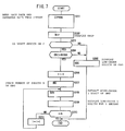
- the first program is divided into two parts, an initial processing operation executed at first when the ignition switch 24 is turned on (see FIG. 4) and an integration processing operation executed thereafter (see FIG. 5).
- trip data and odometer data are read from the EEPROM 62 in the first step S1.
- the trip data and the odometer data form data on the accumulated mileage recorded in the integration processing operation to be described later.
- the data serves as the basis for display on the trip meter 30 and the odometer 32.
- the trip data can be reset as necessary to zero by the operation of the reset switch 26.
- the odometer data remains unchanged even with the operation of the reset switch 26, indicating the total accumulated mileage of the motorcycle 12.
- the trip data is in units of 0.1 [km] in accordance with the trip meter 30.
- the odometer data is in units of 1 [km] in accordance with the odometer 32.
- trip data values will be referred to as TRIP and odometer data values will be referred to as ODO.
- ODO 135224 [km] when the ignition switch 24 is turned on.
- step S2 TRIP is displayed on the trip meter 30.
- TRIP which is binary data, is translated to a corresponding decimal value and then information on a specific numeric value of each digit and a corresponding segment to be displayed is supplied to the LCD driver 66.
- the information on the segment is set such that the numeric value is right-justified when displayed.
- step S3 the signal of the reset switch 26 is checked. If the reset switch 26 is on, the operation proceeds to step S4. If the reset switch 26 is off, the operation proceeds to step S10. It should be noted that, since the execution time of step S1 and step S2 is extremely brief, the operation proceeds to step S4 if the reset switch 26 is on simultaneously when the ignition switch 24 is turned on.
- step S4 a check is made as to whether or not ODO exceeds 99999 which is the maximum 5-digit value to be displayed on the odometer 32. If ODO >99999, the operation proceeds to step S5. If ODO ⁇ 99999, the operation proceeds to step S10.
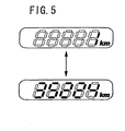
- step S6 the parameter ODO_A is displayed in the odometer 32.
- step S7 execution of step S6 causes the numeral "1" representing the portion of the 6th digit and higher-order ones of ODO is displayed in the odometer 32 for one second.
- step S7 parameter ODO_B representing the low-order five digits of ODO is obtained and displayed in the odometer 32. Specifically, the parameter ODO_B obtained through ODO_B ⁇ ODO - ODO_A x 100000 is displayed in the odometer 32 through the same processing as in step S2. After the parameter ODO_B has been displayed in the odometer 32, one second is waited through timer processing and then the operation proceeds to step S8.
- step S7 causes the numeral "35224" representing the portion of the low-order five digits of ODO is displayed in the odometer 32 for one second.
- step S8 a counter I having an initial reading of 0 is incremented through I ⁇ I + 1.
- step S10 the portion of the low-order five digits of ODO is redisplayed in the odometer 32 in the same manner as in step S7. Execution of step S10 completes the initial processing operation and the operation proceeds to the integration processing operation.
- the signal of the reset switch 26 is checked in the first step S101. If the reset switch 26 is on, the operation proceeds to step S102. If the reset switch 26 is off, the operation proceeds to step S104.
- step S102 the trip data is reset through TRIP ⁇ 0.
- step S103 the trip data reset to 0 is recorded in the EEPROM 62.
- step 104 the signal of the divider circuit 64 is checked to determine whether or not a divided pulse is generated. If it is confirmed that the divided pulse has been generated, the operation proceeds to step S105. If it is determined that the divided pulse has not been generated, the operation returns to step S101.
- the divider circuit 64 divides the pulse generated by the speed sensor 14 and supplies the CPU 56 with one divided pulse for each distance driven of 0.1 [km].
- step S105 the trip data is incremented through TRIP ⁇ TRIP + 1.
- step S106 the trip data is recorded in EEPROM 62 and updated.
- step S107 a counter C having an initial reading of 0 is incremented through C ⁇ C + 1.
- step S109 since the counter C, which is incremented in units of 0.1 [km], reads 10, the odometer data ODO in units of 1 [km] is incremented through ODO ⁇ ODO + 1.
- step S110 the counter C is reset through C ⁇ 0.
- step S111 the odometer data ODO is recorded in EEPROM 62 and updated. Even if ODO is in the state of an overflow by exceeding 99999 which is the maximum 5-digit value to be displayed on the odometer 32 at this time, that ODO data is directly recorded in the EEPROM 62. That is, if ODO is evaluated as a decimal number, recording the portion representing the sixth digit and higher-order ones in the EEPROM 62 allows that particular portion to be used as information indicating the number of times the overflow has occurred (hereinafter referred to as an "overflow count"). In practice, ODO may be recorded in the EEPROM 62 as binary data without having to convert the same to a corresponding decimal number.
- step S112 the trip data TRIP is displayed in the trip meter 30 as in step S2.
- the low-order 5-digit portion of ODO is also displayed in the odometer 32 as in step S10.
- the display may be changed as follows between before and after the occurrence of the overflow if the high-order digit of the numeric value to be displayed is 0. Specifically, if the low-order five digits of ODO read "00705,” the high-order "0" may be omitted to give a display of the three digits of "705" before the occurrence of the overflow. After the occurrence of the overflow, a display of the complete five digits of "00705" may be given. This allows the occurrence of the overflow to be determined depending on whether "0" is displayed in the high-order digit, if the low-order five digits of ODO range from "00001" to "09999.”
- step S101 The operation thereafter returns to step S101.
- the operations of steps from S101 through S112 are then repeatedly executed until the ignition switch 24 is turned off.
- the EEPROM 62 takes a long time in recording data and also has a limited number of times it can be reprogrammed. In view of these limitations, an arrangement may be made to record data in a lump at one time when the ignition switch 24 is turned off, instead of recording the trip data and the odometer data in a step-by-step fashion as in steps S106 and S111, respectively.
- a predetermined power off delay circuit may herein be used to introduce a delay time in turning power off relative to the control unit 50.
- the control unit 50 is allowed to recognize that the ignition switch 24 has been turned off and then let the trip data and the odometer data recorded in a lump in the EEPROM 62. Further, the counter C may be recorded in the EEPROM 62 and counting be continued based on the reading of the counter C at the end of the last session.
- an arrangement may also be made to execute the operations of steps from S101 through S103, and from S104 through S112, through an interrupt of an on signal of the reset switch 26 and a divided pulse of the divider circuit 64, respectively.
- the mileage display system 10 records ODO as is in the EEPROM 62 when ODO exceeds 99999 which is the maximum 5-digit value to be displayed on the odometer 32.
- ODO exceeds 99999 which is the maximum 5-digit value to be displayed on the odometer 32.
- a comparison is made of ODO with a threshold value 999999. If ODO > 99999, the portion representing the sixth digit and higher-order ones of ODO is displayed in the odometer 32, which allows the operator to recognize the overflow count.
- the mileage display system 10 can therefore be built compactly and at low cost. In particular, in the motorcycle 12, air resistance must be taken into consideration as the mileage display system 10 receives wind from the forward direction. Keeping the body of the mileage display system 10 compact helps prevent the air resistance from increasing.
- the display of the overflow count is enabled only if the reset switch 26 is turned on simultaneously when the ignition switch 24 is turned on. A choice can therefore be made by the operator to display or not to display the overflow count as he or she desires.
- the reset switch 26, which has conventionally been made available can also serve as an interface for giving instructions of the operator's intention whether he or she likes to display the overflow count or not. This suppresses a cost increase.
- the display of the overflow count is brief extending only for the first one second.
- the display does not therefore obstruct the view of the operator.
- setting the display time of the overflow count to three seconds or less will prevent the display from obstructing the view of the operator. More preferably, the time should be set to 0.5 seconds or more and 3 seconds or less.
- the odometer data represents the total accumulated mileage of the motorcycle 12, requiring no frequent check. It is sufficient to allow the operator to check an accurate value for a predetermined period of time immediately after the ignition switch 24 has been turned on.
- the odometer 32 in the mileage display system 10 is capable of displaying a value greater than the actual number of digits. A hardware modification may therefore be made to make the number of display digits smaller (e.g., four digits).
- the operation according to the second program will be described.
- the second program represents the same processing as that performed in the integration processing operation in the first program.
- the second program differs from the first program in the initial processing operation only.
- step S204 the low-order five digits of ODO are displayed in the odometer 32 to complete the initial processing operation. If the condition of the branch decision made in step S204 is met, on the other hand, the operation proceeds to step S206.
- step S206 1 is substituted for the initial value of the counter I.
- step S208 a high-order I digit of ODO is extracted and substituted for a predetermined parameter P.
- the high-order I digit of ODO is extracted through the same procedure as described in step S5.
- step S209 the low-order five digits of the parameter P are displayed in the odometer 32. Specifically, if I ⁇ 5, the parameter P value is directly displayed in the odometer 32. If I > 5, the low-order five digits of the parameter P, or "35224,” is displayed in the odometer 32. Thereafter, one second is waited through timer processing and then the operation proceeds to step S210.
- step S211 the counter I is incremented through I ⁇ I + 1. Then the operation proceeds to step S208.
- steps from S208 through S211 are repeatedly executed based on the value of the counter I as described in the foregoing.
- This causes the odometer data ODO that scrolls from the highest-order digit toward lower-order digits to be displayed in the odometer 32.
- the following values are displayed sequentially at one-second intervals as shown in FIG. 8: "1", “13", “135", “1352”, “13522", and "35224".
- the operator can therefore recognize an accurate odometer data value even if ODO includes six digits or more.
- the odometer data is displayed through scrolling which is extremely simple and easily recognizable. The operator can therefore recognize the odometer data of six digits or more without having check with an operator's manual or the like.
- the operation according to the third program will be described.
- the third program represents the same processing as that performed in the integration processing operation in the first program.
- the third program differs from the first program in the initial processing operation only.
- step S3 reset switch check
- step S303 ODO is compared with the threshold 99999 as in step S4. If ODO > 99999, the operation proceeds to step S304. If ODO ⁇ 99999, the operation proceeds to step S306.
- step 5304 the portion representing the sixth digit and higher-order ones of ODO is extracted and substituted for the parameter ODO_A as in step S5.
- step S305 the parameter ODO_A is displayed in the odometer 32 as in step S6. Then, one second is waited and the operation proceeds to step S306.
- step S306 the parameter ODO_B indicating the low-order five digits of ODO is obtained and displayed in the odometer 32. Thereafter, the initial processing is terminated and the operation proceeds to the integration processing operation (see FIG. 5).
- the portion representing the sixth digit and higher-order ones of ODO is displayed automatically in the odometer 32 for one second when the ignition switch is turned on. This allows an accurate value of ODO comprising six digits or more to be recognized with the five-digit odometer 32.
- the portion representing the sixth digit and higher-order ones of ODO is displayed regardless of whether the reset switch 26 or the like is operated or not. This eliminates the need for referring to an operator's manual or the like.
- step S203 in the second program for determining the state of the reset switch 26 may be omitted.
- step S111 ODO indicating the accumulated mileage is directly recorded in the EEPROM 62.
- the low-order five digits of ODO and the portion representing the sixth digit and higher-order ones of ODO may nonetheless be recorded separately.
- the portion representing the sixth digit and higher-order ones of ODO can be displayed as information showing the overflow count.
Abstract
Description
Japanese Patent Laid-open No. Hei 11-118509
- 10:
- MILEAGE DISPLAY SYSTEM
- 12:
- MOTORCYCLE
- 14:
- SPEED SENSOR
- 22:
- DISPLAY UNIT
- 24:
- IGNITION SWITCH
- 26:
- RESET SWITCH
- 30:
- TRIP METER
- 32:
- ODOMETER
- 50:
- CONTROL UNIT
- 52:
- BATTERY
- 56:
- CPU
- 58:
- RAM
- 60:
- ROM
- 62:
- EEPROM
- 64:
- DIVIDER CIRCUIT
- 66:
- LCD DRIVER
- 54:
- POWER CIRCUIT
- 66:
- LCD DRIVER
- 62:
- TRIP DATA | ODOMETER DATA
- S1:
- READ TRIP DATA AND ODOMETER DATA FROM EEPROM
- S2:
- DISPLAY TRIP
- S3:
- IS RESET SWITCH ON?
- S5:
- EXTRACT PORTION REPRESENTING THE SIXTH DIGIT AND HIGHER-ORDER ONES OF ODO
- S6:
- DISPLAY PORTION REPRESENTING THE SIXTH DIGIT AND HIGHER-ORDER ONES OF ODO FOR 1 SECOND
- S7:
- DISPLAY LOW-ORDER FIVE DIGITS OF ODO FOR 1 SECOND
- S10:
- DISPLAY LOW-ORDER FIVE DIGITS OF ODO
- S101:
- IS RESET SWITCH ON?
- S103:
- RECORD TRIP DATA IN EEPROM
- S104:
- IS PULSE GENERATED?
- S106:
- RECORD TRIP DATA IN EEPROM
- S111:
- RECORD ODOMETER DATA IN EEPROM
- S112:
- DISPLAY DATA ON TRIP METER AND ODOMETER
- S201:
- READ TRIP DATA AND ODOMETER DATA FROM EEPROM
- S202:
- DISPLAY TRIP
- S203:
- IS RESET SWITCH ON?
- S205:
- DISPLAY LOW-ORDER DIGITS OF ODO
- S207:
- CHECK NUMBER OF DIGITS N OF ODO
- S208:
- EXTRACT HIGH-
ORDER 1 DIGIT OF ODO - S209:
- DISPLAY LOW-
ORDER 5 DIGITS FOR 1 SECOND - S301:
- READ TRIP DATA AND ODOMETER DATA FROM EEPROM
- S302:
- DISPLAY TRIP
- S304:
- EXTRACT PORTION REPRESENTING THE SIXTH DIGIT AND HIGHER-ORDER ONES OF ODO
- S305:
- DISPLAY PORTION REPRESENTING THE SIXTH DIGIT AND HIGHER-ORDER ONES OF ODO FOR 1 SECOND
- S306:
- DISPLAY LOW-
ORDER 5 DIGITS OF ODO
Claims (5)
- A mileage display system (10) for displaying on a first meter (32) capable of displaying a predetermined number of display digits an accumulated distance traveled by a vehicle, or an accumulated mileage, comprising:wherein the arithmetic operation unit records the accumulated mileage in a predetermined recording unit and, if the accumulated mileage recorded in the recording unit exceeds a maximum value of display as established by the predetermined number of display digits when the main switch (24) is operated, displays on the first meter (32) for a predetermined period of time a numeric value of digits of higher order than the predetermined number of display digits of the accumulated mileage.an arithmetic operation unit operatively connected to a main switch (24) of the vehicle and obtaining the accumulated mileage by accumulating a pulse signal produced according to running of the vehicle,
- A mileage display system (10) for displaying on a first meter (32) capable of displaying a predetermined number of display digits an accumulated distance traveled by a vehicle, or an accumulated mileage, comprising:wherein the arithmetic operation unit records the accumulated mileage in a predetermined recording unit and, if the reset switch (26) is simultaneously operated when the main switch (24) is operated and if the accumulated mileage recorded in the recording unit exceeds a maximum value of display as established by the predetermined number of display digits, displays on the first meter (32) for a predetermined period of time a numeric value of digits of higher order than the predetermined number of display digits of the accumulated mileage.a second meter (30), a reading of the accumulated mileage on which is reset to zero when a reset switch (26) is operated; andan arithmetic operation unit operatively connected to a main switch (24) of the vehicle and obtaining the accumulated mileage by accumulating a pulse signal produced according to running of the vehicle,
- The mileage display system (10) according to any of the preceding claims,
wherein the arithmetic operation unit, after the lapse of the predetermined period of time, displays on the first meter (32) a numeric value corresponding to the low-order digits according to the predetermined number of display digits of the accumulated mileage. - The mileage display system (10) according to any of the preceding claims,
wherein the arithmetic operation unit displays the numeric value of the digits of higher order than the predetermined number of display digits and the numeric value corresponding to the low-order digits according to the predetermined number of display digits, each of the accumulated mileage, alternately on the first meter (32), a predetermined number of times. - The mileage display system (10) according to any of the preceding claims,
wherein the arithmetic operation unit displays on the first meter (32) a value of the accumulated mileage that scrolls from the highest-order digit toward lower-order digits.
Applications Claiming Priority (2)
| Application Number | Priority Date | Filing Date | Title |
|---|---|---|---|
| JP2004018134 | 2004-01-27 | ||
| JP2004018134A JP4417124B2 (en) | 2004-01-27 | 2004-01-27 | Mileage display device |
Publications (2)
| Publication Number | Publication Date |
|---|---|
| EP1559996A1 true EP1559996A1 (en) | 2005-08-03 |
| EP1559996B1 EP1559996B1 (en) | 2015-07-29 |
Family
ID=34650755
Family Applications (1)
| Application Number | Title | Priority Date | Filing Date |
|---|---|---|---|
| EP05000160.1A Expired - Fee Related EP1559996B1 (en) | 2004-01-27 | 2005-01-05 | Mileage display system |
Country Status (4)
| Country | Link |
|---|---|
| US (1) | US7212107B2 (en) |
| EP (1) | EP1559996B1 (en) |
| JP (1) | JP4417124B2 (en) |
| CN (1) | CN100453975C (en) |
Families Citing this family (10)
| Publication number | Priority date | Publication date | Assignee | Title |
|---|---|---|---|---|
| JP4325664B2 (en) * | 2006-11-24 | 2009-09-02 | いすゞ自動車株式会社 | Vehicle display device |
| IES20100735A2 (en) * | 2009-08-23 | 2012-03-14 | David James Harris | Clock for motorcycle |
| US9367967B2 (en) * | 2009-09-29 | 2016-06-14 | GM Global Technology Operations LLC | Systems and methods for odometer monitoring |
| JP5279692B2 (en) * | 2009-12-11 | 2013-09-04 | 本田技研工業株式会社 | Vehicle meter device |
| US20110196888A1 (en) * | 2010-02-10 | 2011-08-11 | Apple Inc. | Correlating Digital Media with Complementary Content |
| US9336240B2 (en) | 2011-07-15 | 2016-05-10 | Apple Inc. | Geo-tagging digital images |
| USD800144S1 (en) * | 2016-06-29 | 2017-10-17 | Naturalmotion Ltd. | Display screen or portion thereof with graphical user interface |
| WO2019003504A1 (en) * | 2017-06-30 | 2019-01-03 | オムロン株式会社 | Seismic sensor and earthquake determination method |
| US10227007B1 (en) * | 2018-04-18 | 2019-03-12 | N.S. International, Ltd. | Seamlessly integrated instrument panel display |
| CN108896071B (en) * | 2018-05-16 | 2021-12-28 | 成都雅骏新能源汽车科技股份有限公司 | Judgment method for checking vehicle mileage data |
Citations (5)
| Publication number | Priority date | Publication date | Assignee | Title |
|---|---|---|---|---|
| US4298865A (en) | 1978-07-26 | 1981-11-03 | Sharp Kabushiki Kaisha | Display device for electronic calculator or the like |
| EP0274045A1 (en) * | 1986-11-28 | 1988-07-13 | IVECO FIAT S.p.A. | Electronic odometer |
| US4803707A (en) * | 1987-12-21 | 1989-02-07 | Ncr Corporation | Nonvolatile electronic odometer with excess write cycle protection |
| JPH11118509A (en) | 1997-10-13 | 1999-04-30 | Kansei Corp | Integrator |
| US6188972B1 (en) * | 1997-10-15 | 2001-02-13 | Kansei Corporation | Integrating device and integrating method |
Family Cites Families (2)
| Publication number | Priority date | Publication date | Assignee | Title |
|---|---|---|---|---|
| US4642787A (en) * | 1984-07-30 | 1987-02-10 | Motorola, Inc. | Field presettable electronic odometer |
| CN2122375U (en) * | 1991-03-15 | 1992-11-18 | 朱江 | Combined bicycle's travelling distance gauge |
-
2004
- 2004-01-27 JP JP2004018134A patent/JP4417124B2/en not_active Expired - Fee Related
-
2005
- 2005-01-05 EP EP05000160.1A patent/EP1559996B1/en not_active Expired - Fee Related
- 2005-01-17 CN CNB2005100023220A patent/CN100453975C/en not_active Expired - Fee Related
- 2005-01-21 US US11/040,455 patent/US7212107B2/en active Active
Patent Citations (5)
| Publication number | Priority date | Publication date | Assignee | Title |
|---|---|---|---|---|
| US4298865A (en) | 1978-07-26 | 1981-11-03 | Sharp Kabushiki Kaisha | Display device for electronic calculator or the like |
| EP0274045A1 (en) * | 1986-11-28 | 1988-07-13 | IVECO FIAT S.p.A. | Electronic odometer |
| US4803707A (en) * | 1987-12-21 | 1989-02-07 | Ncr Corporation | Nonvolatile electronic odometer with excess write cycle protection |
| JPH11118509A (en) | 1997-10-13 | 1999-04-30 | Kansei Corp | Integrator |
| US6188972B1 (en) * | 1997-10-15 | 2001-02-13 | Kansei Corporation | Integrating device and integrating method |
Non-Patent Citations (1)
| Title |
|---|
| PATENT ABSTRACTS OF JAPAN vol. 1999, no. 09 30 July 1999 (1999-07-30) * |
Also Published As
| Publication number | Publication date |
|---|---|
| JP4417124B2 (en) | 2010-02-17 |
| JP2005214644A (en) | 2005-08-11 |
| CN100453975C (en) | 2009-01-21 |
| CN1648606A (en) | 2005-08-03 |
| EP1559996B1 (en) | 2015-07-29 |
| US20050165523A1 (en) | 2005-07-28 |
| US7212107B2 (en) | 2007-05-01 |
Similar Documents
| Publication | Publication Date | Title |
|---|---|---|
| US7212107B2 (en) | Odometer system and method for a vehicle | |
| US4739482A (en) | Motor vehicle maintenance interval monitor | |
| US6407663B1 (en) | Multi-function display meter system for a motorcycle | |
| WO2008156422A1 (en) | Vehicle display function | |
| JP5655709B2 (en) | Vehicle display device | |
| WO1999021137A1 (en) | Taximeter penalty device | |
| JP5787161B2 (en) | Vehicle instrument | |
| JP2003072419A (en) | Instrument for automobile | |
| US20080191853A1 (en) | Pulse Generating Device, and Vehicle Display Apparatus Having the Device | |
| JPH03114930A (en) | Electronic distance recorder | |
| JP4577558B2 (en) | Mileage display device | |
| JPH0128891B2 (en) | ||
| JPS631522B2 (en) | ||
| JPS62110116A (en) | Electronic odometer | |
| JPS6134603B2 (en) | ||
| JP2005134293A (en) | Display for for vehicle | |
| JP2917794B2 (en) | Electronic odometer | |
| KR940011325B1 (en) | Drive meter display device of vehicle | |
| JPS59230109A (en) | Electronic instrument board | |
| JP2005157742A (en) | On-vehicle analog meter | |
| JP3265932B2 (en) | Electronic odometer, mileage writing device, and mileage writing method | |
| JPH10332419A (en) | Electronic meter for car | |
| JP5217962B2 (en) | Vehicle information display device | |
| JPS6121854B2 (en) | ||
| JPH11118509A (en) | Integrator |
Legal Events
| Date | Code | Title | Description |
|---|---|---|---|
| PUAI | Public reference made under article 153(3) epc to a published international application that has entered the european phase |
Free format text: ORIGINAL CODE: 0009012 |
|
| 17P | Request for examination filed |
Effective date: 20050105 |
|
| AK | Designated contracting states |
Kind code of ref document: A1 Designated state(s): AT BE BG CH CY CZ DE DK EE ES FI FR GB GR HU IE IS IT LI LT LU MC NL PL PT RO SE SI SK TR |
|
| AX | Request for extension of the european patent |
Extension state: AL BA HR LV MK YU |
|
| AKX | Designation fees paid |
Designated state(s): DE FR GB IT |
|
| 17Q | First examination report despatched |
Effective date: 20060630 |
|
| GRAP | Despatch of communication of intention to grant a patent |
Free format text: ORIGINAL CODE: EPIDOSNIGR1 |
|
| INTG | Intention to grant announced |
Effective date: 20150430 |
|
| GRAS | Grant fee paid |
Free format text: ORIGINAL CODE: EPIDOSNIGR3 |
|
| GRAA | (expected) grant |
Free format text: ORIGINAL CODE: 0009210 |
|
| AK | Designated contracting states |
Kind code of ref document: B1 Designated state(s): DE FR GB IT |
|
| REG | Reference to a national code |
Ref country code: GB Ref legal event code: FG4D |
|
| REG | Reference to a national code |
Ref country code: DE Ref legal event code: R096 Ref document number: 602005047080 Country of ref document: DE |
|
| REG | Reference to a national code |
Ref country code: FR Ref legal event code: PLFP Year of fee payment: 12 |
|
| PGFP | Annual fee paid to national office [announced via postgrant information from national office to epo] |
Ref country code: FR Payment date: 20151208 Year of fee payment: 12 |
|
| PGFP | Annual fee paid to national office [announced via postgrant information from national office to epo] |
Ref country code: DE Payment date: 20151229 Year of fee payment: 12 |
|
| REG | Reference to a national code |
Ref country code: DE Ref legal event code: R097 Ref document number: 602005047080 Country of ref document: DE |
|
| PLBE | No opposition filed within time limit |
Free format text: ORIGINAL CODE: 0009261 |
|
| STAA | Information on the status of an ep patent application or granted ep patent |
Free format text: STATUS: NO OPPOSITION FILED WITHIN TIME LIMIT |
|
| 26N | No opposition filed |
Effective date: 20160502 |
|
| GBPC | Gb: european patent ceased through non-payment of renewal fee |
Effective date: 20160105 |
|
| REG | Reference to a national code |
Ref country code: DE Ref legal event code: R084 Ref document number: 602005047080 Country of ref document: DE |
|
| PG25 | Lapsed in a contracting state [announced via postgrant information from national office to epo] |
Ref country code: GB Free format text: LAPSE BECAUSE OF NON-PAYMENT OF DUE FEES Effective date: 20160105 |
|
| PG25 | Lapsed in a contracting state [announced via postgrant information from national office to epo] |
Ref country code: IT Free format text: LAPSE BECAUSE OF NON-PAYMENT OF DUE FEES Effective date: 20160105 |
|
| REG | Reference to a national code |
Ref country code: DE Ref legal event code: R119 Ref document number: 602005047080 Country of ref document: DE |
|
| REG | Reference to a national code |
Ref country code: FR Ref legal event code: ST Effective date: 20170929 |
|
| PG25 | Lapsed in a contracting state [announced via postgrant information from national office to epo] |
Ref country code: FR Free format text: LAPSE BECAUSE OF NON-PAYMENT OF DUE FEES Effective date: 20170131 |
|
| PG25 | Lapsed in a contracting state [announced via postgrant information from national office to epo] |
Ref country code: DE Free format text: LAPSE BECAUSE OF NON-PAYMENT OF DUE FEES Effective date: 20170801 |