EP1559904A1 - Valve body, fluid injector and process for manufacturing a valve body - Google Patents
Valve body, fluid injector and process for manufacturing a valve body Download PDFInfo
- Publication number
- EP1559904A1 EP1559904A1 EP04001801A EP04001801A EP1559904A1 EP 1559904 A1 EP1559904 A1 EP 1559904A1 EP 04001801 A EP04001801 A EP 04001801A EP 04001801 A EP04001801 A EP 04001801A EP 1559904 A1 EP1559904 A1 EP 1559904A1
- Authority
- EP
- European Patent Office
- Prior art keywords
- needle
- area
- valve body
- seat
- cartridge
- Prior art date
- Legal status (The legal status is an assumption and is not a legal conclusion. Google has not performed a legal analysis and makes no representation as to the accuracy of the status listed.)
- Granted
Links
Images

Classifications
-
- F—MECHANICAL ENGINEERING; LIGHTING; HEATING; WEAPONS; BLASTING
- F02—COMBUSTION ENGINES; HOT-GAS OR COMBUSTION-PRODUCT ENGINE PLANTS
- F02M—SUPPLYING COMBUSTION ENGINES IN GENERAL WITH COMBUSTIBLE MIXTURES OR CONSTITUENTS THEREOF
- F02M61/00—Fuel-injectors not provided for in groups F02M39/00 - F02M57/00 or F02M67/00
- F02M61/16—Details not provided for in, or of interest apart from, the apparatus of groups F02M61/02 - F02M61/14
- F02M61/18—Injection nozzles, e.g. having valve seats; Details of valve member seated ends, not otherwise provided for
-
- F—MECHANICAL ENGINEERING; LIGHTING; HEATING; WEAPONS; BLASTING
- F02—COMBUSTION ENGINES; HOT-GAS OR COMBUSTION-PRODUCT ENGINE PLANTS
- F02M—SUPPLYING COMBUSTION ENGINES IN GENERAL WITH COMBUSTIBLE MIXTURES OR CONSTITUENTS THEREOF
- F02M61/00—Fuel-injectors not provided for in groups F02M39/00 - F02M57/00 or F02M67/00
- F02M61/04—Fuel-injectors not provided for in groups F02M39/00 - F02M57/00 or F02M67/00 having valves, e.g. having a plurality of valves in series
- F02M61/08—Fuel-injectors not provided for in groups F02M39/00 - F02M57/00 or F02M67/00 having valves, e.g. having a plurality of valves in series the valves opening in direction of fuel flow
-
- F—MECHANICAL ENGINEERING; LIGHTING; HEATING; WEAPONS; BLASTING
- F02—COMBUSTION ENGINES; HOT-GAS OR COMBUSTION-PRODUCT ENGINE PLANTS
- F02M—SUPPLYING COMBUSTION ENGINES IN GENERAL WITH COMBUSTIBLE MIXTURES OR CONSTITUENTS THEREOF
- F02M51/00—Fuel-injection apparatus characterised by being operated electrically
- F02M51/06—Injectors peculiar thereto with means directly operating the valve needle
- F02M51/0603—Injectors peculiar thereto with means directly operating the valve needle using piezoelectric or magnetostrictive operating means
Definitions
- the invention relates to a valve body, a fluid injector and a method for producing a valve body.
- the valve body comprises a cartridge, with a recess that forms an injection nozzle on one end.
- the valve body further comprises a needle, that is arranged in the recess and closes the injection nozzle, if it rests with its seat area on a needle seat of the cartridge.
- Fluid injectors in particular fuel injectors for diesel or gasoline internal combustion engines, comprise a housing, an actuator unit and a valve body.
- the valve body comprises a needle that opens or closes a nozzle and in that way controls the injection of fuel.
- actuator units with a piezoelectric actuator are used. They have the advantage of having a very fast response time to actuating signals and enable like that multiple injections into a cylinder of the internal combustion engine during one working cycle of the cylinder.
- the fluid pressure is increased.
- the fluid injectors are supplied with fuel which has a pressure of up to 200 bars.
- WO 03/016707 A1 discloses a fluid injector with a connector to a fuel supply, a housing, an actuator unit, and a valve body.
- the housing is double tubed and has a recess, which takes up the actuator unit.
- the actuator unit comprises a piezoelectric actuator, which acts on the needle. Between the walls of the double tube-shaped housing the fuel is led from the connector to a fuel inlet of the valve body.
- the valve body has a housing part with a recess, that takes up a needle. Depending on the position of the needle a nozzle is opened or closed and respectively fuel is injected or not.
- the object of the invention is to create a valve body, a fluid injector and a method for manufacturing a valve body, which is simple and ensures a defined and constant spray characteristic.
- the invention is distinguished by a valve body with a cartridge with a recess, that forms on one end an injection nozzle, and with a needle, that is arranged in the recess and closes the injection nozzle, if it rests with its seat area on an needle seat of the cartridge.
- the area of the cartridge adjacent to the needle seat has a cylindrically-shaped outer contour and the needle has a cylindrically-shaped area adjacent to the seat area.
- the area adjacent to the needle seat and the cylindrically-shaped area have the same diameter.
- valve body comprises conically-shaped needle seat and a conically-shaped seat area of the needle.
- the cartridge has an area adjacent to the area adjacent to the needle seat where the outer diameter of the cartridge is increasing in the direction away from the nozzle.
- a fluid injector according to the invention is distinguished by a housing, an actuator and the valve body.
- the aspect of the invention concerning the method for manufacturing a valve body is distinguished by a valve body with a cartridge with a recess, that forms an injection nozzle on one end, and with a needle, that is arranged in the recess and closes the injection nozzle, if it rests with its seat area on a needle seat of the cartridge.
- the area of the cartridge adjacent to the needle seat has a cylindrically-shaped outer contour and the needle has a cylindrically-shaped area adjacent to the seat area.
- the method comprises the steps of inserting the needle in the recess and bringing it to rest with its seat area on the needle seat and grinding the cylindrically-shaped outer contour of the cartridge and cylindrically-shaped area of the needle together.
- the cylindrically-shaped area of the cartridge adjacent to the needle seat and the cylindrically-shaped area adjacent to the seat area of the needle enable easy control of a constant velocity of the grinding wheel, which rotates parallel to the cylindrically-shaped areas and to the axis of the needle. That way the grinding direction is perpendicular to the surface of the areas which easily enables direct control of the sealing diameter by the grinding process, which is essential for precise control of fluid flow through the injection nozzle.
- the grinding includes a honing process. This has the advantage that the diameter of the cylindrically-shaped areas can be adjusted very precisely. It has further the advantage that it enables a very good finish of the surface, which is important for preventing deposit formation.
- the grinding includes a lapping process. This enables an excellent finish of the surface, which is important for preventing deposit formation on the surface.
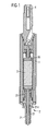
- a fluid injector that is used as a fuel injector for an internal combustion engine, comprises a housing 1, a valve body 2, an actuator unit 3 and a fuel connector 4.
- the fuel connector 4 is designed to be connected to a high pressure fuel chamber of the internal combustion engine, where fuel is stored under high pressure, for example under the pressure of about 200 Bar.
- the housing 1 is preferably formed out of a double-tubed housing. In the space between the walls of the double-tubed housing the fuel is led from the fuel connector to a fuel inlet 214 of the valve body 2.
- the valve body 2 comprises a cartridge 21, which is permanently fixed to the housing 1 at one of its free ends, preferably by welding, especially laser-welding.
- the cartridge 21 comprises a recess 211 ( Figure 2) which forms at one of its ends an injection nozzle 213 and which takes in a needle 22.
- a spring rest 24 is connected to the needle 22.
- a return spring 25 rests on the spring rest 24 and pretensions the needle 22 in a direction away from the injection nozzle 213. In that way the needle 22 closes the injection nozzle 213 with its tip 23, if no further external forces act on the needle 22.
- the fuel is led from the fuel inlet 214 in the space between the needle 22 and the wall of the recess 213 of the cartridge 21 to the injection nozzle 213.
- the needle 22 further comprises a guided zone 221, by which the needle 22 is guided within the recess 213.
- the needle seat 215 and the seat area 224 are conically shaped in a preferred embodiment. This enables to set a desired spray angle.
- the area 216 of the cartridge 21 adjacent to the needle seat 215 has a cylindrically-shaped outer contour.
- the needle 22 has a cylindrically-shaped area 223 adjacent to the seat area 224.
- the area 216 adjacent to the needle seat 215 and the cylindrically-shaped area 223 have the same diameter. The same diameter is preferably achieved by inserting the needle 22 in the recess 213 of the cartridge and bringing it to rest with its seat area 224 on the needle seat 215. Afterwards the cylindrically-shaped outer contour of the cartridge 21 and cylindrically-shaped area 223 of the needle are grinded together.
- the grinding process preferably includes a honing process and/or a lapping process.
- the grinding wheel makes, for example an axial oscillatory movement parallel to the axis of the needle 22 and the needle and the cartridge are turned around their axis.
- a paste or fluid is used which contains the cutting material.
- the area of the cartridge adjacent to the area 216 to the needle seat 224 has preferably an outer diameter of the cartridge 21 which is increasing in the direction away from the injection nozzle 213.
Landscapes
- Engineering & Computer Science (AREA)
- Chemical & Material Sciences (AREA)
- Combustion & Propulsion (AREA)
- Mechanical Engineering (AREA)
- General Engineering & Computer Science (AREA)
- Fuel-Injection Apparatus (AREA)
Abstract
Description
- Figure 1
- a fluid injector,
- Figure 2
- a valve body,
- Figure 3
- an enlargement of parts of the valve body.
Claims (7)
- Valve body with a cartridge (21) with a recess (211), that forms an injection nozzle (213) on one end and with a needle (22), that is arranged in the recess (211) and closes the injection nozzle (213), if it rests with its seat area (224) on a needle seat (215) of the cartridge (21), where an area (216) of the cartridge (21) adjacent to the needle seat (215) has a cylindrically-shaped outer contour and the needle (22) has a cylindrically-shaped area (223) adjacent to the seat area (224) and where the area (216) of the cartridge (21) adjacent to the needle seat (215) and the cylindrically-shaped area (223) have the same diameter.
- Valve body in accordance with claim 1, with the needle seat (215) and the seat area (224) of the needle (22) being conically shaped.
- Valve body in accordance with one of the preceding claims, where the cartridge (21) has an area adjacent to the area (216) adjacent to the needle seat (224) where the outer diameter of the cartridge (21) is increasing in the direction away from the injection nozzle (213).
- Fluid injector with a housing (1), an actuator unit (3) and a valve body (2) in accordance with one of the preceding claims.
- Method for manufacturing a valve body with a cartridge (21) with a recess (211), that forms on one end an injection nozzle (213), and with a needle (22), that is arranged in the recess (221) and closes the injection nozzle (213), if it rests with its seat area (224) on a needle seat (215) of the cartridge (21), where the area (216) of the cartridge (21) adjacent to the needle seat (215) has a cylindrically-shaped outer contour and the needle (22) has cylindrically-shaped area (223) adjacent to the seat area (224) with the following steps:inserting the needle (22) in the recess (221) and bringing it to rest with its seat area (224) on the needle seat (215),grinding the cylindrically-shaped outer contour of the cartridge (21) and the cylindrically-shaped area (223) of the needle (22) together.
- Method for manufacturing a valve body in accordance with claim 5 where the grinding includes a honing process.
- Method for manufacturing a valve body in accordance with one of claims 5 or 6, where the grinding includes a lapping process.
Priority Applications (6)
| Application Number | Priority Date | Filing Date | Title |
|---|---|---|---|
| EP04001801A EP1559904B1 (en) | 2004-01-28 | 2004-01-28 | Valve body, fluid injector and process for manufacturing a valve body |
| DE602004005152T DE602004005152T2 (en) | 2004-01-28 | 2004-01-28 | Valve body, fluid injector and method of manufacturing a valve body |
| US10/597,510 US8172161B2 (en) | 2004-01-28 | 2004-12-15 | Valve body, fluid injector and process for manufacturing a valve body |
| CN2004800409304A CN1906404B (en) | 2004-01-28 | 2004-12-15 | Valve body, fluid injector, and process for making valve body |
| JP2006549942A JP2007534875A (en) | 2004-01-28 | 2004-12-15 | Valve body, fluid injector, and method of manufacturing valve body |
| PCT/EP2004/053474 WO2005075814A1 (en) | 2004-01-28 | 2004-12-15 | Valve body, fluid injector and process for manufacturing a valve body |
Applications Claiming Priority (1)
| Application Number | Priority Date | Filing Date | Title |
|---|---|---|---|
| EP04001801A EP1559904B1 (en) | 2004-01-28 | 2004-01-28 | Valve body, fluid injector and process for manufacturing a valve body |
Publications (2)
| Publication Number | Publication Date |
|---|---|
| EP1559904A1 true EP1559904A1 (en) | 2005-08-03 |
| EP1559904B1 EP1559904B1 (en) | 2007-03-07 |
Family
ID=34639393
Family Applications (1)
| Application Number | Title | Priority Date | Filing Date |
|---|---|---|---|
| EP04001801A Expired - Lifetime EP1559904B1 (en) | 2004-01-28 | 2004-01-28 | Valve body, fluid injector and process for manufacturing a valve body |
Country Status (6)
| Country | Link |
|---|---|
| US (1) | US8172161B2 (en) |
| EP (1) | EP1559904B1 (en) |
| JP (1) | JP2007534875A (en) |
| CN (1) | CN1906404B (en) |
| DE (1) | DE602004005152T2 (en) |
| WO (1) | WO2005075814A1 (en) |
Cited By (4)
| Publication number | Priority date | Publication date | Assignee | Title |
|---|---|---|---|---|
| EP2863048A1 (en) | 2013-10-21 | 2015-04-22 | C.R.F. Società Consortile Per Azioni | Fuel electro-injector for a fuel injection system for an internal combustion engine |
| EP3018340A1 (en) | 2014-11-05 | 2016-05-11 | C.R.F. Società Consortile per Azioni | Fuel electro-injector atomizer for a fuel injection system for an internal combustion engine |
| EP3165759A1 (en) | 2015-11-09 | 2017-05-10 | C.R.F. Società Consortile Per Azioni | Injection method for injecting fuel into a combustion chamber of an internal-combustion engine, atomizer of a fuel electro-injector for carrying ut such injection method, and process for the producing such atomizer |
| EP3299610A1 (en) | 2016-09-22 | 2018-03-28 | C.R.F. Società Consortile Per Azioni | Fuel electro-injector atomizer, in particular for a diesel cycle engine |
Families Citing this family (8)
| Publication number | Priority date | Publication date | Assignee | Title |
|---|---|---|---|---|
| US8800895B2 (en) * | 2008-08-27 | 2014-08-12 | Woodward, Inc. | Piloted variable area fuel injector |
| US20110073071A1 (en) * | 2009-09-30 | 2011-03-31 | Woodward Governor Company | Internally Nested Variable-Area Fuel Nozzle |
| US9683739B2 (en) * | 2009-11-09 | 2017-06-20 | Woodward, Inc. | Variable-area fuel injector with improved circumferential spray uniformity |
| US9038601B2 (en) | 2011-11-01 | 2015-05-26 | Cummins Inc. | Flow limiter assembly for a fuel system of an internal combustion engine |
| CN102493903A (en) * | 2011-12-05 | 2012-06-13 | 北京理工大学 | Method for manufacturing high-flow gas nozzle |
| WO2013122317A1 (en) * | 2012-02-13 | 2013-08-22 | 현대중공업 주식회사 | Check valve driving device for injecting gas |
| CN103481027B (en) * | 2013-08-30 | 2016-03-09 | 哈尔滨汽轮机厂有限责任公司 | A processing method for a spool used in an oil cooler |
| RU2651925C1 (en) * | 2017-07-19 | 2018-04-24 | Федеральное государственное бюджетное образовательное учреждение высшего образования "Ярославский государственный технический университет" ФГБОУВО "ЯГТУ" | Atomizer of valve injector for internal combustion engine and method of its assembly |
Citations (3)
| Publication number | Priority date | Publication date | Assignee | Title |
|---|---|---|---|---|
| DE3941151A1 (en) * | 1989-12-13 | 1991-06-20 | Bosch Gmbh Robert | IC engine fuel injection nozzle - has additional spring load provided by follow-up pistons installed in distance piece |
| US5522550A (en) * | 1992-06-10 | 1996-06-04 | Robert Bosch Gmbh | Injection nozzle for internal combustion engines |
| US20020026923A1 (en) * | 2000-03-16 | 2002-03-07 | Dietmar Bertsch | Injection nozzle and a method for forming a fuel-air mixture |
Family Cites Families (24)
| Publication number | Priority date | Publication date | Assignee | Title |
|---|---|---|---|---|
| US2338744A (en) * | 1941-08-26 | 1944-01-11 | Martin Motors Inc | Injection nozzle for internal combustion engines |
| US3042317A (en) * | 1959-12-09 | 1962-07-03 | Parker Hannifin Corp | Variable area valve |
| FR2068857A5 (en) * | 1969-10-24 | 1971-09-03 | Sofredi | |
| US4030668A (en) * | 1976-06-17 | 1977-06-21 | The Bendix Corporation | Electromagnetically operated fuel injection valve |
| US4129254A (en) * | 1977-09-12 | 1978-12-12 | General Motors Corporation | Electromagnetic unit fuel injector |
| US4219154A (en) * | 1978-07-10 | 1980-08-26 | The Bendix Corporation | Electronically controlled, solenoid operated fuel injection system |
| US4350301A (en) * | 1980-06-25 | 1982-09-21 | The Bendix Corporation | Flow controlled pressure regulating device |
| US4487369A (en) * | 1982-01-11 | 1984-12-11 | Essex Group, Inc. | Electromagnetic fuel injector with improved discharge structure |
| US4923169A (en) * | 1987-12-23 | 1990-05-08 | Siemens-Bendix Automotive Electronics L.P. | Multi-stream thin edge orifice disks for valves |
| JPH01160165U (en) | 1988-04-28 | 1989-11-07 | ||
| WO1991011609A1 (en) | 1990-01-26 | 1991-08-08 | Orbital Engine Company Proprietary Limited | Fuel injector nozzle |
| JPH06220671A (en) | 1992-07-29 | 1994-08-09 | Mitsubishi Kasei Corp | Equipment for cleaning oily deposits |
| DE4442764A1 (en) * | 1994-12-01 | 1996-06-05 | Bosch Gmbh Robert | Fuel injection valve for internal combustion engines |
| JPH08226363A (en) | 1995-02-20 | 1996-09-03 | Zexel Corp | Fuel injection nozzle |
| JPH09177638A (en) | 1995-12-26 | 1997-07-11 | Zexel Corp | Fuel injection nozzle |
| DE19638025A1 (en) | 1996-09-18 | 1998-03-19 | Bosch Gmbh Robert | Fuel injector with integrated spark plug |
| DE19701288C2 (en) * | 1997-01-16 | 1999-10-14 | Daimler Benz Ag | Valve for dispensing fluids |
| US6296199B1 (en) * | 1998-08-27 | 2001-10-02 | Robert Bosch Gmbh | Fuel injection valve |
| DE19843534A1 (en) * | 1998-09-23 | 2000-03-30 | Bosch Gmbh Robert | Fuel injector |
| DE50010902D1 (en) * | 1999-04-20 | 2005-09-15 | Siemens Ag | fluid metering |
| GB0000863D0 (en) * | 2000-01-15 | 2000-03-08 | Delphi Diesel Systems Ltd | Fuel injector |
| US20030025006A1 (en) * | 2001-08-03 | 2003-02-06 | Scarbrough William T. | Impinging sheet atomizer nozzle |
| WO2003016707A1 (en) | 2001-08-08 | 2003-02-27 | Siemens Aktiengesellschaft | Dosing device |
| DE10205970A1 (en) * | 2002-02-14 | 2003-09-04 | Bosch Gmbh Robert | Fuel injection valve for internal combustion engines |
-
2004
- 2004-01-28 EP EP04001801A patent/EP1559904B1/en not_active Expired - Lifetime
- 2004-01-28 DE DE602004005152T patent/DE602004005152T2/en not_active Expired - Lifetime
- 2004-12-15 WO PCT/EP2004/053474 patent/WO2005075814A1/en not_active Ceased
- 2004-12-15 JP JP2006549942A patent/JP2007534875A/en active Pending
- 2004-12-15 CN CN2004800409304A patent/CN1906404B/en not_active Expired - Fee Related
- 2004-12-15 US US10/597,510 patent/US8172161B2/en not_active Expired - Fee Related
Patent Citations (3)
| Publication number | Priority date | Publication date | Assignee | Title |
|---|---|---|---|---|
| DE3941151A1 (en) * | 1989-12-13 | 1991-06-20 | Bosch Gmbh Robert | IC engine fuel injection nozzle - has additional spring load provided by follow-up pistons installed in distance piece |
| US5522550A (en) * | 1992-06-10 | 1996-06-04 | Robert Bosch Gmbh | Injection nozzle for internal combustion engines |
| US20020026923A1 (en) * | 2000-03-16 | 2002-03-07 | Dietmar Bertsch | Injection nozzle and a method for forming a fuel-air mixture |
Cited By (9)
| Publication number | Priority date | Publication date | Assignee | Title |
|---|---|---|---|---|
| EP2863048A1 (en) | 2013-10-21 | 2015-04-22 | C.R.F. Società Consortile Per Azioni | Fuel electro-injector for a fuel injection system for an internal combustion engine |
| WO2015059639A1 (en) | 2013-10-21 | 2015-04-30 | C.R.F. Societa' Consortile Per Azioni | Fuel electro-injector atomizer for a fuel injection system for an internal combustion engine |
| DE202014010759U1 (en) | 2013-10-21 | 2016-07-28 | C.R.F. Società Consortile Per Azioni | Electronic fuel injection atomizer for a fuel injection system for an internal combustion engine |
| EP3018340A1 (en) | 2014-11-05 | 2016-05-11 | C.R.F. Società Consortile per Azioni | Fuel electro-injector atomizer for a fuel injection system for an internal combustion engine |
| WO2016071853A1 (en) | 2014-11-05 | 2016-05-12 | C.R.F. Societa' Consortile Per Azioni | Fuel electro-injector atomizer for a fuel injection system for an internal combustion engine |
| DE202015009430U1 (en) | 2014-11-05 | 2017-07-28 | C.R.F. Società Consortile Per Azioni | Atomizer of an electric injection nozzle for an injection system for an internal combustion engine |
| EP3165759A1 (en) | 2015-11-09 | 2017-05-10 | C.R.F. Società Consortile Per Azioni | Injection method for injecting fuel into a combustion chamber of an internal-combustion engine, atomizer of a fuel electro-injector for carrying ut such injection method, and process for the producing such atomizer |
| EP3299610A1 (en) | 2016-09-22 | 2018-03-28 | C.R.F. Società Consortile Per Azioni | Fuel electro-injector atomizer, in particular for a diesel cycle engine |
| US11008991B2 (en) | 2016-09-22 | 2021-05-18 | C.R.F. Società Consortile Per Azioni | Fuel electro-injector atomizer, in particular for a diesel cycle engine |
Also Published As
| Publication number | Publication date |
|---|---|
| CN1906404A (en) | 2007-01-31 |
| CN1906404B (en) | 2010-05-26 |
| US8172161B2 (en) | 2012-05-08 |
| JP2007534875A (en) | 2007-11-29 |
| WO2005075814A1 (en) | 2005-08-18 |
| EP1559904B1 (en) | 2007-03-07 |
| US20080296415A1 (en) | 2008-12-04 |
| DE602004005152D1 (en) | 2007-04-19 |
| DE602004005152T2 (en) | 2007-07-12 |
Similar Documents
| Publication | Publication Date | Title |
|---|---|---|
| EP1559904B1 (en) | Valve body, fluid injector and process for manufacturing a valve body | |
| US5607106A (en) | Low inertia, wear-resistant valve for engine fuel injection systems | |
| EP2148082B1 (en) | Coupling arrangement for an injection valve and injection valve | |
| JP4239995B2 (en) | Fuel injection device for internal combustion engine | |
| US20110180634A1 (en) | Nozzle body, nozzle assembly and fuel injector, and method for producing a nozzle body | |
| JP2001527183A (en) | Duration control of common rail fuel injectors | |
| US20020185111A1 (en) | Common rail fuel injector for internal combustion engines, as well as a fuel system and an internal combustion engine incorporating the injector | |
| JP2003506626A (en) | Fuel injection valve and method for manufacturing a discharge opening of the valve | |
| US20080210773A1 (en) | Fuel Injection Device for Internal Combustion Engine | |
| CN100447401C (en) | fuel injection valve | |
| US4846217A (en) | Injection valve | |
| US20050145713A1 (en) | Fuel injector valve | |
| EP1088985A3 (en) | High pressure fuel injector for an internal combustion engine | |
| CN105658945A (en) | In particular the piston/fluid line arrangement of the control piston/control hole arrangement | |
| EP1559907B2 (en) | Fluid injector with means to prevent rotation of the valve needle | |
| EP1548272B1 (en) | Valve body and fluid injector with valve body | |
| US6918549B2 (en) | Fuel injector tip for control of fuel delivery | |
| EP2896811B1 (en) | Nozzle assembly and fuel injection valve for a combustion engine | |
| EP1467087A1 (en) | Spray pattern element and fuel injection valve with a spray pattern element | |
| EP1559905A1 (en) | Fluid injector with a deformable valve needle | |
| EP2711536A1 (en) | Nozzle module and injection valve | |
| EP1887216B1 (en) | Thermal compensation arrangement in an injection valve | |
| EP1568881B1 (en) | Fluid injector | |
| JP2008038716A (en) | Fuel injection valve | |
| JP4542100B2 (en) | Fuel injection valve |
Legal Events
| Date | Code | Title | Description |
|---|---|---|---|
| PUAI | Public reference made under article 153(3) epc to a published international application that has entered the european phase |
Free format text: ORIGINAL CODE: 0009012 |
|
| AK | Designated contracting states |
Kind code of ref document: A1 Designated state(s): AT BE BG CH CY CZ DE DK EE ES FI FR GB GR HU IE IT LI LU MC NL PT RO SE SI SK TR |
|
| AX | Request for extension of the european patent |
Extension state: AL LT LV MK |
|
| 17P | Request for examination filed |
Effective date: 20060203 |
|
| AKX | Designation fees paid |
Designated state(s): DE FR GB IT |
|
| GRAP | Despatch of communication of intention to grant a patent |
Free format text: ORIGINAL CODE: EPIDOSNIGR1 |
|
| GRAS | Grant fee paid |
Free format text: ORIGINAL CODE: EPIDOSNIGR3 |
|
| GRAA | (expected) grant |
Free format text: ORIGINAL CODE: 0009210 |
|
| AK | Designated contracting states |
Kind code of ref document: B1 Designated state(s): DE FR GB IT |
|
| REG | Reference to a national code |
Ref country code: GB Ref legal event code: FG4D |
|
| REF | Corresponds to: |
Ref document number: 602004005152 Country of ref document: DE Date of ref document: 20070419 Kind code of ref document: P |
|
| ET | Fr: translation filed | ||
| PLBE | No opposition filed within time limit |
Free format text: ORIGINAL CODE: 0009261 |
|
| STAA | Information on the status of an ep patent application or granted ep patent |
Free format text: STATUS: NO OPPOSITION FILED WITHIN TIME LIMIT |
|
| 26N | No opposition filed |
Effective date: 20071210 |
|
| PGFP | Annual fee paid to national office [announced via postgrant information from national office to epo] |
Ref country code: GB Payment date: 20090122 Year of fee payment: 6 |
|
| GBPC | Gb: european patent ceased through non-payment of renewal fee |
Effective date: 20100128 |
|
| PG25 | Lapsed in a contracting state [announced via postgrant information from national office to epo] |
Ref country code: GB Free format text: LAPSE BECAUSE OF NON-PAYMENT OF DUE FEES Effective date: 20100128 |
|
| REG | Reference to a national code |
Ref country code: FR Ref legal event code: CD |
|
| REG | Reference to a national code |
Ref country code: FR Ref legal event code: PLFP Year of fee payment: 13 |
|
| REG | Reference to a national code |
Ref country code: FR Ref legal event code: PLFP Year of fee payment: 14 |
|
| REG | Reference to a national code |
Ref country code: FR Ref legal event code: PLFP Year of fee payment: 15 |
|
| PGFP | Annual fee paid to national office [announced via postgrant information from national office to epo] |
Ref country code: DE Payment date: 20180131 Year of fee payment: 15 |
|
| PGFP | Annual fee paid to national office [announced via postgrant information from national office to epo] |
Ref country code: FR Payment date: 20190123 Year of fee payment: 16 Ref country code: IT Payment date: 20190124 Year of fee payment: 16 |
|
| REG | Reference to a national code |
Ref country code: DE Ref legal event code: R119 Ref document number: 602004005152 Country of ref document: DE |
|
| PG25 | Lapsed in a contracting state [announced via postgrant information from national office to epo] |
Ref country code: DE Free format text: LAPSE BECAUSE OF NON-PAYMENT OF DUE FEES Effective date: 20190801 |
|
| PG25 | Lapsed in a contracting state [announced via postgrant information from national office to epo] |
Ref country code: FR Free format text: LAPSE BECAUSE OF NON-PAYMENT OF DUE FEES Effective date: 20200131 |
|
| PG25 | Lapsed in a contracting state [announced via postgrant information from national office to epo] |
Ref country code: IT Free format text: LAPSE BECAUSE OF NON-PAYMENT OF DUE FEES Effective date: 20200128 |