EP1559879B1 - Exhaust aftertreatment system - Google Patents
Exhaust aftertreatment system Download PDFInfo
- Publication number
- EP1559879B1 EP1559879B1 EP05001665A EP05001665A EP1559879B1 EP 1559879 B1 EP1559879 B1 EP 1559879B1 EP 05001665 A EP05001665 A EP 05001665A EP 05001665 A EP05001665 A EP 05001665A EP 1559879 B1 EP1559879 B1 EP 1559879B1
- Authority
- EP
- European Patent Office
- Prior art keywords
- exhaust gas
- reduction catalyst
- port
- particulate filter
- absorption reduction
- Prior art date
- Legal status (The legal status is an assumption and is not a legal conclusion. Google has not performed a legal analysis and makes no representation as to the accuracy of the status listed.)
- Expired - Lifetime
Links
Images


Classifications
-
- F—MECHANICAL ENGINEERING; LIGHTING; HEATING; WEAPONS; BLASTING
- F01—MACHINES OR ENGINES IN GENERAL; ENGINE PLANTS IN GENERAL; STEAM ENGINES
- F01N—GAS-FLOW SILENCERS OR EXHAUST APPARATUS FOR MACHINES OR ENGINES IN GENERAL; GAS-FLOW SILENCERS OR EXHAUST APPARATUS FOR INTERNAL-COMBUSTION ENGINES
- F01N3/00—Exhaust or silencing apparatus having means for purifying, rendering innocuous, or otherwise treating exhaust
- F01N3/08—Exhaust or silencing apparatus having means for purifying, rendering innocuous, or otherwise treating exhaust for rendering innocuous
- F01N3/0807—Exhaust or silencing apparatus having means for purifying, rendering innocuous, or otherwise treating exhaust for rendering innocuous by using absorbents or adsorbents
- F01N3/0821—Exhaust or silencing apparatus having means for purifying, rendering innocuous, or otherwise treating exhaust for rendering innocuous by using absorbents or adsorbents combined with particulate filter
-
- F—MECHANICAL ENGINEERING; LIGHTING; HEATING; WEAPONS; BLASTING
- F01—MACHINES OR ENGINES IN GENERAL; ENGINE PLANTS IN GENERAL; STEAM ENGINES
- F01N—GAS-FLOW SILENCERS OR EXHAUST APPARATUS FOR MACHINES OR ENGINES IN GENERAL; GAS-FLOW SILENCERS OR EXHAUST APPARATUS FOR INTERNAL-COMBUSTION ENGINES
- F01N13/00—Exhaust or silencing apparatus characterised by constructional features
- F01N13/009—Exhaust or silencing apparatus characterised by constructional features having two or more separate purifying devices arranged in series
-
- F—MECHANICAL ENGINEERING; LIGHTING; HEATING; WEAPONS; BLASTING
- F01—MACHINES OR ENGINES IN GENERAL; ENGINE PLANTS IN GENERAL; STEAM ENGINES
- F01N—GAS-FLOW SILENCERS OR EXHAUST APPARATUS FOR MACHINES OR ENGINES IN GENERAL; GAS-FLOW SILENCERS OR EXHAUST APPARATUS FOR INTERNAL-COMBUSTION ENGINES
- F01N13/00—Exhaust or silencing apparatus characterised by constructional features
- F01N13/009—Exhaust or silencing apparatus characterised by constructional features having two or more separate purifying devices arranged in series
- F01N13/0097—Exhaust or silencing apparatus characterised by constructional features having two or more separate purifying devices arranged in series the purifying devices are arranged in a single housing
-
- F—MECHANICAL ENGINEERING; LIGHTING; HEATING; WEAPONS; BLASTING
- F01—MACHINES OR ENGINES IN GENERAL; ENGINE PLANTS IN GENERAL; STEAM ENGINES
- F01N—GAS-FLOW SILENCERS OR EXHAUST APPARATUS FOR MACHINES OR ENGINES IN GENERAL; GAS-FLOW SILENCERS OR EXHAUST APPARATUS FOR INTERNAL-COMBUSTION ENGINES
- F01N3/00—Exhaust or silencing apparatus having means for purifying, rendering innocuous, or otherwise treating exhaust
- F01N3/08—Exhaust or silencing apparatus having means for purifying, rendering innocuous, or otherwise treating exhaust for rendering innocuous
- F01N3/0807—Exhaust or silencing apparatus having means for purifying, rendering innocuous, or otherwise treating exhaust for rendering innocuous by using absorbents or adsorbents
- F01N3/0814—Exhaust or silencing apparatus having means for purifying, rendering innocuous, or otherwise treating exhaust for rendering innocuous by using absorbents or adsorbents combined with catalytic converters, e.g. NOx absorption/storage reduction catalysts
-
- F—MECHANICAL ENGINEERING; LIGHTING; HEATING; WEAPONS; BLASTING
- F01—MACHINES OR ENGINES IN GENERAL; ENGINE PLANTS IN GENERAL; STEAM ENGINES
- F01N—GAS-FLOW SILENCERS OR EXHAUST APPARATUS FOR MACHINES OR ENGINES IN GENERAL; GAS-FLOW SILENCERS OR EXHAUST APPARATUS FOR INTERNAL-COMBUSTION ENGINES
- F01N3/00—Exhaust or silencing apparatus having means for purifying, rendering innocuous, or otherwise treating exhaust
- F01N3/08—Exhaust or silencing apparatus having means for purifying, rendering innocuous, or otherwise treating exhaust for rendering innocuous
- F01N3/0807—Exhaust or silencing apparatus having means for purifying, rendering innocuous, or otherwise treating exhaust for rendering innocuous by using absorbents or adsorbents
- F01N3/0828—Exhaust or silencing apparatus having means for purifying, rendering innocuous, or otherwise treating exhaust for rendering innocuous by using absorbents or adsorbents characterised by the absorbed or adsorbed substances
- F01N3/0842—Nitrogen oxides
-
- F—MECHANICAL ENGINEERING; LIGHTING; HEATING; WEAPONS; BLASTING
- F01—MACHINES OR ENGINES IN GENERAL; ENGINE PLANTS IN GENERAL; STEAM ENGINES
- F01N—GAS-FLOW SILENCERS OR EXHAUST APPARATUS FOR MACHINES OR ENGINES IN GENERAL; GAS-FLOW SILENCERS OR EXHAUST APPARATUS FOR INTERNAL-COMBUSTION ENGINES
- F01N3/00—Exhaust or silencing apparatus having means for purifying, rendering innocuous, or otherwise treating exhaust
- F01N3/08—Exhaust or silencing apparatus having means for purifying, rendering innocuous, or otherwise treating exhaust for rendering innocuous
- F01N3/0807—Exhaust or silencing apparatus having means for purifying, rendering innocuous, or otherwise treating exhaust for rendering innocuous by using absorbents or adsorbents
- F01N3/0871—Exhaust or silencing apparatus having means for purifying, rendering innocuous, or otherwise treating exhaust for rendering innocuous by using absorbents or adsorbents using means for controlling, e.g. purging, the absorbents or adsorbents
- F01N3/0878—Bypassing absorbents or adsorbents
-
- F—MECHANICAL ENGINEERING; LIGHTING; HEATING; WEAPONS; BLASTING
- F01—MACHINES OR ENGINES IN GENERAL; ENGINE PLANTS IN GENERAL; STEAM ENGINES
- F01N—GAS-FLOW SILENCERS OR EXHAUST APPARATUS FOR MACHINES OR ENGINES IN GENERAL; GAS-FLOW SILENCERS OR EXHAUST APPARATUS FOR INTERNAL-COMBUSTION ENGINES
- F01N3/00—Exhaust or silencing apparatus having means for purifying, rendering innocuous, or otherwise treating exhaust
- F01N3/08—Exhaust or silencing apparatus having means for purifying, rendering innocuous, or otherwise treating exhaust for rendering innocuous
- F01N3/0807—Exhaust or silencing apparatus having means for purifying, rendering innocuous, or otherwise treating exhaust for rendering innocuous by using absorbents or adsorbents
- F01N3/0871—Exhaust or silencing apparatus having means for purifying, rendering innocuous, or otherwise treating exhaust for rendering innocuous by using absorbents or adsorbents using means for controlling, e.g. purging, the absorbents or adsorbents
- F01N3/0885—Regeneration of deteriorated absorbents or adsorbents, e.g. desulfurization of NOx traps
-
- F—MECHANICAL ENGINEERING; LIGHTING; HEATING; WEAPONS; BLASTING
- F01—MACHINES OR ENGINES IN GENERAL; ENGINE PLANTS IN GENERAL; STEAM ENGINES
- F01N—GAS-FLOW SILENCERS OR EXHAUST APPARATUS FOR MACHINES OR ENGINES IN GENERAL; GAS-FLOW SILENCERS OR EXHAUST APPARATUS FOR INTERNAL-COMBUSTION ENGINES
- F01N3/00—Exhaust or silencing apparatus having means for purifying, rendering innocuous, or otherwise treating exhaust
- F01N3/08—Exhaust or silencing apparatus having means for purifying, rendering innocuous, or otherwise treating exhaust for rendering innocuous
- F01N3/10—Exhaust or silencing apparatus having means for purifying, rendering innocuous, or otherwise treating exhaust for rendering innocuous by thermal or catalytic conversion of noxious components of exhaust
- F01N3/18—Exhaust or silencing apparatus having means for purifying, rendering innocuous, or otherwise treating exhaust for rendering innocuous by thermal or catalytic conversion of noxious components of exhaust characterised by methods of operation; Control
- F01N3/20—Exhaust or silencing apparatus having means for purifying, rendering innocuous, or otherwise treating exhaust for rendering innocuous by thermal or catalytic conversion of noxious components of exhaust characterised by methods of operation; Control specially adapted for catalytic conversion
- F01N3/2006—Periodically heating or cooling catalytic reactors, e.g. at cold starting or overheating
- F01N3/2033—Periodically heating or cooling catalytic reactors, e.g. at cold starting or overheating using a fuel burner or introducing fuel into exhaust duct
-
- F—MECHANICAL ENGINEERING; LIGHTING; HEATING; WEAPONS; BLASTING
- F01—MACHINES OR ENGINES IN GENERAL; ENGINE PLANTS IN GENERAL; STEAM ENGINES
- F01N—GAS-FLOW SILENCERS OR EXHAUST APPARATUS FOR MACHINES OR ENGINES IN GENERAL; GAS-FLOW SILENCERS OR EXHAUST APPARATUS FOR INTERNAL-COMBUSTION ENGINES
- F01N3/00—Exhaust or silencing apparatus having means for purifying, rendering innocuous, or otherwise treating exhaust
- F01N3/08—Exhaust or silencing apparatus having means for purifying, rendering innocuous, or otherwise treating exhaust for rendering innocuous
- F01N3/10—Exhaust or silencing apparatus having means for purifying, rendering innocuous, or otherwise treating exhaust for rendering innocuous by thermal or catalytic conversion of noxious components of exhaust
- F01N3/18—Exhaust or silencing apparatus having means for purifying, rendering innocuous, or otherwise treating exhaust for rendering innocuous by thermal or catalytic conversion of noxious components of exhaust characterised by methods of operation; Control
- F01N3/20—Exhaust or silencing apparatus having means for purifying, rendering innocuous, or otherwise treating exhaust for rendering innocuous by thermal or catalytic conversion of noxious components of exhaust characterised by methods of operation; Control specially adapted for catalytic conversion
- F01N3/2053—By-passing catalytic reactors, e.g. to prevent overheating
-
- F—MECHANICAL ENGINEERING; LIGHTING; HEATING; WEAPONS; BLASTING
- F02—COMBUSTION ENGINES; HOT-GAS OR COMBUSTION-PRODUCT ENGINE PLANTS
- F02B—INTERNAL-COMBUSTION PISTON ENGINES; COMBUSTION ENGINES IN GENERAL
- F02B37/00—Engines characterised by provision of pumps driven at least for part of the time by exhaust
-
- F—MECHANICAL ENGINEERING; LIGHTING; HEATING; WEAPONS; BLASTING
- F02—COMBUSTION ENGINES; HOT-GAS OR COMBUSTION-PRODUCT ENGINE PLANTS
- F02M—SUPPLYING COMBUSTION ENGINES IN GENERAL WITH COMBUSTIBLE MIXTURES OR CONSTITUENTS THEREOF
- F02M31/00—Apparatus for thermally treating combustion-air, fuel, or fuel-air mixture
- F02M31/02—Apparatus for thermally treating combustion-air, fuel, or fuel-air mixture for heating
- F02M31/16—Other apparatus for heating fuel
-
- F—MECHANICAL ENGINEERING; LIGHTING; HEATING; WEAPONS; BLASTING
- F02—COMBUSTION ENGINES; HOT-GAS OR COMBUSTION-PRODUCT ENGINE PLANTS
- F02M—SUPPLYING COMBUSTION ENGINES IN GENERAL WITH COMBUSTIBLE MIXTURES OR CONSTITUENTS THEREOF
- F02M37/00—Apparatus or systems for feeding liquid fuel from storage containers to carburettors or fuel-injection apparatus; Arrangements for purifying liquid fuel specially adapted for, or arranged on, internal-combustion engines
- F02M37/22—Arrangements for purifying liquid fuel specially adapted for, or arranged on, internal-combustion engines, e.g. arrangements in the feeding system
- F02M37/32—Arrangements for purifying liquid fuel specially adapted for, or arranged on, internal-combustion engines, e.g. arrangements in the feeding system characterised by filters or filter arrangements
- F02M37/44—Filters structurally associated with pumps
-
- F—MECHANICAL ENGINEERING; LIGHTING; HEATING; WEAPONS; BLASTING
- F01—MACHINES OR ENGINES IN GENERAL; ENGINE PLANTS IN GENERAL; STEAM ENGINES
- F01N—GAS-FLOW SILENCERS OR EXHAUST APPARATUS FOR MACHINES OR ENGINES IN GENERAL; GAS-FLOW SILENCERS OR EXHAUST APPARATUS FOR INTERNAL-COMBUSTION ENGINES
- F01N2240/00—Combination or association of two or more different exhaust treating devices, or of at least one such device with an auxiliary device, not covered by indexing codes F01N2230/00 or F01N2250/00, one of the devices being
- F01N2240/36—Combination or association of two or more different exhaust treating devices, or of at least one such device with an auxiliary device, not covered by indexing codes F01N2230/00 or F01N2250/00, one of the devices being an exhaust flap
-
- F—MECHANICAL ENGINEERING; LIGHTING; HEATING; WEAPONS; BLASTING
- F01—MACHINES OR ENGINES IN GENERAL; ENGINE PLANTS IN GENERAL; STEAM ENGINES
- F01N—GAS-FLOW SILENCERS OR EXHAUST APPARATUS FOR MACHINES OR ENGINES IN GENERAL; GAS-FLOW SILENCERS OR EXHAUST APPARATUS FOR INTERNAL-COMBUSTION ENGINES
- F01N2470/00—Structure or shape of exhaust gas passages, pipes or tubes
- F01N2470/24—Concentric tubes or tubes being concentric to housing, e.g. telescopically assembled
-
- Y—GENERAL TAGGING OF NEW TECHNOLOGICAL DEVELOPMENTS; GENERAL TAGGING OF CROSS-SECTIONAL TECHNOLOGIES SPANNING OVER SEVERAL SECTIONS OF THE IPC; TECHNICAL SUBJECTS COVERED BY FORMER USPC CROSS-REFERENCE ART COLLECTIONS [XRACs] AND DIGESTS
- Y02—TECHNOLOGIES OR APPLICATIONS FOR MITIGATION OR ADAPTATION AGAINST CLIMATE CHANGE
- Y02T—CLIMATE CHANGE MITIGATION TECHNOLOGIES RELATED TO TRANSPORTATION
- Y02T10/00—Road transport of goods or passengers
- Y02T10/10—Internal combustion engine [ICE] based vehicles
- Y02T10/12—Improving ICE efficiencies
Definitions
- the present invention relates to an exhaust aftertreatment system according to the preamble of claim 1.
- Such an exhaust aftertreatment system is known from FR 2 819 549 A .
- Exhaust gas from a diesel engine is generally purified by a catalyst arranged in an exhaust pipe through which the exhaust gas flows.
- a catalyst arranged in an exhaust pipe through which the exhaust gas flows.
- an NO x -absorption reduction catalyst which has a property of oxidizing NO x in exhaust gas to temporarily absorb the same in the form of nitrate when an air/fuel ratio of the exhaust gas is lean, and conducting decomposition into NO x for reduction and purification thereof with the assistance of unburned HC and CO when the oxygen concentration in the exhaust gas is lowered.
- NO x -absorption reduction catalyst having the above-mentioned property is, for example, a catalyst made from alumina and carrying platinum and barium or a catalyst made from alumina and carrying iridium, platinum and barium.
- Particulates or particulate matter in the exhaust gas is mainly constituted by carbonic soot and a soluble organic fraction of high-boiling hydrocarbons and contains a trace of sulfate or misty sulfuric acid fraction.
- a particulate filter is conventionally arranged in the exhaust pipe through which the exhaust gas flows.
- Fig. 1 shows a conventional exhaust aftertreatment system in which reference numeral 1 generally denotes a diesel engine as an internal combustion engine.
- the engine 1 shown has a turbocharger 2 comprising a compressor 2a and a turbine 2b.
- Suction air 4 is guided via an air cleaner 3 and a suction pipe 5 into the compressor 2a of the turbocharger 2 for pressurization; the pressurized air 4 is cooled in an intercooler 6 and then is distributed via an intake manifold (not shown) into respective cylinders of the engine 1.
- the respective cylinders of the engine 1 for combustion; exhaust gas 8 discharged from the cylinders of the engine 1 is fed via an exhaust manifold 7 into the turbine 2b of the turbocharger 2.
- the exhaust gas 8 having driven the turbine 2b is discharged out of a vehicle via an exhaust pipe 9.
- a casing 10 Arranged in the exhaust pipe 9 is a casing 10 which accommodates an upstream NO x -absorption reduction catalyst 11 and a downstream particulate filter 12 integrally carrying an oxidation catalyst. Also arranged in the exhaust pipe 9 and upstream of the casing 10 is an exhaust brake 14 which is adjustable in opening degree so as to throttle the flow path of the exhaust pipe 9 to a desired opening degree.
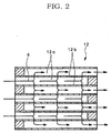
- the particulate filter 12 is of a porous honeycomb structure made of ceramics such as cordierite and having lattice-like compartmentalized passages 12a. Alternate ones of the passages 12a have plugged inlets and the remaining passages 12a with unplugged open inlets are plugged at their outlets. Thus, only the exhaust gas 8 passing through thin porous compartment walls 12b which define the passages 12a is discharged downstream while the particulates are captured and accumulated on inner surfaces of the walls 12b. The oxidation catalyst is coated to the whole of the filter 12 to an extent not to bring about clogging.
- NO x in the exhaust gas 8 is absorbed in the NO x -absorption reduction catalyst 11 in the form of nitrate so as to reduce NO x , and the particulates in the exhaust gas 8 are captured by the particulate filter 12, whereby purified exhaust gas 8 is discharged out of the vehicle.
- a technique itself for overcoming the poisoning through sulfate is known; rich combustion with an air/fuel ratio lower than theoretical air/fuel ratio and maintaining the NO x -absorption reduction catalyst 11 in a high-temperature atmosphere of approximately 650°C or more will release SO 2 from the reduction catalyst 11, thereby regenerating the reduction catalyst 11. This is difficult to carry out by controlling an operation of the diesel engine 1. Moreover, if the temperature of the exhaust gas 8 becomes approximately 700°C or more, catalyst material of the NO x -absorption reduction catalyst 11 chemically combined with sulfur will be crystallized so that detachment of sulfur becomes impossible and deterioration gradually progresses with no recovery of catalytic performance of the reduction catalyst 11, disadvantageously leading to a short service life of the reduction catalyst 11.
- the invention was made in view of the above and has its object to provide an exhaust aftertreatment system which can prevent the NO x -absorption reduction catalyst from being poisoned and deteriorated through sulfate without difficultly controlling an operation of a diesel engine, can prevent the ratio of NO x purification through the NO x -absorption reduction catalyst from being lowered and can prolong the service life thereof.
- the invention is directed to an exhaust aftertreatment system as claimed in claim 1.
- the exhaust aftertreatment system comprises an outer cylinder into which the exhaust gas having passed through the particulate filter is guided, an inner cylinder coaxially arranged in the outer cylinder and to which the NO x -absorption reduction catalyst is charged and a space between the inner and outer cylinders utilized as bypass line, said sector valve arranged at an inlet in said outer cylinder.
- a valvate cylinder is arranged in the inlet in said outer cylinder such that an axis of said valvate cylinder extends perpendicular to an axis of the outer cylinder.
- the valvate cylinder is formed with an exhaust gas guide port through which the exhaust gas having passed through the particulate filter is guided, a first port in communication with an inside of the inner cylinder and a second port in communication with the bypass line.
- a valve body Arranged in the valvate cylinder is a valve body which may be switched over between a position where the exhaust gas guide port is communicated with the first port and the second port is blocked off and a position where the exhaust gas guide port is communicated with the second port and the first port is blocked off, thereby providing the selector valve.
- the exhaust aftertreatment system may further comprise an HC addition device for adding HC to the exhaust gas upstream of the NO x -absorption reduction catalyst to produce an oxidative reaction of said HC on the reduction catalyst, reaction heat thereof being utilized to raise in temperature a catalyst bed of the reduction catalyst over a predetermined temperature so as to gasify and detach sulfate lingering on the reduction catalyst.
- an HC addition device for adding HC to the exhaust gas upstream of the NO x -absorption reduction catalyst to produce an oxidative reaction of said HC on the reduction catalyst, reaction heat thereof being utilized to raise in temperature a catalyst bed of the reduction catalyst over a predetermined temperature so as to gasify and detach sulfate lingering on the reduction catalyst.
- the NO x -absorption reduction catalyst has a downstream end integrally carrying an oxidation catalyst.
- Fig. 3 shows an example not covered by the present invention in which parts similar to those in Figs. 1 and 2 are designated by the same reference numerals and whose fundamental structure is the same as that in the conventional apparatus shown in Figs. 1 and 2.
- the example is characteristic in that, as shown in Fig. 3, a filter casing 15 is arranged in an exhaust pipe 9 through which flows exhaust gas 8 from a diesel engine 1.
- the filter casing 15 accommodates a particulate filter 12 which in turn integrally carries an oxidation catalyst.
- a catalyst casing 16 Arranged in the exhaust pipe 9 and downstream of the particulate filter 12 is a catalyst casing 16 which accommodates an NO x -absorption reduction catalyst 11.
- the exhaust pipe 9 has a bypass line 17 branched from the pipe 9 between the particulate filter 12 and the NO x -absorption reduction catalyst 11 and connected to the exhaust pipe 9 downstream of the reduction catalyst 11.
- a selector valve 18 Arranged in a connection between the exhaust pipe 9 and the bypass line 17 is a selector valve 18 which may be changed over to guide the exhaust gas 8 either into the NO x -absorption reduction catalyst 11 or into the bypass line 17.
- an HC addition device 19 for addition of HC to the exhaust gas 8 is arranged at an inlet side of the NO x -absorption reduction catalyst 11 to produce oxidative reaction on the reduction catalyst 11 of HC added by the addition device 19, reaction heat thereof being utilized to raise in temperature a catalyst bed of the reduction catalyst 11 over a predetermined temperature so as to gasify and detach sulfate lingering on the reduction catalyst 11.
- a switching valve 20 Arranged at an outlet side of the NO x -absorption reduction catalyst 11 is a switching valve 20 which prevents the exhaust gas 8 flowing in the bypass line 17 from passing into the reduction catalyst 11 when the selector valve 18 is changed over toward the bypass line 17.
- the NO x -absorption reduction catalyst 11 has a downstream end integrally carrying an oxidation catalyst.
- the particulate filter 12 which is of the porous honeycomb structure made of ceramics such as cordierite, tends to be less effected by poisoning and deterioration through sulfate in comparison with the NO x -absorption reduction catalyst 11 and therefore no problem occurs.
- the temperature of the exhaust gas 8 is raised, for example, by throttling in flow rate and increasing in pressure the exhaust gas 8 by means of the exhaust gas brake 14. This raises the temperature of the particulate filter 12 so that sulfate and SO 2 gas can be detached from the particulate filter 12 for regeneration thereof; then, the selector valve 18 is switched over toward the bypass line 17 and the switching valve 20 is closed so that sulfate and SO 2 gas discharged from the particulate filter 12 are diverted from the NO x -absorption reduction catalyst 11 to flow downstream; thus, there is no fear of them being attached as sulfate to the NO x -absorption reduction catalyst 11.
- the HC addition device 19 for addition of HC to the exhaust gas 8 is arranged at the inlet side of the NO x -absorption reduction catalyst 11. Therefore, even if some of sulfate and SO 2 gas are not captured by and pass through the particulate filter 12 and are attached as sulfate to the NO x -absorption reduction catalyst 11 for lingering, then the selector valve 18 is switched over toward the reduction catalyst 11 so as to make the exhaust gas 8 flow through the reduction catalyst 11 while HC is added by the HC addition device 19 to the exhaust gas 8 upstream of the reduction catalyst 11.
- the selector valve 18 is switched over toward the bypass line 17 to divert the exhaust gas 8 from the NO x -absorption reduction catalyst 11 while HC is added to the reduction catalyst 11 by the HC addition device 19, then relative excess air ratio to the added amount of HC is lowered to enhance the reaction selectivity of HC and NO x , whereby NO x is positively decomposed and discharged from the reduction catalyst 11 to attain satisfactory regeneration of the reduction catalyst 11.
- the discharged NO x may be reacted with said HC on the NO x -absorption reduction catalyst 11 for satisfactory reduction and purification thereof.
- the NO x -absorption reduction catalyst 11 has the downstream end integrally carrying the oxidation catalyst. Therefore, even if an amount of HC added by the HC addition device 19 to the exhaust gas 8 is too much to produce the oxidative reaction of all of said HC on the NO x -absorption reduction catalyst 11, unoxidized HC is oxidized on the oxidation catalyst, thereby preventing the unoxidized HC from leaking to outside.
- Fig. 4 shows the embodiment of the present invention in which parts similar to those in Fig. 3 are represented by the same reference numerals and whose fundamental structure is the same as that in Fig. 3.
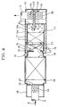
- This embodiment is characteristic in that, as shown in Fig. 4, the exhaust gas 8 having passed through the particulate filter 12 is guided to an outer cylinder 16a within which coaxially arranged is an inner cylinder 16b charged with the NO x -absorption reduction catalyst 11, a space between the inner and outer cylinders 16b and 16a being utilized as bypass line 17, a selector valve 18 being arranged in an inlet in said outer cylinder 16a.
- a valvate cylinder 21 is arranged in the inlet in the outer cylinder 16a such that an axis of the valvate cylinder 21 extends perpendicular to an axis of the outer cylinder 16a.
- the valvate cylinder 21 is formed with the exhaust gas guide port 22 through which the exhaust gas 8 having passed through the particulate filter 12 is guided, a first port 23 in communication with an inside of the inner cylinder 16b and a second port 24 in communication with the bypass line 17.
- a valve body 25 is arranged in the valvate cylinder 21 such that it may be switched over either into a position (shown in solid lines in Fig.
- the filter casing 15 has an upstream end integrally formed with an upstream exhaust gas chamber 28 which in turn is partitioned from the filter casing 15 by a plate 27 with a number of communication pores 26.
- the exhaust pipe 9 extending from the diesel engine 1 passes through the exhaust gas chamber 28.
- An inserted portion of the exhaust pipe 9 in the exhaust gas chamber 28 is formed with a number of communication pores 29.
- the bypass line 17 formed in the outer cylinder 16a has a downstream end, and the inner cylinder 16b has a corresponding downstream end formed with a number of communication pores 30.
- the bypass line 17 and the downstream end of the inner cylinder 16b are closed by a separate plate 31 formed in the outer cylinder 16a to provide a downstream exhaust gas chamber 32 in the downstream end of the outer cylinder 16a.
- a communicating tube or tubes 33 pass through the separate plate 31.
- a downstream end of the tube 33 or each of the tubes 33 is formed with a number of communication pores 34.
- the exhaust pipe 9 extends to outside from the exhaust gas chamber 32 in the outer cylinder 16a partitioned by the separate plate 31.
- a portion of the exhaust pipe 9 inside of the exhaust gas chamber 32 in the outer cylinder 16a is formed with a number of communication pores 35.
- the HC addition device 19 is arranged as shown in solid lines at a connection between the filter casing 15 and the outer cylinder 16a; alternatively, as shown in imaginary lines in Fig. 4, it may be arranged adjacent to the first port 23 for the selector valve 18.
- the exhaust gas 8 is guided via the exhaust pipe 9 and the communication pores 29 into the upstream exhaust gas chamber 28 where it is further guided via the communication pores 26 of the plate 27 into the particulate filter 12 in the filter casing 15.
- the selector valve 18 is switched over to the position (shown in solid lines in Fig. 4) where the exhaust gas guide port 22 is communicated with the first port 23 and the second port 24 is blocked off, the exhaust gas 8 having passed through the particulate filter 12 is guided via the ports 22 and 23 to the NO x -absorption reduction catalyst 11, then passing through the communicating tube or tubes 33, the communication pores 34 into the downstream exhaust gas chamber 32 where it is guided via the communication pores 35 into the exhaust pipe 9, flowing further to downstream.
- the same effects and advantages as those in the example shown in Fig. 3 can be obtained.
- the NO x -absorption reduction catalyst 11, the bypass line 17 and the selector valve 18 can be accommodated in the single cylindrical body compact in size, advantageously resulting in no limitation in mountability to the vehicle.
Landscapes
- Engineering & Computer Science (AREA)
- Chemical & Material Sciences (AREA)
- Combustion & Propulsion (AREA)
- Mechanical Engineering (AREA)
- General Engineering & Computer Science (AREA)
- Chemical Kinetics & Catalysis (AREA)
- Health & Medical Sciences (AREA)
- Toxicology (AREA)
- Exhaust Gas After Treatment (AREA)
- Processes For Solid Components From Exhaust (AREA)
- Exhaust Gas Treatment By Means Of Catalyst (AREA)
Description
- The present invention relates to an exhaust aftertreatment system according to the preamble of claim 1. Such an exhaust aftertreatment system is known from
FR 2 819 549 A - Exhaust gas from a diesel engine is generally purified by a catalyst arranged in an exhaust pipe through which the exhaust gas flows. Known as this kind of catalyst is an NOx-absorption reduction catalyst which has a property of oxidizing NOx in exhaust gas to temporarily absorb the same in the form of nitrate when an air/fuel ratio of the exhaust gas is lean, and conducting decomposition into NOx for reduction and purification thereof with the assistance of unburned HC and CO when the oxygen concentration in the exhaust gas is lowered.
- Known as this kind of NOx-absorption reduction catalyst having the above-mentioned property is, for example, a catalyst made from alumina and carrying platinum and barium or a catalyst made from alumina and carrying iridium, platinum and barium.
- Particulates or particulate matter in the exhaust gas is mainly constituted by carbonic soot and a soluble organic fraction of high-boiling hydrocarbons and contains a trace of sulfate or misty sulfuric acid fraction. In order to reduce a discharged amount of particulates from the engine, a particulate filter is conventionally arranged in the exhaust pipe through which the exhaust gas flows.
- Fig. 1 shows a conventional exhaust aftertreatment system in which reference numeral 1 generally denotes a diesel engine as an internal combustion engine. The engine 1 shown has a
turbocharger 2 comprising acompressor 2a and aturbine 2b.Suction air 4 is guided via anair cleaner 3 and asuction pipe 5 into thecompressor 2a of theturbocharger 2 for pressurization; the pressurizedair 4 is cooled in anintercooler 6 and then is distributed via an intake manifold (not shown) into respective cylinders of the engine 1. the respective cylinders of the engine 1 for combustion;exhaust gas 8 discharged from the cylinders of the engine 1 is fed via anexhaust manifold 7 into theturbine 2b of theturbocharger 2. Theexhaust gas 8 having driven theturbine 2b is discharged out of a vehicle via anexhaust pipe 9. - Arranged in the
exhaust pipe 9 is acasing 10 which accommodates an upstream NOx-absorption reduction catalyst 11 and adownstream particulate filter 12 integrally carrying an oxidation catalyst. Also arranged in theexhaust pipe 9 and upstream of thecasing 10 is anexhaust brake 14 which is adjustable in opening degree so as to throttle the flow path of theexhaust pipe 9 to a desired opening degree. - A specific structure of the
particulate filter 12 is shown in Fig. 2. Theparticulate filter 12 is of a porous honeycomb structure made of ceramics such as cordierite and having lattice-like compartmentalized passages 12a. Alternate ones of the passages 12a have plugged inlets and the remaining passages 12a with unplugged open inlets are plugged at their outlets. Thus, only theexhaust gas 8 passing through thin porous compartment walls 12b which define the passages 12a is discharged downstream while the particulates are captured and accumulated on inner surfaces of the walls 12b. The oxidation catalyst is coated to the whole of thefilter 12 to an extent not to bring about clogging. - More specifically, according to the exhaust aftertreatment system shown in Fig. 1, NOx in the
exhaust gas 8 is absorbed in the NOx-absorption reduction catalyst 11 in the form of nitrate so as to reduce NOx, and the particulates in theexhaust gas 8 are captured by theparticulate filter 12, whereby purifiedexhaust gas 8 is discharged out of the vehicle. - The above-mentioned exhaust aftertreatment system with the particulate filter is disclosed, for example, in
JP 2001-317332 A - However, there exists SO2 in the
exhaust gas 8 from the engine 1 which derives from sulfur in the fuel. Such SO2 is oxidized on the NOx-absorption reduction catalyst 11 just like NOx, disadvantageously resulting in sulfate. Sulfate is more stable than nitrate so that the NOx-absorption reduction catalyst 11 is poisoned and deteriorated by sulfate, leading to a problem that absorption of NOx becomes impossible and NOx purification ratio is lowered. There has been no specific proposals which have been developed to a practical level on the problem. - A technique itself for overcoming the poisoning through sulfate is known; rich combustion with an air/fuel ratio lower than theoretical air/fuel ratio and maintaining the NOx-
absorption reduction catalyst 11 in a high-temperature atmosphere of approximately 650°C or more will release SO2 from thereduction catalyst 11, thereby regenerating thereduction catalyst 11. This is difficult to carry out by controlling an operation of the diesel engine 1. Moreover, if the temperature of theexhaust gas 8 becomes approximately 700°C or more, catalyst material of the NOx-absorption reduction catalyst 11 chemically combined with sulfur will be crystallized so that detachment of sulfur becomes impossible and deterioration gradually progresses with no recovery of catalytic performance of thereduction catalyst 11, disadvantageously leading to a short service life of thereduction catalyst 11. - The invention was made in view of the above and has its object to provide an exhaust aftertreatment system which can prevent the NOx-absorption reduction catalyst from being poisoned and deteriorated through sulfate without difficultly controlling an operation of a diesel engine, can prevent the ratio of NOx purification through the NOx-absorption reduction catalyst from being lowered and can prolong the service life thereof.
- The invention is directed to an exhaust aftertreatment system as claimed in claim 1.
- The exhaust aftertreatment system comprises an outer cylinder into which the exhaust gas having passed through the particulate filter is guided, an inner cylinder coaxially arranged in the outer cylinder and to which the NOx-absorption reduction catalyst is charged and a space between the inner and outer cylinders utilized as bypass line, said sector valve arranged at an inlet in said outer cylinder.
- In this instance, a valvate cylinder is arranged in the inlet in said outer cylinder such that an axis of said valvate cylinder extends perpendicular to an axis of the outer cylinder. The valvate cylinder is formed with an exhaust gas guide port through which the exhaust gas having passed through the particulate filter is guided, a first port in communication with an inside of the inner cylinder and a second port in communication with the bypass line. Arranged in the valvate cylinder is a valve body which may be switched over between a position where the exhaust gas guide port is communicated with the first port and the second port is blocked off and a position where the exhaust gas guide port is communicated with the second port and the first port is blocked off, thereby providing the selector valve.
- The exhaust aftertreatment system may further comprise an HC addition device for adding HC to the exhaust gas upstream of the NOx-absorption reduction catalyst to produce an oxidative reaction of said HC on the reduction catalyst, reaction heat thereof being utilized to raise in temperature a catalyst bed of the reduction catalyst over a predetermined temperature so as to gasify and detach sulfate lingering on the reduction catalyst.
- In this instance, preferably, the NOx-absorption reduction catalyst has a downstream end integrally carrying an oxidation catalyst.
- Now, embodiments of the invention will be described in conjunction with the attached drawings.
-
- Fig. 1
- is a schematic view showing a conventional exhaust aftertreatment system;
- Fig. 2
- is a sectional view showing particulars of a particulate filter;
- Fig. 3
- is a schematic view showing an example of the background art; and
- Fig. 4
- is a sectional view showing main portions of the embodiment of the invention.
- Fig. 3 shows an example not covered by the present invention in which parts similar to those in Figs. 1 and 2 are designated by the same reference numerals and whose fundamental structure is the same as that in the conventional apparatus shown in Figs. 1 and 2. The example is characteristic in that, as shown in Fig. 3, a
filter casing 15 is arranged in anexhaust pipe 9 through which flowsexhaust gas 8 from a diesel engine 1. Thefilter casing 15 accommodates aparticulate filter 12 which in turn integrally carries an oxidation catalyst. Arranged in theexhaust pipe 9 and downstream of theparticulate filter 12 is acatalyst casing 16 which accommodates an NOx-absorption reduction catalyst 11. Theexhaust pipe 9 has abypass line 17 branched from thepipe 9 between theparticulate filter 12 and the NOx-absorption reduction catalyst 11 and connected to theexhaust pipe 9 downstream of thereduction catalyst 11. Arranged in a connection between theexhaust pipe 9 and thebypass line 17 is aselector valve 18 which may be changed over to guide theexhaust gas 8 either into the NOx-absorption reduction catalyst 11 or into thebypass line 17. - In this example, an
HC addition device 19 for addition of HC to theexhaust gas 8 is arranged at an inlet side of the NOx-absorption reduction catalyst 11 to produce oxidative reaction on thereduction catalyst 11 of HC added by theaddition device 19, reaction heat thereof being utilized to raise in temperature a catalyst bed of thereduction catalyst 11 over a predetermined temperature so as to gasify and detach sulfate lingering on thereduction catalyst 11. - Arranged at an outlet side of the NOx-
absorption reduction catalyst 11 is aswitching valve 20 which prevents theexhaust gas 8 flowing in thebypass line 17 from passing into thereduction catalyst 11 when theselector valve 18 is changed over toward thebypass line 17. - The NOx-
absorption reduction catalyst 11 has a downstream end integrally carrying an oxidation catalyst. - Next, mode of operation of the embodiment will be described.
- There exists SO2 in the
exhaust gas 8 from the diesel engine 1 which derives from sulfur in the fuel. Such SO2 is captured by and oxidized on theparticulate filter 12, resulting in lingering thereof as sulfate. However, theparticulate filter 12, which is of the porous honeycomb structure made of ceramics such as cordierite, tends to be less effected by poisoning and deterioration through sulfate in comparison with the NOx-absorption reduction catalyst 11 and therefore no problem occurs. Thus, most of SO2 in theexhaust gas 8 is captured by theparticulate filter 12 and hardly proceed to the NOx-absorption reduction catalyst 11, so that there is no fear of thereduction catalyst 11 being poisoned and deteriorated by sulfate, resulting in no inhibition of NOx absorption and no lowering of NOx purification ratio. - When sulfate has been accumulated on the
particulate filter 12 to some extent, the temperature of theexhaust gas 8 is raised, for example, by throttling in flow rate and increasing in pressure theexhaust gas 8 by means of theexhaust gas brake 14. This raises the temperature of theparticulate filter 12 so that sulfate and SO2 gas can be detached from theparticulate filter 12 for regeneration thereof; then, theselector valve 18 is switched over toward thebypass line 17 and the switchingvalve 20 is closed so that sulfate and SO2 gas discharged from theparticulate filter 12 are diverted from the NOx-absorption reduction catalyst 11 to flow downstream; thus, there is no fear of them being attached as sulfate to the NOx-absorption reduction catalyst 11. - In the example, the
HC addition device 19 for addition of HC to theexhaust gas 8 is arranged at the inlet side of the NOx-absorption reduction catalyst 11. Therefore, even if some of sulfate and SO2 gas are not captured by and pass through theparticulate filter 12 and are attached as sulfate to the NOx-absorption reduction catalyst 11 for lingering, then theselector valve 18 is switched over toward thereduction catalyst 11 so as to make theexhaust gas 8 flow through thereduction catalyst 11 while HC is added by theHC addition device 19 to theexhaust gas 8 upstream of thereduction catalyst 11. This produces the oxidative reaction of HC on the NOx-absorption reduction catalyst 11, reaction heat thereof being utilized to raise in temperature the catalyst bed of thereduction catalyst 11 over the predetermined temperature; immediately thereafter theselector valve 18 is switched over toward thebypass line 17 so that theexhaust gas 8 is diverted from the NOx-absorption reduction catalyst 11 while HC is added again to thereduction catalyst 11. As a result, relative excess ratio to the added amount of HC is lowered to attain rich atmosphere with the air/fuel ration smaller than the theoretical air/fuel ratio so that sulfate lingering on the NOx-absorption reduction catalyst 11 is gasified and detached. - If periodically the
selector valve 18 is switched over toward thebypass line 17 to divert theexhaust gas 8 from the NOx-absorption reduction catalyst 11 while HC is added to thereduction catalyst 11 by theHC addition device 19, then relative excess air ratio to the added amount of HC is lowered to enhance the reaction selectivity of HC and NOx, whereby NOx is positively decomposed and discharged from thereduction catalyst 11 to attain satisfactory regeneration of thereduction catalyst 11. The discharged NOx may be reacted with said HC on the NOx-absorption reduction catalyst 11 for satisfactory reduction and purification thereof. - Moreover, the NOx-
absorption reduction catalyst 11 has the downstream end integrally carrying the oxidation catalyst. Therefore, even if an amount of HC added by theHC addition device 19 to theexhaust gas 8 is too much to produce the oxidative reaction of all of said HC on the NOx-absorption reduction catalyst 11, unoxidized HC is oxidized on the oxidation catalyst, thereby preventing the unoxidized HC from leaking to outside. - Thus, without difficultly controlling the operation of the diesel engine 1, poisoning and deterioration of the NOx-
absorption reduction catalyst 11 through sulfate can be prevented, lowering of the ratio of Nox purification through thereduction catalyst 11 can be averted and the service life of thereduction catalyst 11 can be prolonged. - Fig. 4 shows the embodiment of the present invention in which parts similar to those in Fig. 3 are represented by the same reference numerals and whose fundamental structure is the same as that in Fig. 3. This embodiment is characteristic in that, as shown in Fig. 4, the
exhaust gas 8 having passed through theparticulate filter 12 is guided to an outer cylinder 16a within which coaxially arranged is aninner cylinder 16b charged with the NOx-absorption reduction catalyst 11, a space between the inner andouter cylinders 16b and 16a being utilized asbypass line 17, aselector valve 18 being arranged in an inlet in said outer cylinder 16a. - In the embodiment, a
valvate cylinder 21 is arranged in the inlet in the outer cylinder 16a such that an axis of thevalvate cylinder 21 extends perpendicular to an axis of the outer cylinder 16a. Thevalvate cylinder 21 is formed with the exhaustgas guide port 22 through which theexhaust gas 8 having passed through theparticulate filter 12 is guided, afirst port 23 in communication with an inside of theinner cylinder 16b and asecond port 24 in communication with thebypass line 17. Avalve body 25 is arranged in thevalvate cylinder 21 such that it may be switched over either into a position (shown in solid lines in Fig. 4) where the exhaustgas guide port 22 is communicated with thefirst port 23 and thesecond port 24 is blocked off or into a position (shown in imaginary lines in Fig. 4) where the exhaustgas guide port 22 is communicated with thesecond port 24 and thefirst port 23 is blocked off, thereby providing theselector valve 18. - The
filter casing 15 has an upstream end integrally formed with an upstreamexhaust gas chamber 28 which in turn is partitioned from thefilter casing 15 by aplate 27 with a number of communication pores 26. Theexhaust pipe 9 extending from the diesel engine 1 passes through theexhaust gas chamber 28. An inserted portion of theexhaust pipe 9 in theexhaust gas chamber 28 is formed with a number of communication pores 29. - The
bypass line 17 formed in the outer cylinder 16a has a downstream end, and theinner cylinder 16b has a corresponding downstream end formed with a number of communication pores 30. Thebypass line 17 and the downstream end of theinner cylinder 16b are closed by aseparate plate 31 formed in the outer cylinder 16a to provide a downstreamexhaust gas chamber 32 in the downstream end of the outer cylinder 16a. A communicating tube ortubes 33 pass through theseparate plate 31. A downstream end of thetube 33 or each of thetubes 33 is formed with a number of communication pores 34. Theexhaust pipe 9 extends to outside from theexhaust gas chamber 32 in the outer cylinder 16a partitioned by theseparate plate 31. A portion of theexhaust pipe 9 inside of theexhaust gas chamber 32 in the outer cylinder 16a is formed with a number of communication pores 35. - In Fig. 4, the
HC addition device 19 is arranged as shown in solid lines at a connection between thefilter casing 15 and the outer cylinder 16a; alternatively, as shown in imaginary lines in Fig. 4, it may be arranged adjacent to thefirst port 23 for theselector valve 18. - In the embodiment shown in Fig. 4, the
exhaust gas 8 is guided via theexhaust pipe 9 and the communication pores 29 into the upstreamexhaust gas chamber 28 where it is further guided via the communication pores 26 of theplate 27 into theparticulate filter 12 in thefilter casing 15. When theselector valve 18 is switched over to the position (shown in solid lines in Fig. 4) where the exhaustgas guide port 22 is communicated with thefirst port 23 and thesecond port 24 is blocked off, theexhaust gas 8 having passed through theparticulate filter 12 is guided via theports absorption reduction catalyst 11, then passing through the communicating tube ortubes 33, the communication pores 34 into the downstreamexhaust gas chamber 32 where it is guided via the communication pores 35 into theexhaust pipe 9, flowing further to downstream. - When the
selector valve 18 is switched over to the position (shown in imaginary lines in Fig. 4) where the exhaustgas feed port 22 is communicated with thesecond port 24 and thefirst port 23 is blocked off, theexhaust gas 8 having passed through thefilter 12 is guided via theports bypass line 17, then passing through the communication pores 30 into the downstream end of theinner cylinder 16b, then passing through the communicating tube ortubes 33 and the communication pores 34 into the downstreamexhaust gas chamber 32 where it is guided via the communication pores 35 into theexhaust pipe 9, flowing further to downstream. - With the construction as shown in Fig. 4, the same effects and advantages as those in the example shown in Fig. 3 can be obtained. In addition thereto, the NOx-
absorption reduction catalyst 11, thebypass line 17 and theselector valve 18 can be accommodated in the single cylindrical body compact in size, advantageously resulting in no limitation in mountability to the vehicle. - As is clear from the above, according to the exhaust aftertreatment system of the invention, without difficultly controlling the operation of the diesel engine, poisoning and deterioration of the NOx-absorption reduction catalyst through sulfate can be prevented, lowering of the ratio of NOx purification through the NOx-absorption reduction catalyst can be averted and a prolonged service life thereof is obtained.
Claims (4)
- An exhaust aftertreatment system comprising
a particulate filter (12) arranged in an exhaust pipe (9) through which flows exhaust gas (8) from a diesel engine (1);
a NOx-absorption reduction catalyst (11) arranged in the exhaust pipe (9) and downstream of said particulate filter (12);
a bypass line (17) for diverting the exhaust gas (8) having passed through said particulate filter (12) from the NOx-absorption reduction catalyst (11) to downstream, and
a selector valve (18) adapted to be switched over to guide the exhaust gas (8) having passed through said particulate filter (12) either to the NOx-absorption reduction catalyst (11) or to the bypass line (17),
characterized by
an outer cylinder (16a) into which the exhaust gas (8) having passed through the particulate filter (12) is guided, an inner cylinder (16b) coaxially arranged in said outer cylinder (16a) and to which the NOx-absorption reduction catalyst (11) is charged and a space between said inner and outer cylinders (16b, 16a) utilized as bypass line (17), said selector valve (18) arranged at an inlet in said outer cylinder (16a). - The system according to claim 1 wherein a valvate cylinder (21) is arranged in the inlet in said outer cylinder (16a) such that an axis of said valvate cylinder (21) extends perpendicular to an axis of the outer cylinder (16a), said valvate cylinder (21) being formed with an exhaust gas guide port (22) through which the exhaust gas (8) having passed through the particulate filter (12) is guided, a first port (23) in communication with an inside of the inner cylinder (16b) and a second port (24) in communication with the bypass line (17), a valve body (25) being arranged in the valvate cylinder (21) such that the valve body (25) may be switched over between a position where the exhaust gas guide port (22) is communicated with the first port (23) and the second port (24) is blocked off and a position where the exhaust gas guide port (22) is communicated with the second port (24) and the first port (23) is blocked off, thereby providing the selector valve (18).
- The system according to claim 1 further comprising a HC addition device (19) for adding HC to the exhaust gas (8) upstream of the NOx-absorption reduction catalyst (11) to produce an oxidative reaction of said HC on the NOx-absorption reduction catalyst (11), reaction heat thereof being utilized to raise in temperature a catalyst bed of the NOx-absorption reduction catalyst (11) over a predetermined temperature so as to gasify and detach sulfate lingering on the reduction catalyst (11).
- The system according to claim 3 wherein the NOx-absorption reduction catalyst (11) has a downstream end integrally carrying an oxidation catalyst.
Applications Claiming Priority (2)
| Application Number | Priority Date | Filing Date | Title |
|---|---|---|---|
| JP2004025167A JP2005214159A (en) | 2004-02-02 | 2004-02-02 | Exhaust purification equipment |
| JP2004025167 | 2004-02-02 |
Publications (2)
| Publication Number | Publication Date |
|---|---|
| EP1559879A1 EP1559879A1 (en) | 2005-08-03 |
| EP1559879B1 true EP1559879B1 (en) | 2007-08-01 |
Family
ID=34650880
Family Applications (1)
| Application Number | Title | Priority Date | Filing Date |
|---|---|---|---|
| EP05001665A Expired - Lifetime EP1559879B1 (en) | 2004-02-02 | 2005-01-27 | Exhaust aftertreatment system |
Country Status (4)
| Country | Link |
|---|---|
| US (1) | US7051521B2 (en) |
| EP (1) | EP1559879B1 (en) |
| JP (1) | JP2005214159A (en) |
| DE (1) | DE602005001779T2 (en) |
Families Citing this family (26)
| Publication number | Priority date | Publication date | Assignee | Title |
|---|---|---|---|---|
| WO2005113951A1 (en) * | 2004-05-24 | 2005-12-01 | Hino Motors, Ltd. | Exhaust gas purifier |
| KR100871898B1 (en) * | 2005-10-28 | 2008-12-05 | 에스케이에너지 주식회사 | Exhaust gas purification device of diesel engine |
| US20080141662A1 (en) * | 2006-12-14 | 2008-06-19 | Markus Schuster | Fluid injecting and mixing systems for exhaust after-treatment devices |
| JP2008267225A (en) * | 2007-04-18 | 2008-11-06 | Futaba Industrial Co Ltd | Exhaust emission control device |
| US20090077954A1 (en) * | 2007-09-24 | 2009-03-26 | Winsor Richard E | Continuously regenerating particulate filter for internal combustion engine |
| JP5101324B2 (en) * | 2008-02-07 | 2012-12-19 | 日立建機株式会社 | Arrangement structure of NOx reduction device for construction machinery |
| CN102159455B (en) * | 2008-09-17 | 2014-04-30 | 洋马株式会社 | Exhaust gas purifying system for vessel engine |
| JP5287229B2 (en) * | 2008-12-26 | 2013-09-11 | トヨタ自動車株式会社 | Exhaust gas purification device for internal combustion engine |
| JP5256093B2 (en) * | 2009-03-30 | 2013-08-07 | 株式会社クボタ | Diesel engine exhaust treatment equipment |
| US20110036331A1 (en) * | 2009-08-12 | 2011-02-17 | Milton Russell Pocha | Supercharger system for two-stroke engines |
| DE102010033688A1 (en) | 2009-08-28 | 2011-03-03 | Umicore Ag & Co. Kg | Exhaust gas aftertreatment system for internal combustion engine has flow-through monolith with storage capacity designed such that breakthrough signal downstream of flow-through monolith has highest gradient of concentration curve |
| CN102482971B (en) | 2009-08-28 | 2014-10-29 | 尤米科尔股份公司及两合公司 | Exhaust gas aftertreatment system with a catalytically active wall-flow filter with storage function upstream of a catalytic converter with the same storage function |
| DE102010033689A1 (en) | 2009-08-28 | 2011-03-03 | Umicore Ag & Co. Kg | Exhaust gas aftertreatment system for internal combustion engine has flow-through monolith with storage capacity designed such that breakthrough signal downstream of flow-through monolith has highest gradient of concentration curve |
| US9410461B2 (en) * | 2011-12-14 | 2016-08-09 | Avl List Gmbh | Internal combustion engine |
| US20130333352A1 (en) * | 2012-06-19 | 2013-12-19 | Caterpillar Inc. | Flow Distributor For Engine Exhaust Aftertreatment Component |
| SE538100C2 (en) * | 2012-09-27 | 2016-03-01 | Scania Cv Ab | Procedure and systems for driving vehicles |
| JP6162383B2 (en) * | 2012-10-09 | 2017-07-12 | ヤンマー株式会社 | Exhaust gas purification device |
| JP2016128651A (en) * | 2015-01-09 | 2016-07-14 | 株式会社三五 | Exhaust pipe structure of internal combustion engine |
| CN105986871B (en) * | 2015-02-11 | 2019-08-09 | 天纳克(苏州)排放系统有限公司 | It is vented cleaning system, the application of interstage valve and method for maintaining |
| US9739223B2 (en) * | 2015-11-18 | 2017-08-22 | Ford Global Technologies, Llc | System and method for bypassing a particulate filter |
| US10502119B2 (en) | 2016-12-02 | 2019-12-10 | Ge Global Sourcing Llc | After treatment bypass for internal combustion engine during cold start and idle operation |
| CN110552775A (en) * | 2018-06-04 | 2019-12-10 | 精圆科技股份有限公司 | Volume-variable exhaust pipe |
| CN115717561B (en) * | 2018-09-28 | 2026-05-29 | 康明斯排放处理公司 | System and method for dynamically controlling filtration efficiency and fuel economy |
| US10876450B2 (en) * | 2019-05-22 | 2020-12-29 | FEV Europe GmbH | Splitflow catalyst system |
| CN112282909B (en) * | 2020-10-30 | 2022-04-05 | 潍柴动力股份有限公司 | Engine exhaust system and control method thereof, engine |
| CN112360605B (en) * | 2020-10-30 | 2021-10-26 | 中国重型汽车集团有限公司 | Multistage formula tail gas aftertreatment device |
Family Cites Families (14)
| Publication number | Priority date | Publication date | Assignee | Title |
|---|---|---|---|---|
| JPH0623530B2 (en) * | 1986-01-25 | 1994-03-30 | トヨタ自動車株式会社 | Exhaust purification device |
| US5396764A (en) * | 1994-02-14 | 1995-03-14 | Ford Motor Company | Spark ignition engine exhaust system |
| JP3899534B2 (en) * | 1995-08-14 | 2007-03-28 | トヨタ自動車株式会社 | Exhaust gas purification method for diesel engine |
| JP3228232B2 (en) | 1998-07-28 | 2001-11-12 | トヨタ自動車株式会社 | Exhaust gas purification device for internal combustion engine |
| DE19850757A1 (en) | 1998-08-07 | 2000-02-17 | Volkswagen Ag | Method and device for desulfating a catalyst device |
| GB9913331D0 (en) * | 1999-06-09 | 1999-08-11 | Johnson Matthey Plc | Treatment of exhaust gas |
| US6615580B1 (en) * | 1999-06-23 | 2003-09-09 | Southwest Research Institute | Integrated system for controlling diesel engine emissions |
| JP3523563B2 (en) | 2000-04-28 | 2004-04-26 | 日野自動車株式会社 | Exhaust gas purification device |
| US6758036B1 (en) * | 2000-10-27 | 2004-07-06 | Delphi Technologies, Inc. | Method for sulfur protection of NOx adsorber |
| FR2819549B1 (en) | 2001-01-12 | 2003-05-23 | Renault | EXHAUST GAS TREATMENT SYSTEM FOR A COMBUSTION ENGINE |
| JP2002295243A (en) * | 2001-03-28 | 2002-10-09 | Hino Motors Ltd | Equipment for purifying exhaust gas from engines |
| US6742328B2 (en) * | 2001-10-11 | 2004-06-01 | Southwest Research Institute | Systems and methods for controlling diesel engine emissions |
| US6745560B2 (en) * | 2002-07-11 | 2004-06-08 | Fleetguard, Inc. | Adsorber aftertreatment system having dual soot filters |
| US6883311B2 (en) * | 2003-07-02 | 2005-04-26 | Detroit Diesel Corporation | Compact dual leg NOx absorber catalyst device and system and method of using the same |
-
2004
- 2004-02-02 JP JP2004025167A patent/JP2005214159A/en active Pending
-
2005
- 2005-01-25 US US11/041,296 patent/US7051521B2/en not_active Expired - Fee Related
- 2005-01-27 DE DE602005001779T patent/DE602005001779T2/en not_active Expired - Fee Related
- 2005-01-27 EP EP05001665A patent/EP1559879B1/en not_active Expired - Lifetime
Non-Patent Citations (1)
| Title |
|---|
| None * |
Also Published As
| Publication number | Publication date |
|---|---|
| US7051521B2 (en) | 2006-05-30 |
| US20050166576A1 (en) | 2005-08-04 |
| DE602005001779D1 (en) | 2007-09-13 |
| EP1559879A1 (en) | 2005-08-03 |
| DE602005001779T2 (en) | 2008-04-30 |
| JP2005214159A (en) | 2005-08-11 |
Similar Documents
| Publication | Publication Date | Title |
|---|---|---|
| US7051521B2 (en) | Exhaust aftertreatment system | |
| US6883311B2 (en) | Compact dual leg NOx absorber catalyst device and system and method of using the same | |
| US8276366B2 (en) | Closely coupled exhaust aftertreatment system for an internal combustion engine having twin turbochargers | |
| US8312708B2 (en) | Closely coupled exhaust aftertreatment system for a turbocharged engine | |
| US20100199643A1 (en) | Exhaust gas purification system | |
| US20120222411A1 (en) | Engine exhaust purification device | |
| CN102287250B (en) | Closely-coupled exhaust aftertreatment device for a turbocharged internal combustion engine | |
| JP2009091984A (en) | Exhaust emission control device | |
| JP5258426B2 (en) | Engine exhaust purification system | |
| JP5166848B2 (en) | Exhaust purification device | |
| US8105542B2 (en) | Engine exhaust gas purifier | |
| JP2006320854A (en) | Selective reduction catalyst and engine exhaust gas purification apparatus using the same | |
| JP2009097435A (en) | Exhaust emission control device | |
| JP2012067697A (en) | Exhaust emission control device | |
| JP5409984B2 (en) | Exhaust gas purification device using selective reduction catalyst | |
| JP2006200497A (en) | Exhaust purification device | |
| JP2004204700A (en) | Exhaust gas purification device | |
| JP4671834B2 (en) | Engine exhaust gas purification device | |
| JP5224269B2 (en) | Exhaust purification device | |
| US20060213189A1 (en) | Treatment of nox sorber regeneration gas | |
| JP2005240566A (en) | Exhaust purification device control method | |
| JP2009220033A (en) | Catalyst device for cleaning exhaust gas | |
| JP2003227330A (en) | Exhaust gas purification device | |
| KR20230117926A (en) | Ship Engine Incorporating Methane Oxidation Catalyst System | |
| JP2005133636A (en) | Exhaust purification equipment |
Legal Events
| Date | Code | Title | Description |
|---|---|---|---|
| PUAI | Public reference made under article 153(3) epc to a published international application that has entered the european phase |
Free format text: ORIGINAL CODE: 0009012 |
|
| AK | Designated contracting states |
Kind code of ref document: A1 Designated state(s): AT BE BG CH CY CZ DE DK EE ES FI FR GB GR HU IE IS IT LI LT LU MC NL PL PT RO SE SI SK TR |
|
| AX | Request for extension of the european patent |
Extension state: AL BA HR LV MK YU |
|
| 17P | Request for examination filed |
Effective date: 20051202 |
|
| AKX | Designation fees paid |
Designated state(s): DE FR GB |
|
| 17Q | First examination report despatched |
Effective date: 20060113 |
|
| GRAP | Despatch of communication of intention to grant a patent |
Free format text: ORIGINAL CODE: EPIDOSNIGR1 |
|
| GRAS | Grant fee paid |
Free format text: ORIGINAL CODE: EPIDOSNIGR3 |
|
| GRAA | (expected) grant |
Free format text: ORIGINAL CODE: 0009210 |
|
| RAP1 | Party data changed (applicant data changed or rights of an application transferred) |
Owner name: HINO MOTORS LTD. |
|
| AK | Designated contracting states |
Kind code of ref document: B1 Designated state(s): DE FR GB |
|
| REG | Reference to a national code |
Ref country code: GB Ref legal event code: FG4D |
|
| REF | Corresponds to: |
Ref document number: 602005001779 Country of ref document: DE Date of ref document: 20070913 Kind code of ref document: P |
|
| ET | Fr: translation filed | ||
| PGFP | Annual fee paid to national office [announced via postgrant information from national office to epo] |
Ref country code: FR Payment date: 20071207 Year of fee payment: 4 |
|
| PLBE | No opposition filed within time limit |
Free format text: ORIGINAL CODE: 0009261 |
|
| STAA | Information on the status of an ep patent application or granted ep patent |
Free format text: STATUS: NO OPPOSITION FILED WITHIN TIME LIMIT |
|
| 26N | No opposition filed |
Effective date: 20080506 |
|
| PGFP | Annual fee paid to national office [announced via postgrant information from national office to epo] |
Ref country code: DE Payment date: 20090130 Year of fee payment: 5 |
|
| GBPC | Gb: european patent ceased through non-payment of renewal fee |
Effective date: 20090127 |
|
| REG | Reference to a national code |
Ref country code: FR Ref legal event code: ST Effective date: 20091030 |
|
| PG25 | Lapsed in a contracting state [announced via postgrant information from national office to epo] |
Ref country code: GB Free format text: LAPSE BECAUSE OF NON-PAYMENT OF DUE FEES Effective date: 20090127 |
|
| PG25 | Lapsed in a contracting state [announced via postgrant information from national office to epo] |
Ref country code: FR Free format text: LAPSE BECAUSE OF NON-PAYMENT OF DUE FEES Effective date: 20090202 |
|
| PG25 | Lapsed in a contracting state [announced via postgrant information from national office to epo] |
Ref country code: DE Free format text: LAPSE BECAUSE OF NON-PAYMENT OF DUE FEES Effective date: 20100803 |