EP1559636B1 - Steering angular velocity computing device and method - Google Patents
Steering angular velocity computing device and method Download PDFInfo
- Publication number
- EP1559636B1 EP1559636B1 EP05001485A EP05001485A EP1559636B1 EP 1559636 B1 EP1559636 B1 EP 1559636B1 EP 05001485 A EP05001485 A EP 05001485A EP 05001485 A EP05001485 A EP 05001485A EP 1559636 B1 EP1559636 B1 EP 1559636B1
- Authority
- EP
- European Patent Office
- Prior art keywords
- angular velocity
- steering angular
- steering
- steering angle
- velocity
- Prior art date
- Legal status (The legal status is an assumption and is not a legal conclusion. Google has not performed a legal analysis and makes no representation as to the accuracy of the status listed.)
- Expired - Lifetime
Links
Images


Classifications
-
- B—PERFORMING OPERATIONS; TRANSPORTING
- B62—LAND VEHICLES FOR TRAVELLING OTHERWISE THAN ON RAILS
- B62D—MOTOR VEHICLES; TRAILERS
- B62D15/00—Steering not otherwise provided for
- B62D15/02—Steering position indicators ; Steering position determination; Steering aids
- B62D15/021—Determination of steering angle
-
- G—PHYSICS
- G01—MEASURING; TESTING
- G01P—MEASURING LINEAR OR ANGULAR SPEED, ACCELERATION, DECELERATION, OR SHOCK; INDICATING PRESENCE, ABSENCE, OR DIRECTION, OF MOVEMENT
- G01P3/00—Measuring linear or angular speed; Measuring differences of linear or angular speeds
- G01P3/42—Devices characterised by the use of electric or magnetic means
- G01P3/44—Devices characterised by the use of electric or magnetic means for measuring angular speed
- G01P3/48—Devices characterised by the use of electric or magnetic means for measuring angular speed by measuring frequency of generated current or voltage
- G01P3/481—Devices characterised by the use of electric or magnetic means for measuring angular speed by measuring frequency of generated current or voltage of pulse signals
- G01P3/487—Devices characterised by the use of electric or magnetic means for measuring angular speed by measuring frequency of generated current or voltage of pulse signals delivered by rotating magnets
Definitions
- the present invention relates to a steering angular velocity computing device and method for computing steering angular velocity to be used in body control systems of automobiles or vessels.
- steering angular velocity is computed by the amount of change of the steering angle during a predetermined period of time.
- a steering angular velocity computing method in which steering angular velocity is computed by dividing the amount of change of the steering angle during an interval between the moment at which steering angle made a change and the moment at which the steering angle next changed by the interval and maintaining the steering angular velocity during that interval.
- a steering angular velocity computing device of the present invention has a steering angle detector, a timer and a steering angular velocity computing unit.
- the steering angle detector detects a change in a steering angle and the timer measures a required time from a time at which the steering angle made a change until a time at which the steering angle next changed.
- the steering angular velocity computing unit computes, after the detector has detected a change in the steering angle, the steering angular velocity by dividing an amount of change in the steering angle by the required time corresponding to the amount of change and produces it as an output.
- the steering angular velocity computing unit produces a steering angular velocity output for a first extended output period longer than the required time. With this structure, the steering angular velocity is outputted with good accuracy when the steering angular velocity is being reduced.
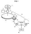
- Fig. 1 is a schematic representation of a steering angular velocity computing device in a preferred embodiment of the present invention.
- steering wheel 1 is operated by a driver of an automobile (not shown).
- Steering wheel 1 is coupled to steering mechanism 3 and first rotating body 11 (hereinafter referred to as “body 11" ) provided on steering angular velocity computing device 10 (hereinafter referred to as “device 10") through steering shaft 2.
- Steering mechanism 3 is coupled to wheel 4 of the automobile and wheel 4 is steered by a rotation transmitted by steering wheel 1.
- Body 11 has first teeth 12 (hereinafter referred to as “teeth 12") on the outer periphery.
- Teeth 12 engage second teeth 14 (hereinafter referred to as “teeth 14") provided on the outer periphery of second rotating body 13 (hereinafter referred to as "body 13").
- Magnet 15 is incorporated in the central part of body 13. So, body 13 and magnet 15 rotate together. Accordingly, magnet 15 rotates at a velocity determined by the ratio of the numbers of teeth of teeth 12 to teeth 14.
- Magnetic steering angle detector 16 (hereinafter referred to as “detector 16") is provided beneath magnet 15 and opposite to magnet 15.
- a magnetic steering angle sensor such as an anisotropic magnetic resistance element (AMR), for example, can be employed as detector 16.
- Detector 16 detects a rotating state of rotating body 13 in association with a change in the steering angle and outputs a stepwise steering angle signal 18 (hereinafter referred to as “signal 18").
- signal 18 is inputted to operating unit 17 composed of a microcomputer and the like. So, operating unit 17 computes angle of rotation and outputs steering angular velocity signal 19 (hereinafter referred to as “signal 19").
- Timer 20 for timing sends information on the measured time to operating unit 17. Also, timer 20 starts timing from zero each time the measured time is reset to zero.
- Fig. 1 when body 11 is rotated by operating steering wheel 1, body 13 is rotated by engagement of teeth 12 and teeth 14. Assuming the number of teeth of teeth 12 and the number of teeth of teeth 14 to be C and D, respectively, the rotating velocity ratio of body 13 to body 11 is C to D. That is, body 13 makes C/D rotations while body 11 makes one rotation. By a proper selection of number of gear teeth C and D, body 13 is rotated faster than body 11. Accordingly, detecting resolution of detector 16 can be enhanced.
- Detector 16 is disposed at a position opposed to magnet 15. Accordingly, when body 13 is rotated, the direction of magnetic force that penetrates detector 16 changes and detector 16 detects a change in the steering angle. Detector 16 outputs the detected change of the steering angle in the form of stepwise signal 18. In other words, a change in the steering angle corresponds to a change in signal 18.
- Timer 20 measures the time required from a time at signal 18 first changed to a time at signal 18 next changed. Signal 18 and the required time are input to operating unit 17, computed, and signal 19 is outputted from operating unit 17.
- Fig. 2 is a flow chart showing the steering angular velocity computing method as employed in steering angular velocity computing device 10 shown in Fig. 1 .
- step S1 when an ignition key (not shown) of an automobile is actuated, device 10 performs initial operation (step S1). During the initial operation, the measured time T n (hereinafter referred to as “time T n ”) of timer 20 and reference time T n-1 are reset to zero. In addition, detected values of steering angular velocity V n (hereinafter referred to as “velocity V n "), reference velocity V n-1 and the number of making extension Y are reset to zero. Timer 20 starts timing after time T n has been reset to zero.
- the "TRUNC" function is defined as a function in which a decimal is cut off. That is, velocity V n is always an integer.
- time T n here represents the required time corresponding to the amount of change X n in the steering angle.
- Velocity V n that is a computed result is outputted from operating unit 17 as signal 19.
- time T n is substituted for reference time T n-1 that is required time for change of immediately preceding signal 18.
- velocity V n is substituted for reference velocity V n-1 that is immediately preceding steering angular velocity (step S4).
- time T n is reset to zero, timing by timer 20 resumes, and the step returns to step S2.
- period T e is a sum of first extended output period (hereinafter referred to as "period")
- T e1 T n-1 ⁇ A obtained by multiplying reference time T n-1 by time coefficient A
- second extended output period hereinafter referred to as "period”
- T e2 T c ⁇ Y obtained by multiplying constant extended period T c by the number of making extension Y.
- step 7 the number of making extension Y in which time T n exceeded period T e is counted up.
- step 7 the number of making extension Y in which time T n exceeded period T e is counted up.
- step S8 velocity V n is substituted with reduced steering angular velocity V n-1 ⁇ B Y obtained by multiplying reference velocity V n-1 by the y-th power of velocity coefficient B and dropping a decimal, and is outputted as output 19 (step S8).
- velocity V n is always an integer. That is, each time the number of making extension Y increases, the rate of reduction of the reduced steering angular velocity decreases exponentially. Subsequently, the step proceeds to step S2, and step S2 and subsequent steps are repeated again.
- step S6 if time T n does not exceed period T e , the step returns to step S2 again, and step S2 and subsequent steps are repeated. As output signal 19, the value of velocity V n is outputted.
- Extended output period T e is first extended for first extended output period T e1 . Furthermore, if no change in the steering angle is yet detected, the time during which velocity V n is outputted is extended for second extended output period T e2 obtained by multiplying constant period T c by the number of making extension Y. Also, each time extended output period T e is extended, velocity V n is reduced.
- the output of velocity V n is gradually reduced even when it is not possible to detect, in the event no change in the steering angle is detected, whether steering angle change has come to a complete standstill or a steering angle change is undergoing at an extremely low velocity. And, finally, the output of velocity V n smoothly comes to a steering angular velocity standstill.
- Fig. 3 is a diagram to show the behavior of signal 18 and signal 19 while the steering angular velocity is being reduced in the steering angular velocity computing device shown in Fig. 1 .
- steering angle 21 represents the behavior of signal 18 when steering velocity is being reduced showing a gradual increase in the required time T (T n-2 ⁇ T n-1 ⁇ T n ⁇ T n+1 ).
- steering angular velocity 23 (hereinafter referred to as “velocity 23”) represents the behavior of signal 19 when steering angular velocity is computed after elapse of reference time T n-1 without extending the time until computation of the next steering angular velocity.
- time coefficient A is not applied to velocity 23, and no change in the steering angle is detected during reference time T n-1 .
- a part is produced during reduction of the steering angular velocity in which velocity 23 is zero as shown in Fig. 3 . That is, velocity 23 partially shows a state of steering angular velocity standstill (0deg/s) thus outputting a discontinuous output.
- Fig. 4 is a diagram showing an example of a steering angular velocity output when steering angular velocity came to a standstill and no change occurred in signal 18 after a prior change in steering angle signal 18.
- Steering angular velocity 25 represents steering angular velocity signal 19 after a change in the steering angle came to a standstill.
- First value of steering angular velocity 26 (hereinafter referred to as “velocity 26") represents velocity 25 when steering angle change is at a standstill.
- Second value of steering angular velocity 27 (hereinafter referred to as “velocity 27”) represents velocity 25 at period T e1 after the steering angle change came to a standstill.
- Period 29 is constant extended period T c and is a period in which steering angular velocity 25 in respective periods is maintained and outputted.
- velocity 26 is outputted after time has been extended by 25%.
- the steering angular velocity becomes zero. This is because the amount of change in the steering angle is zero. At this time, however, it is not possible to determine whether steering angle change has come to a complete standstill or a steering angle change is undergoing at an extremely low velocity.
- velocity 28 is outputted which is reduced steering angular velocity obtained by further multiplying velocity 27 by velocity coefficient B and dropping a decimal.
- extended output period T e is extended in sequence by constant extended period T c .
- velocity 25 is reduced for each period of constant extended period T c thus approaching a state of a steering angular velocity standstill (0 deg/s) with time.
- velocity 25 is outputted in response to actual change in the steering angle.
- Fig. 5 is a diagram showing an example of steering angular velocity until it reaches a state of steering angular velocity standstill by using time coefficient A and velocity coefficient B.
- steering angular velocity 32 (hereinafter referred to as “velocity 32" ) represents the behavior of a change in steering angular velocity signal 19 when the last steering angular velocity was 10 deg/s.
- steering angular velocity 33 (hereinafter referred to as “velocity 33”) represents the behavior of signal 19 when the last steering angular velocity was 5 deg/s.
- time coefficient A and velocity coefficient B are set in a manner selectable depending on the last steering angular velocity.
- time coefficient A 5/4
- velocity coefficient B 3/4
- the required time for the last change in the steering angle is 50ms for velocity 32 and 101ms for velocity 33.
- velocity 32 and velocity 33 come to states of steering angular velocity standstill after elapsed time of 183ms and 198ms, respectively, or in nearly the same time.
- time coefficient A, velocity coefficient B and constant extended period T c are not limited to the above-mentioned values.
- Optimum coefficients may be used at any time depending on the change of the actual steering angular velocity. Furthermore, these coefficients may be properly selected according to the characteristics of body control systems of automobiles and vessels of which a description is omitted.
- a decimal of detected value of steering angular velocity V n is dropped so that it becomes an integer.
- velocity V n is not limited to integers.
- velocity V n may be in units of 0.1 or 0.01.
- the resolution for outputting velocity V n in a step-wise manner may be appropriately chosen depending on the characteristics of detector 16, operating unit 17 and body control system.
Landscapes
- Engineering & Computer Science (AREA)
- Chemical & Material Sciences (AREA)
- Combustion & Propulsion (AREA)
- Transportation (AREA)
- Mechanical Engineering (AREA)
- Physics & Mathematics (AREA)
- General Physics & Mathematics (AREA)
- Steering Control In Accordance With Driving Conditions (AREA)
- Length Measuring Devices With Unspecified Measuring Means (AREA)
Description
- The present invention relates to a steering angular velocity computing device and method for computing steering angular velocity to be used in body control systems of automobiles or vessels.
- As a method for computing steering angular velocity as used in body control systems of automobiles or vessels, a method of moving averages has heretofore been known in which steering angular velocity is computed by the amount of change of the steering angle during a predetermined period of time. Also known is a steering angular velocity computing method in which steering angular velocity is computed by dividing the amount of change of the steering angle during an interval between the moment at which steering angle made a change and the moment at which the steering angle next changed by the interval and maintaining the steering angular velocity during that interval.
- These conventional methods of computing steering angular velocity are disclosed in
Japanese Laid-Open Patent Application No. 2000-85609 claims 1 and 5. - In case that the angular velocity comes to sufficient small values, the time period between successive changes of steering angle becomes larger than a predetermined value Tmax. In this case, an output signal A is generated which represents this situation.
- A steering angular velocity computing device of the present invention has a steering angle detector, a timer and a steering angular velocity computing unit. The steering angle detector detects a change in a steering angle and the timer measures a required time from a time at which the steering angle made a change until a time at which the steering angle next changed. The steering angular velocity computing unit computes, after the detector has detected a change in the steering angle, the steering angular velocity by dividing an amount of change in the steering angle by the required time corresponding to the amount of change and produces it as an output. When the steering angular velocity is being reduced, the steering angular velocity computing unit produces a steering angular velocity output for a first extended output period longer than the required time. With this structure, the steering angular velocity is outputted with good accuracy when the steering angular velocity is being reduced.
-
-
Fig. 1 is a schematic representation of a steering angular velocity computing device in a preferred embodiment of the present invention. -
Fig. 2 is a flow chart of a steering angular velocity computing method as used in the steering angular velocity computing device shown inFig. 1 . -
Fig. 3 is a diagram to illustrate a change in the steering angular velocity during deceleration of the steering angular velocity computing device shown inFig. 1 . -
Fig. 4 is a diagram to illustrate steering angular velocity when the steering angular velocity computing device shown inFig. 1 is in a state of steering angular velocity standstill. -
Fig. 5 is a diagram to illustrate an example of steering angular velocity when the steering angular velocity computing device shown inFig. 1 is in a state of steering angular velocity standstill. -
Fig. 1 is a schematic representation of a steering angular velocity computing device in a preferred embodiment of the present invention. - In
Fig. 1 ,steering wheel 1 is operated by a driver of an automobile (not shown).Steering wheel 1 is coupled tosteering mechanism 3 and first rotating body 11 (hereinafter referred to as "body 11" ) provided on steering angular velocity computing device 10 (hereinafter referred to as "device 10") throughsteering shaft 2.Steering mechanism 3 is coupled towheel 4 of the automobile andwheel 4 is steered by a rotation transmitted bysteering wheel 1.Body 11 has first teeth 12 (hereinafter referred to as "teeth 12") on the outer periphery. Teeth 12 engage second teeth 14 (hereinafter referred to as "teeth 14") provided on the outer periphery of second rotating body 13 (hereinafter referred to as "body 13").Magnet 15 is incorporated in the central part ofbody 13. So,body 13 andmagnet 15 rotate together. Accordingly,magnet 15 rotates at a velocity determined by the ratio of the numbers of teeth ofteeth 12 toteeth 14. - Magnetic steering angle detector 16 (hereinafter referred to as "
detector 16") is provided beneathmagnet 15 and opposite tomagnet 15. A magnetic steering angle sensor such as an anisotropic magnetic resistance element (AMR), for example, can be employed asdetector 16.Detector 16 detects a rotating state of rotatingbody 13 in association with a change in the steering angle and outputs a stepwise steering angle signal 18 (hereinafter referred to as "signal 18"). Furthermore,signal 18 is inputted tooperating unit 17 composed of a microcomputer and the like. So,operating unit 17 computes angle of rotation and outputs steering angular velocity signal 19 (hereinafter referred to as "signal 19").Timer 20 for timing sends information on the measured time to operatingunit 17. Also,timer 20 starts timing from zero each time the measured time is reset to zero. - Now, a description of the action of
device 10 having the above structure will be given in the following. - In
Fig. 1 , whenbody 11 is rotated by operatingsteering wheel 1,body 13 is rotated by engagement ofteeth 12 andteeth 14. Assuming the number of teeth ofteeth 12 and the number of teeth ofteeth 14 to be C and D, respectively, the rotating velocity ratio ofbody 13 tobody 11 is C to D. That is,body 13 makes C/D rotations whilebody 11 makes one rotation. By a proper selection of number of gear teeth C and D,body 13 is rotated faster thanbody 11. Accordingly, detecting resolution ofdetector 16 can be enhanced. -
Detector 16 is disposed at a position opposed tomagnet 15. Accordingly, whenbody 13 is rotated, the direction of magnetic force that penetratesdetector 16 changes anddetector 16 detects a change in the steering angle.Detector 16 outputs the detected change of the steering angle in the form ofstepwise signal 18. In other words, a change in the steering angle corresponds to a change insignal 18.Timer 20 measures the time required from a time atsignal 18 first changed to a time atsignal 18 next changed.Signal 18 and the required time are input tooperating unit 17, computed, andsignal 19 is outputted fromoperating unit 17. - Next, a description will be given on the method of computing steering angular velocity.
-
Fig. 2 is a flow chart showing the steering angular velocity computing method as employed in steering angularvelocity computing device 10 shown inFig. 1 . - In
Fig. 2 , when an ignition key (not shown) of an automobile is actuated,device 10 performs initial operation (step S1). During the initial operation, the measured time Tn (hereinafter referred to as "time Tn") oftimer 20 and reference time Tn-1 are reset to zero. In addition, detected values of steering angular velocity Vn (hereinafter referred to as "velocity Vn"), reference velocity Vn-1 and the number of making extension Y are reset to zero.Timer 20 starts timing after time Tn has been reset to zero. - Subsequently,
device 10 determines whether or notsignal 18 has changed (step S2). Ifsignal 18 has changed, the amount of change Xn in the steering angle is divided by time Tn and velocity Vn = TRUNC(Xn/Tn) is computed (S3). Here, the "TRUNC" function is defined as a function in which a decimal is cut off. That is, velocity Vn is always an integer. Also, time Tn here represents the required time corresponding to the amount of change Xn in the steering angle. Velocity Vn that is a computed result is outputted fromoperating unit 17 assignal 19. - Next, time Tn is substituted for reference time Tn-1 that is required time for change of immediately preceding
signal 18. At the same time, velocity Vn is substituted for reference velocity Vn-1 that is immediately preceding steering angular velocity (step S4). Subsequently, time Tn is reset to zero, timing bytimer 20 resumes, and the step returns to step S2. And,timer 20 measures the required time Tn+1 until occurrence of next change in the steering angle, and next steering angular velocity Vn+1 = TRUNC(Xn+1/Tn+1) is computed by dividing the amount of change of the steering angle Xn+1 in the next change of the steering angle by next required time Tn+1. Step 2 and subsequent steps are repeated in sequence in this way. - On the other hand, when there is no detected a change in
signal 18 in step S2 , determination is made as to whether time Tn exceeds extended output period (hereinafter referred to as "period") Te = Te1 + Te2 = Tn-1×A + Tc×Y (step 6). Here, period Te is a sum of first extended output period (hereinafter referred to as "period") Te1 = Tn-1×A obtained by multiplying reference time Tn-1 by time coefficient A and second extended output period (hereinafter referred to as "period") Te2 = Tc×Y obtained by multiplying constant extended period Tc by the number of making extension Y. - And, if time Tn exceeds period Te, the number of making extension Y in which time Tn exceeded period Te is counted up (step 7). Subsequently, velocity Vn is substituted with reduced steering angular velocity Vn-1×BY obtained by multiplying reference velocity Vn-1 by the y-th power of velocity coefficient B and dropping a decimal, and is outputted as output 19 (step S8). Here, velocity Vn is always an integer. That is, each time the number of making extension Y increases, the rate of reduction of the reduced steering angular velocity decreases exponentially. Subsequently, the step proceeds to step S2, and step S2 and subsequent steps are repeated again.
- Also, in step S6, if time Tn does not exceed period Te, the step returns to step S2 again, and step S2 and subsequent steps are repeated. As
output signal 19, the value of velocity Vn is outputted. - That is, if no change in the steering angle is detected even when reference time Tn-1 has elapsed, the time during which velocity Vn is outputted is extended for extended output period Te. Extended output period Te is first extended for first extended output period Te1. Furthermore, if no change in the steering angle is yet detected, the time during which velocity Vn is outputted is extended for second extended output period Te2 obtained by multiplying constant period Tc by the number of making extension Y. Also, each time extended output period Te is extended, velocity Vn is reduced. Accordingly, the output of velocity Vn is gradually reduced even when it is not possible to detect, in the event no change in the steering angle is detected, whether steering angle change has come to a complete standstill or a steering angle change is undergoing at an extremely low velocity. And, finally, the output of velocity Vn smoothly comes to a steering angular velocity standstill.
-
Fig. 3 is a diagram to show the behavior ofsignal 18 and signal 19 while the steering angular velocity is being reduced in the steering angular velocity computing device shown inFig. 1 . - In
Fig. 3 , steeringangle 21 represents the behavior ofsignal 18 when steering velocity is being reduced showing a gradual increase in the required time T (Tn-2<Tn-1<Tn<Tn+1). Steering angular velocity 22 (hereinafter referred to as "velocity 22") represents the behavior ofsignal 19 when the steering angular velocity is computed by extending the time until computation of next steering angular velocity to period Te1 = Tn-1×A by multiplying by time coefficient A = 5/4 = 1.25. Also, steering angular velocity 23 (hereinafter referred to as "velocity 23") represents the behavior ofsignal 19 when steering angular velocity is computed after elapse of reference time Tn-1 without extending the time until computation of the next steering angular velocity. - In
Fig. 3 , no change in the steering angle is yet detected after reference time Tn-1 has passed. However, as reference time Tn-1 has been extended to period Te1 = Tn-1×A,continuous velocity 22 is computed and outputted based on a change in the steering angle as detected during the extended period. Owing to this, as steering angular velocity Vn will not become apparently zero, it will not come to a standstill. Accordingly,continuous velocity 22 is outputted andvelocity 22 that follows actual change in the steering angular velocity is outputted. - On the other hand, time coefficient A is not applied to
velocity 23, and no change in the steering angle is detected during reference time Tn-1. As a result, a part is produced during reduction of the steering angular velocity in whichvelocity 23 is zero as shown inFig. 3 . That is,velocity 23 partially shows a state of steering angular velocity standstill (0deg/s) thus outputting a discontinuous output. - Also, when the measured steering angular velocity is not changing, it is not possible to detect whether steering angle change has come to a complete standstill or a steering angle change is occuring at an extremely low velocity. As a result, it is not possible to know actual steering angular velocity with good accuracy.
- By extending the apparent length of measuring time by means of time coefficient A as set forth above, no standstill (0 deg/s) of the steering angular velocity occurs during reduction of the steering angular velocity, and
continuous velocity 22 can be outputted. Furthermore, it is possible to outputaccurate velocity 22 that follows actual steering angular velocity. - On the other hand,
Fig. 4 is a diagram showing an example of a steering angular velocity output when steering angular velocity came to a standstill and no change occurred insignal 18 after a prior change insteering angle signal 18. - Steering angular velocity 25 (hereinafter referred to as "
velocity 25") represents steeringangular velocity signal 19 after a change in the steering angle came to a standstill. First value of steering angular velocity 26 (hereinafter referred to as "velocity 26") representsvelocity 25 when steering angle change is at a standstill. Second value of steering angular velocity 27 (hereinafter referred to as "velocity 27") representsvelocity 25 at period Te1 after the steering angle change came to a standstill. Third value of steering angular velocity 28 (hereinafter referred to as "velocity 28") representsvelocity 25 at period Te = Te1 + Te2 = Tn-1×A + Tc×Y, Y being equal to unity, after steering angle change came to a standstill.Period 29 is constant extended period Tc and is a period in which steeringangular velocity 25 in respective periods is maintained and outputted. - In
Fig. 4 , as a change in the steering angle is at a standstill, no change insignal 18 can be detected by nature. Accordingly, it suffices tooutput 0 deg/s asvelocity 25, meaning steering angular velocity is at a standstill. However, it is not possible to determine whether steering angle change has come to a complete standstill or a steering angle change is undergoing at an extremely low velocity. Accordingly, a description will be given onvelocity 25 from a time at last change insignal 18 till standstill of a steering angular velocity change (0 deg/s). -
Velocity 26 as computed last time a change in the steering angle was detected is outputted after computation of velocity Vn only during the period extended to period Te1 = Tn-1×A. As an example, assuming A=5/4,velocity 26 is outputted after time has been extended by 25%. However, as no subsequent change in the steering angle is detected, when steering angular velocity is computed as is, the steering angular velocity becomes zero. This is because the amount of change in the steering angle is zero. At this time, however, it is not possible to determine whether steering angle change has come to a complete standstill or a steering angle change is undergoing at an extremely low velocity. Accordingly, in the event no change in the steering angle is detected after last detection of a change in the steering angle and, in addition, after period Te1 has elapsed,velocity 27 is outputted which is reduced steering angular velocity obtained by multiplying earlier-mentionedvelocity 26 by velocity coefficient B and dropping a decimal. For example, by using a velocity coefficient of B = 3/4 = 0.75, the steering angular velocity is reduced by 25%. - Furthermore, in the event no steering angle change is detected after the output time of
velocity 27 has exceededperiod 29,velocity 28 is outputted which is reduced steering angular velocity obtained by further multiplyingvelocity 27 by velocity coefficient B and dropping a decimal. Thus, when no change in the steering angle is detected, extended output period Te is extended in sequence by constant extended period Tc. And,velocity 25 is reduced for each period of constant extended period Tc thus approaching a state of a steering angular velocity standstill (0 deg/s) with time. - Also, when a change in the steering angle is detected again during the course of gradual reduction of
velocity 25 by using velocity coefficient B, asvelocity 25 increases rapidly,velocity 25 is outputted in response to actual change in the steering angle. - Also,
Fig. 5 is a diagram showing an example of steering angular velocity until it reaches a state of steering angular velocity standstill by using time coefficient A and velocity coefficient B. - In
Fig. 5 , steering angular velocity 32 (hereinafter referred to as "velocity 32" ) represents the behavior of a change in steeringangular velocity signal 19 when the last steering angular velocity was 10 deg/s. Also, steering angular velocity 33 (hereinafter referred to as "velocity 33") represents the behavior ofsignal 19 when the last steering angular velocity was 5 deg/s. - Also, time coefficient A and velocity coefficient B are set in a manner selectable depending on the last steering angular velocity. For
velocity velocity 32 and 101ms forvelocity 33. - Based on the above-mentioned conditions,
velocity 32 andvelocity 33 come to states of steering angular velocity standstill after elapsed time of 183ms and 198ms, respectively, or in nearly the same time. - By the way, time coefficient A, velocity coefficient B and constant extended period Tc are not limited to the above-mentioned values. Optimum coefficients may be used at any time depending on the change of the actual steering angular velocity. Furthermore, these coefficients may be properly selected according to the characteristics of body control systems of automobiles and vessels of which a description is omitted.
- Also, a decimal of detected value of steering angular velocity Vn is dropped so that it becomes an integer. However, velocity Vn is not limited to integers. For example, if there is a margin in the signal processing power, velocity Vn may be in units of 0.1 or 0.01. The resolution for outputting velocity Vn in a step-wise manner may be appropriately chosen depending on the characteristics of
detector 16, operatingunit 17 and body control system.
Claims (5)
- A steering angular velocity computing device comprising:a steering angle detector (16) for detecting stepwise changes in steering angle;a timer (20) for measuring the time period (T) between two successive changes in steering angle, anda steering angular velocity computing unit (17) being adapted to compute the steering angular velocity in time periods between two successive changes in steering angle by dividing the amount of change of the steering angle by the required time period (T) between two successive changes, and outputting consecutive steering angular velocity signals (19),characterized by,
the steering angular velocity computing unit (17) being further adapted to:a) determine when the steering angular velocity decreases, andb) determine the condition that no change in steering angle is detected in a time period (Tn) being extended beyond the last measured time period (Tn-1), andc) then reduce the last computed steering angular velocity signal (19) and output this reduced steering angular velocity signal (vn), wherein
the reduced steering angular velocity signal (19) is obtained by multiplying the steering angular velocity signal by a velocity coefficient (B) in each interval of a constant extended time period (Tc), when a next change in the steering angle is not detected during the extended time period. - The steering angular velocity computing device of claim 1,
wherein the extended time period is obtained by multiplying the required time by a time coefficient (A). - The steering angular velocity computing device of claims 1 or 2, wherein
the steering angle detector (16) is provided with a magnetic steering angle sensor. - The steering angular velocity computing device of claim 3, wherein
the steering angle detector (16) includes:a rotating body (13);a magnet (15) provided in a center of the rotating body; andan anisotropic magnetic resistance element disposed opposite to the magnet. - A steering angular velocity computing method comprising:detecting stepwise changes in steering angle;measuring the time period (T) between two successive changes in steering angle;computing the steering angular velocity by dividing the amount of change of the steering angle by the time period between two successive changes to obtain and output a steering angular velocity signal (19),characterized by,a) determining when the steering angular velocity decreases, andb) determining the condition that no change in steering angle is detected in a time period being extended beyond the last measured time period (T), andc) then reducing the last computed steering angular velocity signal (19) and outputting this reduced steering angular velocity signal (vn), wherein the reduced steering angular velocity signal (19) is obtained by multiplying the steering angular velocity signal by a velocity coefficient (B) in each interval of a constant extended time period (Tc), when a next change in the steering angle is not detected during the extended time period.
Applications Claiming Priority (2)
| Application Number | Priority Date | Filing Date | Title |
|---|---|---|---|
| JP2004021070 | 2004-01-29 | ||
| JP2004021070 | 2004-01-29 |
Publications (3)
| Publication Number | Publication Date |
|---|---|
| EP1559636A2 EP1559636A2 (en) | 2005-08-03 |
| EP1559636A3 EP1559636A3 (en) | 2007-08-15 |
| EP1559636B1 true EP1559636B1 (en) | 2009-02-18 |
Family
ID=34650811
Family Applications (1)
| Application Number | Title | Priority Date | Filing Date |
|---|---|---|---|
| EP05001485A Expired - Lifetime EP1559636B1 (en) | 2004-01-29 | 2005-01-25 | Steering angular velocity computing device and method |
Country Status (4)
| Country | Link |
|---|---|
| US (2) | US7349780B2 (en) |
| EP (1) | EP1559636B1 (en) |
| CN (1) | CN100383530C (en) |
| DE (1) | DE602005012743D1 (en) |
Families Citing this family (6)
| Publication number | Priority date | Publication date | Assignee | Title |
|---|---|---|---|---|
| KR20090073057A (en) * | 2006-05-24 | 2009-07-02 | 티티 일렉트로닉스 테크놀러지 리미티드 | Multiple Turn Rotation Sensor |
| DE602006014553D1 (en) * | 2006-11-08 | 2010-07-08 | Ford Global Tech Llc | Anti-roll control and reduction of tipping over by steering operation |
| JP4987448B2 (en) * | 2006-12-05 | 2012-07-25 | 東芝機械株式会社 | Speed detection device |
| CN105823899B (en) * | 2015-09-16 | 2019-01-11 | 浙江吉利汽车有限公司 | The implementation method of vehicle turning speed is calculated based on rotary transformer |
| CN110989693A (en) * | 2019-12-17 | 2020-04-10 | 深圳市云顶信息技术有限公司 | A swinging device, electric equipment and control method |
| EP3916398B1 (en) * | 2020-05-29 | 2023-10-18 | Honda Motor Co., Ltd. | Crank angular velocity measuring device and misfire detection device |
Family Cites Families (6)
| Publication number | Priority date | Publication date | Assignee | Title |
|---|---|---|---|---|
| DE2839121A1 (en) * | 1978-09-08 | 1980-03-27 | Bosch Gmbh Robert | ELECTRO-HYDRAULIC POWER STEERING |
| US4959806A (en) * | 1988-10-24 | 1990-09-25 | Eaton Corporation | Approximated rotational speed signal for shifting transmission |
| CN1205773A (en) * | 1995-11-20 | 1999-01-20 | 轨道工程有限公司 | Position and Speed Electronic Sensors |
| JP2000085609A (en) * | 1998-09-16 | 2000-03-28 | Koyo Seiko Co Ltd | Steering angular speed detecting device and power steering device using it |
| JP2002213944A (en) * | 2001-01-18 | 2002-07-31 | Niles Parts Co Ltd | Instrument for measuring rotational angle |
| JP3611116B2 (en) * | 2001-10-10 | 2005-01-19 | 三菱電機株式会社 | Electric power steering control device |
-
2005
- 2005-01-25 EP EP05001485A patent/EP1559636B1/en not_active Expired - Lifetime
- 2005-01-25 DE DE602005012743T patent/DE602005012743D1/en not_active Expired - Lifetime
- 2005-01-26 US US11/042,149 patent/US7349780B2/en not_active Expired - Fee Related
- 2005-01-31 CN CNB2005100070471A patent/CN100383530C/en not_active Expired - Fee Related
-
2007
- 2007-10-31 US US11/980,383 patent/US20080071445A1/en not_active Abandoned
Also Published As
| Publication number | Publication date |
|---|---|
| DE602005012743D1 (en) | 2009-04-02 |
| US7349780B2 (en) | 2008-03-25 |
| CN100383530C (en) | 2008-04-23 |
| US20050171666A1 (en) | 2005-08-04 |
| EP1559636A3 (en) | 2007-08-15 |
| CN1648672A (en) | 2005-08-03 |
| EP1559636A2 (en) | 2005-08-03 |
| US20080071445A1 (en) | 2008-03-20 |
Similar Documents
| Publication | Publication Date | Title |
|---|---|---|
| US4856607A (en) | Apparatus for automatically setting steering center for use in power steering apparatus | |
| US4794536A (en) | Steering angle detection device | |
| US7028804B2 (en) | Steering angle neutral position detection error protecting method and detection error protecting apparatus | |
| US4611199A (en) | Alarm system and method for sensing a stand-by state in a driver drowsiness detection system | |
| EP0872406A2 (en) | Method and apparatus for damping control of an electric assist steering system with vehicle speed signal loss feature | |
| US20080071445A1 (en) | Steering angular velocity computing device and method | |
| JPH0665550B2 (en) | Power steering control device | |
| US20010053952A1 (en) | Diagnostic apparatus and method for motor driven power-assisted steering system | |
| EP1316493B1 (en) | Electrically-powered steering apparatus | |
| US6644433B2 (en) | Control apparatus for controlling an electric power steering mechanism | |
| EP1621445B1 (en) | Electric power steering apparatus | |
| US5283741A (en) | Control apparatus for a vehicle power steering system | |
| US5146202A (en) | Vehicular steering condition detecting apparatus | |
| JPH10159964A (en) | Automatic transmission | |
| JP2005241634A (en) | Rudder angular velocity calculation device and rudder angular velocity calculation method | |
| US5400268A (en) | Vehicle speed determining device having means for accurate determination of zeroing of vehicle speed | |
| JP4449201B2 (en) | Steering torque estimation device, steering torque estimation method, and steering device | |
| JP5054644B2 (en) | Vehicle steering control device | |
| EP1403646B1 (en) | Vehicle rapid deceleration detection device | |
| JP2001301638A (en) | Vehicle steering system | |
| JP2943628B2 (en) | Vehicle speed control unit | |
| JPS6345521A (en) | Torque detecting device for output shaft for vehicle | |
| JP2004212179A (en) | Rotational angle detector | |
| JPH10185736A (en) | Reference torque calibration device for torque sensor and steering device using the same | |
| JP3198690B2 (en) | Speed detector for rotating body |
Legal Events
| Date | Code | Title | Description |
|---|---|---|---|
| PUAI | Public reference made under article 153(3) epc to a published international application that has entered the european phase |
Free format text: ORIGINAL CODE: 0009012 |
|
| AK | Designated contracting states |
Kind code of ref document: A2 Designated state(s): AT BE BG CH CY CZ DE DK EE ES FI FR GB GR HU IE IS IT LI LT LU MC NL PL PT RO SE SI SK TR |
|
| AX | Request for extension of the european patent |
Extension state: AL BA HR LV MK YU |
|
| PUAL | Search report despatched |
Free format text: ORIGINAL CODE: 0009013 |
|
| AK | Designated contracting states |
Kind code of ref document: A3 Designated state(s): AT BE BG CH CY CZ DE DK EE ES FI FR GB GR HU IE IS IT LI LT LU MC NL PL PT RO SE SI SK TR |
|
| AX | Request for extension of the european patent |
Extension state: AL BA HR LV MK YU |
|
| 17P | Request for examination filed |
Effective date: 20070829 |
|
| 17Q | First examination report despatched |
Effective date: 20071022 |
|
| AKX | Designation fees paid |
Designated state(s): DE FR GB |
|
| GRAP | Despatch of communication of intention to grant a patent |
Free format text: ORIGINAL CODE: EPIDOSNIGR1 |
|
| RAP1 | Party data changed (applicant data changed or rights of an application transferred) |
Owner name: PANASONIC CORPORATION |
|
| GRAS | Grant fee paid |
Free format text: ORIGINAL CODE: EPIDOSNIGR3 |
|
| GRAA | (expected) grant |
Free format text: ORIGINAL CODE: 0009210 |
|
| AK | Designated contracting states |
Kind code of ref document: B1 Designated state(s): DE FR GB |
|
| REG | Reference to a national code |
Ref country code: GB Ref legal event code: FG4D |
|
| REF | Corresponds to: |
Ref document number: 602005012743 Country of ref document: DE Date of ref document: 20090402 Kind code of ref document: P |
|
| PLBE | No opposition filed within time limit |
Free format text: ORIGINAL CODE: 0009261 |
|
| STAA | Information on the status of an ep patent application or granted ep patent |
Free format text: STATUS: NO OPPOSITION FILED WITHIN TIME LIMIT |
|
| 26N | No opposition filed |
Effective date: 20091119 |
|
| PGFP | Annual fee paid to national office [announced via postgrant information from national office to epo] |
Ref country code: FR Payment date: 20100208 Year of fee payment: 6 |
|
| PGFP | Annual fee paid to national office [announced via postgrant information from national office to epo] |
Ref country code: DE Payment date: 20100121 Year of fee payment: 6 |
|
| REG | Reference to a national code |
Ref country code: FR Ref legal event code: ST Effective date: 20110930 |
|
| PG25 | Lapsed in a contracting state [announced via postgrant information from national office to epo] |
Ref country code: FR Free format text: LAPSE BECAUSE OF NON-PAYMENT OF DUE FEES Effective date: 20110131 |
|
| REG | Reference to a national code |
Ref country code: DE Ref legal event code: R119 Ref document number: 602005012743 Country of ref document: DE Effective date: 20110802 |
|
| PGFP | Annual fee paid to national office [announced via postgrant information from national office to epo] |
Ref country code: GB Payment date: 20130123 Year of fee payment: 9 |
|
| PG25 | Lapsed in a contracting state [announced via postgrant information from national office to epo] |
Ref country code: DE Free format text: LAPSE BECAUSE OF NON-PAYMENT OF DUE FEES Effective date: 20110802 |
|
| GBPC | Gb: european patent ceased through non-payment of renewal fee |
Effective date: 20140125 |
|
| PG25 | Lapsed in a contracting state [announced via postgrant information from national office to epo] |
Ref country code: GB Free format text: LAPSE BECAUSE OF NON-PAYMENT OF DUE FEES Effective date: 20140125 |