EP1559588A1 - Radial tire with circumferential spirally wound belt layer - Google Patents
Radial tire with circumferential spirally wound belt layer Download PDFInfo
- Publication number
- EP1559588A1 EP1559588A1 EP03810676A EP03810676A EP1559588A1 EP 1559588 A1 EP1559588 A1 EP 1559588A1 EP 03810676 A EP03810676 A EP 03810676A EP 03810676 A EP03810676 A EP 03810676A EP 1559588 A1 EP1559588 A1 EP 1559588A1
- Authority
- EP
- European Patent Office
- Prior art keywords
- code
- belt
- belt layer
- spirally wound
- oblique
- Prior art date
- Legal status (The legal status is an assumption and is not a legal conclusion. Google has not performed a legal analysis and makes no representation as to the accuracy of the status listed.)
- Granted
Links
Images


Classifications
-
- B—PERFORMING OPERATIONS; TRANSPORTING
- B60—VEHICLES IN GENERAL
- B60C—VEHICLE TYRES; TYRE INFLATION; TYRE CHANGING; CONNECTING VALVES TO INFLATABLE ELASTIC BODIES IN GENERAL; DEVICES OR ARRANGEMENTS RELATED TO TYRES
- B60C9/00—Reinforcements or ply arrangement of pneumatic tyres
- B60C9/18—Structure or arrangement of belts or breakers, crown-reinforcing or cushioning layers
- B60C9/20—Structure or arrangement of belts or breakers, crown-reinforcing or cushioning layers built-up from rubberised plies each having all cords arranged substantially parallel
- B60C9/22—Structure or arrangement of belts or breakers, crown-reinforcing or cushioning layers built-up from rubberised plies each having all cords arranged substantially parallel the plies being arranged with all cords disposed along the circumference of the tyre
- B60C9/2204—Structure or arrangement of belts or breakers, crown-reinforcing or cushioning layers built-up from rubberised plies each having all cords arranged substantially parallel the plies being arranged with all cords disposed along the circumference of the tyre obtained by circumferentially narrow strip winding
-
- B—PERFORMING OPERATIONS; TRANSPORTING
- B60—VEHICLES IN GENERAL
- B60C—VEHICLE TYRES; TYRE INFLATION; TYRE CHANGING; CONNECTING VALVES TO INFLATABLE ELASTIC BODIES IN GENERAL; DEVICES OR ARRANGEMENTS RELATED TO TYRES
- B60C9/00—Reinforcements or ply arrangement of pneumatic tyres
-
- B—PERFORMING OPERATIONS; TRANSPORTING
- B60—VEHICLES IN GENERAL
- B60C—VEHICLE TYRES; TYRE INFLATION; TYRE CHANGING; CONNECTING VALVES TO INFLATABLE ELASTIC BODIES IN GENERAL; DEVICES OR ARRANGEMENTS RELATED TO TYRES
- B60C9/00—Reinforcements or ply arrangement of pneumatic tyres
- B60C9/0007—Reinforcements made of metallic elements, e.g. cords, yarns, filaments or fibres made from metal
-
- B—PERFORMING OPERATIONS; TRANSPORTING
- B60—VEHICLES IN GENERAL
- B60C—VEHICLE TYRES; TYRE INFLATION; TYRE CHANGING; CONNECTING VALVES TO INFLATABLE ELASTIC BODIES IN GENERAL; DEVICES OR ARRANGEMENTS RELATED TO TYRES
- B60C9/00—Reinforcements or ply arrangement of pneumatic tyres
- B60C9/0042—Reinforcements made of synthetic materials
-
- B—PERFORMING OPERATIONS; TRANSPORTING
- B60—VEHICLES IN GENERAL
- B60C—VEHICLE TYRES; TYRE INFLATION; TYRE CHANGING; CONNECTING VALVES TO INFLATABLE ELASTIC BODIES IN GENERAL; DEVICES OR ARRANGEMENTS RELATED TO TYRES
- B60C9/00—Reinforcements or ply arrangement of pneumatic tyres
- B60C9/005—Reinforcements made of different materials, e.g. hybrid or composite cords
-
- D—TEXTILES; PAPER
- D02—YARNS; MECHANICAL FINISHING OF YARNS OR ROPES; WARPING OR BEAMING
- D02G—CRIMPING OR CURLING FIBRES, FILAMENTS, THREADS, OR YARNS; YARNS OR THREADS
- D02G3/00—Yarns or threads, e.g. fancy yarns; Processes or apparatus for the production thereof, not otherwise provided for
- D02G3/44—Yarns or threads characterised by the purpose for which they are designed
- D02G3/48—Tyre cords
-
- D—TEXTILES; PAPER
- D10—INDEXING SCHEME ASSOCIATED WITH SUBLASSES OF SECTION D, RELATING TO TEXTILES
- D10B—INDEXING SCHEME ASSOCIATED WITH SUBLASSES OF SECTION D, RELATING TO TEXTILES
- D10B2331/00—Fibres made from polymers obtained otherwise than by reactions only involving carbon-to-carbon unsaturated bonds, e.g. polycondensation products
- D10B2331/02—Fibres made from polymers obtained otherwise than by reactions only involving carbon-to-carbon unsaturated bonds, e.g. polycondensation products polyamides
- D10B2331/021—Fibres made from polymers obtained otherwise than by reactions only involving carbon-to-carbon unsaturated bonds, e.g. polycondensation products polyamides aromatic polyamides, e.g. aramides
-
- Y—GENERAL TAGGING OF NEW TECHNOLOGICAL DEVELOPMENTS; GENERAL TAGGING OF CROSS-SECTIONAL TECHNOLOGIES SPANNING OVER SEVERAL SECTIONS OF THE IPC; TECHNICAL SUBJECTS COVERED BY FORMER USPC CROSS-REFERENCE ART COLLECTIONS [XRACs] AND DIGESTS
- Y10—TECHNICAL SUBJECTS COVERED BY FORMER USPC
- Y10T—TECHNICAL SUBJECTS COVERED BY FORMER US CLASSIFICATION
- Y10T152/00—Resilient tires and wheels
- Y10T152/10—Tires, resilient
- Y10T152/10495—Pneumatic tire or inner tube
- Y10T152/10765—Characterized by belt or breaker structure
- Y10T152/10783—Reinforcing plies made up from wound narrow ribbons
Definitions
- the present invention relates to a radial tire having belt codes of a belt layer which are arranged to be spirally wound almost in parallel with a tire circumferential direction.
- body ply codes which extend from a tread section to each sidewall section to be turned up over a bead core of a bead section are arranged in a radial code fashion (arrangement at an angle in the range of 85 to 90 degrees relative to the tire circumferential direction), a secondary belt layer in which steel codes are inclined at an angle in the range of 20 to 40 degrees relative to the tire circumferential direction is arranged as a single layer over an outer circumference for a tread section of the body ply in the tire circumferential direction, and a steel code or an organic fiber code such as Kevlar® which is large in the increase rate of tensile load to stretch rate is spirally wound on an outer circumference side of the oblique belt layer almost in parallel with the tire circumferential direction to form a main belt layer.
- the belt layers are to prevent the movement of the body ply by a so-called "hoop effect" which suppress the radial expansion of the body ply for securing the steering stability, high-speed endurance and wear resistance which are characteristic performances of radial tires.
- belt codes arranged in the belt layers there have been used steel codes and aromatic polyamide fibers which are large in the increase rate of tensile road to stretch rate for a greater "hoop effect".
- the green tire In vulcanizing a so-called "green tire” formed with unvulcanized compounded rubber in a manufacturing process of tires, the green tire is put in a mold and is vulcanized and formed in the mold with heat and pressure being applied inside. To obtain a target tire shape by the vulcanization and forming, the green tire is expanded within the mold to add a stretch of several percents or, in dependence upon the type of the forming method, 0.5 to 3 %.
- the present invention is made to solve the aforementioned problems and is to provide a radial tire with a belt layer in which there is circumferentially spirally wound a belt code capable of allowing the green tire to expand with a correct shape retained during a vulcanizing and forming process and also capable of exercising a sufficient hoop effect after the vulcanizing and forming process.
- a first invention resides in a radial tire provided with a body ply extending from a tread section to sidewall sections and having at both side ends thereof turned-up portions which are turned up over bead cores of bead sections; a belt layer wound on an outer circumference of the body ply in a tire circumferential direction; a tread circumferentially arranged on an outer circumference of the belt layer; and bead fillers extending from the bead cores radially outward between the sidewall sections and the turned-up portions of the body ply, wherein the belt layer comprises at least one spirally wound belt layer in which one or plural belt codes coated with rubber are arranged to be spirally wound almost in parallel with the tire circumferential direction; and wherein the belt code in the spirally wound belt layer is small in the increase rate of tensile load to stretch rate in the range of a predetermined stretch rate or less but is larger in the increase rate of tensile load in a range exceeding the predetermined stretch rate.
- the belt code is expanded under a small tensile load not to prevent body ply codes from expanding, a green tire is vulcanized and formed with respective parts thereof being adhered as a result of being expanded to keep a regular shape.
- the tire is vulcanized and formed with the belt code being expanded by the predetermined stretch rate and after the vulcanization, becomes large in the increase rate of tensile road to stretch rate to exercise a sufficient hoop effect.
- the tire can be well maintained in a desired toroidal shape, can be increased in a forward-rearward rigidity in the tire circumferential direction, can suppress the movement of the treading surface, can be enhanced in the braking performance to avoid collisional accident, and further can make the shape of a ground contact surface on the treading surface proper. As a consequence, it becomes possible to make sudden starting and sharp steering as well as to enhance steering stability.
- a second invention resides in a radial tire with the circumferentially spirally wound belt layer according to the aforementioned first invention, wherein the belt code in the spirally wound belt layer is of the property that the stretch rate is equal to or greater than 0.5 % at the tensile load of 20 N and that the tensile load at the stretch rate of 3 % is equal to or greater than 60 N (preferably, the tensile load at the stretch rate of 1.5 % is equal to or greater than 30 N).
- the tire when the diameter of the green tire is expanded at an expansion rate in the rage of 0.5 to 3 %, the tire is vulcanized and formed with respective parts thereof being adhered as a result of having the entire shape thereof maintained properly and after the vulcanization and forming, becomes large in the hoop effect that the belt layer suppresses the expansion of the body ply.
- a third invention resides in a radial tire with the circumferentially spirally wound belt layer according to the aforementioned first or second invention, wherein the belt code in the spirally wound belt layer is made of a hybrid code having a nylon fiber bundle as a core and having an aramid fiber bundle twisted therearound.
- the present invention can be realized to provide a light belt code having a property that the increase rate of tensile load to stretch rate is small in the range of a predetermined stretch rate or less, but is large in the increase rate of tensile load in a range exceeding the predetermined stretch rate.
- a fourth invention resides in a radial tire with the circumferentially spirally wound belt layer according to the aforementioned first or second invention, wherein the belt code in the spirally wound belt layer is made of a multi-strand steel code which is made by twisting plural steel strands.
- the present invention can be realized to provide a belt code which is small in the increase rate of tensile load to stretch rate in the range of a predetermined stretch rate or less, but abruptly increases the increase rate of tensile load in a range exceeding the predetermined stretch rate to have a large hoop effect.
- a fifth invention resides in a radial tire with the circumferentially spirally wound belt layer according to the aforementioned first or second invention, wherein the belt code in the spirally wound belt layer is made of a waved steel code which is made by giving a waving processing to a steel code which is made by twisting plural steel filaments.
- the present invention it can be realized to easily adjust the property of the steel belt code which is large in the hoop effect as being small in the increase rate of tensile load to stretch rate in the range of a predetermined stretch rate or less, but abruptly increasing the increase rate of tensile load in a range exceeding the predetermined stretch rate.
- a sixth invention resides in a radial tire with the circumferentially spirally wound belt layer according to any one of the aforementioned first to fifth inventions, wherein the body ply is arranged to be at least one layer; wherein body ply codes in the body ply are inclined at an angle in the range of 85 to 90 degrees relative to the circumferential direction; and wherein the belt layer arranged on the outer circumference of the body ply comprises an oblique belt layer in which a belt code made of steel is arranged as one layer to be inclined at an angle in the range of 10 to 40 degrees relative to the circumferential direction and at least one spirally wound belt layer in which a belt code is spirally arranged on an outer circumference of the oblique belt layer almost in parallel with the tire circumferential direction.
- the present invention in addition to the effects of the first invention, it can be realized to lighten the radial tire, to enhance the braking performance and the steering stability of the tire and to maintain the high-speed endurance and the wear resistance.
- a seventh invention resides in a radial tire with the circumferentially spirally wound belt layer according to any one of the aforementioned first to third inventions, wherein the body ply is arranged to be at least one layer; wherein body ply codes in the body ply are inclined at an angle in the range of 85 to 90 degrees relative to the circumferential direction; and wherein the belt layer arranged on the outer circumference of the body ply comprises two oblique belt layers in which belt codes made of steel are arranged to be inclined in the same direction at the same angle in the range of 30 to 60 degrees (preferably, in the range of 40 to 50 degrees) relative to the circumferential direction and at least one spirally wound belt layer in which a rubber-coated belt code made of a hybrid code is spirally arranged on outer circumferences of the oblique belt layers almost in parallel with the tire circumferential direction; and wherein of the two oblique belt layers, one oblique belt layer is in the range of 40 to 70 % of the other ob
- the present invention by the hoop effects of the two belt layers inclined in the same direction and the circumferentially spirally wound belt layer, it can be realized to enhance the braking performance, the steering stability and the wear resistance of the tire and in particular, to enhance the braking effect on wet roads.
- two belt layers are arranged to have respective belt codes wound and inclined in opposite directions and crossed mutually. In that case, respective belt codes interfere to be twisted, and this causes the distribution of the ground contact pressure on the ground contact surface to be uneven and not to become flat, so that though the ground contact area appears unchanged, there is decreased a substantial ground contact area which works for the braking performance and the steering stability.
- the two oblique belt layers are wound with the belt codes being inclined at the same angle in the same direction, the distribution of the ground contact pressure on the ground contact surface becomes even and flat, so that though the ground contact area appears unchanged, the substantial ground contact area which works for the braking performance and the steering stability can be made to be large thereby to improve the braking performance and the steering stability.
- one oblique belt layer of the two oblique belt layers is in the range of 40 to 70 % of the other oblique belt layer in width and is circumferentially arranged at the center portion in the direction of the radial tire width, the floating motion which is liable to occur at the center portion of the tread surface when a sudden increase in load is brought about upon braking can be suppressed, and the flexibility of the tread section can be maintained.
- An eighth invention resides in a radial tire with the circumferentially spirally wound belt layer according to the aforementioned seventh invention, wherein an organic fiber code made of a hybrid code is coated with rubber and is arranged to be spirally wound between the oblique belt layers and the outer circumference of the body ply almost in parallel with the circumferential direction thereby to form a ply under the oblique belt layers; and wherein the arrangement of the organic codes in the ply under the oblique belt layers is made to be densified at shoulder portions on the side edges in the direction of the radial tire width and is made to be loose at the center portion.
- the ply under the oblique belt layers is arranged on the outer circumference of the body ply to extend from the shoulder portions to the center portion, and thus, when a sudden load acts upon braking, the ply under the oblique belt layers suppresses the separations between the body ply codes, so that differences in tension among the body ply codes can be lessened to enhance the braking performance.
- the code in the ply under the oblique belt layers is arranged to be densified at the shoulder portions and to be loose at the center portion, and thus, when an inside pressure is applied to the tire, the ground contact state of the shoulder portions can be kept stable because of the densified arrangement of the organic fiber code thereat, so that it can be realized to remarkably enhance the steering stability and the braking performance of the tire on wet roads and also to enhance the braking performance and the wear resistance on dry roads.
- the organic fiber code is arranged to be loose, so that the separations between the body ply codes can be suppressed without deteriorating the flexibility.
- a ninth invention resides in a radial tire with the circumferentially spirally wound belt layer according to the aforementioned seventh invention, wherein a ply under the oblique belt layers is composed of a waved steel code coated with rubber and arranged to be spirally wound and to be densified between the oblique belt layers and the outer circumference of the body ply at shoulder portions on the side edges in the direction of the radial tire width almost in parallel with the circumferential direction and an organic fiber code made of a hybrid code coated with rubber and arranged to be spirally wound and to be loose between the oblique belt layers and the outer circumference of the body ply at the center portion almost in parallel with the circumferential direction.
- the ply under the oblique belt layers suppresses the separations between the body ply codes, so that differences in tension among the body ply codes can be lessened to enhance the braking performance.
- the waved steel code is employed as the material at the shoulder portions of the ply under the oblique belt layers, the shoulder portions of the radial tire are increased in rigidity and further are stabilized in the ground contact state upon sudden braking.
- remarkable improvements can be made in the braking performance and the steering stability of the tire on wet roads, and improvements can also be made in the braking performance and the wear resistance on dry roads.
- the organic fiber code spirally wound to be loose the floating of the center portion can be suppressed to the extent that the flexibility cannot be deteriorated.
- a tenth invention resides in a radial tire with the circumferentially wound belt layer according to the aforementioned seventh invention, wherein a code which is small in the increase rate of tensile load to stretch rate in the range of a predetermined stretch rate or less but is large in the increase rate of tensile load in a range exceeding the predetermined stretch rate is coated with rubber and is arranged to be spirally wound between the oblique belt layers and the outer circumference of the body ply almost in parallel with the circumferential direction thereby to form a ply under the oblique belt layers, and wherein the code in the ply under the oblique belt layers is arranged to be densified at the shoulder portions on the side edges in the direction of the radial tire width and at the center portion, but to be loose at a portion between each shoulder portion and the center portion.
- the ply under the oblique belt layers is arranged on the outer circumference of the body ply to extend from the shoulder portions to the center portion, and thus, when a sudden load acts upon braking, the ply under the oblique belt layers suppresses the separations between the body ply codes, so that differences in tension among the body ply codes can be lessened to enhance the braking performance.
- the code in the ply under the oblique belt layers is arranged to be densified at the shoulder portions and the center portion and to be loose at the portion between each shoulder portion and the center portion, the loose portion serves for lightening the tire, and at the same time, the ground contact state is kept to be always stable at the shoulder portions and the center portion where the code arrangement is densified.
- remarkable improvements can be made in the steering stability and the braking performance of the tire on wet roads, and improvements can also be made in the braking performance and the wear resistance on dry roads. Because of being densified at the center portion, the floating of the center portion in high speed traveling can be suppressed to improve the steering stability in high speed traveling.
- An eleventh invention resides in a radial tire with the circumferentially spirally wound belt layer according to the aforementioned tenth invention, wherein a code which is small in the increase rate of tensile load to stretch rate in the range of a predetermined stretch rate or less but is large in the increase rate of tensile load in a range exceeding the predetermined stretch rate is coated with rubber and is arranged to be spirally wound between the spirally wound belt layer and the oblique belt layers almost in parallel with the circumferential direction thereby to form a ply under the spirally wound belt layer, and wherein the code in the ply under the spirally wound belt layer is arranged to be densified at the shoulder portions on the side edges in the direction of the radial tire width and at the center portion, but to be loose at the portion between each shoulder portion and the center portion.
- the ply under the oblique belt layers suppresses the separations between the body ply codes, so that differences in tension among the body ply codes can be lessened to enhance the braking performance.
- the shoulder portions and the center portion are heightened in rigidity, and the ground contact state at the shoulder portions upon sudden braking is stabilized.
- remarkable improvements can be made in the braking performance and the steering stability of the tire on wet roads, and improvements can also be made in the braking performance and the wear resistance on dry roads.
- the floating of the center portion in high speed traveling can be suppressed to improve the steering stability in high speed traveling.
- the ply under the spirally wound belt layer is arranged between the circumferentially spirally wound belt layer and the oblique belt layers, the hoop effect on the body ply can further be strengthened thereby to improve the steering stability and the wear resistance.
- the steel codes in the oblique belt layers are sandwiched and tied by the ply under the spirally wound belt layer and the ply under the oblique belt layers to be densified at the shoulder portions and the center portion, the movement of the steel codes in the oblique belt layers is restricted during the rolling of the tire, whereby reduction can be made in the noise in the car on rough roads.
- a twelfth invention resides in a radial tire with the circumferentially spirally wound belt layer according to any one of the aforementioned sixth to eleventh inventions, wherein both side portions of the spirally wound belt layer cover both side portions of the oblique belt layers.
- Figure 1 is a sectional view of a radial tire, taken in a tire radial direction, having circumferentially spirally wound belt layers in a first embodiment
- Figure 2 is a figure showing a body ply and the belt layers in the first embodiment
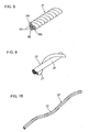
- Figure 3 is a figure showing the states of a belt code and belt codes coated with unvulcanized compounded rubber
- Figure 4 is a graph showing tensile loads of belt codes relative to stretch rates
- Figure 5 is a perspective view of a multi-strand steel code
- Figure 6 is a sectional view of a radial tire, taken in a tire radial direction, having circumferentially spirally wound belt layers in a second embodiment
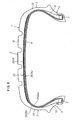
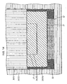
- Figure 7 is a figure showing body plies and the belt layers in the second embodiment
- Figure 8 is a perspective view of a hybrid code
- Figure 9 is a sectional view of a radial tire, taken in a tire radial direction, having circumferentially spirally wound belt layers in a third embodiment
- the radial tire 1 is composed of a tread section 2, sidewall sections 3 at both sides of the tire radially bent from both sides of the tread section 2 toward the tire axis, and annular bead sections 4 constituting inner circumferences of the respective sidewall sections 3.
- the bead sections 4 at the both sides are provided with bead cores 5 each constituted by annually winding a steel code.
- a body ply 6 extends from the tread section 2 to pass through the sidewall sections 3 at the both sides and then to be turned up over the respective bead cores 5, so that the body play 6 is suspended between the both side beads.
- body ply codes 7 are coated with rubber and are arranged at an oblique angel in the range of 85 to 90 degrees relative to the tire circumferential direction.
- the spirally wound belt layer 10 comprising two layers 9a and 9b is formed on the outer circumference of the body ply 6, and in each of the layers, a belt code 9 having an appropriate tensile rigidity is coated with rubber and is spirally wound at an oblique angle in the range of 0 to 9 degrees almost in parallel with the tire circumferential direction.
- the spirally wound belt layer 10 may be formed by spirally winding a single belt code 9 in turn for the first layer 9a and the second layer 9b with the circumferential surface of the belt code 9 coated with unvulcanized compounded rubber as shown in Figure 3(a).
- the spirally wound belt layer 10 may be constituted by spirally winding plural belt codes simultaneously in turn for the first layer 9a and the second layer 9b with the plural belt codes coated with unvulcanized compounded rubber in a parallel arrangement to form a ribbon as shown in Figure 3(b).
- the spirally wound belt layer 10 may be constituted by spirally winding, by one turn, plural belt codes of double layers which are coated with unvulcanized compounded rubber in parallel arrangements with one layer for the first layer 9a piled up on the other layer for the second layer 9b as shown in Figure 3(c).
- a manufacturing method of spirally winding the rubber-coated belt codes 9 on the outer circumference of the body ply 6 can be implemented by a known method described in, e.g., Japanese unexamined, published patent application No. 2002-137607 and is therefore omitted from being described.
- the belt codes 9 are spirally wound to form two layers almost in parallel with the tire circumferential direction with the increase rate of tensile load to stretch rate kept to be large.
- the hoop effect that the spirally wound belt layer 10 prevents the body ply 6 from expanding becomes large to keep the tire properly in a desired toroidal shape, and the forward-rearward rigidity in the tire circumferential direction can be increased to suppress the displacement of the tread surface, so that the braking performance can be enhanced to prevent collisional accidents.
- the steering stability can be improved since sudden starting and sharp steering become possible.
- An inner liner 11 is arranged on the internal surface of the body ply 6, a tread 12 is wound on the outer surface of the spirally wound belt layers 10, a bead filler 13 is arranged between each sidewall section and each turned-up portion of the body ply 6 to extend from each bead core 5 radially outward of the tire, and a side tread 20 is arranged at each of the sidewall section 3.
- a green tire whose structure roughly described above is formed with unvulcanized compounded rubber is put into a vulcanizing mold, and then, an expansible shape fit in the internal surface of the inner liner 11 is expanded while they are heated up to about 200 degrees centigrade, whereby the inner liner 11, the body ply 6, the spirally wound belt layers 10 and the tread 12 are adhered and formed together through the vulcanization of the unvulcanized compounded rubber.
- the expansion of the expansible shape causes the tire outer diameter to expand at an expansion rate in the range of 0.5 to 3 %, and therefore, unless the belt codes 9 can be expanded under a small tensile load during this expansion process, the correct tire shape cannot be kept as a result that the body ply codes 7 are prevented by the unexpanded belt codes 9 from being expanded.
- the tire is vulcanized and formed with the belt code 9 being stretched at a stretch rate in the range of 0.5 to 3 %, the vulcanized and formed tire is heightened in the tensile rigidity of the belt code 9 and is increased in the hoop effect that the spirally wound belt layer 10 prevents the body ply 6 from expanding.
- the tire can be kept properly in a desired toroidal shape, so that improvements can be made in the braking performance and the steering stability.
- the belt code 9 used as one example in the first embodiment was a steel code with a structure of 3 x 3 x 0.175.
- This is a multi-strand steel code 19 having a code diameter of 0.81 ⁇ mm (millimeter) which code is structured by twisting three steel filaments 18a of the diameter 0.175 ⁇ mm to make a strand 18b and then by twisting three strands 18b so made at a short pitch.
- the property of the tensile load relative to the stretch rate of the multi-strand steel code 19 indicates the stretch rate of 0.6 % larger than 0.5 % at the tensile load of 20 N, attains the tensile load of 350 N at the stretch rate of 1.5 %.
- the increase rate of tensile load to stretch rate becomes small, but becomes large as the stretch rate exceeds the predetermined value.
- the belt code 9 used in the spirally wound belt layer 10 may be a waved steel code 50 shown in Figure 15.
- This waved steel code 50 is made by waving a steel code with the structure of 1 x 3 x 0.27 (i.e., a code of 0.58 ⁇ mm code diameter which is made by twisting three steel filaments 53 each having 0.27 ⁇ mm).
- the waved steel code 50 by altering the wave shape, it can be realized relatively easily to adjust a desired property that the increase rate of tensile load to stretch rate is small in a small load range but is large in a stretch rate range exceeding the predetermined value.
- any aramid code which is large in the increase rate of tensile load to stretch rate and small in the stretch rate of each fiber itself or any steel code can be made to a light belt code having a desired property that the increase rate of tensile load to stretch rate is small in a small load range but is large in a stretch rate range exceeding the predetermined value.
- the tensile tests for codes were performed by using a Model AGS-500A machine made by Shimadzu Corporation, Kyoto, Japan within a room which is maintained at 25 (room temperature) ⁇ 3 degrees centigrade and 65 % in relative humidity under the conditions of the grip-to-grip interval of 250 mm and the stretching speeds of 300 mm/min for organic fiber codes and 125 mm/min for steel codes.
- As code samples there were used those which were kept at a constant temperature (20 ⁇ 2 degrees centigrade) within a tightly-closed bottle filled with 36 % sulfuric acid.
- body ply codes 22 are coated with rubber and are parallel arranged in a body ply 21 composed of two layers 22a and 22b at an oblique angle in the range of 85 to 90 degrees relative to the tire circumferential direction.
- a two-layer belt layer 23 is arranged on the outer circumference of the body ply 21.
- the first layer inside in the tire radial direction is an oblique belt layer 25, in which belt codes 24 made of steel are coated with rubber and are arranged in a single layer to be inclined at an angle in the range of 10 to 40 degrees, preferably at an angle of 20 degrees.
- the second layer is a spirally wound belt layer 26 in which one or more belt codes 9 coated with rubber 8 as shown in Figure 3(a) or 3(b) are spirally wound in a single layer at an oblique angle in the range of 0 to 9 degrees almost parallel with the tire circumferential direction.
- a hybrid code 29 (refer to Figure 8) which is structured by twisting an aramid fiber bundle 27 (e.g., Aramid 1100 dtex) typifying aromatic polyamid fiber codes with a nylon fiber bundle 28 (e.g., Nylon 940 dtex) of aliphatic polyamide system.
- aramid fiber bundle 27 e.g., Aramid 1100 dtex
- nylon fiber bundle 28 e.g., Nylon 940 dtex
- the property of tensile load to stretch rate of the hybrid code 29 is such that the tensile load attains 80 N larger than 60 N at the stretch rate of 3 % and attains 300 N at the stretch rate of 6 % and that the increase rate of tensile load to stretch rate becomes small in a stretch rate range of about 3 % or less which is a predetermined value, but becomes large in another stretch rate range exceeding the predetermined value.
- the tensile load to stretch rate can be increased by bundling plural hybrid codes 29.
- three hybrid codes 29 were bundled to make a code of 1.08 ⁇ mm in code diameter for use as the belt code 9. It is possible to vary the aforementioned predetermined value by adjusting the twisting structure.
- the belt layer 23 comprise an oblique belt layer 25 arranging therein high rigidity steel codes 24 to incline at a small angle (in the range of 10 to 40 degrees) relative to the circumferential direction and a spirally wound belt layer 26 spirally arranging one or more rubber-coated belt codes 9 almost in parallel (in the range of 0 to 9 degrees) with the tire circumferential direction.
- the hoop effect can be exercised very strongly on the body ply 6, so that improvements can be made in the braking performance and the steering stability.
- the oblique belt layer 25 including the steel codes 24 is one layer, it can be realized to lighten the tire as well as to achieve an advantage of a small rolling resistance.
- the belt code 9 used for the spirally wound belt layer 26 is made of a bundle of plural hybrid codes 29 each making a core with the nylon fiber bundle 28 and having the aramid fiber bundle 27 twisted therearound, the belt code 9 can be obtained as that which is proper in the increase rate of tensile load to stretch rate and which is light. Therefore, it can be also realized to lighten the tire as well as to reduce the occurrence of defectives in the tire production.
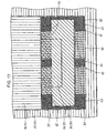
- body ply codes 32 are parallel arranged in a single body ply 31 to be coated in a rubber layer at an oblique angle in the range of 85 to 90 degrees relative to the tire circumferential direction.
- Two oblique belt layers 33 and 34 are arranged on the outer circumference of the body plies 31 in the circumferential direction.
- respective belt codes 35 made of steel are arranged at an angle in the range 30 to 60 degrees (preferably, in the range of 40 to 50 degrees) relative to the circumferential direction with themselves extending at the same oblique angle in the same direction.
- the oblique belt layer 34 at the outer side is made to be in the range of 40 to 70 % of the oblique belt layer 33 at the inner side in width and is arranged at the center portion in the direction of the radial tire width.
- the width of the oblique belt layer 33 at the inner side may be made to be in the range of 40 to 70 % of that of the oblique belt layer at the outer side.
- a spirally wound belt layer 36 is formed by spirally winding a belt code 9 almost in parallel with the tire circumferential direction.
- the belt code 9 is made by bundling and rubber-coating three hybrid codes 29 each of which is small in the increase rate of tensile load to stretch rate in a smaller stretch rate range than a predetermined stretch rate range but is large in the increase rate of tensile load in another range exceeding the predetermined stretch rate.
- a belt layer 37 is composed of the two oblique belt layers 33, 34 and the spirally wound belt layer 36.
- the two oblique belt layers 33, 34 in which the belt codes 35 made of steel are arranged to incline in the same direction at the same oblique angle relative to the circumferential direction are wound at the outer circumference of the body ply 31, and the belt code 9 made of the hybrid code 29 and coated with rubber is arranged at the outer circumference of the oblique belt layers 33, 34 in a spiral winding fashion to extend almost in parallel with the tire circumferential direction.
- the ground contact surface is made to be even and flat, whereby also with the hoop effect by the circumferentially spirally wound belt layer, improvements can be made in the steering stability, the wear resistance and the braking performance of the tire and particularly, in the braking performance on wet roads.
- the two oblique belt layers 33, 34 are wound with the respective belt codes inclined at the same angle in the same direction, so that though the ground contact area appears unchanged, the substantial ground contact area which works for the braking performance and the steering stability can be made to be large thereby to improve the braking performance and the steering stability.
- one oblique belt layer 34 of the two oblique belt layers 33, 34 is in the range of 40 to 70 % of the other oblique belt layer 33 in width and is circumferentially arranged at the center portion in the direction of the radial tire width, the floating motion which is liable to occur at the center portion of the tread surface when a sudden increase in load is brought about by braking can be suppressed, and the flexibility of the tread surface can be maintained.
- the width of the oblique belt layer 34 is made to be narrower than the 40 % width of the oblique belt layer 33, the center portion of the tread section becomes liable to float, and where it is made to be more than the 70 % width of the oblique belt layer 33, the flexibility of the tread section is deteriorated to make the riding comfortableness and the noise in the car worse.
- Fourth and fifth embodiments which will be described hereafter are different from the third embodiment only in the structure that a ply 41 under the oblique belt layers is arranged between the oblique belt layer 33 and the outer circumference of the body ply 31. Therefore, this difference will be described, and other components given the same reference numerals as those in the third embodiment will be omitted from being described.
- an organic fiber code 41 made of a single hybrid code 29 or plural twisted hybrid codes 29 is coated with rubber and is arranged to be spirally wound between the oblique belt layers 33, 34 and the outer circumference of the body ply 31 almost in parallel with the circumferential direction thereby to form a ply 42 under the oblique belt layers.
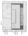
- the number of the organic fiber codes 41 arranged in the ply 42 under the oblique belt layers is such that each of the shoulder portions 43 on the side edges in the direction of the radial tire width is densified to have the organic fiber codes 41 in the number of 14 ⁇ 10 or so per 10 mm and that the center portion 44 is made to be loose and to have the organic fiber codes 41 of the number in the range of 40 to 85 %, desirably in the range of 50 to 80 % of those at each shoulder portion 43.
- the organic fiber codes 41 may be arranged to be gradually loose toward the tire center.
- the ply 42 under the oblique belt layers is arranged to extend from the shoulder portions 43 to the center portion 44 on the outer circumference of the body ply 31.
- the ply 42 under the oblique belt layers suppresses the separations between the body ply codes 32, so that differences in tension among the body ply codes 32 can be lessened to enhance the braking performance.
- the tire can be further stabled to keep its predetermined shape.
- the organic fiber code 41 in the ply 42 under the oblique belt layers is arranged to be densified at the shoulder portions 43 and to be loose at the center portion 44.
- the ground contact state of the shoulder portions 42 can be kept stable because of the densified arrangement of the organic fiber code 41 thereat.
- it can be realized to remarkably enhance the steering stability and the braking performance of the tire on wet roads and also to enhance the braking performance and the wear resistance on dry roads.
- the organic fiber code 41 is arranged to be loose at the center portion 44, whereby the separations between the body ply codes 32 and the floating due to the centrifugal force can be suppressed without deteriorating the flexibility.
- a waved steel code 50 given a waving processing as shown in Figure 15 is coated with rubber and is arranged to be spirally wound between the oblique belt layers 33, 34 and the outer circumference of the body ply 31 at each of the shoulder portions 43 almost in parallel with the circumferential direction.
- the waved steel code 50 it is preferred to use one which meets the requirements that a value H/d which is obtained by dividing the amplitude H (i.e., the distance between the top of a wave and the top of another wave directed in the opposite direction) by a code diameter d comes in the range of 1.1 to 3.0 and that a value L/d which is obtained by dividing the wavelength L by the code diameter comes in the range of 2 to 100.
- an organic fiber code 51 made of the single hybrid code 29 or the plural twisted hybrid codes 29 is spirally wound and arranged to be loose between the oblique belt layers 33, 34 and the outer circumference of the body ply 31 almost in parallel with the circumferential direction.
- a ply 52 under the oblique belt layers is formed with the steel code 50 arranged at the shoulder portions 43 and with the organic fiber code 51 arranged at the center portion 44.
- the ply 52 under the oblique belt layers suppresses the separations between the body ply codes 32, so that differences in tension among the body ply codes 32 can be lessened to enhance the braking performance.
- the waved steel code 50 is employed for the material at the shoulder portions 43 of the ply 52 under the oblique belt layers, the shoulder portions 43 are increased in rigidity and are further stabilized in the ground contact state upon sudden braking.
- remarkable improvements can be made in the braking performance and the steering stability of the tire on wet roads, and improvements can also be made in the braking performance and the wear resistance on dry roads.
- the organic fiber code 51 spirally wound to be loose the floating of center portion 44 can be suppressed to the extent that the flexibility cannot be deteriorated.
- the organic fiber codes 41, 51 each made of the single hybrid code 29 or the plural twisted hybrid codes 29 are used to form the plies 42, 52 under the oblique belt layers respectively
- an ordinary organic fiber code that is, a code (e.g., Nylon 1400detex/2) made by twisting two nylon fiber bundles may be used to form the plies 42, 52 under the oblique belt layers .
- the waved steel code 50 (refer to Figure 15) given the waving processing is coated with rubber and is arranged to be spirally wound between the oblique belt layer 33 and the outer circumference of the body ply 31 almost in parallel with the circumferential direction thereby to form a ply 62 under the oblique belt layers.
- the number of the steel codes 50 arranged in the ply 62 under the oblique belt layers is such that each of the shoulder portions 43 on the side edges in the direction of the radial tire width and the center portion 64 is densified to have the steel codes 50 in the number of 14 ⁇ 10 or so per 10 mm and that a portion between each shoulder portion 43 and the center portion 64 is made to be loose and to have the steel codes 50 of the number in the range of 40 to 85 %, preferably in the range of 50 to 80 % of those at each shoulder portion 43.
- the waved steel code 50 is moderately stretched not to deteriorate the entire shape of the tire.
- the organic fiber code 51 made of the hybrid code 29 may be used for the code in the ply 62 under the oblique belt layers.
- the ply 62 under the oblique belt layers is arranged on the outer circumference of the body ply 31 to extend from the shoulder portions 43 to the center portion 64, and thus, when a sudden load acts upon braking, the ply 62 under the oblique belt layers suppresses the separations between the body ply codes 32, so that differences in tension among the body ply codes 32 can be lessened to enhance the braking performance.
- the code in the ply 62 under the oblique belt layers is arranged to be densified at the shoulder portions 43 and the center portion 64 but to be loose at the portion between each shoulder portion 43 and the center portion 64, the loose areas help to lighten the tire, and at the same time, the ground contact state is kept to be always stable at the shoulder portions 43 and the center portion 64 where the code arrangement is densified.
- remarkable improvements can be made in the steering stability and the braking performance of the tire on wet roads, and improvements can also be made in the braking performance and the wear resistance on dry roads.
- the code arrangement is densified at the center portion 64, the floating of the center portion in high speed traveling can be suppressed to improve the steering stability in high speed traveling. Accordingly, the tire is suitable for use as those for sports-oriented vehicles in which importance is placed on the steering stability.
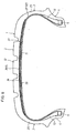
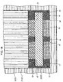
- a seventh embodiment shown in Figure 17 is such that in the sixth embodiment, the waved steel code 50 (refer to Figure 15) given the waving processing is coated with rubber and is also arranged to be spirally wound between the circumferentially spirally wound belt layer 36 and the oblique belt layers 33, 34 almost in parallel with the circumferential direction thereby to form a ply 65 under the spirally wound belt layer.
- the number of the steel codes 50 arranged in the ply 65 under the spirally wound belt layer is such that each of the shoulder portions 43 on the side edges in the direction of the radial tire width and the center portion 64 is densified to have the steel codes 50 in the number of 14 ⁇ 10 or so per 10 mm and that the portion between each shoulder portion 43 and the center portion 64 is made to be loose and to have the steel codes 50 of the number in the range of 40 to 85 %, preferably in the range of 50 to 80 % of those at each shoulder portion 43.
- the waved steel code 50 is moderately stretched not to deteriorate the entire shape of the tire.
- the organic fiber code 51 made of the hybrid code 29 may be used for the code in the ply 65 under the spirally wound belt layer.
- the ply 62 under the oblique belt layers suppresses the separations between the body ply codes 32, so that differences in tension among the body ply codes 32 can be lessened to enhance the braking performance.
- the shoulder portions 43 and the center portion 64 are heightened in rigidity, and the ground contact state at the shoulder portions 43 upon sudden braking is stabilized.
- remarkable improvements can be made in the braking performance and the steering stability of the tire on wet roads, and improvements can also be made in the braking performance and the wear resistance on dry roads.
- the floating of the center portion in high speed traveling can be suppressed to improve the steering stability in high speed traveling.
- the ply 65 under the spirally wound belt layer is arranged between the circumferentially spirally wound belt layer 36 and the oblique belt layers 33, 34, the hoop effect on the body ply 32 can further be strengthened thereby to improve the steering stability and the wear resistance.
- the steel codes 35 of the oblique belt layers 33, 34 are tightly sandwiched and tied by the ply 65 under the spirally wound belt layer and the ply 62 under the oblique belt layers at the shoulder portions 43 and the center portion 64, the movements of the steel codes 35 in the oblique belt layers 33, 34 are restricted during the rolling of the tire, whereby the noise in the car can be reduced.
- An eighth embodiment shown in Figure 18 is such that in the seventh embodiment, the oblique belt 34 is removed to leave the oblique belt 33 only. In comparison with the seventh embodiment, the eighth embodiment is advantageous in lightening the tire though the operation and effect of the oblique belt 34 can no longer be expected.
- Example 1 to 5 were manufactured based on the foregoing first to fifth embodiments and were compared with a trial tire which is shown as prior art in Figures 19 and 20 to show the test results of comparison in performance.
- Used for compassion were low-aspect pneumatic tires each having a tire size of 215/45ZR17, and tests were carried out for dry-road braking performance, wet-road braking performance, steering stability and wear resistance.
- Each test result was evaluated using an index compared with the index !00 given to the result of the prior art trial tire. Values of the test results are indicated in Table 1, wherein a larger index means a better performance.
- ABS anti-skid brake system
- the compared tires were attached to the car with the ABS.
- the car running on a wet road of about 1mm water depth at the speed of 100 km/h was suddenly braked to the extent that the ABS works, and the braking distance through which the car ran until stopped was measured.
- the compared tires were attached to rims of the type 7JJ, and air was filled in each tire to make the inside pressure 240 kPa.
- the rims were attached to a car with an engine having the displacement of 2000 cc (i.e., 2-liter engine), and the car was steered to go straight ahead and to make lane changes at speeds in the range of 60 to 180 km/h on a circuit course.
- the steering stability was evaluated in dependence on the driver's feeling.
- a belt code may be selected from belt codes which have a property between the properties (a) and (b), that is, a property that the stretch rate indicates 0.5 % or more at the tensile load of 20 N and that the tensile load indicates 60N or more at the stretch rate of 3 % (preferably, the tensile load indicates 30N or more at the stretch rate of 1.5 %) and which meet the vulcanizing and forming conditions.
- the green tire when expanded in its outer diameter at an expansion rate in the range of 0.5 to 3 %, the green tire can be vulcanized and formed with various parts thereof reliably fit in each segment and hence, with the entire shape thereof kept properly.
- the radial tire with a circumferentially spirally wound belt layer according to the present invention is suitable for use as tires for wheels of motor vehicles.
Abstract
Description
- The present invention relates to a radial tire having belt codes of a belt layer which are arranged to be spirally wound almost in parallel with a tire circumferential direction.
- For further enhancement of vehicle safety, it has been an increasing strong demand to improve the braking performance and the steering stability of tires contacting with a road surface. Another increasing strong demand is to lighten tires for improved fuel efficiency in terms of environment preservation. To this end, there has been proposed a radial tire described in Japanese unexamined, published patent application No. 62-152904. In the known radial tire, body ply codes which extend from a tread section to each sidewall section to be turned up over a bead core of a bead section are arranged in a radial code fashion (arrangement at an angle in the range of 85 to 90 degrees relative to the tire circumferential direction), a secondary belt layer in which steel codes are inclined at an angle in the range of 20 to 40 degrees relative to the tire circumferential direction is arranged as a single layer over an outer circumference for a tread section of the body ply in the tire circumferential direction, and a steel code or an organic fiber code such as Kevlar® which is large in the increase rate of tensile load to stretch rate is spirally wound on an outer circumference side of the oblique belt layer almost in parallel with the tire circumferential direction to form a main belt layer. The belt layers are to prevent the movement of the body ply by a so-called "hoop effect" which suppress the radial expansion of the body ply for securing the steering stability, high-speed endurance and wear resistance which are characteristic performances of radial tires. As belt codes arranged in the belt layers, there have been used steel codes and aromatic polyamide fibers which are large in the increase rate of tensile road to stretch rate for a greater "hoop effect".
- On the other hand, in Japanese unexamined, published patent application No. 8-318706, there is described a radial tire wherein PET (polyethylene terephthalate) fiber or nylon fiber which is small in the increase rate of tensile load to stretch rate is used for a circumferential belt layer with the ply structure appropriated.
- Further, for a proper "hoop effect" by belt layers, a trial manufacture has been made of a radial tire, in which as shown in Figures 19 and 20, two
secondary belt layers body ply 70 in the tire circumferential direction, and an organic fiber code is spirally wound on an outer circumference side of theoblique belt layer 72 at the outside almost in parallel with the tire circumferential direction thereby to form amain belt layer 73. - In vulcanizing a so-called "green tire" formed with unvulcanized compounded rubber in a manufacturing process of tires, the green tire is put in a mold and is vulcanized and formed in the mold with heat and pressure being applied inside. To obtain a target tire shape by the vulcanization and forming, the green tire is expanded within the mold to add a stretch of several percents or, in dependence upon the type of the forming method, 0.5 to 3 %. Where there are employed conventional steel codes or aromatic polyamide fibers which hardly stretch because being large in the increase rate of tensile load to stretch rate, a problem arises in that they cannot be stretched by the pressure applied to the green tire up to 0.5 to 3 %, whereby the green tire cannot be formed to a correct shape as a result that the body ply codes are prevented by the non-stretchable belt code from being expanded. On the other hand, in the case of a radial tire which employs as belt codes PET or nylon fiber codes which are small in the increase rate of tensile load to stretch rate, there arises a problem that a sufficient hoop effect cannot be obtained after the vulcanization and forming.
- The present invention is made to solve the aforementioned problems and is to provide a radial tire with a belt layer in which there is circumferentially spirally wound a belt code capable of allowing the green tire to expand with a correct shape retained during a vulcanizing and forming process and also capable of exercising a sufficient hoop effect after the vulcanizing and forming process.
- A first invention resides in a radial tire provided with a body ply extending from a tread section to sidewall sections and having at both side ends thereof turned-up portions which are turned up over bead cores of bead sections; a belt layer wound on an outer circumference of the body ply in a tire circumferential direction; a tread circumferentially arranged on an outer circumference of the belt layer; and bead fillers extending from the bead cores radially outward between the sidewall sections and the turned-up portions of the body ply, wherein the belt layer comprises at least one spirally wound belt layer in which one or plural belt codes coated with rubber are arranged to be spirally wound almost in parallel with the tire circumferential direction; and wherein the belt code in the spirally wound belt layer is small in the increase rate of tensile load to stretch rate in the range of a predetermined stretch rate or less but is larger in the increase rate of tensile load in a range exceeding the predetermined stretch rate.
- According to the present invention, since during a vulcanizing and forming process, the belt code is expanded under a small tensile load not to prevent body ply codes from expanding, a green tire is vulcanized and formed with respective parts thereof being adhered as a result of being expanded to keep a regular shape. Thus, the tire is vulcanized and formed with the belt code being expanded by the predetermined stretch rate and after the vulcanization, becomes large in the increase rate of tensile road to stretch rate to exercise a sufficient hoop effect. Therefore, the tire can be well maintained in a desired toroidal shape, can be increased in a forward-rearward rigidity in the tire circumferential direction, can suppress the movement of the treading surface, can be enhanced in the braking performance to avoid collisional accident, and further can make the shape of a ground contact surface on the treading surface proper. As a consequence, it becomes possible to make sudden starting and sharp steering as well as to enhance steering stability.
- A second invention resides in a radial tire with the circumferentially spirally wound belt layer according to the aforementioned first invention, wherein the belt code in the spirally wound belt layer is of the property that the stretch rate is equal to or greater than 0.5 % at the tensile load of 20 N and that the tensile load at the stretch rate of 3 % is equal to or greater than 60 N (preferably, the tensile load at the stretch rate of 1.5 % is equal to or greater than 30 N).
- According to the present invention, as is the case of the first invention, when the diameter of the green tire is expanded at an expansion rate in the rage of 0.5 to 3 %, the tire is vulcanized and formed with respective parts thereof being adhered as a result of having the entire shape thereof maintained properly and after the vulcanization and forming, becomes large in the hoop effect that the belt layer suppresses the expansion of the body ply.
- A third invention resides in a radial tire with the circumferentially spirally wound belt layer according to the aforementioned first or second invention, wherein the belt code in the spirally wound belt layer is made of a hybrid code having a nylon fiber bundle as a core and having an aramid fiber bundle twisted therearound.
- According to the present invention, it can be realized to provide a light belt code having a property that the increase rate of tensile load to stretch rate is small in the range of a predetermined stretch rate or less, but is large in the increase rate of tensile load in a range exceeding the predetermined stretch rate.
- A fourth invention resides in a radial tire with the circumferentially spirally wound belt layer according to the aforementioned first or second invention, wherein the belt code in the spirally wound belt layer is made of a multi-strand steel code which is made by twisting plural steel strands.
- According to the present invention, it can be realized to provide a belt code which is small in the increase rate of tensile load to stretch rate in the range of a predetermined stretch rate or less, but abruptly increases the increase rate of tensile load in a range exceeding the predetermined stretch rate to have a large hoop effect.
- A fifth invention resides in a radial tire with the circumferentially spirally wound belt layer according to the aforementioned first or second invention, wherein the belt code in the spirally wound belt layer is made of a waved steel code which is made by giving a waving processing to a steel code which is made by twisting plural steel filaments.
- According to the present invention, it can be realized to easily adjust the property of the steel belt code which is large in the hoop effect as being small in the increase rate of tensile load to stretch rate in the range of a predetermined stretch rate or less, but abruptly increasing the increase rate of tensile load in a range exceeding the predetermined stretch rate.
- A sixth invention resides in a radial tire with the circumferentially spirally wound belt layer according to any one of the aforementioned first to fifth inventions, wherein the body ply is arranged to be at least one layer; wherein body ply codes in the body ply are inclined at an angle in the range of 85 to 90 degrees relative to the circumferential direction; and wherein the belt layer arranged on the outer circumference of the body ply comprises an oblique belt layer in which a belt code made of steel is arranged as one layer to be inclined at an angle in the range of 10 to 40 degrees relative to the circumferential direction and at least one spirally wound belt layer in which a belt code is spirally arranged on an outer circumference of the oblique belt layer almost in parallel with the tire circumferential direction.
- According to the present invention, in addition to the effects of the first invention, it can be realized to lighten the radial tire, to enhance the braking performance and the steering stability of the tire and to maintain the high-speed endurance and the wear resistance.
- A seventh invention resides in a radial tire with the circumferentially spirally wound belt layer according to any one of the aforementioned first to third inventions, wherein the body ply is arranged to be at least one layer; wherein body ply codes in the body ply are inclined at an angle in the range of 85 to 90 degrees relative to the circumferential direction; and wherein the belt layer arranged on the outer circumference of the body ply comprises two oblique belt layers in which belt codes made of steel are arranged to be inclined in the same direction at the same angle in the range of 30 to 60 degrees (preferably, in the range of 40 to 50 degrees) relative to the circumferential direction and at least one spirally wound belt layer in which a rubber-coated belt code made of a hybrid code is spirally arranged on outer circumferences of the oblique belt layers almost in parallel with the tire circumferential direction; and wherein of the two oblique belt layers, one oblique belt layer is in the range of 40 to 70 % of the other oblique belt layer in width and is circumferentially arranged at the center portion in the direction of the radial tire width.
- According to the present invention, by the hoop effects of the two belt layers inclined in the same direction and the circumferentially spirally wound belt layer, it can be realized to enhance the braking performance, the steering stability and the wear resistance of the tire and in particular, to enhance the braking effect on wet roads. It is usual that in the steel belt arranging structure, two belt layers are arranged to have respective belt codes wound and inclined in opposite directions and crossed mutually. In that case, respective belt codes interfere to be twisted, and this causes the distribution of the ground contact pressure on the ground contact surface to be uneven and not to become flat, so that though the ground contact area appears unchanged, there is decreased a substantial ground contact area which works for the braking performance and the steering stability. On the other hand, in the present invention, since the two oblique belt layers are wound with the belt codes being inclined at the same angle in the same direction, the distribution of the ground contact pressure on the ground contact surface becomes even and flat, so that though the ground contact area appears unchanged, the substantial ground contact area which works for the braking performance and the steering stability can be made to be large thereby to improve the braking performance and the steering stability. Further, since one oblique belt layer of the two oblique belt layers is in the range of 40 to 70 % of the other oblique belt layer in width and is circumferentially arranged at the center portion in the direction of the radial tire width, the floating motion which is liable to occur at the center portion of the tread surface when a sudden increase in load is brought about upon braking can be suppressed, and the flexibility of the tread section can be maintained.
- An eighth invention resides in a radial tire with the circumferentially spirally wound belt layer according to the aforementioned seventh invention, wherein an organic fiber code made of a hybrid code is coated with rubber and is arranged to be spirally wound between the oblique belt layers and the outer circumference of the body ply almost in parallel with the circumferential direction thereby to form a ply under the oblique belt layers; and wherein the arrangement of the organic codes in the ply under the oblique belt layers is made to be densified at shoulder portions on the side edges in the direction of the radial tire width and is made to be loose at the center portion.
- According to the present invention, the ply under the oblique belt layers is arranged on the outer circumference of the body ply to extend from the shoulder portions to the center portion, and thus, when a sudden load acts upon braking, the ply under the oblique belt layers suppresses the separations between the body ply codes, so that differences in tension among the body ply codes can be lessened to enhance the braking performance. Further, the code in the ply under the oblique belt layers is arranged to be densified at the shoulder portions and to be loose at the center portion, and thus, when an inside pressure is applied to the tire, the ground contact state of the shoulder portions can be kept stable because of the densified arrangement of the organic fiber code thereat, so that it can be realized to remarkably enhance the steering stability and the braking performance of the tire on wet roads and also to enhance the braking performance and the wear resistance on dry roads. At the center portion, the organic fiber code is arranged to be loose, so that the separations between the body ply codes can be suppressed without deteriorating the flexibility.
- A ninth invention resides in a radial tire with the circumferentially spirally wound belt layer according to the aforementioned seventh invention, wherein a ply under the oblique belt layers is composed of a waved steel code coated with rubber and arranged to be spirally wound and to be densified between the oblique belt layers and the outer circumference of the body ply at shoulder portions on the side edges in the direction of the radial tire width almost in parallel with the circumferential direction and an organic fiber code made of a hybrid code coated with rubber and arranged to be spirally wound and to be loose between the oblique belt layers and the outer circumference of the body ply at the center portion almost in parallel with the circumferential direction.
- According to the present invention, when a sudden load acts upon braking, the ply under the oblique belt layers suppresses the separations between the body ply codes, so that differences in tension among the body ply codes can be lessened to enhance the braking performance. Further, since the waved steel code is employed as the material at the shoulder portions of the ply under the oblique belt layers, the shoulder portions of the radial tire are increased in rigidity and further are stabilized in the ground contact state upon sudden braking. Thus, remarkable improvements can be made in the braking performance and the steering stability of the tire on wet roads, and improvements can also be made in the braking performance and the wear resistance on dry roads. By the organic fiber code spirally wound to be loose, the floating of the center portion can be suppressed to the extent that the flexibility cannot be deteriorated.
- A tenth invention resides in a radial tire with the circumferentially wound belt layer according to the aforementioned seventh invention, wherein a code which is small in the increase rate of tensile load to stretch rate in the range of a predetermined stretch rate or less but is large in the increase rate of tensile load in a range exceeding the predetermined stretch rate is coated with rubber and is arranged to be spirally wound between the oblique belt layers and the outer circumference of the body ply almost in parallel with the circumferential direction thereby to form a ply under the oblique belt layers, and wherein the code in the ply under the oblique belt layers is arranged to be densified at the shoulder portions on the side edges in the direction of the radial tire width and at the center portion, but to be loose at a portion between each shoulder portion and the center portion.
- According to the present invention, the ply under the oblique belt layers is arranged on the outer circumference of the body ply to extend from the shoulder portions to the center portion, and thus, when a sudden load acts upon braking, the ply under the oblique belt layers suppresses the separations between the body ply codes, so that differences in tension among the body ply codes can be lessened to enhance the braking performance. In addition, since the code in the ply under the oblique belt layers is arranged to be densified at the shoulder portions and the center portion and to be loose at the portion between each shoulder portion and the center portion, the loose portion serves for lightening the tire, and at the same time, the ground contact state is kept to be always stable at the shoulder portions and the center portion where the code arrangement is densified. Thus, remarkable improvements can be made in the steering stability and the braking performance of the tire on wet roads, and improvements can also be made in the braking performance and the wear resistance on dry roads. Because of being densified at the center portion, the floating of the center portion in high speed traveling can be suppressed to improve the steering stability in high speed traveling.
- An eleventh invention resides in a radial tire with the circumferentially spirally wound belt layer according to the aforementioned tenth invention, wherein a code which is small in the increase rate of tensile load to stretch rate in the range of a predetermined stretch rate or less but is large in the increase rate of tensile load in a range exceeding the predetermined stretch rate is coated with rubber and is arranged to be spirally wound between the spirally wound belt layer and the oblique belt layers almost in parallel with the circumferential direction thereby to form a ply under the spirally wound belt layer, and wherein the code in the ply under the spirally wound belt layer is arranged to be densified at the shoulder portions on the side edges in the direction of the radial tire width and at the center portion, but to be loose at the portion between each shoulder portion and the center portion.
- According to the present invention, when a sudden load acts upon braking, the ply under the oblique belt layers suppresses the separations between the body ply codes, so that differences in tension among the body ply codes can be lessened to enhance the braking performance. In addition, the shoulder portions and the center portion are heightened in rigidity, and the ground contact state at the shoulder portions upon sudden braking is stabilized. Thus, remarkable improvements can be made in the braking performance and the steering stability of the tire on wet roads, and improvements can also be made in the braking performance and the wear resistance on dry roads. The floating of the center portion in high speed traveling can be suppressed to improve the steering stability in high speed traveling. Furthermore, since the ply under the spirally wound belt layer is arranged between the circumferentially spirally wound belt layer and the oblique belt layers, the hoop effect on the body ply can further be strengthened thereby to improve the steering stability and the wear resistance. In addition, since the steel codes in the oblique belt layers are sandwiched and tied by the ply under the spirally wound belt layer and the ply under the oblique belt layers to be densified at the shoulder portions and the center portion, the movement of the steel codes in the oblique belt layers is restricted during the rolling of the tire, whereby reduction can be made in the noise in the car on rough roads.
- A twelfth invention resides in a radial tire with the circumferentially spirally wound belt layer according to any one of the aforementioned sixth to eleventh inventions, wherein both side portions of the spirally wound belt layer cover both side portions of the oblique belt layers.
- According to the present invention, it can be prevented that both side portions of the codes in the oblique belt layers are brought into contact with the tread internal surface thereby to become a core for troubles.
- Figure 1 is a sectional view of a radial tire, taken in a tire radial direction, having circumferentially spirally wound belt layers in a first embodiment; Figure 2 is a figure showing a body ply and the belt layers in the first embodiment; Figure 3 is a figure showing the states of a belt code and belt codes coated with unvulcanized compounded rubber; Figure 4 is a graph showing tensile loads of belt codes relative to stretch rates; Figure 5 is a perspective view of a multi-strand steel code; Figure 6 is a sectional view of a radial tire, taken in a tire radial direction, having circumferentially spirally wound belt layers in a second embodiment; Figure 7 is a figure showing body plies and the belt layers in the second embodiment; Figure 8 is a perspective view of a hybrid code; Figure 9 is a sectional view of a radial tire, taken in a tire radial direction, having circumferentially spirally wound belt layers in a third embodiment; Figure 10 is a figure showing a body ply and the belt layers in the third embodiment; Figure 11 is a sectional view of a radial tire, taken in a tire radial direction, having a circumferentially spirally wound belt layer in a fourth embodiment; Figure 12 is a figure showing the arrangement of a body ply, the oblique belt layers and a ply under the oblique belt layers in the fourth embodiment; Figure 13 is a sectional view of a radial tire, taken in a tire radial direction, having a circumferentially spirally wound belt layer in a fifth embodiment; Figure 14 is a figure showing the arrangement of a body ply, the oblique belt layers and a ply under the oblique belt layers in the fifth embodiment; Figure 15 is a perspective view of a steel code given a waving processing; Figure 16 is a figure showing the arrangement of a body ply, oblique belt layers and a ply under the oblique belt layers in a sixth embodiment; Figure 17 is a figure showing the arrangement of a body ply, oblique belt layers, a ply under the oblique belt layers and a ply under a spirally wound belt layer in a seventh embodiment; Figure 18 is a figure showing an eighth embodiment wherein the belt layers in Figure 17 are modified to include one oblique belt layer; Figure 19 is a sectional view of a prior art radial tire taken in a tire radial direction; and Figure 20 is a figure showing the arrangement of a body ply and belt layers of the prior art radial tire.
- Hereafter, description will be made with reference to the accompanying drawings as to a radial tire having circumferentially spirally wound belt layers in the first embodiment in which the present invention is applied to a radial tire for passenger cars. As shown in Figures 1 and 2, the
radial tire 1 is composed of atread section 2,sidewall sections 3 at both sides of the tire radially bent from both sides of thetread section 2 toward the tire axis, andannular bead sections 4 constituting inner circumferences of therespective sidewall sections 3. Thebead sections 4 at the both sides are provided withbead cores 5 each constituted by annually winding a steel code. A body ply 6 extends from thetread section 2 to pass through thesidewall sections 3 at the both sides and then to be turned up over therespective bead cores 5, so that thebody play 6 is suspended between the both side beads. In thebody ply 6, body plycodes 7 are coated with rubber and are arranged at an oblique angel in the range of 85 to 90 degrees relative to the tire circumferential direction. With the arrangement of the body ply codes at the oblique angle in the range of 85 to 90 degrees as well as with an excellent hoop effect of a spirallywound belt layer 10 having thebelt code 9 spirally wound in the tire circumferential direction, the radial tire can easily be kept in a desired toroidal shape and thus, can be excellent in the braking performance and the steering stability. - The spirally
wound belt layer 10 comprising twolayers body ply 6, and in each of the layers, abelt code 9 having an appropriate tensile rigidity is coated with rubber and is spirally wound at an oblique angle in the range of 0 to 9 degrees almost in parallel with the tire circumferential direction. In this case, the spirallywound belt layer 10 may be formed by spirally winding asingle belt code 9 in turn for thefirst layer 9a and thesecond layer 9b with the circumferential surface of thebelt code 9 coated with unvulcanized compounded rubber as shown in Figure 3(a). Or, the spirallywound belt layer 10 may be constituted by spirally winding plural belt codes simultaneously in turn for thefirst layer 9a and thesecond layer 9b with the plural belt codes coated with unvulcanized compounded rubber in a parallel arrangement to form a ribbon as shown in Figure 3(b). Or, the spirallywound belt layer 10 may be constituted by spirally winding, by one turn, plural belt codes of double layers which are coated with unvulcanized compounded rubber in parallel arrangements with one layer for thefirst layer 9a piled up on the other layer for thesecond layer 9b as shown in Figure 3(c). A manufacturing method of spirally winding the rubber-coatedbelt codes 9 on the outer circumference of the body ply 6 can be implemented by a known method described in, e.g., Japanese unexamined, published patent application No. 2002-137607 and is therefore omitted from being described. - As referred to later, finally, the
belt codes 9 are spirally wound to form two layers almost in parallel with the tire circumferential direction with the increase rate of tensile load to stretch rate kept to be large. Thus, the hoop effect that the spirallywound belt layer 10 prevents the body ply 6 from expanding becomes large to keep the tire properly in a desired toroidal shape, and the forward-rearward rigidity in the tire circumferential direction can be increased to suppress the displacement of the tread surface, so that the braking performance can be enhanced to prevent collisional accidents. Further, the steering stability can be improved since sudden starting and sharp steering become possible. - An
inner liner 11 is arranged on the internal surface of thebody ply 6, atread 12 is wound on the outer surface of the spirally wound belt layers 10, abead filler 13 is arranged between each sidewall section and each turned-up portion of the body ply 6 to extend from eachbead core 5 radially outward of the tire, and aside tread 20 is arranged at each of thesidewall section 3. - A green tire whose structure roughly described above is formed with unvulcanized compounded rubber is put into a vulcanizing mold, and then, an expansible shape fit in the internal surface of the
inner liner 11 is expanded while they are heated up to about 200 degrees centigrade, whereby theinner liner 11, thebody ply 6, the spirally wound belt layers 10 and thetread 12 are adhered and formed together through the vulcanization of the unvulcanized compounded rubber. The expansion of the expansible shape causes the tire outer diameter to expand at an expansion rate in the range of 0.5 to 3 %, and therefore, unless thebelt codes 9 can be expanded under a small tensile load during this expansion process, the correct tire shape cannot be kept as a result that the body plycodes 7 are prevented by theunexpanded belt codes 9 from being expanded. - In view of the above, various tests were carried out with tire vulcanization and forming conditions changed. From the test results, it was found that in the case of using for the
belt codes 9 a code which was manufactured to have the property that as shown in Figure 4, the stretch rate at the tensile load of 20 N (newton) is equal to or greater than 0.5 % and that the tensile load at the stretch rate of 3 % is equal to or greater than 60 N (preferably, the tensile load at the stretch rate of 1.5 % is equal to or greater than 30 N), theinner liner 11, thebody ply 6, the spirallywound belt layer 10 and thetread 12 were reliably adhered and vulcanized with the entire shape of the tire kept properly during the expansion of the expansible shape. In this case, since the tire is vulcanized and formed with thebelt code 9 being stretched at a stretch rate in the range of 0.5 to 3 %, the vulcanized and formed tire is heightened in the tensile rigidity of thebelt code 9 and is increased in the hoop effect that the spirallywound belt layer 10 prevents the body ply 6 from expanding. Thus, the tire can be kept properly in a desired toroidal shape, so that improvements can be made in the braking performance and the steering stability. - The
belt code 9 used as one example in the first embodiment was a steel code with a structure of 3 x 3 x 0.175. This is amulti-strand steel code 19 having a code diameter of 0.81 Φmm (millimeter) which code is structured by twisting three steel filaments 18a of the diameter 0.175 Φmm to make astrand 18b and then by twisting threestrands 18b so made at a short pitch. As indicated at (a) in Figure 4, the property of the tensile load relative to the stretch rate of themulti-strand steel code 19 indicates the stretch rate of 0.6 % larger than 0.5 % at the tensile load of 20 N, attains the tensile load of 350 N at the stretch rate of 1.5 %. At a stretch rate equal to or less than about 0.5 % which is a predetermined value, the increase rate of tensile load to stretch rate becomes small, but becomes large as the stretch rate exceeds the predetermined value. - The
belt code 9 used in the spirallywound belt layer 10 may be a wavedsteel code 50 shown in Figure 15. This wavedsteel code 50 is made by waving a steel code with the structure of 1 x 3 x 0.27 (i.e., a code of 0.58 Φmm code diameter which is made by twisting threesteel filaments 53 each having 0.27 Φmm). In the wavedsteel code 50, by altering the wave shape, it can be realized relatively easily to adjust a desired property that the increase rate of tensile load to stretch rate is small in a small load range but is large in a stretch rate range exceeding the predetermined value. - By the selection of the twisting method, any aramid code which is large in the increase rate of tensile load to stretch rate and small in the stretch rate of each fiber itself or any steel code can be made to a light belt code having a desired property that the increase rate of tensile load to stretch rate is small in a small load range but is large in a stretch rate range exceeding the predetermined value.
- The tensile tests for codes were performed by using a Model AGS-500A machine made by Shimadzu Corporation, Kyoto, Japan within a room which is maintained at 25 (room temperature) ± 3 degrees centigrade and 65 % in relative humidity under the conditions of the grip-to-grip interval of 250 mm and the stretching speeds of 300 mm/min for organic fiber codes and 125 mm/min for steel codes. As code samples, there were used those which were kept at a constant temperature (20 ± 2 degrees centigrade) within a tightly-closed bottle filled with 36 % sulfuric acid.
- In a second embodiment, as shown in Figures 6 and 7, body ply
codes 22 are coated with rubber and are parallel arranged in abody ply 21 composed of twolayers layer belt layer 23 is arranged on the outer circumference of thebody ply 21. The first layer inside in the tire radial direction is anoblique belt layer 25, in whichbelt codes 24 made of steel are coated with rubber and are arranged in a single layer to be inclined at an angle in the range of 10 to 40 degrees, preferably at an angle of 20 degrees. The second layer is a spirallywound belt layer 26 in which one ormore belt codes 9 coated withrubber 8 as shown in Figure 3(a) or 3(b) are spirally wound in a single layer at an oblique angle in the range of 0 to 9 degrees almost parallel with the tire circumferential direction. - For the
belt code 9 in the spirallywound belt layer 26, there is used a hybrid code 29 (refer to Figure 8) which is structured by twisting an aramid fiber bundle 27 (e.g., Aramid 1100 dtex) typifying aromatic polyamid fiber codes with a nylon fiber bundle 28 (e.g., Nylon 940 dtex) of aliphatic polyamide system. As indicated at (b) in Figure 4, the property of tensile load to stretch rate of thehybrid code 29 is such that the tensile load attains 80 N larger than 60 N at the stretch rate of 3 % and attains 300 N at the stretch rate of 6 % and that the increase rate of tensile load to stretch rate becomes small in a stretch rate range of about 3 % or less which is a predetermined value, but becomes large in another stretch rate range exceeding the predetermined value. The tensile load to stretch rate can be increased by bundling pluralhybrid codes 29. In the later mentioned second embodiment, threehybrid codes 29 were bundled to make a code of 1.08 Φmm in code diameter for use as thebelt code 9. It is possible to vary the aforementioned predetermined value by adjusting the twisting structure. - In the second embodiment, the
belt layer 23 comprise anoblique belt layer 25 arranging therein highrigidity steel codes 24 to incline at a small angle (in the range of 10 to 40 degrees) relative to the circumferential direction and a spirallywound belt layer 26 spirally arranging one or more rubber-coatedbelt codes 9 almost in parallel (in the range of 0 to 9 degrees) with the tire circumferential direction. Thus, the hoop effect can be exercised very strongly on thebody ply 6, so that improvements can be made in the braking performance and the steering stability. Further, since theoblique belt layer 25 including thesteel codes 24 is one layer, it can be realized to lighten the tire as well as to achieve an advantage of a small rolling resistance. In addition, since thebelt code 9 used for the spirallywound belt layer 26 is made of a bundle of pluralhybrid codes 29 each making a core with the nylon fiber bundle 28 and having thearamid fiber bundle 27 twisted therearound, thebelt code 9 can be obtained as that which is proper in the increase rate of tensile load to stretch rate and which is light. Therefore, it can be also realized to lighten the tire as well as to reduce the occurrence of defectives in the tire production. - In a third embodiment, as shown in Figures 9 and 10, body ply
codes 32 are parallel arranged in a single body ply 31 to be coated in a rubber layer at an oblique angle in the range of 85 to 90 degrees relative to the tire circumferential direction. Two oblique belt layers 33 and 34 are arranged on the outer circumference of the body plies 31 in the circumferential direction. In the two oblique belt layers 33 and 34,respective belt codes 35 made of steel are arranged at an angle in therange 30 to 60 degrees (preferably, in the range of 40 to 50 degrees) relative to the circumferential direction with themselves extending at the same oblique angle in the same direction. Of the two oblique belt layers 33 and 34, theoblique belt layer 34 at the outer side is made to be in the range of 40 to 70 % of theoblique belt layer 33 at the inner side in width and is arranged at the center portion in the direction of the radial tire width. Conversely, the width of theoblique belt layer 33 at the inner side may be made to be in the range of 40 to 70 % of that of the oblique belt layer at the outer side. On the outer circumference of the two oblique belt layers 33 and 34, a spirallywound belt layer 36 is formed by spirally winding abelt code 9 almost in parallel with the tire circumferential direction. Thebelt code 9 is made by bundling and rubber-coating threehybrid codes 29 each of which is small in the increase rate of tensile load to stretch rate in a smaller stretch rate range than a predetermined stretch rate range but is large in the increase rate of tensile load in another range exceeding the predetermined stretch rate. Abelt layer 37 is composed of the two oblique belt layers 33, 34 and the spirallywound belt layer 36. - In the third embodiment, the two oblique belt layers 33, 34 in which the
belt codes 35 made of steel are arranged to incline in the same direction at the same oblique angle relative to the circumferential direction are wound at the outer circumference of the body ply 31, and thebelt code 9 made of thehybrid code 29 and coated with rubber is arranged at the outer circumference of the oblique belt layers 33, 34 in a spiral winding fashion to extend almost in parallel with the tire circumferential direction. Thus, the ground contact surface is made to be even and flat, whereby also with the hoop effect by the circumferentially spirally wound belt layer, improvements can be made in the steering stability, the wear resistance and the braking performance of the tire and particularly, in the braking performance on wet roads. - It has been a practice that in the structural arrangement of steel belts, two belt layers are arranged to be wound with respective belt codes oriented in opposite directions to cross mutually. In that case, respective belt codes interfere to be twisted, and this causes the distribution of the ground contact pressure on the ground contact surface to be uneven and not to become flat, so that though the ground contact area appears unchanged, there is decreased a substantial ground contact area which works for the braking performance and the steering stability. On the other hand, in the third embodiment, since the two oblique belt layers 33, 34 are wound with the respective belt codes inclined at the same angle in the same direction, the distribution of the ground contact pressure on the ground contact surface becomes even and flat, so that though the ground contact area appears unchanged, the substantial ground contact area which works for the braking performance and the steering stability can be made to be large thereby to improve the braking performance and the steering stability.
- Further, since one
oblique belt layer 34 of the two oblique belt layers 33, 34 is in the range of 40 to 70 % of the otheroblique belt layer 33 in width and is circumferentially arranged at the center portion in the direction of the radial tire width, the floating motion which is liable to occur at the center portion of the tread surface when a sudden increase in load is brought about by braking can be suppressed, and the flexibility of the tread surface can be maintained. Where the width of theoblique belt layer 34 is made to be narrower than the 40 % width of theoblique belt layer 33, the center portion of the tread section becomes liable to float, and where it is made to be more than the 70 % width of theoblique belt layer 33, the flexibility of the tread section is deteriorated to make the riding comfortableness and the noise in the car worse. - Fourth and fifth embodiments which will be described hereafter are different from the third embodiment only in the structure that a
ply 41 under the oblique belt layers is arranged between theoblique belt layer 33 and the outer circumference of thebody ply 31. Therefore, this difference will be described, and other components given the same reference numerals as those in the third embodiment will be omitted from being described. - In the fourth embodiment, as shown in Figures 11 and 12, an
organic fiber code 41 made of asingle hybrid code 29 or plural twistedhybrid codes 29 is coated with rubber and is arranged to be spirally wound between the oblique belt layers 33, 34 and the outer circumference of the body ply 31 almost in parallel with the circumferential direction thereby to form aply 42 under the oblique belt layers. The number of theorganic fiber codes 41 arranged in theply 42 under the oblique belt layers is such that each of theshoulder portions 43 on the side edges in the direction of the radial tire width is densified to have theorganic fiber codes 41 in the number of 14 ±10 or so per 10 mm and that thecenter portion 44 is made to be loose and to have theorganic fiber codes 41 of the number in the range of 40 to 85 %, desirably in the range of 50 to 80 % of those at eachshoulder portion 43. At thecenter portion 44, theorganic fiber codes 41 may be arranged to be gradually loose toward the tire center. When an expansible shape is expanded with the green tire placed in a vulcanizing mold, theorganic fiber code 41 made of thehybrid code 29 moderately stretches not to deteriorate the entire shape of the tire. - In this manner, the
ply 42 under the oblique belt layers is arranged to extend from theshoulder portions 43 to thecenter portion 44 on the outer circumference of thebody ply 31. Thus, when a sudden load acts upon braking, theply 42 under the oblique belt layers suppresses the separations between the body plycodes 32, so that differences in tension among the body plycodes 32 can be lessened to enhance the braking performance. Further, when having an inside pressure applied thereto, the tire can be further stabled to keep its predetermined shape. In addition, theorganic fiber code 41 in theply 42 under the oblique belt layers is arranged to be densified at theshoulder portions 43 and to be loose at thecenter portion 44. Thus, when the inside pressure is applied to the tire, the ground contact state of theshoulder portions 42 can be kept stable because of the densified arrangement of theorganic fiber code 41 thereat. As a consequence, it can be realized to remarkably enhance the steering stability and the braking performance of the tire on wet roads and also to enhance the braking performance and the wear resistance on dry roads. While the floating of thecenter portion 44 due to the centrifugal force is suppressed primarily by thebelt layer 37, theorganic fiber code 41 is arranged to be loose at thecenter portion 44, whereby the separations between the body plycodes 32 and the floating due to the centrifugal force can be suppressed without deteriorating the flexibility. - In the fifth embodiment shown in Figure13 and 14, a waved
steel code 50 given a waving processing as shown in Figure 15 is coated with rubber and is arranged to be spirally wound between the oblique belt layers 33, 34 and the outer circumference of the body ply 31 at each of theshoulder portions 43 almost in parallel with the circumferential direction. As the wavedsteel code 50, it is preferred to use one which meets the requirements that a value H/d which is obtained by dividing the amplitude H (i.e., the distance between the top of a wave and the top of another wave directed in the opposite direction) by a code diameter d comes in the range of 1.1 to 3.0 and that a value L/d which is obtained by dividing the wavelength L by the code diameter comes in the range of 2 to 100. In the later described fifth embodiment, a code having a 1 x 3 x 0.20 structure (a code which was made by twisting threefilaments 53 each with 0.20 Φmm) and also having its code diameter of 0.424 Φmm before the waving processing was given the waving processing to be formed to a wave shape with the amplitude H = 0.68 mm and the wavelength L = 2.0 mm, and the code so waved was used. - When an expansible shape is expanded with the green tire placed in a vulcanizing mold, the waved
steel codes 50 are moderately stretched not to deteriorate the entire form of the tire. At thecenter portion 44, anorganic fiber code 51 made of thesingle hybrid code 29 or the plural twistedhybrid codes 29 is spirally wound and arranged to be loose between the oblique belt layers 33, 34 and the outer circumference of the body ply 31 almost in parallel with the circumferential direction. Aply 52 under the oblique belt layers is formed with thesteel code 50 arranged at theshoulder portions 43 and with theorganic fiber code 51 arranged at thecenter portion 44. - According to the fifth embodiment, as is the case of the fourth embodiment, when a sudden load acts upon braking, the
ply 52 under the oblique belt layers suppresses the separations between the body plycodes 32, so that differences in tension among the body plycodes 32 can be lessened to enhance the braking performance. Further, since the wavedsteel code 50 is employed for the material at theshoulder portions 43 of theply 52 under the oblique belt layers, theshoulder portions 43 are increased in rigidity and are further stabilized in the ground contact state upon sudden braking. Thus, remarkable improvements can be made in the braking performance and the steering stability of the tire on wet roads, and improvements can also be made in the braking performance and the wear resistance on dry roads. By theorganic fiber code 51 spirally wound to be loose, the floating ofcenter portion 44 can be suppressed to the extent that the flexibility cannot be deteriorated. - Although in the fourth and fifth embodiments, the
organic fiber codes single hybrid code 29 or the plural twistedhybrid codes 29 are used to form theplies plies - In a sixth embodiment, as shown in Figure 16, the waved steel code 50 (refer to Figure 15) given the waving processing is coated with rubber and is arranged to be spirally wound between the
oblique belt layer 33 and the outer circumference of the body ply 31 almost in parallel with the circumferential direction thereby to form aply 62 under the oblique belt layers. The number of thesteel codes 50 arranged in theply 62 under the oblique belt layers is such that each of theshoulder portions 43 on the side edges in the direction of the radial tire width and thecenter portion 64 is densified to have thesteel codes 50 in the number of 14 ±10 or so per 10 mm and that a portion between eachshoulder portion 43 and thecenter portion 64 is made to be loose and to have thesteel codes 50 of the number in the range of 40 to 85 %, preferably in the range of 50 to 80 % of those at eachshoulder portion 43. When an expansible shape is expanded with the green tire placed in a vulcanizing mold, the wavedsteel code 50 is moderately stretched not to deteriorate the entire shape of the tire. In place of the wavedsteel codes 50, theorganic fiber code 51 made of thehybrid code 29 may be used for the code in theply 62 under the oblique belt layers. - According to the sixth embodiment, the
ply 62 under the oblique belt layers is arranged on the outer circumference of the body ply 31 to extend from theshoulder portions 43 to thecenter portion 64, and thus, when a sudden load acts upon braking, theply 62 under the oblique belt layers suppresses the separations between the body plycodes 32, so that differences in tension among the body plycodes 32 can be lessened to enhance the braking performance. In addition, since the code in theply 62 under the oblique belt layers is arranged to be densified at theshoulder portions 43 and thecenter portion 64 but to be loose at the portion between eachshoulder portion 43 and thecenter portion 64, the loose areas help to lighten the tire, and at the same time, the ground contact state is kept to be always stable at theshoulder portions 43 and thecenter portion 64 where the code arrangement is densified. As a consequence, remarkable improvements can be made in the steering stability and the braking performance of the tire on wet roads, and improvements can also be made in the braking performance and the wear resistance on dry roads. Because the code arrangement is densified at thecenter portion 64, the floating of the center portion in high speed traveling can be suppressed to improve the steering stability in high speed traveling. Accordingly, the tire is suitable for use as those for sports-oriented vehicles in which importance is placed on the steering stability. - A seventh embodiment shown in Figure 17 is such that in the sixth embodiment, the waved steel code 50 (refer to Figure 15) given the waving processing is coated with rubber and is also arranged to be spirally wound between the circumferentially spirally wound
belt layer 36 and the oblique belt layers 33, 34 almost in parallel with the circumferential direction thereby to form aply 65 under the spirally wound belt layer. The number of thesteel codes 50 arranged in theply 65 under the spirally wound belt layer is such that each of theshoulder portions 43 on the side edges in the direction of the radial tire width and thecenter portion 64 is densified to have thesteel codes 50 in the number of 14 ±10 or so per 10 mm and that the portion between eachshoulder portion 43 and thecenter portion 64 is made to be loose and to have thesteel codes 50 of the number in the range of 40 to 85 %, preferably in the range of 50 to 80 % of those at eachshoulder portion 43. When an expansible shape is expanded with the green tire placed in a vulcanizing mold, the wavedsteel code 50 is moderately stretched not to deteriorate the entire shape of the tire. In place of the wavedsteel code 50, theorganic fiber code 51 made of thehybrid code 29 may be used for the code in theply 65 under the spirally wound belt layer. - According to the seventh embodiment, when a sudden load acts upon braking, the
ply 62 under the oblique belt layers suppresses the separations between the body plycodes 32, so that differences in tension among the body plycodes 32 can be lessened to enhance the braking performance. In addition, theshoulder portions 43 and thecenter portion 64 are heightened in rigidity, and the ground contact state at theshoulder portions 43 upon sudden braking is stabilized. As a consequence, remarkable improvements can be made in the braking performance and the steering stability of the tire on wet roads, and improvements can also be made in the braking performance and the wear resistance on dry roads. The floating of the center portion in high speed traveling can be suppressed to improve the steering stability in high speed traveling. Furthermore, since theply 65 under the spirally wound belt layer is arranged between the circumferentially spirally woundbelt layer 36 and the oblique belt layers 33, 34, the hoop effect on the body ply 32 can further be strengthened thereby to improve the steering stability and the wear resistance. In addition, since thesteel codes 35 of the oblique belt layers 33, 34 are tightly sandwiched and tied by theply 65 under the spirally wound belt layer and theply 62 under the oblique belt layers at theshoulder portions 43 and thecenter portion 64, the movements of thesteel codes 35 in the oblique belt layers 33, 34 are restricted during the rolling of the tire, whereby the noise in the car can be reduced. - An eighth embodiment shown in Figure 18 is such that in the seventh embodiment, the
oblique belt 34 is removed to leave theoblique belt 33 only. In comparison with the seventh embodiment, the eighth embodiment is advantageous in lightening the tire though the operation and effect of theoblique belt 34 can no longer be expected. - Next, the tires of Examples 1 to 5 were manufactured based on the foregoing first to fifth embodiments and were compared with a trial tire which is shown as prior art in Figures 19 and 20 to show the test results of comparison in performance. Used for compassion were low-aspect pneumatic tires each having a tire size of 215/45ZR17, and tests were carried out for dry-road braking performance, wet-road braking performance, steering stability and wear resistance. Each test result was evaluated using an index compared with the index !00 given to the result of the prior art trial tire. Values of the test results are indicated in Table 1, wherein a larger index means a better performance.
- For dry-road braking test, the compared tires were attached to a car with an anti-skid brake system (ABS) and were tested by making the car run on a test course. The car running on a dry straight road at the speed of 100 km/h was suddenly braked to the extent that the ABS works, and the braking distance through which the car ran until stopped was measured.
- For wet-road braking test, the compared tires were attached to the car with the ABS. The car running on a wet road of about 1mm water depth at the speed of 100 km/h was suddenly braked to the extent that the ABS works, and the braking distance through which the car ran until stopped was measured.
- For steering stability, the compared tires were attached to rims of the type 7JJ, and air was filled in each tire to make the inside pressure 240 kPa. The rims were attached to a car with an engine having the displacement of 2000 cc (i.e., 2-liter engine), and the car was steered to go straight ahead and to make lane changes at speeds in the range of 60 to 180 km/h on a circuit course. The steering stability was evaluated in dependence on the driver's feeling.
- For wear resistance, after having had the compared tires attached thereto, the car was made to run on highways and ordinary roads at an 1-to-1 ratio through the distance of 15,000 km, and thereafter, the wear states of the tires were evaluated by measuring the remaining tread groove depth of each tire.
Prior Art Trial Tire Example 1 Example 2 Example 3 Example 4 Example 5 Dry Braking Performance 100 101 102 102 104 104 Wet Braking Performance 100 103 104 107 111 115 Steering Stability 100 101 102 105 107 107 Ware Resistance 100 100 100 102 102 102 - The foregoing first to fifth embodiments respectively employ the
belt codes 9 whose properties of tensile load to stretch rate are respectively the properties (a) and (b) shown in Figure 4. In a modification, a belt code may be selected from belt codes which have a property between the properties (a) and (b), that is, a property that the stretch rate indicates 0.5 % or more at the tensile load of 20 N and that the tensile load indicates 60N or more at the stretch rate of 3 % (preferably, the tensile load indicates 30N or more at the stretch rate of 1.5 %) and which meet the vulcanizing and forming conditions. In this case, when expanded in its outer diameter at an expansion rate in the range of 0.5 to 3 %, the green tire can be vulcanized and formed with various parts thereof reliably fit in each segment and hence, with the entire shape thereof kept properly. - The radial tire with a circumferentially spirally wound belt layer according to the present invention is suitable for use as tires for wheels of motor vehicles.
Claims (12)
- A radial tire having a body ply extending from a tread section to sidewall sections and turned up over bead cores of bead sections to have turned-up portions at both sides thereof; a belt layer wound on the outer circumference of the body ply in a tire circumferential direction; a tread circumferentially wound on an outer circumference of the belt layer; and bead fillers extending from the bead cores radially outward between the sidewall sections and the turned-up portions of the body ply, the radial tire being
characterized in that:the belt layer comprises at least one spirally wound belt layer in which one or plural belt codes coated with rubber are arranged to be spirally wound almost in parallel with the tire circumferential direction; andthe belt code in the spirally wound belt layer is of the property that the increase rate of tensile load to stretch rate is small in the range of a predetermined stretch rate or less but is large in another range exceeding the predetermined stretch rate. - The radial tire with the circumferentially wound belt layer as set forth in Claim 1, characterized in that the belt code in the spirally wound belt layer is of the property that the stretch rate is equal to or greater than 0.5 % at the tensile load of 20 N and that the tensile load is equal to or greater than 60 N at the stretch rate of 3 % (preferably, the tensile load is equal to or greater than 30 N at the stretch rate of 1.5 %).
- The radial tire with the circumferentially wound belt layer as set forth in Claim 1 or 2, characterized in that the belt code in the spirally wound belt layer is made of a hybrid code having a nylon fiber bundle as a core and also having an aramid fiber bundle twisted therearound.
- The radial tire with the circumferentially wound belt layer as set forth in Claim 1 or 2, characterized in that the belt code in the spirally wound belt layer is made of a multi-strand steel code which is made by twisting plural steel strands.
- The radial tire with the circumferentially wound belt layer as set forth in Claim 1 or 2, characterized in that the belt code in the spirally wound belt layer is made of a waved steel code which is made by giving a waving processing to a steel code which is made by twisting plural steel filaments.
- The radial tire with the circumferentially wound belt layer as set forth in any one of Claims 1 to 5, characterized in that the body ply is arranged to be at least one layer; that body ply codes in the body ply are inclined at an angle in the range of 85 to 90 degrees relative to the circumferential direction; and that the belt layer arranged on the outer circumference of the body ply comprises an oblique belt layer in which belt codes made of steel are arranged to be as one layer and to be inclined at an angle in the range of 10 to 40 degrees relative to the circumferential direction and at least one spirally wound belt layer in which a belt code is arranged to be spirally wound on an outer circumference of the oblique belt layer almost in parallel with the tire circumferential direction.
- The radial tire with the circumferentially wound belt layer as set forth in any one of Claims 1 to 3, characterized in that the body ply is arranged to be at least one layer; that body ply codes of the body ply are inclined at an angle in the range of 85 to 90 degrees relative to the circumferential direction; and that the belt layer arranged on the outer circumference of the body ply comprises two oblique belt layers in which belt codes made of steel are arranged to be inclined in the same direction at the same angle in the range of 30 to 60 degrees (preferably, in the range of 40 to 50 degrees) relative to the circumferential direction and at least one spirally wound belt layer in which a belt code made of a hybrid code is coated with rubber and is arranged to be spirally wound on outer circumferences of the oblique belt layers almost in parallel with the tire circumferential direction; and that of the two oblique belt layers, one oblique belt layer is in the range of 40 to 70 % of the other oblique belt layer in width and is circumferentially arranged at the center portion in the direction of the radial tire width.
- The radial tire with the circumferentially wound belt layer as set forth in Claim 7, characterized in that an organic fiber code made of a hybrid code is coated with rubber and is arranged to be spirally wound between the oblique belt layers and the outer circumference of the body ply almost in parallel with the circumferential direction thereby to form a ply under the oblique belt layers; and that the organic code in the ply under the oblique belt layers is arranged to be densified at shoulder portions on the side edges in the direction of the radial tire width and to be loose at the center portion.
- The radial tire with the circumferentially wound belt layer as set forth in Claim 7, characterized in that a ply under the oblique belt layers is composed of a waved steel code coated with rubber and arranged to be spirally wound and to be densified between the oblique belt layers and the outer circumference of the body ply at shoulder portions on the side edges in the direction of the radial tire width almost in parallel with the circumferential direction and an organic fiber code made of a hybrid code coated with rubber and arranged to be spirally wound and to be loose between the oblique belt layers and the outer circumference of the body ply at the center portion almost in parallel with the circumferential direction.
- The radial tire with the circumferentially wound belt layer as set forth in Claim 7, characterized in that a code which is small in the increase rate of tensile load to stretch rate in the range of a predetermined stretch rate or less but is large in the increase rate of the tensile load in another range exceeding the predetermined stretch rate is coated with rubber and is arranged to be spirally wound between the oblique belt layers and the outer circumference of the body ply almost in parallel with the circumferential direction thereby to form a ply under the oblique belt layers, and that the code in the ply under the oblique belt layers is arranged to be densified at the shoulder portions on the side edges in the direction of the radial tire width and at the center portion, but to be loose at a portion between each shoulder portion and the center portion.
- The radial tire with the circumferentially wound belt layer as set forth in Claim 10, characterized in that a code which is small in the increase rate of tensile load to stretch rate in the range of a predetermined stretch rate or less but is large in the increase rate of the tensile load in another range exceeding the predetermined stretch rate is coated with rubber and is arranged to be spirally wound between the spirally wound belt layer and the oblique belt layers almost in parallel with the circumferential direction thereby to form a ply under the spirally wound belt layer; and that the code in the ply under the spirally wound belt layer is arranged to be densified at the shoulder portions on the side edges in the direction of the radial tire width and at the center portion, but to be loose at the portion between each shoulder portion and the center portion.
- The radial tire with the circumferentially wound belt layer as set forth in any one of Claims 6 to 11, characterized in that both side ends of the spirally wound belt layer cover both side ends of the oblique belt layer.
Applications Claiming Priority (3)
| Application Number | Priority Date | Filing Date | Title |
|---|---|---|---|
| JP2002325205 | 2002-11-08 | ||
| JP2002325205 | 2002-11-08 | ||
| PCT/JP2003/014239 WO2004041554A1 (en) | 2002-11-08 | 2003-11-10 | Radial tire with circumferential spirally wound belt layer |
Publications (3)
| Publication Number | Publication Date |
|---|---|
| EP1559588A1 true EP1559588A1 (en) | 2005-08-03 |
| EP1559588A4 EP1559588A4 (en) | 2008-03-05 |
| EP1559588B1 EP1559588B1 (en) | 2010-01-13 |
Family
ID=32310464
Family Applications (1)
| Application Number | Title | Priority Date | Filing Date |
|---|---|---|---|
| EP03810676A Expired - Fee Related EP1559588B1 (en) | 2002-11-08 | 2003-11-10 | Radial tire with circumferential spirally wound belt layer |
Country Status (7)
| Country | Link |
|---|---|
| US (1) | US7337817B2 (en) |
| EP (1) | EP1559588B1 (en) |
| JP (1) | JP4572116B2 (en) |
| KR (2) | KR20050055047A (en) |
| CN (1) | CN100366446C (en) |
| DE (1) | DE60330987D1 (en) |
| WO (1) | WO2004041554A1 (en) |
Cited By (2)
| Publication number | Priority date | Publication date | Assignee | Title |
|---|---|---|---|---|
| EP2174802A1 (en) * | 2008-10-08 | 2010-04-14 | Société de Technologie MICHELIN | Tyre having a belt ply with cords disposed along the circumference of the tire to reduce the tire noise |
| FR2939722A1 (en) * | 2008-12-17 | 2010-06-18 | Michelin Soc Tech | TIRE FOR HEAVY VEHICLES WITH TOP FRAME COMPRISING AT LEAST ONE LAYER OF CIRCUMFERENTIAL REINFORCING ELEMENTS |
Families Citing this family (17)
| Publication number | Priority date | Publication date | Assignee | Title |
|---|---|---|---|---|
| JP4635633B2 (en) * | 2005-02-04 | 2011-02-23 | 横浜ゴム株式会社 | Pneumatic tire and manufacturing method thereof |
| JP4636126B2 (en) * | 2008-06-17 | 2011-02-23 | 横浜ゴム株式会社 | Pneumatic tire manufacturing method |
| US20120267025A1 (en) * | 2009-12-11 | 2012-10-25 | Guido Luigi Daghini | Tyre for a wheel of a heavy load vehicle |
| JP5668323B2 (en) * | 2010-05-13 | 2015-02-12 | 横浜ゴム株式会社 | Pneumatic radial tire for new urban transportation vehicles |
| CN103547462B (en) | 2011-05-31 | 2016-09-07 | 倍耐力轮胎股份公司 | Heavy-duty vehicle tyre for vehicle wheel, pneumatic |
| JP5182453B1 (en) * | 2012-07-13 | 2013-04-17 | 横浜ゴム株式会社 | Pneumatic tire |
| US9821607B2 (en) * | 2012-07-13 | 2017-11-21 | The Yokohama Rubber Co., Ltd. | Pneumatic tire |
| FR2998832B1 (en) * | 2012-12-04 | 2015-01-09 | Michelin & Cie | METHOD FOR RETRIEVING A PNEUMATIC ENVELOPE COMPRISING A HEATING STEP |
| US20140345772A1 (en) * | 2013-05-21 | 2014-11-27 | Mahmoud Cherif Assaad | Overlay ply for a pneumatic tire |
| CN105517814B (en) | 2013-08-08 | 2018-01-30 | 倍耐力轮胎股份公司 | Improve the method for the performance of the tire for wheel of vehicle and the tire for wheel of vehicle |
| JP6342691B2 (en) * | 2014-04-14 | 2018-06-13 | 株式会社ブリヂストン | Pneumatic tire |
| US20190039415A1 (en) * | 2016-01-29 | 2019-02-07 | Firestone Industrial Products Company, Llc | Elastomeric articles as well as devices including same and methods of manufacture |
| JP6935213B2 (en) * | 2016-03-30 | 2021-09-15 | 株式会社ブリヂストン | Pneumatic tires |
| JP2018075898A (en) * | 2016-11-08 | 2018-05-17 | 東洋ゴム工業株式会社 | Pneumatic tire |
| JP6742890B2 (en) * | 2016-11-28 | 2020-08-19 | Toyo Tire株式会社 | Pneumatic tire |
| CN107139656B (en) * | 2017-05-10 | 2023-02-24 | 中策橡胶集团股份有限公司 | Radial tire for low-section load |
| JP6928495B2 (en) * | 2017-06-19 | 2021-09-01 | 株式会社ブリヂストン | Pneumatic tires |
Citations (4)
| Publication number | Priority date | Publication date | Assignee | Title |
|---|---|---|---|---|
| JPS62152904A (en) * | 1985-12-26 | 1987-07-07 | Bridgestone Corp | Pneumatic radial tyre for heavy load |
| US5339878A (en) * | 1990-05-18 | 1994-08-23 | Bridgestone Corporation | Pneumatic tires for motorcycles including a spirally wound belt cord layer |
| EP0661180A1 (en) * | 1993-12-28 | 1995-07-05 | Sumitomo Rubber Industries Limited | Passenger radial tyre |
| EP0715971A2 (en) * | 1994-12-09 | 1996-06-12 | Bridgestone Corporation | Pneumatic radial tires |
Family Cites Families (20)
| Publication number | Priority date | Publication date | Assignee | Title |
|---|---|---|---|---|
| IT1081053B (en) * | 1976-05-17 | 1985-05-16 | Pirelli | IMPROVEMENT OF THE RESISTANT STRUCTURE OF TIRES FOR VEHICLE WHEELS |
| JP2757940B2 (en) * | 1988-03-28 | 1998-05-25 | 住友ゴム工業株式会社 | Pneumatic tire |
| JPH02128904A (en) | 1988-11-09 | 1990-05-17 | Toyo Tire & Rubber Co Ltd | Radial tire having belt with auxiliary layer |
| JPH05604A (en) * | 1990-10-23 | 1993-01-08 | Sumitomo Rubber Ind Ltd | Radial tire for motorcycle |
| JPH04159107A (en) * | 1990-10-23 | 1992-06-02 | Sumitomo Rubber Ind Ltd | Pneumatic tire |
| JPH0596909A (en) * | 1991-10-04 | 1993-04-20 | Sumitomo Rubber Ind Ltd | Pneumatic tire |
| JPH05139112A (en) * | 1991-11-15 | 1993-06-08 | Sumitomo Rubber Ind Ltd | Pneumatic tire |
| JPH05286309A (en) * | 1992-04-06 | 1993-11-02 | Bridgestone Corp | Pneumatic radial tire |
| JPH06191219A (en) * | 1992-12-25 | 1994-07-12 | Bridgestone Corp | Pneumatic radial tire for heavy load |
| JP3424993B2 (en) * | 1993-12-28 | 2003-07-07 | 住友ゴム工業株式会社 | Pneumatic radial tire |
| DE69403315T2 (en) | 1993-12-28 | 1997-08-28 | Sumitomo Rubber Ind | Radial pneumatic tire |
| JP3497030B2 (en) * | 1995-12-01 | 2004-02-16 | 横浜ゴム株式会社 | Pneumatic tire |
| JP3488575B2 (en) * | 1996-08-12 | 2004-01-19 | 住友ゴム工業株式会社 | Pneumatic tire |
| FR2796005A1 (en) * | 1999-07-07 | 2001-01-12 | Michelin Soc Tech | Pneumatic tyre has tread with reinforcing fabric(s) having parallel reinforcement members at angle to circumferential direction and layer(s) of spirally wound textile reinforcements in circumferential direction |
| RU2245796C2 (en) * | 1999-07-09 | 2005-02-10 | Пирелли Пнеуматичи Спа | Tire of high operating properties with tread belt provided with anisotropic underlayers stable at changes of temperature |
| JP2002137607A (en) | 2000-08-21 | 2002-05-14 | Fuji Seiko Kk | Pneumatic radial tire and manufacturing method therefor |
| JP4283463B2 (en) * | 2001-06-29 | 2009-06-24 | 住友ゴム工業株式会社 | Pneumatic tire |
| JP2004148954A (en) * | 2002-10-30 | 2004-05-27 | Bridgestone Corp | Pneumatic tire and its mounting method |
| JP4478381B2 (en) * | 2002-11-08 | 2010-06-09 | 不二精工株式会社 | Radial tire with crossed body ply cord |
| JP4463010B2 (en) * | 2003-06-04 | 2010-05-12 | 株式会社ブリヂストン | Pneumatic radial tire |
-
2003
- 2003-11-10 JP JP2004549649A patent/JP4572116B2/en not_active Expired - Fee Related
- 2003-11-10 EP EP03810676A patent/EP1559588B1/en not_active Expired - Fee Related
- 2003-11-10 KR KR1020057007533A patent/KR20050055047A/en not_active Application Discontinuation
- 2003-11-10 US US10/533,820 patent/US7337817B2/en not_active Expired - Fee Related
- 2003-11-10 CN CNB2003801024342A patent/CN100366446C/en not_active Expired - Fee Related
- 2003-11-10 WO PCT/JP2003/014239 patent/WO2004041554A1/en active Application Filing
- 2003-11-10 KR KR1020077011265A patent/KR100766097B1/en active IP Right Grant
- 2003-11-10 DE DE60330987T patent/DE60330987D1/en not_active Expired - Lifetime
Patent Citations (5)
| Publication number | Priority date | Publication date | Assignee | Title |
|---|---|---|---|---|
| JPS62152904A (en) * | 1985-12-26 | 1987-07-07 | Bridgestone Corp | Pneumatic radial tyre for heavy load |
| US5339878A (en) * | 1990-05-18 | 1994-08-23 | Bridgestone Corporation | Pneumatic tires for motorcycles including a spirally wound belt cord layer |
| EP0661180A1 (en) * | 1993-12-28 | 1995-07-05 | Sumitomo Rubber Industries Limited | Passenger radial tyre |
| EP0715971A2 (en) * | 1994-12-09 | 1996-06-12 | Bridgestone Corporation | Pneumatic radial tires |
| US6279634B1 (en) * | 1994-12-09 | 2001-08-28 | Bridgestone Corporation | Pneumatic radial tires with circumferential cord belt layer having specified cord twisting structure |
Non-Patent Citations (1)
| Title |
|---|
| See also references of WO2004041554A1 * |
Cited By (9)
| Publication number | Priority date | Publication date | Assignee | Title |
|---|---|---|---|---|
| EP2174802A1 (en) * | 2008-10-08 | 2010-04-14 | Société de Technologie MICHELIN | Tyre having a belt ply with cords disposed along the circumference of the tire to reduce the tire noise |
| WO2010040753A1 (en) * | 2008-10-08 | 2010-04-15 | Societe De Technologie Michelin | Tyre having a belt ply with cords disposed along the circumference of the tire to reduce the tire noise |
| EA018666B1 (en) * | 2008-10-08 | 2013-09-30 | Компани Женераль Дез Этаблиссман Мишлен | Tyre having a belt ply with cords disposed along the circumference of the tire to reduce the tire noise |
| US8720514B2 (en) | 2008-10-08 | 2014-05-13 | Michelin Recherche Et Technique S.A. | Tire having a belt ply with cords disposed along the circumference of the tire to reduce the tire noise |
| FR2939722A1 (en) * | 2008-12-17 | 2010-06-18 | Michelin Soc Tech | TIRE FOR HEAVY VEHICLES WITH TOP FRAME COMPRISING AT LEAST ONE LAYER OF CIRCUMFERENTIAL REINFORCING ELEMENTS |
| WO2010069676A1 (en) * | 2008-12-17 | 2010-06-24 | Societe De Technologie Michelin | Tyre for heavy vehicles, with a crown reinforcement comprising at least one layer of circumferential reinforcing elements |
| JP2012512094A (en) * | 2008-12-17 | 2012-05-31 | ソシエテ ド テクノロジー ミシュラン | Heavy vehicle tire comprising a crown reinforcement having at least one layer of circumferential reinforcing elements |
| EA018706B1 (en) * | 2008-12-17 | 2013-10-30 | Компани Женераль Дез Этаблиссман Мишлен | Tyre for heavy vehicles, with a crown reinforcement comprising at least one layer of circumferential reinforcing elements |
| US8770246B2 (en) | 2008-12-17 | 2014-07-08 | Michelin Recherche Et Technique S.A. | Tire for heavy vehicles, with a crown reinforcement comprising at least one layer of circumferential reinforcing elements |
Also Published As
| Publication number | Publication date |
|---|---|
| JP4572116B2 (en) | 2010-10-27 |
| CN1708415A (en) | 2005-12-14 |
| KR100766097B1 (en) | 2007-10-12 |
| DE60330987D1 (en) | 2010-03-04 |
| KR20070057285A (en) | 2007-06-04 |
| JPWO2004041554A1 (en) | 2006-03-09 |
| US7337817B2 (en) | 2008-03-04 |
| WO2004041554A1 (en) | 2004-05-21 |
| EP1559588A4 (en) | 2008-03-05 |
| US20050269008A1 (en) | 2005-12-08 |
| KR20050055047A (en) | 2005-06-10 |
| CN100366446C (en) | 2008-02-06 |
| EP1559588B1 (en) | 2010-01-13 |
Similar Documents
| Publication | Publication Date | Title |
|---|---|---|
| US7337817B2 (en) | Radial tire with circumferential spirally wound belt layer | |
| EP1950059B1 (en) | Pneumatic tire for two-wheeled vehicle | |
| CN107791750B (en) | Motorcycle tyre | |
| EP0344086A2 (en) | Pneumatic tire | |
| JP2014525363A (en) | Motorcycle tires | |
| US9346320B2 (en) | Tyre with specified belt structure | |
| US20060260730A1 (en) | Pneumatic tyre for two wheeled vehicles | |
| JP5294396B2 (en) | Pneumatic radial tire | |
| JPH04278805A (en) | Pneumatic tire for motorcycle | |
| US11535059B2 (en) | Motorcycle tyre | |
| JP2004067059A (en) | Pneumatic tire for motorcycle | |
| US20050022917A1 (en) | Motorcycle radial tire | |
| JP2023018528A (en) | tire | |
| JP5635172B2 (en) | Pneumatic tires for motorcycles | |
| JP2010274818A (en) | Pneumatic tire for motorcycle | |
| JP2022038812A (en) | tire | |
| JPH06336102A (en) | Nonsymmetrical pneumatic tire and manufacture thereof | |
| RU2343079C2 (en) | Pneumatic tyre with reinforced side construction | |
| JP2001055008A (en) | Pneumatic radial tire | |
| JP2000326705A (en) | Pneumatic tire for two wheeler | |
| JP2010143505A (en) | Pneumatic tire and method of manufacturing the same | |
| JP2013001199A (en) | Pneumatic tire | |
| JP2001055006A (en) | Pneumatic radial tire | |
| JPH06344711A (en) | Pneumatic tire | |
| KR20050109605A (en) | Pneumatic tyre for two wheeled vehicles |
Legal Events
| Date | Code | Title | Description |
|---|---|---|---|
| PUAI | Public reference made under article 153(3) epc to a published international application that has entered the european phase |
Free format text: ORIGINAL CODE: 0009012 |
|
| 17P | Request for examination filed |
Effective date: 20050428 |
|
| AK | Designated contracting states |
Kind code of ref document: A1 Designated state(s): AT BE BG CH CY CZ DE DK EE ES FI FR GB GR HU IE IT LI LU MC NL PT RO SE SI SK TR |
|
| AX | Request for extension of the european patent |
Extension state: AL LT LV MK |
|
| DAX | Request for extension of the european patent (deleted) | ||
| RBV | Designated contracting states (corrected) |
Designated state(s): DE FR GB IT |
|
| A4 | Supplementary search report drawn up and despatched |
Effective date: 20080131 |
|
| 17Q | First examination report despatched |
Effective date: 20090305 |
|
| GRAP | Despatch of communication of intention to grant a patent |
Free format text: ORIGINAL CODE: EPIDOSNIGR1 |
|
| GRAS | Grant fee paid |
Free format text: ORIGINAL CODE: EPIDOSNIGR3 |
|
| GRAA | (expected) grant |
Free format text: ORIGINAL CODE: 0009210 |
|
| AK | Designated contracting states |
Kind code of ref document: B1 Designated state(s): DE FR GB IT |
|
| REG | Reference to a national code |
Ref country code: GB Ref legal event code: FG4D |
|
| REF | Corresponds to: |
Ref document number: 60330987 Country of ref document: DE Date of ref document: 20100304 Kind code of ref document: P |
|
| PLBE | No opposition filed within time limit |
Free format text: ORIGINAL CODE: 0009261 |
|
| STAA | Information on the status of an ep patent application or granted ep patent |
Free format text: STATUS: NO OPPOSITION FILED WITHIN TIME LIMIT |
|
| 26N | No opposition filed |
Effective date: 20101014 |
|
| PG25 | Lapsed in a contracting state [announced via postgrant information from national office to epo] |
Ref country code: IT Free format text: LAPSE BECAUSE OF FAILURE TO SUBMIT A TRANSLATION OF THE DESCRIPTION OR TO PAY THE FEE WITHIN THE PRESCRIBED TIME-LIMIT Effective date: 20100113 |
|
| GBPC | Gb: european patent ceased through non-payment of renewal fee |
Effective date: 20101110 |
|
| REG | Reference to a national code |
Ref country code: DE Ref legal event code: R119 Ref document number: 60330987 Country of ref document: DE Effective date: 20110601 Ref country code: DE Ref legal event code: R119 Ref document number: 60330987 Country of ref document: DE Effective date: 20110531 |
|
| PG25 | Lapsed in a contracting state [announced via postgrant information from national office to epo] |
Ref country code: GB Free format text: LAPSE BECAUSE OF NON-PAYMENT OF DUE FEES Effective date: 20101110 |
|
| PG25 | Lapsed in a contracting state [announced via postgrant information from national office to epo] |
Ref country code: DE Free format text: LAPSE BECAUSE OF NON-PAYMENT OF DUE FEES Effective date: 20110531 |
|
| REG | Reference to a national code |
Ref country code: FR Ref legal event code: PLFP Year of fee payment: 13 |
|
| REG | Reference to a national code |
Ref country code: FR Ref legal event code: PLFP Year of fee payment: 14 |
|
| REG | Reference to a national code |
Ref country code: FR Ref legal event code: PLFP Year of fee payment: 15 |
|
| PGFP | Annual fee paid to national office [announced via postgrant information from national office to epo] |
Ref country code: FR Payment date: 20201120 Year of fee payment: 18 |
|
| PG25 | Lapsed in a contracting state [announced via postgrant information from national office to epo] |
Ref country code: FR Free format text: LAPSE BECAUSE OF NON-PAYMENT OF DUE FEES Effective date: 20211130 |