EP1559495A2 - Wire-cut electric discharge machine - Google Patents
Wire-cut electric discharge machine Download PDFInfo
- Publication number
- EP1559495A2 EP1559495A2 EP05250235A EP05250235A EP1559495A2 EP 1559495 A2 EP1559495 A2 EP 1559495A2 EP 05250235 A EP05250235 A EP 05250235A EP 05250235 A EP05250235 A EP 05250235A EP 1559495 A2 EP1559495 A2 EP 1559495A2
- Authority
- EP
- European Patent Office
- Prior art keywords
- cutoff piece
- wire
- electric discharge
- permanent magnets
- cutoff
- Prior art date
- Legal status (The legal status is an assumption and is not a legal conclusion. Google has not performed a legal analysis and makes no representation as to the accuracy of the status listed.)
- Withdrawn
Links
- 230000033001 locomotion Effects 0.000 claims abstract description 42
- 230000007246 mechanism Effects 0.000 abstract description 15
- BGPVFRJUHWVFKM-UHFFFAOYSA-N N1=C2C=CC=CC2=[N+]([O-])C1(CC1)CCC21N=C1C=CC=CC1=[N+]2[O-] Chemical compound N1=C2C=CC=CC2=[N+]([O-])C1(CC1)CCC21N=C1C=CC=CC1=[N+]2[O-] BGPVFRJUHWVFKM-UHFFFAOYSA-N 0.000 description 10
- 238000003754 machining Methods 0.000 description 10
- 230000004308 accommodation Effects 0.000 description 6
- 238000010586 diagram Methods 0.000 description 6
- 230000005484 gravity Effects 0.000 description 4
- 239000011159 matrix material Substances 0.000 description 2
- 230000002452 interceptive effect Effects 0.000 description 1
- 239000004973 liquid crystal related substance Substances 0.000 description 1
- 239000000696 magnetic material Substances 0.000 description 1
- 230000005415 magnetization Effects 0.000 description 1
- 230000004048 modification Effects 0.000 description 1
- 238000012986 modification Methods 0.000 description 1
- 230000004044 response Effects 0.000 description 1
- 239000002699 waste material Substances 0.000 description 1
Images


Classifications
-
- B—PERFORMING OPERATIONS; TRANSPORTING
- B23—MACHINE TOOLS; METAL-WORKING NOT OTHERWISE PROVIDED FOR
- B23H—WORKING OF METAL BY THE ACTION OF A HIGH CONCENTRATION OF ELECTRIC CURRENT ON A WORKPIECE USING AN ELECTRODE WHICH TAKES THE PLACE OF A TOOL; SUCH WORKING COMBINED WITH OTHER FORMS OF WORKING OF METAL
- B23H11/00—Auxiliary apparatus or details, not otherwise provided for
-
- B—PERFORMING OPERATIONS; TRANSPORTING
- B23—MACHINE TOOLS; METAL-WORKING NOT OTHERWISE PROVIDED FOR
- B23H—WORKING OF METAL BY THE ACTION OF A HIGH CONCENTRATION OF ELECTRIC CURRENT ON A WORKPIECE USING AN ELECTRODE WHICH TAKES THE PLACE OF A TOOL; SUCH WORKING COMBINED WITH OTHER FORMS OF WORKING OF METAL
- B23H7/00—Processes or apparatus applicable to both electrical discharge machining and electrochemical machining
- B23H7/02—Wire-cutting
Definitions
- the present invention relates to a wire-electric discharge machine having a cutoff piece taking out mechanism for taking out a cutoff piece produced by wire-cut electric discharge machining.
- a device for attracting a cutoff piece by suction means see for example JP 2826357B
- a device for attracting a cutoff piece by magnet permanent magnet or electric magnet, see for example JP 60-242195A, JP 7-67651B
- a device for removing a cutoff piece to be dropped from the workpiece there are known a device in which the dropped cutoff piece is received by a plate and transferred with the plate by an actuator (see for example JP 2566461B) and a device in which the dropped cutoff piece is received by a basket and transferred by a robot or an actuator (see for example JP 2002-263958A).
- cutoff pieces produced by the wire-cut electric discharge machine have various and complicated shapes.
- a reference numeral 1 denotes a workpiece and a reference numeral 2 denotes a cutoff piece cut off from the workpiece by the wire-electric discharge machining.
- JP 2002-263958A it is necessary to hold at a center of gravity of the cutoff piece so as not to incline the cutoff piece of a complicated shape in taking out the cutoff piece upwardly, and thus means for calculating a position of the center of gravity of the cutoff piece.
- the present invention enables to take out a cutoff piece smoothly from a workpiece even if the cutoff piece has a complicated shape, by holding the cutoff piece horizontally not to change an orientation of the cutoff piece in taking out the cutoff piece from the workpiece.
- a wire-cut electric discharge machine comprises: a takeout head having a plurality of permanent magnets for holding the cutoff piece by magnetic force and a motion restriction member for restricting motion of the held cutoff piece relative to the permanent magnets; sliding means for sliding the plurality of magnets independently to project from and retract into the motion restricting member; transferring means for transferring the takeout head; selecting means for selecting at least one of the plurality of permanent magnets to exert the magnetic force on the cutoff piece in accordance with a shape of the cutoff piece.
- the cutoff piece is held by the takeout head by projecting the selected permanent magnets from the motion restricting member by the sliding means, and the held cutoff piece is released by retracting the selected permanent magnets into the motion restricting member by the sliding means.
- the sliding means may comprise support rods respectively connected to the plurality of permanent magnets, independently operating actuators and flexible wires for respectively transmitting motions of the actuators to the support rods.
- the actuators may comprise double-acting air cylinder units.
- the actuators may comprise single-acting air cylinder units.
- single-acting motions of the air cylinder units are transmitted to the support rods through the flexible wires, and the sliding means may further comprise springs for urging the plurality of magnets in directions opposite to the single-acting motions of the air cylinders.
- Information designating at least one permanent magnet to be selected may be stored in a controller of the wire-cut electric discharge machine.
- a wire-cut electric discharge machine comprises: a takeout head having a plurality of independently operating suction devices for holding the cutoff piece by suction; transferring means for transferring the takeout head; selecting means for selecting at least one of the plurality of suction means to perform suction on the cutoff piece in accordance with a shape of the cutoff piece.
- the cutoff piece is held by the takeout head by operating the selected suction means to thereby enable takeout of the cutoff piece from the workpiece.
- Information designating at least one suction means to be selected may be stored in a controller of the wire-cut electric discharge machine.
- the takeout head holds a cutoff piece by operating selected one or ones of a plurality of permanent magnets or suction devices in accordance with a shape of the cutoff piece so that the cutoff piece is held horizontally to allow the held cutoff piece to be smoothly taken out from the workpiece upwardly even if the cutoff piece has a complicated shape.
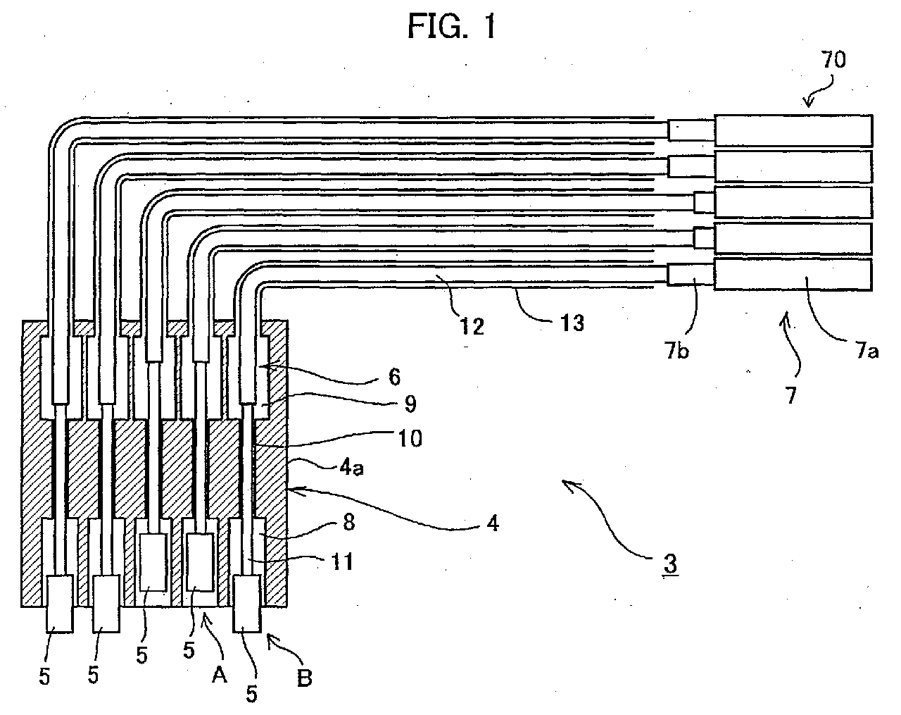
- FIG. 1 shows a cutoff piece taking out mechanism of a wire-cut electric discharge machine according to an embodiment of the present invention.
- the cutoff piece taking out mechanism 3 comprises a takeout head 4 for holding and taking out a cutoff piece from a workpiece, a plurality of permanent magnets 5 for exerting magnetic force to attract and hold the cutoff piece, sliding mechanisms 6 for respectively and independently move the permanent magnets 5 upward and downward, a sliding mechanism driving section 70 comprising actuators for independently actuating the sliding mechanisms 6, and a robot to which the takeout head 4 is attached.
- double-acting air cylinder units 7 each having a cylinder 7a and a piston rod 7b extending from the cylinder 7a are employed as the actuators for actuating the sliding mechanisms 6.
- a head body (housing) 4a of the takeout head 4 is made of non-magnetic material.
- the head body 4a constitutes a cutoff piece motion restricting member for restricting a motion of the cutoff piece held by the permanent magnets 5 relative to a motion of the permanent magnets 5 so as to release the cutoff piece from the permanent magnets 5.
- Magnet accommodation chambers 8 are provided to be opened downward of the head body 4a at a bottom portion of the head body 4a, connection chambers 9 are provided at an upper portion of the head body 4a, and through holes 10 are formed to respectively communicate the magnet accommodation chambers 8 with the connection chambers 9.
- Each of the connection chambers 9 has a through hole to open on an upper surface of the head body 4a.
- a plural sets of accommodating structures for accommodating the permanent magnets 5 and the sliding mechanisms 6 are provided in the head body 4a, each set comprising the magnet accommodation chamber 8, the connection chamber 9 and the through hole 10.
- FIG. 2 shows an arrangement of permanent magnets 5 at the bottom of the takeout head 4 as viewed from the top of the takeout head 4. In this embodiment, twenty five permanent magnets 5 are arranged in a matrix of five rows and five columns.
- the permanent magnets 5 are respectively accommodated in the magnet accommodation chambers 8.
- a support rod 11 is inserted into the through hole 10 and a lower end of the support rod 11 is fixed to an upper end of each permanent magnet 5 and an upper end of the support rod 11 is located in the connection chamber 9 and fixed to an lower end of a flexible wire 12.
- the flexible wire 12 extends out of the takeout head 4 from the upper face of the head body 4a being covered by a flexible tube 13 and is bent and connected to a distal end of the piston rod 7b of the double-acting air cylinder unit 7.
- the reciprocating motion of the double-acting air cylinder unit 7 is controlled by switching flow paths of driving medium by a selector valve.
- a home position of the piston rod 7b the lower end of the permanent magnet 5 is retracted in the magnet accommodation chamber 8 as shown by the reference character A and the magnetic force of the permanent magnet 5 is not exerted on the cutoff piece positioned on a bottom face of the takeout head 4.
- the piston rod 7b extends from the home position, the motion of the piston rod 7b is transmitted by the wire 12 to the sliding rod 11 and the permanent magnet 5 to be moved downwardly relative to the takeout head 4.
- the lower end of the permanent magnet 5 is projected from the bottom face of the takeout head 4, as shown by the reference character B, to attract and hold the cutoff piece by the magnetic force of the permanent magnet 5.
- the magnetic force of the permanent magnet 5 is made ineffective at the bottom face of the takeout head 4 to disable holding the cutout piece.
- FIG. 3 shows the wire-cut electric discharge machine according to the embodiment of the present invention.
- a controller 20 of the wire-cut electric discharge machine comprises a processor (CPU) 21, a memory 22 constituted by ROM and RAM, a display/input section 23 having a display device such as liquid crystal display and CRT and a data input device such as a keyboard on an operation panel, an I/O circuit 24, and axis control circuits 28 for feed axes of X, Y and Z.
- processor CPU
- memory 22 constituted by ROM and RAM
- I/O circuit 24 for feed axes of X, Y and Z.
- Servo amplifiers 29x, 29y and 29z are respectively connected to the axis control circuits 28 and servomotors 30x, 30y and 30z are respectively connected to the servo amplifiers 29x, 29y and 29z.
- the servomotors 30x, 30y and 30z are provided with position/velocity detectors for detecting position and/or velocity of the associated servomotors, and the detected position and/or velocity of the respective servomotors 30x, 30y and 30z are fed back to the axis control circuits 28 and feedback controls of position and/or velocity of the respective axes are performed.
- the servomotors 30x and 30y drive a table for mounting a workpiece in X-Y directions and the servomotor 30y drives an upper wire guide in a Z direction perpendicular to the X and Y axes.
- a present position register for storing present positions of the respective axes based on feedback signals from the position/velocity detectors is provided so that present positions of the respective axes are read from the present position resister.
- additional axes of U, V for moving the upper wire guide in a plane parallel to the X-Y plane may be provided which are not shown in FIG. 3.
- a power supply circuit 25 an actuator control circuit 26 for controlling motion of the actuators and a robot 31 for transferring a cutoff piece held by the takeout head 4 from a takeout position to a release position are connected.
- the processor 21 outputs signals specifying machining conditions of an OFF-time, an ON-time, etc., and machining start/end signals to the power supply circuit 25 through the I/O circuit 24.
- the processor 21 further outputs a takeout command to take out a cutoff piece to the robot 31 through the I/O circuit 24 and receives a motion completion signal from the robot 31.
- the above-described hardware configuration of the controller of the wire-cut electric discharge machine is the same as a conventional controller of the wire-cut electric discharge machine and such conventional controller may be utilized for achieving the wire-cut electric discharge machine of the present invention.
- Magnet numbers #1 to #25 are respectively assigned to the twenty five permanent magnets 5 arranged in a matrix of five rows and five columns.
- the takeout position at which the robot takes out a cutoff piece by the takeout head 4 and the release position to release the cutoff piece taken out from the workpiece, and a motion path from the takeout position to the release position are taught to the robot 31. Further, information designating magnet numbers to be moved for attracting the cutoff piece in accordance with the shape of the cutoff piece is stored in the memory 22 from an operation program.
- FIG. 5 shows the takeout head 4 at the takeout position and positions of the permanent magnets 5 to be actuated in accordance with the shape of the cutoff piece. Additionally referring to FIG. 2, the magnets 5 of the numbers #2, #3, #4, #5, #6, #11, #16, #22 and #23 are positioned right above the cutoff piece 2 as shown in FIG. 5. Thus, the magnet numbers #2-#6, #11, #16, #22 and #23 are designated for this shape of the cutoff piece 2 and stored in the memory 22.
- the processor 21 In taking out the cutoff piece 2, the processor 21 outputs a takeout command to the robot 31. In response to the takeout command, the robot 31 moves the takeout head 4 to the takeout position for taking out the cutoff piece. After positioning the takeout head 4, the robot 31 output a motion completion signal to the controller 20. In receipt of the motion completion signal, the processor 21 reads the magnet numbers stored for the shape of the cutoff piece 2 and outputs commands to move the permanent magnets 5 of the read magnet numbers (e.g. #2-#6, #11, #16, #22 and #23 in the above example) to the actuator control circuit 26.
- the permanent magnets 5 of the read magnet numbers e.g. #2-#6, #11, #16, #22 and #23 in the above example
- the appropriate magnets for exerting the magnetic force to attract only the cutoff piece 2 other than the remaining part of the workpiece 1 are moved downwardly to close to the cutoff piece 2 by several millimeters to attract and hold the cutoff piece 2 by the magnetic force. Since the held cutoff piece 2 are attracted and firmly held by the plurality of permanent magnets 5, an orientation of the cutoff piece 2 is maintained horizontally and is taken out from the workpiece without interfering with the workpiece 1, as shown in FIG. 6.
- the processor 21 After the cutoff piece 2 is taken out as being held by the permanent magnets 5, the processor 21 outputs a remove command to the robot. In receipt of the remove command, the robot 31 moves the takeout head 4 to the releasing position through the taught motion path. Thus, the cutoff piece 2 held by the takeout head 4 is removed from the machining area to the release position sufficiently remote from the machining area. After completing the motion to the release position, the robot outputs a motion completion signal to the controller 20. Upon receipt of the motion completion signal, the processor 21 outputs commands to move the permanent magnets 5 of the read numbers (e.g. #2-#6, #11, #16, #22 and #23 in the above example) upwardly to the actuator control circuit 26.
- the read numbers e.g. #2-#6, #11, #16, #22 and #23 in the above example
- the sliding rods 11 and the permanent magnets 5 are moved upwardly relatively to the head body 4a to lift the cutoff piece 2, and the cutoff piece 2 brought into contact with the bottom face of the head body 4a is prevented from further upward motion. From this state, the sliding rod 11 and the permanent magnets 5 are further moved upwardly to make the magnetic force of the permanent magnets 5 ineffective on the cutoff piece so that the cutoff piece 2 is separated and released from the takeout head 4 to drop, as shown in FIG. 7.
- the double-acting air cylinder units are employed as the actuators for actuating the sliding mechanisms 6 and the reciprocating motion of the double-acting air cylinder unit is transmitted to the sliding mechanism 6 by the wire 12 to move the permanent magnets 5 with the sliding rod 11 upward and downward along one axis.
- single-acting air cylinder units 71 may be employed as shown in FIG.
- the double-acting air cylinder units may be directly connected to the permanent magnets 5 to drive them directly to move upward and downward by the reciprocating motions of the double-acting air cylinder units.
- suction heads 17 with pads 17a as shown in FIG. 9 may be provided in a head body 42a of a takeout head 42 as the attracting means instead of the permanent magnets 5.
- the suction heads 17 are independently operated by valves 16 connected to a vacuum pump.
- the takeout head 4 is attached to a distal end of the robot arm, the attracting head 4 may be attached to a transferring mechanism having two axes motion along a vertical axis (Z-axis) in up and down directions and horizontal axes (X-Y axes) for transferring the takeout head 4 between the takeout position and the release position.
- Z-axis vertical axis
- X-Y axes horizontal axes
Landscapes
- Engineering & Computer Science (AREA)
- Mechanical Engineering (AREA)
- Chemical & Material Sciences (AREA)
- Chemical Kinetics & Catalysis (AREA)
- Electrochemistry (AREA)
- Electrical Discharge Machining, Electrochemical Machining, And Combined Machining (AREA)
Abstract
A wire-cut electric discharge machine capable of taking out a cutoff
piece smoothly upwardly of a workpiece even if the cutoff piece has a
complicated shape, by holding the cutoff piece horizontally not to change
an orientation thereof. The wire-cut electric discharge machine comprises
a cutoff piece taking-out mechanism 3 with a takeout head 4 having a
plurality of permanent magnets 5 for holding the cutoff piece by magnetic
force, and a motion restriction member 4a for restricting motion of the held
cutoff piece relative to the permanent magnets 5. Sliding means 6 for
sliding the plurality of magnets 5 independently to project from and retract
into the motion restricting member 4a are provided, together with
transferring means for transferring the takeout head 4, and selecting means
70 for selecting at least one of the plurality of permanent magnets 5 to exert
magnetic force on the cutoff piece in accordance with a shape of the cutoff
piece. The cutoff piece is held by the takeout head 4 by projecting the
selected permanent magnets 5 from the motion restricting member 4a by
the sliding means 6, and the held cutoff piece is released by retracting the
selected permanent magnets 5 into the motion restricting member 4a by the
sliding means 6.
Description
- The present invention relates to a wire-electric discharge machine having a cutoff piece taking out mechanism for taking out a cutoff piece produced by wire-cut electric discharge machining.
- In a wire-cut electric discharge machine for machining a workpiece by electric discharge generated between a wire electrode and the workpiece by applying electric voltage in-between, there has been arisen a problem how to automatically take out a cutoff piece, which is a product of the electric discharge machining or a waste to be removed, from the workpiece and there has been various proposals for such a problem.
- As devices for holding a cutoff piece and taking out the cutoff piece upwardly, there have been proposed a device for attracting a cutoff piece by suction means (see for example JP 2826357B), a device for attracting a cutoff piece by magnet (permanent magnet or electric magnet, see for example JP 60-242195A, JP 7-67651B). Further, as a device for removing a cutoff piece to be dropped from the workpiece, there are known a device in which the dropped cutoff piece is received by a plate and transferred with the plate by an actuator (see for example JP 2566461B) and a device in which the dropped cutoff piece is received by a basket and transferred by a robot or an actuator (see for example JP 2002-263958A).
- However, cutoff pieces produced by the wire-cut electric discharge machine, one of which is shown in FIG. 4 for example, have various and complicated shapes. In FIG. 4, a
reference numeral 1 denotes a workpiece and areference numeral 2 denotes a cutoff piece cut off from the workpiece by the wire-electric discharge machining. In the device as disclosed in JP 2002-263958A, it is necessary to hold at a center of gravity of the cutoff piece so as not to incline the cutoff piece of a complicated shape in taking out the cutoff piece upwardly, and thus means for calculating a position of the center of gravity of the cutoff piece. Further, even if the position of the center of gravity is calculated, since a suction pad is relatively small, there is a case where the holding position is slightly displaced from the center of gravity in sucking a large cutoff piece to incline the cutoff piece so that the cutoff piece is disable to be smoothly lifted up from the workpiece making interference with the workpiece. - In the device as disclosed in JP 7-67651B employing permanent magnets, it is necessary to fix permanent magnets (magnet holders) at a predetermined arrangement on a base plate by screws in accordance with a shape of a cutoff piece and thus has a difficulty in taking out cutoff pieces of various shapes automatically and efficiently.
- In the device as disclosed in JP 60-242195A employing electromagnets, it is improved to take out cutoff pieces of various shapes automatically and efficiently by selecting appropriate electromagnets in accordance with a shape of cutoff piece to be taken out. However, as inherence of the electromagnets, magnetization of cores of the electromagnets is not released as being used for a long time and has a problem that it is difficult to attract the cutoff piece by magnetize the appropriate electromagnets only in accordance with a shape of a cutoff piece to be taken out.
- Further, in the devices in which a cutoff piece is removed by being dropped from the workpiece as disclosed in JP 2566461B and JP 2002-263958A, a balance of the cutoff piece of complicated shape may be lost and the cutoff piece may make contact with the workpiece to fail in smoothly dropping from the workpiece or in dropping from the workpiece as being caught by the workpiece.
- The present invention enables to take out a cutoff piece smoothly from a workpiece even if the cutoff piece has a complicated shape, by holding the cutoff piece horizontally not to change an orientation of the cutoff piece in taking out the cutoff piece from the workpiece.
- According to an aspect of the present invention, a wire-cut electric discharge machine comprises: a takeout head having a plurality of permanent magnets for holding the cutoff piece by magnetic force and a motion restriction member for restricting motion of the held cutoff piece relative to the permanent magnets; sliding means for sliding the plurality of magnets independently to project from and retract into the motion restricting member; transferring means for transferring the takeout head; selecting means for selecting at least one of the plurality of permanent magnets to exert the magnetic force on the cutoff piece in accordance with a shape of the cutoff piece. The cutoff piece is held by the takeout head by projecting the selected permanent magnets from the motion restricting member by the sliding means, and the held cutoff piece is released by retracting the selected permanent magnets into the motion restricting member by the sliding means.
- The sliding means may comprise support rods respectively connected to the plurality of permanent magnets, independently operating actuators and flexible wires for respectively transmitting motions of the actuators to the support rods.
- The actuators may comprise double-acting air cylinder units.
- Alternatively, the actuators may comprise single-acting air cylinder units. In this case, single-acting motions of the air cylinder units are transmitted to the support rods through the flexible wires, and the sliding means may further comprise springs for urging the plurality of magnets in directions opposite to the single-acting motions of the air cylinders.
- Information designating at least one permanent magnet to be selected may be stored in a controller of the wire-cut electric discharge machine.
- According to another aspect of the present invention, a wire-cut electric discharge machine comprises: a takeout head having a plurality of independently operating suction devices for holding the cutoff piece by suction; transferring means for transferring the takeout head; selecting means for selecting at least one of the plurality of suction means to perform suction on the cutoff piece in accordance with a shape of the cutoff piece. The cutoff piece is held by the takeout head by operating the selected suction means to thereby enable takeout of the cutoff piece from the workpiece.
- Information designating at least one suction means to be selected may be stored in a controller of the wire-cut electric discharge machine.
- According to the present invention, the takeout head holds a cutoff piece by operating selected one or ones of a plurality of permanent magnets or suction devices in accordance with a shape of the cutoff piece so that the cutoff piece is held horizontally to allow the held cutoff piece to be smoothly taken out from the workpiece upwardly even if the cutoff piece has a complicated shape.
-
- FIG. 1 is an elevation view partly in section of a cutoff piece taking out mechanism according to an embodiment of the present invention;
- FIG. 2 is a diagram showing an arrangement of permanent magnets in a takeout head as viewed from top of the takeout head;
- FIG. 3 is a block diagram showing a principal part of a wire-cut electric discharge machine according the embodiment;
- FIG. 4 is a schematic diagram showing an example of a cutoff piece cut out from a workpiece by wire-cut electric discharge machining;
- FIG. 5 is a diagram showing a position of the taking out head for taking out a cutoff piece;
- FIG. 6 is a diagram showing a state where a cutoff piece is took out from the workpiece;
- FIG. 7 is a diagram showing a state where the cutoff piece is released to drop by releasing the magnetic force;
- FIG. 8 is an elevation view partly in section of another cutoff piece taking out mechanism using single-acting air cylinders and springs to exert elastic forces to the permanent magnets; and
- FIG. 9 is an elevation view partly in section of still another cutoff piece taking out mechanism using suction pads as the attracting means.
-
- FIG. 1 shows a cutoff piece taking out mechanism of a wire-cut electric discharge machine according to an embodiment of the present invention. The cutoff piece taking out
mechanism 3 comprises atakeout head 4 for holding and taking out a cutoff piece from a workpiece, a plurality ofpermanent magnets 5 for exerting magnetic force to attract and hold the cutoff piece,sliding mechanisms 6 for respectively and independently move thepermanent magnets 5 upward and downward, a slidingmechanism driving section 70 comprising actuators for independently actuating thesliding mechanisms 6, and a robot to which thetakeout head 4 is attached. In this embodiment, double-actingair cylinder units 7 each having acylinder 7a and apiston rod 7b extending from thecylinder 7a are employed as the actuators for actuating thesliding mechanisms 6. - A head body (housing) 4a of the
takeout head 4 is made of non-magnetic material. In this embodiment, thehead body 4a constitutes a cutoff piece motion restricting member for restricting a motion of the cutoff piece held by thepermanent magnets 5 relative to a motion of thepermanent magnets 5 so as to release the cutoff piece from thepermanent magnets 5. -
Magnet accommodation chambers 8 are provided to be opened downward of thehead body 4a at a bottom portion of thehead body 4a,connection chambers 9 are provided at an upper portion of thehead body 4a, and throughholes 10 are formed to respectively communicate themagnet accommodation chambers 8 with theconnection chambers 9. Each of theconnection chambers 9 has a through hole to open on an upper surface of thehead body 4a. Thus, a plural sets of accommodating structures for accommodating thepermanent magnets 5 and thesliding mechanisms 6 are provided in thehead body 4a, each set comprising themagnet accommodation chamber 8, theconnection chamber 9 and the throughhole 10. FIG. 2 shows an arrangement ofpermanent magnets 5 at the bottom of thetakeout head 4 as viewed from the top of thetakeout head 4. In this embodiment, twenty fivepermanent magnets 5 are arranged in a matrix of five rows and five columns. - The
permanent magnets 5 are respectively accommodated in themagnet accommodation chambers 8. Asupport rod 11 is inserted into the throughhole 10 and a lower end of thesupport rod 11 is fixed to an upper end of eachpermanent magnet 5 and an upper end of thesupport rod 11 is located in theconnection chamber 9 and fixed to an lower end of aflexible wire 12. Theflexible wire 12 extends out of thetakeout head 4 from the upper face of thehead body 4a being covered by aflexible tube 13 and is bent and connected to a distal end of thepiston rod 7b of the double-actingair cylinder unit 7. - The reciprocating motion of the double-acting
air cylinder unit 7 is controlled by switching flow paths of driving medium by a selector valve. In a home position of thepiston rod 7b, the lower end of thepermanent magnet 5 is retracted in themagnet accommodation chamber 8 as shown by the reference character A and the magnetic force of thepermanent magnet 5 is not exerted on the cutoff piece positioned on a bottom face of thetakeout head 4. When thepiston rod 7b extends from the home position, the motion of thepiston rod 7b is transmitted by thewire 12 to thesliding rod 11 and thepermanent magnet 5 to be moved downwardly relative to thetakeout head 4. At the end position of the extending motion of thepiston rod 7b, the lower end of thepermanent magnet 5 is projected from the bottom face of thetakeout head 4, as shown by the reference character B, to attract and hold the cutoff piece by the magnetic force of thepermanent magnet 5. When thepermanent magnet 5 is moved upward to be retracted in themagnet accommodation chamber 8, the magnetic force of thepermanent magnet 5 is made ineffective at the bottom face of thetakeout head 4 to disable holding the cutout piece. The above up and down motions of each of thepermanent magnets 5 is independently performed by the double-actingair cylinder unit 7. - FIG. 3 shows the wire-cut electric discharge machine according to the embodiment of the present invention.
- A
controller 20 of the wire-cut electric discharge machine comprises a processor (CPU) 21, amemory 22 constituted by ROM and RAM, a display/input section 23 having a display device such as liquid crystal display and CRT and a data input device such as a keyboard on an operation panel, an I/O circuit 24, andaxis control circuits 28 for feed axes of X, Y and Z. -
Servo amplifiers axis control circuits 28 andservomotors servo amplifiers servomotors respective servomotors axis control circuits 28 and feedback controls of position and/or velocity of the respective axes are performed. For instance, theservomotors 30x and 30y drive a table for mounting a workpiece in X-Y directions and the servomotor 30y drives an upper wire guide in a Z direction perpendicular to the X and Y axes. In thememory 22, a present position register for storing present positions of the respective axes based on feedback signals from the position/velocity detectors is provided so that present positions of the respective axes are read from the present position resister. Further, additional axes of U, V for moving the upper wire guide in a plane parallel to the X-Y plane may be provided which are not shown in FIG. 3. - To the I/
O circuits 24, apower supply circuit 25, anactuator control circuit 26 for controlling motion of the actuators and arobot 31 for transferring a cutoff piece held by thetakeout head 4 from a takeout position to a release position are connected. Theprocessor 21 outputs signals specifying machining conditions of an OFF-time, an ON-time, etc., and machining start/end signals to thepower supply circuit 25 through the I/O circuit 24. Theprocessor 21 further outputs a takeout command to take out a cutoff piece to therobot 31 through the I/O circuit 24 and receives a motion completion signal from therobot 31. The above-described hardware configuration of the controller of the wire-cut electric discharge machine is the same as a conventional controller of the wire-cut electric discharge machine and such conventional controller may be utilized for achieving the wire-cut electric discharge machine of the present invention. - Selection of the
permanent magnets 5 to attract and hold a cutoff piece in accordance with a shape of the cutoff piece will be described.Magnet numbers # 1 to #25 are respectively assigned to the twenty fivepermanent magnets 5 arranged in a matrix of five rows and five columns. - The takeout position at which the robot takes out a cutoff piece by the
takeout head 4 and the release position to release the cutoff piece taken out from the workpiece, and a motion path from the takeout position to the release position are taught to therobot 31. Further, information designating magnet numbers to be moved for attracting the cutoff piece in accordance with the shape of the cutoff piece is stored in thememory 22 from an operation program. - FIG. 5 shows the
takeout head 4 at the takeout position and positions of thepermanent magnets 5 to be actuated in accordance with the shape of the cutoff piece. Additionally referring to FIG. 2, themagnets 5 of thenumbers # 2, #3, #4, #5, #6, #11, #16, #22 and #23 are positioned right above thecutoff piece 2 as shown in FIG. 5. Thus, the magnet numbers #2-#6, #11, #16, #22 and #23 are designated for this shape of thecutoff piece 2 and stored in thememory 22. - Removal of the
cutoff piece 2 from a machining area will be described. In taking out thecutoff piece 2, theprocessor 21 outputs a takeout command to therobot 31. In response to the takeout command, therobot 31 moves thetakeout head 4 to the takeout position for taking out the cutoff piece. After positioning thetakeout head 4, therobot 31 output a motion completion signal to thecontroller 20. In receipt of the motion completion signal, theprocessor 21 reads the magnet numbers stored for the shape of thecutoff piece 2 and outputs commands to move thepermanent magnets 5 of the read magnet numbers (e.g. #2-#6, #11, #16, #22 and #23 in the above example) to theactuator control circuit 26. Thus, the appropriate magnets for exerting the magnetic force to attract only thecutoff piece 2 other than the remaining part of theworkpiece 1 are moved downwardly to close to thecutoff piece 2 by several millimeters to attract and hold thecutoff piece 2 by the magnetic force. Since the heldcutoff piece 2 are attracted and firmly held by the plurality ofpermanent magnets 5, an orientation of thecutoff piece 2 is maintained horizontally and is taken out from the workpiece without interfering with theworkpiece 1, as shown in FIG. 6. - After the
cutoff piece 2 is taken out as being held by thepermanent magnets 5, theprocessor 21 outputs a remove command to the robot. In receipt of the remove command, therobot 31 moves thetakeout head 4 to the releasing position through the taught motion path. Thus, thecutoff piece 2 held by thetakeout head 4 is removed from the machining area to the release position sufficiently remote from the machining area. After completing the motion to the release position, the robot outputs a motion completion signal to thecontroller 20. Upon receipt of the motion completion signal, theprocessor 21 outputs commands to move thepermanent magnets 5 of the read numbers (e.g. #2-#6, #11, #16, #22 and #23 in the above example) upwardly to theactuator control circuit 26. Thus, the slidingrods 11 and thepermanent magnets 5 are moved upwardly relatively to thehead body 4a to lift thecutoff piece 2, and thecutoff piece 2 brought into contact with the bottom face of thehead body 4a is prevented from further upward motion. From this state, the slidingrod 11 and thepermanent magnets 5 are further moved upwardly to make the magnetic force of thepermanent magnets 5 ineffective on the cutoff piece so that thecutoff piece 2 is separated and released from thetakeout head 4 to drop, as shown in FIG. 7. - The present invention is not limited to the above-described embodiment, and various modifications may be made thereto within the scope of the present invention.
- In the above embodiment, the double-acting air cylinder units are employed as the actuators for actuating the sliding
mechanisms 6 and the reciprocating motion of the double-acting air cylinder unit is transmitted to the slidingmechanism 6 by thewire 12 to move thepermanent magnets 5 with the slidingrod 11 upward and downward along one axis. In place of the double-actingair cylinder units 7, single-actingair cylinder units 71 may be employed as shown in FIG. 8, so that a retracting motion of the single-actingair cylinder unit 71 is transmitted to thepermanent magnet 5 and the slidingrod 11 by theflexible wire 12 to move them upward, and aspring 14 is provided in theconnection chamber 9 of thetakeout head 41 between the upper wall of thehead body 41a and the upper end of the slidingrod 11 so that thepermanent magnet 5 and the slidingrod 11 are moved downward by an elastic force of thespring 14. - Further, the double-acting air cylinder units may be directly connected to the
permanent magnets 5 to drive them directly to move upward and downward by the reciprocating motions of the double-acting air cylinder units. - The permanent magnets are employed as attracting means for attracting and holding the cutoff piece in the above embodiment. Alternatively, suction heads 17 with
pads 17a as shown in FIG. 9 may be provided in ahead body 42a of atakeout head 42 as the attracting means instead of thepermanent magnets 5. The suction heads 17 are independently operated byvalves 16 connected to a vacuum pump. - In the above embodiment, the
takeout head 4 is attached to a distal end of the robot arm, the attractinghead 4 may be attached to a transferring mechanism having two axes motion along a vertical axis (Z-axis) in up and down directions and horizontal axes (X-Y axes) for transferring thetakeout head 4 between the takeout position and the release position.
Claims (7)
- A wire-cut electric discharge machine for cutting off a cutoff piece from a workpiece by electric discharge between a wire electrode and the workpiece, comprising:wherein the cutoff piece is held by said takeout head by projecting the selected permanent magnets from said motion restricting member by said sliding means, and the held cutoff piece is released by retracting the selected permanent magnets into said motion restricting member by said sliding means.a takeout head having a plurality of permanent magnets for holding the cutoff piece by magnetic force and a motion restriction member for restricting motion of the held cutoff piece relative to the permanent magnets;sliding means for sliding said plurality of magnets independently to project from and retract into said motion restricting member;transferring means for transferring said takeout head;selecting means for selecting at least one of said plurality of permanent magnets to exert the magnetic force on the cutoff piece in accordance with a shape of the cutoff piece,
- A wire-cut electric discharge machine according to claim 1, wherein said sliding means comprises support rods respectively connected to the plurality of permanent magnets, independently operating actuators and flexible wires for respectively transmitting motions of the actuators to said support rods.
- A wire-cut electric discharge machine according to claim 2, wherein said actuators comprise double-acting air cylinder units.
- A wire-cut electric discharge machine according to claim 2, wherein said actuators comprise single-acting air cylinder units and single-acting motions of said air cylinder units are transmitted to said support rods through said flexible wires, and said sliding means further comprises springs for urging said plurality of magnets in directions opposite to the single-acting motions of said air cylinders.
- A wire-cut electric discharge machine according to claim 1, wherein information designating at least one permanent magnet to be selected is stored in a controller of the wire-cut electric discharge machine.
- A wire-cut electric discharge machine for cutting off a cutoff piece from a workpiece by electric discharge between an wire electrode and the workpiece, comprising:wherein the cutoff piece is held by said takeout head by operating the selected suction means to thereby enable takeout of the cutoff piece from the workpiece.a takeout head having a plurality of independently operating suction devices for holding the cutoff piece by suction;transferring means for transferring said takeout head;selecting means for selecting at least one of said plurality of suction means to perform suction on the cutoff piece in accordance with a shape of the cutoff piece,
- A wire-cut electric discharge machine according to claim 1, wherein information designating at least one suction means to be selected is stored in a controller of the wire-cut electric discharge machine.
Applications Claiming Priority (2)
| Application Number | Priority Date | Filing Date | Title |
|---|---|---|---|
| JP2004017784 | 2004-01-27 | ||
| JP2004017784A JP2005211990A (en) | 2004-01-27 | 2004-01-27 | Wire-cut electric discharge machine |
Publications (1)
| Publication Number | Publication Date |
|---|---|
| EP1559495A2 true EP1559495A2 (en) | 2005-08-03 |
Family
ID=34650750
Family Applications (1)
| Application Number | Title | Priority Date | Filing Date |
|---|---|---|---|
| EP05250235A Withdrawn EP1559495A2 (en) | 2004-01-27 | 2005-01-18 | Wire-cut electric discharge machine |
Country Status (4)
| Country | Link |
|---|---|
| US (1) | US7009133B2 (en) |
| EP (1) | EP1559495A2 (en) |
| JP (1) | JP2005211990A (en) |
| CN (1) | CN1647882A (en) |
Families Citing this family (8)
| Publication number | Priority date | Publication date | Assignee | Title |
|---|---|---|---|---|
| ATE517705T1 (en) * | 2007-06-30 | 2011-08-15 | Trumpf Werkzeugmaschinen Gmbh | MACHINE TOOL AND METHOD FOR EXHAUSTING A PART OF A WORKPIECE |
| JP5199447B1 (en) * | 2011-12-09 | 2013-05-15 | ファナック株式会社 | Wire electrical discharge machine with rotating shaft |
| JP5752196B2 (en) | 2013-09-03 | 2015-07-22 | ファナック株式会社 | Program creation device for wire electric discharge machine |
| JP6464115B2 (en) * | 2016-05-25 | 2019-02-06 | ファナック株式会社 | Wire electrical discharge machining system |
| JP6680660B2 (en) * | 2016-10-18 | 2020-04-15 | ファナック株式会社 | Wire electric discharge machine |
| JP6599532B1 (en) * | 2018-10-12 | 2019-10-30 | 株式会社ソディック | Core mover for wire cut electric discharge machine |
| WO2023006777A1 (en) * | 2021-07-26 | 2023-02-02 | Neolix | Device for electrical discharge machining of a plurality of bars, comprising a facility for recovering machined bar segments |
| FR3125448B1 (en) * | 2021-07-26 | 2023-10-06 | Neolix | device for electroerosion machining of a plurality of bars, comprising equipment for receiving the machined bar segments |
Family Cites Families (12)
| Publication number | Priority date | Publication date | Assignee | Title |
|---|---|---|---|---|
| JPS60242195A (en) | 1984-05-12 | 1985-12-02 | 株式会社新来島どっく | Selective controller for lifting-magent for carrying out steel plate |
| CH664917A5 (en) * | 1985-12-12 | 1988-04-15 | Charmilles Technologies | METHOD FOR RETAINING THE DETACHED PARTS OF A DRAFT BY ELECTROEROSION, AND DEVICE FOR ITS PRODUCTION. |
| JPH0767651B2 (en) | 1987-01-26 | 1995-07-26 | 三菱電機株式会社 | Cutting work removal device |
| JP2566461B2 (en) | 1989-05-24 | 1996-12-25 | ファナック株式会社 | Core removal device |
| JPH0379226A (en) * | 1989-08-22 | 1991-04-04 | Fanuc Ltd | Core remover |
| JP2826357B2 (en) | 1989-12-26 | 1998-11-18 | ファナック株式会社 | Core removal device for wire electric discharge machine |
| JP2586955B2 (en) * | 1990-01-19 | 1997-03-05 | ファナック株式会社 | Core removal method |
| JPH03256617A (en) * | 1990-03-07 | 1991-11-15 | Fanuc Ltd | Core holding device |
| JPH03287314A (en) * | 1990-04-05 | 1991-12-18 | Fanuc Ltd | Cut-out piece removing method in electric discharge machining |
| DE69103716T2 (en) * | 1990-10-08 | 1995-02-09 | Mitsubishi Electric Corp | Electrical erosion device with wire electrode. |
| JPH06238520A (en) * | 1993-02-15 | 1994-08-30 | Makino Milling Mach Co Ltd | Core processing equipment for wire electric discharge machine |
| JP3576988B2 (en) * | 2001-03-09 | 2004-10-13 | ファナック株式会社 | Wire electric discharge machine |
-
2004
- 2004-01-27 JP JP2004017784A patent/JP2005211990A/en active Pending
-
2005
- 2005-01-18 EP EP05250235A patent/EP1559495A2/en not_active Withdrawn
- 2005-01-18 US US11/036,394 patent/US7009133B2/en not_active Expired - Fee Related
- 2005-01-27 CN CN200510004817.7A patent/CN1647882A/en active Pending
Also Published As
| Publication number | Publication date |
|---|---|
| US20050161441A1 (en) | 2005-07-28 |
| CN1647882A (en) | 2005-08-03 |
| US7009133B2 (en) | 2006-03-07 |
| JP2005211990A (en) | 2005-08-11 |
Similar Documents
| Publication | Publication Date | Title |
|---|---|---|
| US7438857B2 (en) | Liquid handling tool having porous plunger | |
| US7009133B2 (en) | Wire-cut electric discharge machine | |
| US20090297327A1 (en) | Apparatus and method for transferring samples from a source to a target | |
| JP2006329986A (en) | Device and method for transferring sample from source to target | |
| EP1493036B1 (en) | Robotically manipulable sample handling tool | |
| JPH11340695A (en) | Assembly equipment | |
| CN108621190B (en) | Method and device for monitoring the state of a vacuum suction of a gripping device | |
| JPWO2016017029A1 (en) | Component mounting method and component mounting apparatus | |
| JP4715814B2 (en) | Seat extending apparatus and seat extending method | |
| US7249529B2 (en) | Robotically manipulable sample handling tool | |
| JP2004241595A (en) | Component mounting machine | |
| JPS6140131B2 (en) | ||
| JP2020172016A (en) | Pallet device corresponding to various types, control system of pallet device corresponding to various types, displacement regulation mechanism, and copying mechanism | |
| JP2005288550A (en) | Precision grinding apparatus and precision grinding method | |
| JP4670843B2 (en) | Seat extending apparatus and seat extending method | |
| JPH0423717A (en) | Electronic parts supply device | |
| CN223534334U (en) | Be used for robot unloading wobble plate mechanism | |
| JP4869999B2 (en) | Work support device | |
| JP7437487B1 (en) | Work supply system, work supply method and work supply program | |
| JP2001252894A (en) | Multi-spindle drilling machine | |
| JP7146525B2 (en) | Stage equipment and bonding equipment | |
| JPH02231800A (en) | Mounting device for electronic component | |
| JP3116848B2 (en) | Chip feeder | |
| JP2025181679A (en) | Component alignment device, component mounting system, component alignment method, and component mounting method | |
| JPH08318481A (en) | Micro manipulator driving device |
Legal Events
| Date | Code | Title | Description |
|---|---|---|---|
| PUAI | Public reference made under article 153(3) epc to a published international application that has entered the european phase |
Free format text: ORIGINAL CODE: 0009012 |
|
| AK | Designated contracting states |
Kind code of ref document: A2 Designated state(s): AT BE BG CH CY CZ DE DK EE ES FI FR GB GR HU IE IS IT LI LT LU MC NL PL PT RO SE SI SK TR |
|
| AX | Request for extension of the european patent |
Extension state: AL BA HR LV MK YU |
|
| STAA | Information on the status of an ep patent application or granted ep patent |
Free format text: STATUS: THE APPLICATION HAS BEEN WITHDRAWN |
|
| 18W | Application withdrawn |
Effective date: 20070111 |