EP1559211B1 - Method and device for establishing links in an ad hoc wireless system - Google Patents
Method and device for establishing links in an ad hoc wireless system Download PDFInfo
- Publication number
- EP1559211B1 EP1559211B1 EP03809938A EP03809938A EP1559211B1 EP 1559211 B1 EP1559211 B1 EP 1559211B1 EP 03809938 A EP03809938 A EP 03809938A EP 03809938 A EP03809938 A EP 03809938A EP 1559211 B1 EP1559211 B1 EP 1559211B1
- Authority
- EP
- European Patent Office
- Prior art keywords
- time slot
- link
- mobile node
- node
- slot
- Prior art date
- Legal status (The legal status is an assumption and is not a legal conclusion. Google has not performed a legal analysis and makes no representation as to the accuracy of the status listed.)
- Expired - Fee Related
Links
- 238000000034 method Methods 0.000 title claims description 126
- 238000004891 communication Methods 0.000 claims description 120
- 230000000977 initiatory effect Effects 0.000 claims description 29
- 238000012790 confirmation Methods 0.000 claims description 15
- 230000008569 process Effects 0.000 description 85
- KFZUDNZQQCWGKF-UHFFFAOYSA-M sodium;4-methylbenzenesulfinate Chemical compound [Na+].CC1=CC=C(S([O-])=O)C=C1 KFZUDNZQQCWGKF-UHFFFAOYSA-M 0.000 description 44
- UBAXRAHSPKWNCX-UHFFFAOYSA-N diallyl trisulfide Chemical compound C=CCSSSCC=C UBAXRAHSPKWNCX-UHFFFAOYSA-N 0.000 description 21
- 230000005540 biological transmission Effects 0.000 description 20
- 238000012545 processing Methods 0.000 description 20
- 238000010586 diagram Methods 0.000 description 16
- 238000010295 mobile communication Methods 0.000 description 16
- 230000008859 change Effects 0.000 description 15
- 238000013459 approach Methods 0.000 description 13
- 238000001514 detection method Methods 0.000 description 8
- 230000007704 transition Effects 0.000 description 8
- 230000011664 signaling Effects 0.000 description 7
- 230000004044 response Effects 0.000 description 6
- 238000012360 testing method Methods 0.000 description 5
- 238000012217 deletion Methods 0.000 description 4
- 230000037430 deletion Effects 0.000 description 4
- 238000007726 management method Methods 0.000 description 4
- 238000012986 modification Methods 0.000 description 4
- 230000004048 modification Effects 0.000 description 4
- 238000012913 prioritisation Methods 0.000 description 4
- 230000008901 benefit Effects 0.000 description 3
- 230000003111 delayed effect Effects 0.000 description 3
- 238000005259 measurement Methods 0.000 description 3
- 230000007246 mechanism Effects 0.000 description 3
- 230000003071 parasitic effect Effects 0.000 description 3
- 108700026140 MAC combination Proteins 0.000 description 2
- 125000004122 cyclic group Chemical group 0.000 description 2
- 230000007423 decrease Effects 0.000 description 2
- 230000001419 dependent effect Effects 0.000 description 2
- 238000009472 formulation Methods 0.000 description 2
- 239000000203 mixture Substances 0.000 description 2
- 230000000737 periodic effect Effects 0.000 description 2
- 238000012546 transfer Methods 0.000 description 2
- 238000012795 verification Methods 0.000 description 2
- 230000009471 action Effects 0.000 description 1
- 230000003044 adaptive effect Effects 0.000 description 1
- 230000002457 bidirectional effect Effects 0.000 description 1
- 230000015556 catabolic process Effects 0.000 description 1
- 239000003086 colorant Substances 0.000 description 1
- 238000010835 comparative analysis Methods 0.000 description 1
- 238000004590 computer program Methods 0.000 description 1
- 230000003247 decreasing effect Effects 0.000 description 1
- 238000006731 degradation reaction Methods 0.000 description 1
- 230000001934 delay Effects 0.000 description 1
- 238000005562 fading Methods 0.000 description 1
- 230000007774 longterm Effects 0.000 description 1
- 238000005457 optimization Methods 0.000 description 1
- 230000002250 progressing effect Effects 0.000 description 1
- 238000005204 segregation Methods 0.000 description 1
Images


Classifications
-
- H—ELECTRICITY
- H04—ELECTRIC COMMUNICATION TECHNIQUE
- H04B—TRANSMISSION
- H04B7/00—Radio transmission systems, i.e. using radiation field
- H04B7/02—Diversity systems; Multi-antenna system, i.e. transmission or reception using multiple antennas
- H04B7/04—Diversity systems; Multi-antenna system, i.e. transmission or reception using multiple antennas using two or more spaced independent antennas
- H04B7/0491—Diversity systems; Multi-antenna system, i.e. transmission or reception using multiple antennas using two or more spaced independent antennas using two or more sectors, i.e. sector diversity
-
- H—ELECTRICITY
- H04—ELECTRIC COMMUNICATION TECHNIQUE
- H04B—TRANSMISSION
- H04B7/00—Radio transmission systems, i.e. using radiation field
- H04B7/24—Radio transmission systems, i.e. using radiation field for communication between two or more posts
- H04B7/26—Radio transmission systems, i.e. using radiation field for communication between two or more posts at least one of which is mobile
- H04B7/2643—Radio transmission systems, i.e. using radiation field for communication between two or more posts at least one of which is mobile using time-division multiple access [TDMA]
- H04B7/2656—Radio transmission systems, i.e. using radiation field for communication between two or more posts at least one of which is mobile using time-division multiple access [TDMA] for structure of frame, burst
-
- H—ELECTRICITY
- H04—ELECTRIC COMMUNICATION TECHNIQUE
- H04J—MULTIPLEX COMMUNICATION
- H04J3/00—Time-division multiplex systems
- H04J3/16—Time-division multiplex systems in which the time allocation to individual channels within a transmission cycle is variable, e.g. to accommodate varying complexity of signals, to vary number of channels transmitted
- H04J3/1694—Allocation of channels in TDM/TDMA networks, e.g. distributed multiplexers
-
- H—ELECTRICITY
- H04—ELECTRIC COMMUNICATION TECHNIQUE
- H04L—TRANSMISSION OF DIGITAL INFORMATION, e.g. TELEGRAPHIC COMMUNICATION
- H04L1/00—Arrangements for detecting or preventing errors in the information received
- H04L1/004—Arrangements for detecting or preventing errors in the information received by using forward error control
- H04L1/0041—Arrangements at the transmitter end
-
- H—ELECTRICITY
- H04—ELECTRIC COMMUNICATION TECHNIQUE
- H04L—TRANSMISSION OF DIGITAL INFORMATION, e.g. TELEGRAPHIC COMMUNICATION
- H04L1/00—Arrangements for detecting or preventing errors in the information received
- H04L1/004—Arrangements for detecting or preventing errors in the information received by using forward error control
- H04L1/0056—Systems characterized by the type of code used
- H04L1/0061—Error detection codes
-
- H—ELECTRICITY
- H04—ELECTRIC COMMUNICATION TECHNIQUE
- H04L—TRANSMISSION OF DIGITAL INFORMATION, e.g. TELEGRAPHIC COMMUNICATION
- H04L1/00—Arrangements for detecting or preventing errors in the information received
- H04L1/20—Arrangements for detecting or preventing errors in the information received using signal quality detector
- H04L1/203—Details of error rate determination, e.g. BER, FER or WER
-
- H—ELECTRICITY
- H04—ELECTRIC COMMUNICATION TECHNIQUE
- H04W—WIRELESS COMMUNICATION NETWORKS
- H04W40/00—Communication routing or communication path finding
- H04W40/02—Communication route or path selection, e.g. power-based or shortest path routing
- H04W40/04—Communication route or path selection, e.g. power-based or shortest path routing based on wireless node resources
- H04W40/06—Communication route or path selection, e.g. power-based or shortest path routing based on wireless node resources based on characteristics of available antennas
-
- H—ELECTRICITY
- H04—ELECTRIC COMMUNICATION TECHNIQUE
- H04W—WIRELESS COMMUNICATION NETWORKS
- H04W72/00—Local resource management
- H04W72/02—Selection of wireless resources by user or terminal
-
- H—ELECTRICITY
- H04—ELECTRIC COMMUNICATION TECHNIQUE
- H04W—WIRELESS COMMUNICATION NETWORKS
- H04W72/00—Local resource management
- H04W72/12—Wireless traffic scheduling
-
- H—ELECTRICITY
- H04—ELECTRIC COMMUNICATION TECHNIQUE
- H04W—WIRELESS COMMUNICATION NETWORKS
- H04W74/00—Wireless channel access
- H04W74/08—Non-scheduled access, e.g. ALOHA
- H04W74/0833—Random access procedures, e.g. with 4-step access
- H04W74/0841—Random access procedures, e.g. with 4-step access with collision treatment
- H04W74/085—Random access procedures, e.g. with 4-step access with collision treatment collision avoidance
-
- H—ELECTRICITY
- H04—ELECTRIC COMMUNICATION TECHNIQUE
- H04W—WIRELESS COMMUNICATION NETWORKS
- H04W76/00—Connection management
- H04W76/10—Connection setup
-
- H—ELECTRICITY
- H04—ELECTRIC COMMUNICATION TECHNIQUE
- H04W—WIRELESS COMMUNICATION NETWORKS
- H04W84/00—Network topologies
- H04W84/18—Self-organising networks, e.g. ad-hoc networks or sensor networks
-
- H—ELECTRICITY
- H04—ELECTRIC COMMUNICATION TECHNIQUE
- H04W—WIRELESS COMMUNICATION NETWORKS
- H04W24/00—Supervisory, monitoring or testing arrangements
Definitions
- the present invention relates to the field of communications, and more particularly, to a network of mobile communication systems operating with directional antennas.
- Time division multiple access is one example of an access scheme used for establishing communication links between wireless mobile communication systems. Communication links between the wireless mobile communication systems are established within a series of time frames. Each time frame is divided into time slots, with each wireless mobile communication system being assigned at least one time slot.
- An omni-directional antenna is typically used by a wireless mobile communication system so that information transmitted by one mobile communication system is received by all the other mobile communication systems.
- the mobile communication systems When the mobile communication systems are operating at a fixed frequency, they must take turns transmitting within their respective time slots to prevent channel interference.
- a directional antenna may be used.
- the directional antenna provides an increased antenna gain in a desired area that is limited in coverage while decreasing the antenna gain towards the remaining area.
- Document US6317436 discloses a method and system for managing communication resources between nodes in a network, and more particularly to a dynamic distributed multichannel time division multiple access (TDMA) slot assignment method is presented.
- the method and apparatus include a set of higher level heuristics that enable the wireless channel access scheme to address predetermined characteristics of the wireless channel access system. These predetermined heuristics include using bootstrap slots, adaptive broadcast cycles, channelized neighborhoods, standby slots, speculation slots, neighbor segregation, hard circuits, and soft circuits.
- Document EP0682425 discloses a communication method including the retransmission of signaling messages that data terminals (e.g., modems) might exchange prior to exchanging user data, wherein it is controlled by arranging a data terminal that receives multiple copies of the same signaling message so that it saves only the first copy thereof, but transmits a response to the sending terminal following receipt of each such copy.
- the sending terminal terminates its transmission of the signaling message upon receipt of a response from the receiving terminal.
- Document WO0239668 discloses an apparatus, a method, and a computer program product for effective communication routing of unicast and broadcast data traffic in wireless ad-hoc networks are presented.
- the routing technique separates the signaling and data transmission portions of data frame such that the length of the signaling portion is independent of the length of the data portion.
- reservations are able to be performed and confirmed, while the data portion also includes a reservation confirmation portion which allows reservations made in during the signaling portion of the frame to be confirmed immediately prior to transmission of the data.
- the present invention also provides a mechanism for dynamically adjusting reservations.
- Document WO 02063836 discloses a data communication system and a method for use in a data communication system is disclosed.
- the system comprises a plurality of nodes provided with means for wireless data communication.
- At least one directed wireless communication link (DCHB) can be formed between a node and another node for data communication.
- control information is generated, said information associating with at least one node of the plurality of nodes.
- Said control information includes at least a capacity parameter that associates with the capacity of said at least one node.
- Data communications between the nodes are scheduled based on said control information and data is communicated between the nodes via said at least one directed link based on said scheduling.
- Document WO 01/28170 discloses a scheduling protocol according to which scheduling packets are exchanged among neighboring nodes of a computer network.
- the scheduling packets include descriptions of a transmitting node's 2-hop neighborhood within the computer network, and nodes are able to determine transmission schedules from information received via said scheduling packets. Transmission schedules may be determined, at least in part, because nodes advertise their availability using the scheduling packets. The identification of reserved communication times and/or channels is made after eliminating any conflicting scheduled transmissions for those communication times and/or channels.
- WO 02/063836 discloses communication between nodes in a network based on a combination of TDMA and space division multiple access (SDMA).
- TDMA is used to define the time slot allocation s for transmissions
- SDMA defines the allocation of transmission resources such that data associated with more than a single transmission may be carried in a single time slot.
- U.S. Patent No. 5, 767, 807 to Pritchett discloses phased array antennas being used for establishing communication links within a network of wireless communication systems.
- the phased array antenna includes parasitic elements for selectively controlling the antenna pattern.
- the phased array antenna radiates an omni-directional signal when all of the parasitic elements are in a high impedance state, and radiates a directional signal when a selected number of parasitic elements are placed in a lower impedance state in response to switching circuits.
- the Pritchett '807 patent discloses the acquisition, by a fixed initiating wireless communication system from a fixed receiving wireless communication system, of a list of the wireless communication systems operating in the network and a corresponding respective time slot list for each wireless communication system. A table is then created based upon the list for scheduling time slots among the wireless communication systems.
- Scheduling time slots for wireless communication systems operating with directional antennas, particularly when the wireless communication systems are mobile, is complex.
- mobile communication systems are continuously entering into and dropping out of the network. Furthermore, reliable confirmation messages are needed.
- a wireless communication network including a plurality of mobile nodes each including a transceiver, a directional antenna, e.g. a phased array antenna, connected to the transceiver, and a controller connected to the transceiver.
- the controller schedules a respective semi-permanent time slot for each time frame to establish a communication link with each neighboring mobile node and leaving at least one available time slot in each time frame, and schedules the at least one available time slot to also serve the communication link with a neighboring mobile node based upon link communications demand.
- An initiating mobile node transmits a request for time slots to the receiving mobile node, which transmits a reply to the initiating mobile node.
- the initiating mobile node transmits a confirmation to the receiving mobile node, and the receiving mobile node transmits the reply again if the confirmation is not received.
- the receiving mobile node may transmit an acknowledgment to the initiating mobile node, and the initiating mobile node transmits the confirmation again if the acknowledgment is not received.
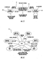
- a wireless mobile communication network 10 comprises a plurality of wireless mobile nodes 12a-12h .
- Each mobile node 12a-12h comprises a transceiver 14 , a directional antenna 16 connected to the transceiver, and a controller 18 connected to the transceiver.
- the controller 18 includes a semi-permanent time slot unit 18a for scheduling a respective semi-permanent time slot for each time frame for establishing a communication link with each neighboring mobile node while leaving at least one available time slot in each time frame.
- An available time slot unit 18b schedules the at least one available time slot to also serve the communication link with a neighboring mobile node based upon link communications demand.
- the controller 18 includes an antenna aiming unit 18c for aiming the directional antenna toward each neighboring mobile node during communication therewith.
- the semi-permanent time slot unit 18a may initiate one or more semi-permanent time slot requests for respective time frames to establish the communication link with each neighboring mobile node and leaving at least one available time slot in each time frame, while processing multiple received semi-permanent time slot requests from neighboring mobile nodes.
- the available time slot unit 18b may initiate one or more available time slot request to also serve the communication link with the neighboring mobile node based upon link communications demand, while processing multiple received available time slot requests from neighboring mobile nodes.
- a node can have one or more pending demand available requests and semi-permanent requests that it initiated while processing multiple received requests. This may sometimes result in temporarily allocating a given time slot to more than one neighbor. However, this conflict may be eliminated by confirmation messages which indicate the selection of one neighbor node for the time slot, as is discussed in more detail below.
- Reliable confirmation messages may be provided with a couple of different approaches.
- An initiating mobile node transmits a request for time slots to the receiving mobile node, which transmits a reply to the initiating mobile node.
- the initiating mobile node transmits a confirmation to the receiving mobile node, and the receiving mobile node transmits the reply again if the confirmation is not received.
- the receiving mobile node may transmit an acknowledgment to the initiating mobile node, and the initiating mobile node transmits the confirmation again if the acknowledgment is not received.
- the controller 18 waits a time period to resend another request upon simultaneously sending a request to an other mobile node and receiving a request from the other mobile node without receiving a corresponding reply. During this time period, incoming time slot requests may be processed. After the period ends, a new request may be sent to the other node if no request was already received from that node or if no time slot allocation was made to that node. If a delayed request reaches the front of the queue, the controller 18 checks to see if a time slot allocation has already been made to that node. If so, the delayed request is discarded. Also, if the request is destined for a node that is no longer a neighbor by the time the request reaches the front of the queue, the delayed request is discarded.
- An interference detection unit 18d is included to detect interference in time slots for communication with neighboring mobile nodes.
- the controller 18 coordinates the scheduling of time slots based upon detected interference.
- the interference detection unit 18d may measure a signal-to-interference ratio and/or a packet error rate.
- the packet error rate may be based upon cyclic redundancy check (CRC) failures.
- the interference detection unit 18d may compare detected interference to a threshold.
- the controller switches an order of communication between nodes for a given time slot based upon detected interference, and may also coordinate scheduling of new time slots based upon detected interference after switching the order of communication.
- a traffic coordination unit 18e coordinates communication with each neighboring mobile node by allocating time slots to the time slot unit based upon link communications demand.
- the controller 18 coordinates the scheduling of time slots based upon based upon allocated time slots.
- the traffic coordination unit 18e may allocate a bulk set of time slots based upon an increased link communications demand, and/or may request a bulk set of time slots from neighboring mobile nodes based upon an increased link communications demand. Also, the traffic coordination unit 18e may increase a maximum number of time slots, reallocate time slots, and/or allocate half time slots based upon increased link communications demand.
- Such increased link communications demand may include streaming video and/or high rate sensor data.
- the wireless mobile nodes 2a-12h are operating in a mobile environment. These systems may be ground based and/or airborne, whereby they are continuously entering into and dropping out of the network 10.
- the directional antenna 16 may be a phased array, a dish or horn antennas, for example. Transmission via a directional antenna 16 enables the RF signal to be focused in a desired direction.
- additional communication links may be established between other wireless communication systems within the same scheduled semi-permanent time slot. This is illustrated by communication link 27 operating in time slot 1 between mobile nodes 12c and 12e , and communication link 29 also operating in time slot 1 between mobile nodes 12a and 12b , as best illustrated in FIG. 1 .
- This feature of the present invention advantageously allows the resources of the wireless mobile communication network 10 to be better utilized.
- the controller 18 limits the number of communication links for each wireless mobile node 12a-12h within each time frame based upon a total number of time slots within the frame.
- the advantage of limiting the number of communication links to a fraction of the total number of time slots within the time frame significantly simplifies the scheduling of time slots with neighboring nodes.
- the number of communication links for each wireless mobile node 12a-12h within each time frame is less than or equal to N, and the total number of time slots within each frame is greater than or equal to 2N-1.
- this type of distributed scheduling avoids conflicts.
- Distributed scheduling allows any two pair of wireless mobile nodes, such as 12a and 12b, for example, to schedule a semi-permanent time slot without having to communicate with any other wireless mobile node.
- the controller 18 may prioritize the communication links and drop one of the communication links based upon the prioritization for making available a semi-permanent time slot for establishing a communication link with a new neighboring mobile node. Prioritization of the communication links will be addressed in greater detail below. In addition, the controller 18 may also prioritize the communication links and schedule the at least one available time slot based upon this prioritization.
- the controller 18 may also schedule one of the semi-permanent time slots as an available time slot if a number of the communication links is less than N. This advantageously supports communication link demands on an as needed basis for the existing communication links. However, the controller 18 may reschedule the demand assigned time slot back to a semi-permanent time slot if the number of the communication links is again equal to N, as will also be discussed in greater detail below.
- Each communication link is formed by an initiating mobile node, such as node 12a , and a receiving mobile node, such as node 12b , and the initiating mobile node transmits a list of available semi-permanent time slots to the receiving mobile node.
- the receiving mobile node 12b then transmits selection of one of the semi-permanent time slots to the initiating mobile node.
- the initiating mobile node 12a then confirms selection of the selected semi-permanent time slot to the receiving mobile node.
- Each mobile node may further comprise an omni-directional antenna 20 connected to the transceiver 14 for exchanging positional information with other neighboring mobile nodes.
- Other information that may be exchanged includes resource requirements and detection of the presence of a potential new neighbor node.
- the phased array antenna 16 may simultaneously generate multiple antenna beams, wherein the controller 18 aims the phased array antenna to multiple neighboring mobile nodes within a scheduled semi-permanent time slot.
- the interference detection unit 18d detects and avoids interference for collinear node pairs within the beamwidth and allocated the same time slot. For example, referring to Fig. 1 , nodes 12a and 12e transmitting to nodes 12b and 12c , respectively during their half of the same assigned time slot 1. With wide enough antenna beamwidths, both nodes 12b and 12c may simultaneously hear transmissions from both nodes 12a and 12e .
- the interference detection unit 18d may measure the Signal-to-Interference Ratio (SINR) at the physical layer during time slot usage. Alternatively, the packet error rate can be measured at the link layer based upon CRC check failures. If these measurements violate a specified threshold, the slot may be declared bad.
- SINR Signal-to-Interference Ratio
- the traffic coordination unit 18e manages unbalanced traffic loads that may be generated by streaming video or high rate sensor data. Coordination mechanisms are provided to permit each half-duplex link to allocate a time slot in any Tx/Rx split of traffic. Also, the maximum number of time slots may be increased to a number above the minimum to create more demand time slots. Subslotting would permit an effective increase or decrease in the maximum number of time slots as nodes may "steal" subslots from a semi-permanent allocated time slot to reallocate to a demand time slot.
- a reservation protocol could be used together with link scheduling procedures to indicate allocation of resources for a high rate stream at each node along a path from a source to a destination node by requesting and allocating a bulk set of time slots and/or subslots at each node along the path to accommodate the high rate stream.
- link scheduling procedures to indicate allocation of resources for a high rate stream at each node along a path from a source to a destination node by requesting and allocating a bulk set of time slots and/or subslots at each node along the path to accommodate the high rate stream.
- For reserved resources separate queues and a queue service discipline may be necessary to insure that the capacity required by the stream is delivered.
- the invention is also directed to a method for establishing communication links for a plurality of mobile nodes 12a-12h , with each mobile node comprising a transceiver 14, a phased array antenna 16 connected to the transceiver, and a controller 18 connected to the transceiver.
- the method comprises for each mobile node 12a-12h scheduling a respective semi-permanent time slot for each time frame to establish a communication link with a neighboring mobile node and leaving at least one available time slot in each time frame.
- the at least one available time slot is preferably scheduled to serve the communication link with a neighboring mobile node based upon link communications demand.
- the phased array antenna 16 is aimed toward each neighboring mobile node 12a-12h during communication therewith.
- Each time frame may have up to N semi-permanent time slots and at least 2N-1 available time slots.
- the method may also include initiating one or more semi-permanent time slot requests for respective time frames to establish a communication link with each neighboring mobile node and leaving at least one available time slot in each time frame, while processing multiple received semi-permanent time slot requests from neighboring mobile nodes, and initiating at least one available time slot request to also serve the communication link with a neighboring mobile node based upon link communications demand, while processing multiple received available time slot requests from neighboring mobile nodes.
- the directional/phased array antenna 16 is aimed toward each neighboring mobile node 12a-12h during communication therewith, interference is detected in time slots for communication with neighboring mobile nodes, and the scheduling of new time slots is coordinated based upon detected interference.
- the interference detection unit 18d may measure a signal-to-interference ratio and/or a packet error rate. The packet error rate may be based upon cyclic redundancy check (CRC) failures. Also, the interference detection unit 18d may compare detected interference to a threshold.
- the controller 18 switches an order of communication between nodes for a given time slot based upon detected interference, and may also coordinate scheduling of new time slots based upon detected interference after switching the order of communication.
- communication with each neighboring mobile node 12a-12h may be coordinated by allocating time slots for scheduling based upon link communications demand.
- the method further includes having each node prioritize the communication links and drop one of the communication links based upon the prioritization for making available a semi-permanent time slot for establishing a communication link with a new neighboring mobile node.
- an available time slot that is currently scheduled to serve a particular communication link may be reassigned to another communication link based on link demand. This advantageously allows any mobile node to accommodate variations in communication link demands.
- the directional antenna 16 is a phased array antenna.
- a phased array antenna 16 includes a plurality of antenna elements and respective phase shifters that can be adjusted for producing a steerable antenna beam in a desired direction.
- the phased array antenna 16 steers or scans the antenna pattern without physically moving the antenna.
- the wireless mobile communication network 10 there is a single frequency band that is a high data rate channel that is shared by all the wireless mobile nodes 12a-12h . This type of transmission channel is time shared between all the wireless mobile nodes 12a-12h for both transmit and receive. All transmission slots are scheduled in advance.
- This overhead channel can be used for node discovery, net entry, and exchange of various other data link control overhead information including resource requests.
- This overhead channel is provided via an omni-directional antenna 20 .
- Good global timing reference is also known at all nodes.
- the terms wireless mobile nodes and wireless mobile communications systems 12a-12h are interchangeable throughout the following discussion.
- the wireless mobile communication network 10 also includes the capability for locating and tracking mobile nodes so that the phased array antennas 16 can be pointed accurately when a scheduled time slot is available. As noted above, a detailed discussion on the pointing/tracking will not be provided herein.
- phased array antennas 16 have zero beamwidth. This assumption will be relaxed later. Consequently, we can assume that a transmission by a given mobile node will be received only by the neighbor mobile node to which it is attempting to transmit. This allows a less restrictive set of constraints on the scheduling of time slots. Each communications link will be labeled with a number which represents a scheduled time slot for transmitting and receiving data therein.
- No node may have more than one communications link labeled with the same time slot number.
- a given time slot assignment will apply to a half duplex link between two mobile nodes, and be used alternately by the two nodes for transmit and receive.
- FIG. 1 The scheduling of time slots for the phased array antenna 16 is illustrated in FIG. 1 , which shows a network 10 with link connectivity based upon scheduled time slots.
- the time slots are scheduled so that the wireless mobile nodes 12a-12h know when to point their respective phased array antenna 16 toward a neighboring wireless mobile node.
- the communication links are assumed to be bidirectional and are used in a half duplex fashion where each time slot number represents a time slot and a transmission opportunity in each direction occurring in that time slot.
- FIG. 3 illustrates a representative frame of time slots.
- each epoch or frame has n slots and the value of n is set to N frame .
- a time slot is used for the link connecting to nodes labeled as nodes A and B.
- Each time slot is divided into two mini-slots 22a , 22b.
- the first mini-slot 22a e.g., half of the time slot
- the second mini-slot 22b is used for transmissions from node B to A.
- each mini-slot 22a , 22b also contains a guard time 24a , 24b selected according to the following considerations.
- the maximum range between any pair of nodes determines the maximum propagation delay that must be accommodated.
- a maximum range of 100 miles corresponds to about 0.5 ms of propagation delay.
- a guard time is allocated for each mini-slot 22a , 22b to accommodate uncertainty of propagation delay and unequal propagation delays between all pairs of nodes.
- a guard time of 0.5 ms is needed.
- the guard time allocation for a maximum range of 100 miles implies the need to make the mini-slots 22a, 22b on the order of 2 to 4 ms to minimize the channel efficiency loss.
- a 4 ms mini-slot implies 200,000 bits/mini-slot (250 mini-slots per second). Then the mini-slot would contain a 25,000 bit guard time and 175,000 bits of mission data.
- the controller 18 may also bias each established link to assign priority when the available time slots are scheduled.
- SP semi-permanent
- DA demand assigned
- a stated objective is to increase reuse of time slots among several nodes at the same time. While the mobile network 10 in FIG. 1 is limited in the total number of nodes and communication links, there are a number of cases of parallel usage of time slots. For example, time slots 1 and 2 are simultaneously each used on 3 different communication links, and time slot 6 is used on only one link. All the other time slots are assigned to two communication links.
- R Num_Slots_Assigned N frame
- a lower bound on the value of N frame for any graph can be determined by noting that each node requires at least as many time slots as the node has neighbors, i.e., the node requires a number of time slots at least equal to its degree. Then N frame must be at least as great as the maximum node degree over the entire graph.
- N frame denoting the degree of node i by d i the lower bound on N frame is N frame ⁇ max i d i
- the reuse portion is assigned the scheduling with N frame equal to the minimum number of time slots that must be used according to equation (2). Note that several nodes, namely all nodes but node 1, are assigned less than the full set of time slot.
- an enhanced scheduling algorithm may be able to assign additional slots to some of the links without introducing conflicts in scheduling.
- phased array network problem focuses primarily on the scheduling of time slots for generating the link schedules.
- Other parts of the overall phased array network problem that ultimately must be addressed include: 1) node and neighbor discovery, 2) net entry, 3) overhead channel format and protocol including protocol exchanges for scheduling updates, and 4) tracking and location of neighbor nodes (may include assistance of phased array antenna 16 ), and 5) a routing algorithm for a dynamic network topology.
- the approach for scheduling time slots according to the present invention is based upon the following principles.
- SP semi-permanent
- DA available time slots
- This limit on the maximum number of semi-permanently assigned time slots is established. This limit is a parameter that is selected based upon a specific network. This limit is also the upper limit on the number of allowable neighbor nodes, with a single SP time slot per node.
- a limit on the maximum number of time slots per frame is established. This limit is a parameter that is also selected based upon a specific network. This limit is important for establishing a limit on latency since it determines the maximum revisit time for a link transmit opportunity.
- the relationship between the number of total time slots per frame, N frame , and the limit on the maximum number of semi-permanently assigned time slots per frame is chosen so that the scheduling of the semi-permanently assigned time slots is greatly simplified and scheduling conflicts may be significantly avoided even with distributed scheduling.
- each node 12a-12h in the network 10 is connected by directional links, where each node has a single beam phased array antenna 16 with beam sharing by time hopping and pointing to its neighbor nodes.
- the number of neighbors is equal to N, and the limit on the allowable number of semi-permanent time slots (with one SP time slot allocated per neighbor) is fixed.
- N frame increases for a fixed value of N, there are fewer constraints on the ability of a node to select a time slot that does not conflict with a neighbor's choice of a time slot.
- a node selecting a time slot for a new link must select a time slot that it is not currently being used and that the neighbor is not currently using.
- a node currently has m neighbors with a single time slot assigned to each of these links to the neighbors and is adding a link to a new neighbor node, then the neighbor node can be using at most (N-1) time slots.
- N frame is greater than (m+N-1)
- the worst case in this assignment process is when the node already has (N-1) neighbors and is assigning the time slot for the N th neighbor node.
- N frame must satisfy equation (3) for an additional time slot to be guaranteed to be available for assignment to the link to the N th neighbor.
- a node need only coordinate the selection of the semi-permanent time slot to be assigned for a directional link to a neighbor with that neighbor.
- the node requesting the link might, for example, send to the neighbor the list of suggested time slots for the link. This is based upon those time slots not being used for SP assignments. There could be some ordering of this list based upon other factors to be discussed below, but this is not necessary.
- the neighbor node can then select from this list the time slot it prefers and return a reply with this selection. This allows us to define a straightforward, fully distributed algorithm for scheduling the semi-permanent time slots.
- topology control problem For certain networks with very large numbers of nodes where the number of potential neighbors will be much larger than the limit N, there will also be a topology control problem to deal with.
- the node will be faced with choosing, from among the potential neighbors, those neighbors that create the optimum network topology.
- This topology control problem also is related to the concept of optimizing an energy efficient network.
- a topology control function can be used to select the neighbor node to connect to.
- N frame the minimum value allowed by (3)
- each node will be allowed to have a maximum of N semi-permanent time slots and a total of (2N-1) time slot assignments.
- the demand assigned time slots will be assigned on a basis to best accommodate the traffic load.
- assigning a much larger value of N frame is also an option. In this case, there will be many more time slots available for demand assignment. There may be applications for which this is a desirable way to configure the network.
- the node need only coordinate the selection of the available time slots to be assigned for a directional link to a neighbor with that neighbor. This means that a neighbor will send a request to the neighbor for the time slot assignment over the directional link, and receive either a grant of the assignment or a denial of the request over the same link.
- a node requesting the allocation of an available time slot DA from a neighbor node will do so based upon a perceived need for additional capacity on that link. This may be prompted by a high link utilization (queue buildup) based on short and long term measurements.
- the request will contain the number of slots requested and a metric, which indicates the priority to be attached to the request.
- the metric might indicate the queue length as a measure of the need for the time slot allocation.
- the node receiving the request may also receive requests from other neighbor nodes, which may contend for allocation of the same time slot.
- a node In order to simplify the protocol, a node must complete processing one thread of an available time slot DA allocation before considering the next allocation. These allocations may not persist for a long period of time because they are constantly subject to preemption to become reallocated as semi-permanent time slots as a result of topology changes or subject to reallocation due to shifting traffic demand.
- the distributed link scheduling algorithm requires support from an omni-directional overhead channel for certain protocol exchanges that must occur with a potential neighbor node prior to the establishment of the directional link with that node.
- Such messages include the REQ_SPTS which requests the allocation of a semi-permanent time slot on the directional link to that node.
- the omni-directional overhead channel must support the function of neighbor and link discovery. This is usually done through periodic omni transmissions by each node via an omni-directional antenna 20 that alerts any other node that move within range that the two nodes can be neighbor nodes.
- Several ad hoc routing protocols (including OLSR) have defined such a supporting protocol. These previously defined protocols could be adapted to support this distributed link scheduling algorithm. The primary function that must be performed by such a protocol is to discover new potential neighbor nodes and to report these to the topology control function.
- node and link discovery includes each node periodically transmitting beacon messages over the control channel to notify neighbor nodes of its presence and its position.
- link state messages are transmitted periodically to notify neighbor nodes of the identity of its beacon neighbors (BN list) and its PA neighbor nodes (PAN list) and the time slots assigned to these nodes.
- the link discovery portion of the algorithm continually compares the bi-directional beacon neighbors (BBN) list with the PAN list to see if there are any nodes on the BBN list that are not on the PAN list. Any such neighbor node becomes a candidate for link testing to determine if a PA link is possible.
- BBN bi-directional beacon neighbors
- Any such neighbor node becomes a candidate for link testing to determine if a PA link is possible.
- the directional link is tested to determine if reliable communication is possible. If communication is reliable, the new neighbor node is added to the PAN list.
- One approach is to do it this way or another approach is to wait until an SP time slot is assigned and test it in this time slot.
- the topology control function can be a very straightforward function if it does not have to do topology optimization.
- the purpose of this function is to take the list of nodes in the PAN list, the information about the reliability of these links, and the information about the network topology, and use this information to determine which nodes on the PAN list should become PA neighbors. This is the function that should optimize the network topology if there are constraints such as the number of PA neighbors that do not allow all nodes in the PAN list to become PA neighbors.
- the topology control function should create a neighbor priority (NP) list, which is the PAN list ordered in order of desirability as potential PA neighbors. This list will direct the priority order in which potential PA neighbors are scheduled time slots.
- NP neighbor priority
- our initial problem is that of a small network with perhaps 15 nodes. In this case, we could specify N to have a value in the range of 5 to 8 and still have low latency. There is very little likelihood that there will be any topology utilization issues since allowing for 5 to 8 neighbor nodes will allow almost all possible neighbors to be PA neighbors.
- a second purpose of the topology control function is to generate the topology change event that causes the link scheduler process to change state and perform the reallocation process for the SP time slots.
- a top-level scheduling algorithm structure will now be discussed.
- the scheduling process was formulated with the objective of minimizing the complexity of the process while taking advantage of the overall approach outlined above.
- a key to controlling this scheduling is maintaining an accurate data structure at each node reflecting the state of time slot schedules for future time slots assigned to the link with each neighbor node.
- TABLE 1 Two data structures are proposed: a slot assignment DB and a link message DB.
- the possible states of links in the data structure for a given time slot in the epoch are listed in TABLE 1.
- the table describes each possible state and gives the notation for that state.
- sub-slot 1 would be an allocation to a link of time slot k on the odd numbered frames.
- sub-slot 2 would indicate an allocation of the time slot on the even numbered frames.
- the top-level state diagram for the link scheduling protocol is shown in FIG. 5 .
- the diagram shows two independent processes 30 and 32 that are responsible for maintaining and modifying the time slot allocation database.
- On the left side is the state diagram for the process for maintaining and assigning semi-permanent (SP) time slots, i.e., process 30.
- SP semi-permanent
- This process has priority over the assignments made by the process 32 on the right, which has responsibility for assigning the available (DA) time slots.
- the time slots that can be seized are as follows: free, DA allocated, and in process of being DA allocated.
- the time slots that can be seized are as follows: free, DA allocated and also need to be reallocated.
- This database must be controlled as a locked database such that for any given time slot assignment state, only one of the two scheduling processes may modify that state at a given point in time. Once one of the processes begins to modify the state of a particular time slot assignment, the state is locked and the other process may not modify it until it is released.
- each time slot in the DB is in one of seven states as indicated in TABLE 1. Available time slots are said to be in the free state, i.e., they are not assigned to a link to one of its neighbor nodes either because a scheduling conflict has prevented assignment or because the time slot has recently become free and has not yet been scheduled.
- a time slot in the free state may be scheduled either as an SP time slot or a DA time slot.
- a time slot that has been allocated as SP assigned may be modified only by the process that maintains SP time slots.
- the time slot may be deallocated by this process if network topology changes or if a more desirable topology is possible. Until such a time slot is returned to the free state, the process for maintaining and assigning the DA time slots cannot modify its state.
- any time slot with a DB state indicating that it is in the process of being SP assigned cannot be allocated by the DA assignment process. This includes states indicating that SP request and reply messages have been sent. However, if the state of a time slot is DA allocated, then it may be reallocated by the DA assignment process. This might be done if the loading on the network indicated that a reallocation of the DA time slot is needed.
- the process allocating SP time slots has priority.
- it may seize and reassign all time slots that have been DA assigned or are in the process of being DA assigned. This is done to provide a straightforward process of ensuring at least a single SP time slot assigned to each neighbor node during a frame of N frame time slots.
- SP allocated time slots are returned to the free state only if the link is lost or if the topology control function determines that a particular link should no longer be in the list of the top N links to be established with neighbor nodes.
- FIG. 5 illustrates how this process works at the top level.
- the SP slot assignment process has greater flexibility in allocating time slots. It can seize more time slots for allocation than the DA process, and it can seize time slots that either have been DA allocated or are in the process of being DA allocated.
- the SP process may receive various events for processing including topology change events from the topology control function and protocol messages.
- Such events might include loss of link to a neighbor, discovery of a new neighbor, reception of an SP allocation request message from a neighbor node, and the discovery that a topology change should occur to either add a link to a neighbor, break a link, or do both.
- the topology change event notification will carry data that will describe the topology change that needs to occur.
- the SP slot assignment process initiates protocol message exchanges with the new neighbor node and modifies the slot assignment DB. This ultimately results in the agreement between the two nodes on a time slot assignment for the SP slot assigned to this link. Only a single SP time slot is to be assigned to each link with a neighbor to simplify the protocol. Additional details of this protocol are described below.
- the process of assigning DA time slots follows a similar procedure.
- the DA slot assignment process must calculate the DA time slot needs and compare them with the allocated time slots to determine if a new time slot reallocation is needed. If a reassignment of DA slots is initiated, it will also lead to a series of protocol message exchanges with neighbor nodes to agree on the reassigned time slots.
- the DA slot assignment process may reassign only time slots that are in the free state or not SP assigned. More about the protocol details and the process for determining when DA time slot reassignment is needed will be discussed below.
- N is fixed and intelligently chosen with respect to the network size and environment.
- N frame 2N-1.
- N frame could also be set at any value higher than this to provide additional on-demand time slots if that is deemed to be useful for the particular network and traffic environment.
- the neighbor priority (NP) list is generated by the topology control function and is used to indicate the preferred PA neighbor nodes for the assignment of time slots.
- the topology control function will generate topology change events to the SP slot assignment process to make it attempt to get time slot assignments to all of these neighbor nodes. If the length of the NP list is greater than N, then it will generate topology change events to the SP slot assignment process to obtain time slot assignments to each of the N highest priority nodes on the NP list.
- the NP list is constantly changing due to network dynamics.
- the node is removed from the NP list and the time slot(s) for that link are then subject to reallocation. This is initiated by the topology control function which sends the SP slot assignment process a link delete event.
- the SP time slot and any DA time slots allocated to that link become available for reallocation to another node on the PA list.
- the first choice when slots become available is to allocate the slot(s) to additional PA neighbor nodes if that is possible given the current state of the NP list. If no additional neighbor nodes can be added, then the slot(s) can be reallocated on a DA basis.
- FIG. 6 shows a state diagram of the SP slot assignment process.
- a link scheduling message DB is created as shown in TABLE 3. This maintains the state needed from prior protocol exchanges to be used when the next SP message arrives for processing.
- the idle process does event management in that it checks received events prior to allowing a state change to one of the other states.
- FIG. 7 An example of SP time slot assignment is shown in FIG. 7 .
- Nodes 1 and 2 both have 3 neighbors with the SP time slots allocations shown for each link. Therefore, they can add an additional link between themselves.
- the link scheduling protocol will find an acceptable time slot for the SP allocation.
- the corresponding protocol message exchange is shown in TABLE 5.
- Node 1 is using slots 1, 2 and 3 for SP allocations to its neighbors so its list L contains the other time slots 4, 5, 6 and 7.
- the request message is sent, the appropriate changes are made to the time slot and link scheduling message data structures.
- Node 2 is using time slots 4, 5 and 6 as SP allocations for its links to its 3 neighbors so it selects time slot 7 as the only one that will work for the new link. It sends this choice in the reply message.
- Received messages are first checked versus the link scheduling message DB to insure that the message is consistent with the current state of the DB. For example, if we sent a request to a neighbor, the next message expected is a reply. To simplify this distributed protocol, only one thread of SP protocol message exchanges is allowed at a time. This is enforced in the procedure by checking the DB to see if other SP message exchanges are ongoing prior to initiating a link add transition or prior to processing a REQ_SPTS message.
- link addition cannot be initiated because another SP protocol thread is currently in process, the link addition will be postponed by backing off and rescheduling for a later time when the other process is expected to be completed. Allowing multiple attempts is done to handle potential conflict between several nodes attempting to add links simultaneously. This is not meant to deal with the problem of an unreliable RF link. This latter issue should be addressed by using a link protocol on the overhead channel that uses ARQ and retransmission to recover lost/errored messages.
- the distributed scheduling protocol can assume that messages will not get lost. This allows simplification of the protocol.
- topology control selects a neighbor node from the NP list to connect to as a new neighbor, it issues a topology change (link addition) event which (after consistency checks in the idle process) causes a transition to the link add state in the SP slot assignment process.
- Pseudocode for the link add process is shown in TABLE 7. This starts a process which requires coordination of the SP time slot assignment and protocol message exchanges between only the two neighbor nodes.
- the node requesting the link sends a REQ_SPTS message to the candidate neighbor node with the list of acceptable time slots for the link.
- the list of candidate time slots must contain at least N time slots including at least one semi-permanent time slot SP.
- the list can also include possibly all of the N-1 available DA time slots.
- the available or on-demand time slots may be currently temporarily allocated for on-demand traffic.
- This list will be priority-ordered to indicate the time slot preference that causes the least perturbation in the current available time slot assignments.
- the notation being used is that a time slot is not an SP time slot unless already allocated to a communication link.
- Any of the 2N-1 time slots may be an SP time slot.
- the list of N time slots sent are all either free time slots or an available DA time slot. These may be N-1 SP time slots but they are already allocated and are not on the list.
- the REQ_SPTS message can be sent up to MAX_TRIES times to allow for unreliable links and conflicts with other assignments potentially occurring simultaneously.
- the timeout in the link scheduling message DB triggers the retries if there is no REPLY_SPTS message from the neighbor node in response to the REQ_SPTS message. Once the REQ_SPTS message is sent the process returns to the idle state where other events can be processed.
- the neighbor receiving a REQ_SPTS message will have its SP slot assignment process transition to the process REQ_SPTS state.
- the procedure for processing this message is shown in TABLE 8. This procedure takes the offered list of time slots, Ls, and selects its preferred time slot, Ns.
- the procedure selects the time slot it prefers from this list. Then a REPLY_SPTS reply message with this selection is sent. If the link cannot be accepted or if there is another ongoing SP slot assignment in process, a negative REPLY_SPTS reply message is sent.
- the selected time slot will be selected from one of its N available time slots or one of its free time slots.
- An available time slot is either a "free" time slot or an available DA time slot. There will be at least N of these if we can add another link.
- Each node always manages its time slots so that there are N time slots available to assign as semi-permanent time slots (one to each of N neighbor nodes if that many neighbor nodes are available). If it accepts the link, then it will have at most N-1 other neighbor nodes with one semi-permanent time slot allocated per node.
- the procedure also makes the appropriate modifications to the state in the link scheduling message DB and the slot assignment DB.
- a received REPLY_SPTS message is processed as shown in TABLE 9.
- the choice of time slot, Ns, received from the neighbor node is extracted from the message.
- This three-way handshake eliminates uncertainty in the outcome of the scheduling process.
- the choice of time slot, Ns is examined to see if it is still an allowable assignment for a new SP time slot for the new link. If it is allowable, then the appropriate modifications to the state in the slot assignment and link scheduling message databases are made. Then a positive CONFIRM message is returned.
- the slot assignment and link scheduling message databases are reset for this Nbr_ID. Otherwise, if the choice of Ns is no longer allowable, then the link scheduling message database is reset for this Nbr_ID. Then a negative CONFIRM message is sent to the neighbor node rejecting the link.
- Table 10 shows the procedure for processing CONFIRM messages. If the CONFIRM is positive, the link is considered to be added to the set of neighbors. The number of links for the node, Num_links, is incremented. The assigned time slot, Ns, is marked SP_Alloc in the slot assignment DB, and the link message state in the link scheduling message DB is reset for index Nbr_ID. If the message was a negative CONFIRM, then the slot assignment and link scheduling message databases are reset for this Nbr_ID.
- An allocated time slot may need to be deallocated for one of several reasons. If during the course of normal operation a link goes down or becomes unreliable, then the topology control function gets involved to address the unreliable link problem. Ultimately, it may generate a topology change (e.g., link deletion) event directing the SP slot assignment process to delete all slots assigned to the link.
- a topology change e.g., link deletion
- the steps involved in this procedure are shown in TABLE 11.
- the link is de-allocated by sending a DELETE_TS message from the node requesting the de-allocation of all the time slots which are shared with the other node.
- the appropriate entries in the link scheduling message DB and the slot assignment DB are reset.
- Table 12 shows the procedure for processing a received DELETE_TS message.
- the list of deallocated time slots, Ls, is extracted from the message. Then the appropriate state in the slot assignment DB and in the link scheduling message DB is reset.
- the objective for the function allocating the semi-permanent time slots is to connect to as many neighbor nodes as possible up to N. If N neighbor nodes are obtained, then each is allocated a single semi-permanent time slot. Once a new link is established by this protocol, both nodes will commence operation in the newly allocated SP time slot.
- This operation will test the new link to determine if reliable communication can be maintained using the allocated time slot. This insures that there is no unusual interference that occurs in this particular time slot. If the link is tested as unreliable, then the topology control function will be notified so that the time slot can be deallocated and used for other purposes.
- the available time slots are to be allocated in a manner that is responsive to the fluctuating demands of network traffic.
- N is fixed and intelligently chosen with respect to the network size and environment.
- N frame 2 N -1.
- a request for available time slots from one node to a neighbor node is allowed only if at least one semi-permanent time slot is allocated for the link between these two nodes.
- a node may request a periodic allocation of a single time slot every m s th (or second) frame.
- the messages used for scheduling the available time slots can be sent over the PA link for scheduling time slots several frames in advance of when they are needed since the link has an allocation of at least one semi-permanent time slot per frame.
- T ikse the measured average traffic sent over link (i, k) (in units of the number of time slots per frame) will be denoted by T ikse . This measure will include all traffic sent over one or more semi-permanent time slots per frame as well as any available time slots.
- T ik dem f T ik se Q ik , which is a function of the measured traffic plus the estimated additional capacity needed that is indicated by the queue size.
- T ik need max T ik dem T ki dem
- B is a bias term that might be nominally set at about 1/4 to 1/2 of a time slot to allocated enough excess capacity to each link to avoid significant queuing. While we are illustrating the approach using the metric defined in (4), a variety of other forms of metric could also be used as the basis for allocating the DA time slots.
- FIG. 8 shows a state diagram of the DA slot assignment process 36 .
- the state diagram and the protocol exchanges are similar to those of the SP slot assignment process.
- only a single thread of DA time slot allocation can be in process at any time.
- the idle process does event management in that it checks received events prior to allowing a state change to one of the other states.
- FIG. 9 An example of DA time slot assignment is shown in FIG. 9 .
- Node 1 wants to add an additional DA time slot allocation for its link (1,2).
- the corresponding protocol message exchange is shown in TABLE 5.
- This list may include all free and DA time slots, the later of which are less needed.
- Node 2 When the request message is sent, the appropriate changes are made to the time slot and link scheduling message data structures.
- Node 2 is using time slots 1, 3 and 6 as SP allocations for its links to its 3 neighbors and sub-slots 2.1 and 3.2 as DA allocations. It can select either sub-slot 4.2 or both sub-slots of slot 5. It chooses and sends this choice in the reply message.
- each network node uses these measures to allocate the (N-1) available time slots for directional links to neighbor nodes.
- each node will continuously maintain the link metric, M ik DA , for each of its links allocated a semi- permanent time slot.
- M ik DA link metric
- Each node will use this link metric to indicate the need for additional transmission time slots to each neighbor node.
- the largest values of M ik DA indicate the links with the greatest need for additional on-demand time slot allocation.
- a positive value of M ik DA indicates the number of additional time slots required, and a negative value of indicates the number of time slots that can be surrendered for reallocation.
- M ik DA As the metrics, M ik DA , are maintained, if the largest link metric indicates a need for an additional sub-slot allocation and if there are sub-slots available either as free slots or as excess DA allocation to other links (again indicated by a small metric), then the process transitions to the add DA slot state and the process of finding a DA sub-slot allocation is initiated.
- the node need only coordinate the selection of the DA time slot to be assigned for a directional link to a neighbor with that neighbor. This means that a neighbor will send a request to the neighbor for the time slot assignment over the directional link, and receive either a grant of the assignment or a denial of the request over the same link.
- Received messages are first checked versus the link scheduling message DB to insure that the message is consistent with the current state of the DB. For example, if we sent a request to a neighbor, the next message expected is a reply.
- Link metrics will be recalculated periodically according to a preset schedule.
- a link which has a link metric greater than a certain threshold, Max_metric_threshold, is a candidate for obtaining a new DA sub-lot.
- the link with the maximum metric that exceeds this threshold will be selected as the next link to which a new DA sub-slot is allocated.
- a new DA sub-slot needs to be allocated and if it satisfies the above conditions, then a transition to the add DA slot state occurs in the DA slot assignment process.
- Pseudocode for the additional DA slot process is shown in TABLE 16. This starts a process which requires coordination of the time slot assignment and protocol message exchanges between only the two neighbor nodes.
- the node requesting the link sends a REQ_DATS message to the candidate neighbor node with the list of acceptable time slots for the link.
- the list of candidate time slots must contain all free sub-slots and all DA sub-slots with a metric below a certain threshold, Min_metric_threshold.
- the DA time slots may be currently temporarily allocated for other DA traffic.
- This list will be priority-ordered to indicate the sub-slot preference that causes the least perturbation in the current on-demand time slot assignments.
- the priority ordering will be first the free time slots followed by the sub-slots with the smallest metrics progressing up to the largest metric less than the Min_metric_threshold.
- the neighbor receiving a REQ_DATS message will have its DA slot assignment process transition to the REQ_SPTS state.
- the procedure for processing this message is shown in TABLE 17. This procedure takes the offered list of sub-slots, Ls, and selects its preferred sub-slot, Ns.
- the sub-slot accepted is the first sub-slot on the list, ls, that is either marked free in the slot assignment DB or is DA allocated with a link metric less than Min_metric_threshold.
- a REPLY_DATS reply message with this selection is sent. If the link cannot be accepted or if there is another ongoing DA slot assignment in process, a negative REPLY_DATS reply message is sent.
- the procedure also makes the appropriate modifications to the state in the link scheduling message DB and the slot assignment DB.
- a received REPLY_DATS message is processed as shown in TABLE 18.
- the choice of sub-slot, Ns, received from the neighbor node is extracted from the message.
- this three-way handshake eliminates uncertainty in the outcome of the scheduling process.
- the choice of sub-slot, Ns is examined to see if it is still an allowable assignment for a new DA sub-slot for the new link. If it is allowable, then the appropriate modifications to the state in the slot assignment and link scheduling message databases are made. Then a positive CONFIRM message is returned.
- the slot assignment and link scheduling message databases are reset for this Nbr_ID. Otherwise, if the choice of Ns is no longer allowable, then the link scheduling message database is reset for this Nbr_ID. Then a negative CONFIRM message is sent to the neighbor node rejecting the link.
- TABLE 19 shows the procedure for processing CONFIRM messages. If the CONFIRM is positive, the selected sub-slot to be added to the allocation to the link to Nbr_ID. The assigned time slot, Ns, is marked DA_Alloc in the slot assignment DB, and the link message state in the link scheduling message DB is reset for index Nbr_ID. If the message was a negative CONFIRM, then the slot assignment and link scheduling message databases are reset for this sub-slot.
- An allocated time slot may need to be deallocated for one of several reasons. If during the course of normal operation a link goes down or becomes unreliable, then the topology control function gets involved to address the unreliable link problem. Ultimately, it may generate a topology change (e.g., a link deletion) event directing the SP slot assignment process to delete all slots assigned to the link.
- a topology change e.g., a link deletion
- the steps involved in this procedure are shown in TABLE 11.
- the link is de-allocated by sending a DELETE_TS message from the node requesting the de-allocation of all the time slots which are shared with the other node with.
- the appropriate entries in the link scheduling message DB and the slot assignment DB are reset.
- TABLE 20 Procedure for DA TS Delete to Node Nbr_ID (Generate DELETE_TS Message) Construct message, DELETE_TS, containing the DA subslot, Ns, that is to be deleted and send to Nbr_ID Reset Link Scheduling Message DB for index Nbr_ID and Slot Assignment DB for subslot Ns Return to Idle state
- Table 21 shows the procedure for processing a received DELETE_TS message.
- the subslot, Ls, to be deallocated is extracted from the message. Then the appropriate state in the slot assignment DB and in the link scheduling message DB is reset.
- TABLE 21 Procedure for Processing DELETE_TS Message from Nbr_ID Extract DA subslot, Ns, from the DELETE_TS message from Nbr_ID Reset the Slot Assignment DB (mark it as Free) for subslot Ns Reset Link Message state in Link Scheduling Message DB for subslot Ns Return to Idle state
- the link scheduling algorithm is also applicable to multiple simultaneous beams generated by the phased array antenna 16. Assume the extension to a system with nodes each employing multiple antenna beams with separate receivers such as a multiple beam phased array (or other types of multiple, directional antennas). Furthermore, assume that all nodes do not all have to have the same number of beams, i.e., node k has B k beams. This is equivalent to B k parallel links possible at any time slot.
- node k has B k beams with beam sharing by time hopping and pointing to its neighbor nodes.
- the number of neighbors allowed per beam is equal to N beam , the fixed limit on the allowable number of semi-permanent time slots allowed per beam (with one SP time slot allocated per neighbor).
- each node can select a different semi-permanent time slot for each of these links and each of its beams by mutual agreement with the neighbor for that link without regard to what colors other nodes are selecting more than one hop away. This allows each node to select its N beam semi-permanent time slots for each beam in a very direct fashion by communicating only with its neighbor node.
- FIG. 10 An example of SP time slot assignment between two nodes with an unequal number of beams per node is shown in FIG. 10 .
- node 1 has 2 beams and node 2 has 3 beams. While the two nodes have different numbers of beams, both nodes must use the same frame structure.
- N frame 5 time slots per frame. From (7) and (8), this allows node 1 to have a maximum of 6 neighbors and node 2 to have a maximum of 9 neighbors.
- both nodes have one less than the maximum number of neighbors they are allowed under the constraints of (7) and (8).
- the SP beam/time slots allocations are shown for each link. These nodes can add an additional link between themselves while still satisfying the constraints of (7) and (8).
- the link scheduling protocol will find an acceptable beam/time slot for the SP allocation for each node, and it operates in essentially the same way it did with the single beam case.
- node 2 sends a list of the 3 SP time slots (available on beam b) to node 2. This list may include all free and DA time slots on this beam.
- the request message is sent, the appropriate changes are made to the time slot and link scheduling message data structures.
- Node 2 has previously allocated SP all available SP time slots on beams a and b for its links to its 8 neighbors.
- beam c is the only beam that can accept a new SP allocation.
- the reply message is sent the appropriate changes are also made to the beam/time slot and link scheduling message data structures.
- the algorithm To offer a new SP time slot to a potential neighbor, the algorithm must first find a beam for which the number of neighbors is less than N beam . This beam can then be used to add the new neighbor.
- the REQ_SPTS message that the node sends to its neighbor will specify N beam available time slots for that beam that are not currently SP allocated.
- the node Having received an REQ_SPTS message the node must find one of its beams for which the number of neighbors is less than N beam . This beam can then be used to add the new neighbor. Comparing the list of N beam time slots in the received REQ_SPTS message with the N beam time slots not currently allocated in the selected beam, at least one time slot can be found that is common to both lists. That time slot can be selected as the time slot to send in the REPLY_SPTS message. Once the originating node receives the REPLY_SPTS message, both nodes will have selected their beam and the common time slot allocation.
- the number of available time slots is the number of beams multiplied by the frame size.
- the constraint on assigning SP time slots to potential neighbors is given by B ⁇ N frame ⁇ 2 ⁇ N - 1 , where B denotes the number of beams.
- the example problem in Figure 10 has 2 nodes each with 3 beams with each beam operating in a different frequency band, i.e., beams a, b, and c each use a different frequency band. Assume also that the frame size is 5. Both nodes have already committed 7 SP time slots to neighbor nodes and thus, from (9), they can each add an additional neighbor with an SP time slot allowing them to establish a link between them.
- the committed SP time slots are indicated in the figure, and the message exchanges required to establish the SP time slot assignment and the new link are indicated in Table 23.
- node 2 had already allocated 7 beam/time slot combinations that were not used by node 1 (which were in the list of 8 beam/time slot combinations received in the REQ_SPTS message).
- the present invention thus provides a fully distributed link scheduling algorithm and protocol for phased array networks.
- the description of the algorithm/protocol details assumed the case of a single directional beam per node, which is time-shared and pointed toward neighbor nodes during the allocated time slot for that access. However, the approach can be used for an arbitrary number of steered beams per node.
Landscapes
- Engineering & Computer Science (AREA)
- Computer Networks & Wireless Communication (AREA)
- Signal Processing (AREA)
- Quality & Reliability (AREA)
- Mobile Radio Communication Systems (AREA)
- Small-Scale Networks (AREA)
Applications Claiming Priority (3)
| Application Number | Priority Date | Filing Date | Title |
|---|---|---|---|
| US280485 | 1994-07-26 | ||
| US10/280,485 US6954449B2 (en) | 2002-01-10 | 2002-10-25 | Method and device for establishing communication links and providing reliable confirm messages in a communication system |
| PCT/US2003/030928 WO2004040804A1 (en) | 2002-10-25 | 2003-10-01 | Method and device for establishing links in an ad hoc wireless system |
Publications (3)
| Publication Number | Publication Date |
|---|---|
| EP1559211A1 EP1559211A1 (en) | 2005-08-03 |
| EP1559211A4 EP1559211A4 (en) | 2009-07-29 |
| EP1559211B1 true EP1559211B1 (en) | 2012-12-05 |
Family
ID=32228749
Family Applications (1)
| Application Number | Title | Priority Date | Filing Date |
|---|---|---|---|
| EP03809938A Expired - Fee Related EP1559211B1 (en) | 2002-10-25 | 2003-10-01 | Method and device for establishing links in an ad hoc wireless system |
Country Status (8)
| Country | Link |
|---|---|
| US (1) | US6954449B2 (ko) |
| EP (1) | EP1559211B1 (ko) |
| JP (1) | JP2006504348A (ko) |
| KR (1) | KR100677671B1 (ko) |
| CN (1) | CN1717879A (ko) |
| AU (1) | AU2003301729A1 (ko) |
| CA (1) | CA2502859A1 (ko) |
| WO (1) | WO2004040804A1 (ko) |
Families Citing this family (51)
| Publication number | Priority date | Publication date | Assignee | Title |
|---|---|---|---|---|
| US7355984B1 (en) * | 2002-08-30 | 2008-04-08 | Cisco Technology, Inc. | Method and system for finding network neighbor information |
| US7983239B1 (en) | 2003-01-07 | 2011-07-19 | Raytheon Bbn Technologies Corp. | Systems and methods for constructing a virtual model of a multi-hop, multi-access network |
| US7254373B2 (en) * | 2003-01-28 | 2007-08-07 | Conexant, Inc. | Antenna diversity based on packet errors |
| US7881229B2 (en) | 2003-08-08 | 2011-02-01 | Raytheon Bbn Technologies Corp. | Systems and methods for forming an adjacency graph for exchanging network routing data |
| US7606927B2 (en) | 2003-08-27 | 2009-10-20 | Bbn Technologies Corp | Systems and methods for forwarding data units in a communications network |
| US7668083B1 (en) | 2003-10-28 | 2010-02-23 | Bbn Technologies Corp. | Systems and methods for forwarding data in a communications network |
| GB0415280D0 (en) * | 2004-07-07 | 2004-08-11 | Nokia Corp | Transmitting data in a wireless network |
| US9246207B2 (en) * | 2005-09-22 | 2016-01-26 | Purdue Research Foundation | Antenna aiming system and method for broadband wireless access |
| US7869378B2 (en) * | 2005-09-26 | 2011-01-11 | Interdigital Technology Corporation | Method and apparatus for sharing slot allocation schedule information amongst nodes of a wireless mesh network |
| CN1859371B (zh) * | 2005-10-28 | 2010-09-29 | 华为技术有限公司 | 一种流量工程链路时隙状态一致性校验方法 |
| KR100802126B1 (ko) * | 2006-01-09 | 2008-02-11 | 삼성전자주식회사 | 무선 센서 네트워크에서의 노드 위치 정보 재설정 방법 |
| US8036653B2 (en) * | 2006-05-23 | 2011-10-11 | The Boeing Company | Establishing and conducting communications within a network |
| US7583641B2 (en) | 2006-05-23 | 2009-09-01 | The Boeing Company | Methods and apparatus for network joining using a multiple message per TDMA control slot methodology |
| US8059578B2 (en) * | 2006-07-24 | 2011-11-15 | Harris Corporation | System and method for synchronizing TDMA mesh networks |
| US7773575B2 (en) * | 2006-07-24 | 2010-08-10 | Harris Corporation | System and method for communicating using a plurality of TDMA mesh networks having efficient bandwidth use |
| US7486960B2 (en) * | 2006-09-15 | 2009-02-03 | Thales Avionics, Inc. | System and method for wirelessly transferring content to and from an aircraft |
| US7656851B1 (en) * | 2006-10-12 | 2010-02-02 | Bae Systems Information And Electronic Systems Integration Inc. | Adaptive message routing for mobile ad HOC networks |
| KR100835254B1 (ko) * | 2006-11-30 | 2008-06-05 | 김창홍 | 모바일 네트워크를 이용한 통신방법 및 통신기기 |
| ES2302639B1 (es) * | 2006-12-28 | 2009-05-21 | Vodafone España, S.A. | Procedimiento de comunicacion entre un equipo movil origen que en un determinado instante no tiene cobertura de red y un equipo destino. |
| US7894416B2 (en) * | 2007-01-08 | 2011-02-22 | Harris Corporation | System and method for communicating in a time division multiple access (TDMA) mesh network having minimized end-to-end latency |
| US8213409B2 (en) | 2007-02-20 | 2012-07-03 | Harris Corporation | System and method for communicating over mesh networks using waveform-enhanced, link-state routing |
| US7855997B2 (en) * | 2007-08-01 | 2010-12-21 | Harris Corporation | Long range scheduling for directional antenna manet networks |
| US8208392B2 (en) * | 2007-08-13 | 2012-06-26 | Samsung Electronics Co., Ltd. | System and method for peer-to-peer beam discovery and communication in infrastructure based wireless networks using directional antennas |
| US8917675B2 (en) * | 2007-08-20 | 2014-12-23 | Samsung Electronics Co., Ltd. | System and method for multiple contention access periods |
| KR100964972B1 (ko) | 2007-12-10 | 2010-06-21 | 한국전자통신연구원 | 무선 네트워크에서 요구기반의 이웃노드 발견 방법 |
| US20090284369A1 (en) | 2008-05-13 | 2009-11-19 | Qualcomm Incorporated | Transmit power control for a wireless charging system |
| US8878393B2 (en) | 2008-05-13 | 2014-11-04 | Qualcomm Incorporated | Wireless power transfer for vehicles |
| US8195118B2 (en) | 2008-07-15 | 2012-06-05 | Linear Signal, Inc. | Apparatus, system, and method for integrated phase shifting and amplitude control of phased array signals |
| US8817676B2 (en) * | 2008-11-03 | 2014-08-26 | Samsung Electronics Co., Ltd. | Method and system for station-to-station directional wireless communication |
| US8385362B2 (en) * | 2009-01-09 | 2013-02-26 | Samsung Electronics Co., Ltd. | Method and system for contention-based medium access schemes for directional wireless transmission with asymmetric antenna system (AAS) in wireless communication systems |
| US9312924B2 (en) | 2009-02-10 | 2016-04-12 | Qualcomm Incorporated | Systems and methods relating to multi-dimensional wireless charging |
| US20100201312A1 (en) | 2009-02-10 | 2010-08-12 | Qualcomm Incorporated | Wireless power transfer for portable enclosures |
| US8139504B2 (en) | 2009-04-07 | 2012-03-20 | Raytheon Bbn Technologies Corp. | System, device, and method for unifying differently-routed networks using virtual topology representations |
| US8478820B2 (en) | 2009-08-26 | 2013-07-02 | Qualcomm Incorporated | Methods and systems for service discovery management in peer-to-peer networks |
| US8478776B2 (en) | 2009-10-30 | 2013-07-02 | Qualcomm Incorporated | Methods and systems for peer-to-peer network discovery using multi-user diversity |
| US8872719B2 (en) | 2009-11-09 | 2014-10-28 | Linear Signal, Inc. | Apparatus, system, and method for integrated modular phased array tile configuration |
| KR101282357B1 (ko) | 2009-11-24 | 2013-07-04 | 한국전자통신연구원 | 다중 사용자 기반 무선통신 시스템에서의 프레임 전송방법 |
| WO2011065746A2 (ko) | 2009-11-24 | 2011-06-03 | 한국전자통신연구원 | 다중 사용자 기반 무선통신 시스템에서 전송 실패 프레임의 복구 방법 |
| WO2011065749A2 (ko) | 2009-11-24 | 2011-06-03 | 한국전자통신연구원 | 다중 사용자 다중 안테나 기반 무선통신 시스템에서 데이터 보호 방법 |
| US8351406B2 (en) * | 2009-12-21 | 2013-01-08 | Intel Corporation | Techniques for dynamic resource allocation |
| US8730928B2 (en) * | 2010-02-23 | 2014-05-20 | Qualcomm Incorporated | Enhancements for increased spatial reuse in ad-hoc networks |
| KR101038097B1 (ko) | 2010-03-31 | 2011-06-01 | 전자부품연구원 | 멀티 노드 인식을 위한 자기장 통신 방법 |
| JP5751039B2 (ja) * | 2010-09-16 | 2015-07-22 | 株式会社リコー | 無線通信方式、無線通信装置、方法、およびプログラム |
| US9042353B2 (en) * | 2010-10-06 | 2015-05-26 | Blackbird Technology Holdings, Inc. | Method and apparatus for low-power, long-range networking |
| KR101027966B1 (ko) * | 2010-12-29 | 2011-04-13 | 전자부품연구원 | 멀티 노드 인식을 위한 자기장 통신 방법 |
| KR101027967B1 (ko) * | 2010-12-29 | 2011-04-13 | 전자부품연구원 | 멀티 노드 인식을 위한 자기장 통신 방법 |
| JP2013162423A (ja) * | 2012-02-07 | 2013-08-19 | Fujitsu Ltd | 無線通信システム、無線通信制御方法および無線通信装置 |
| CN104125653B (zh) * | 2013-04-25 | 2018-05-11 | 北京信威通信技术股份有限公司 | 一种终端自组网的接入方法 |
| CN104244423B (zh) * | 2014-09-30 | 2018-01-30 | 北京交通大学 | 基于无线传感器网络多路径传输的时隙调度算法 |
| US10651907B2 (en) * | 2016-11-18 | 2020-05-12 | Sony Corporation | Communications apparatus, method and mobile communications system |
| ES2948486T3 (es) | 2017-01-09 | 2023-09-13 | Beijing Xiaomi Mobile Software Co Ltd | Método y aparato para adquirir y enviar información de sistema |
Citations (5)
| Publication number | Priority date | Publication date | Assignee | Title |
|---|---|---|---|---|
| WO2000048367A2 (en) * | 1999-02-10 | 2000-08-17 | Nokia Wireless Routers, Inc. | Adaptive communication protocol for wireless networks |
| WO2001028170A2 (en) * | 1999-10-15 | 2001-04-19 | Nokia Wireless Routers, Inc. | A protocol for neighborhood-established transmission scheduling |
| WO2001030035A2 (en) * | 1999-10-15 | 2001-04-26 | Nokia Wireless Routers, Inc. | System for communicating labeled routing trees |
| WO2002063836A2 (en) * | 2001-02-09 | 2002-08-15 | Nokia Corporation | A data communication system |
| WO2002069577A1 (en) * | 2001-02-28 | 2002-09-06 | Nokia Inc. | System and method for transmission scheduling using network membership information and neighborhood information |
Family Cites Families (23)
| Publication number | Priority date | Publication date | Assignee | Title |
|---|---|---|---|---|
| FR2678457A1 (fr) * | 1991-06-28 | 1992-12-31 | Trt Telecom Radio Electr | Systeme de multiplexage pour sous-canaux a divers degres de priorite. |
| AU666411B2 (en) * | 1992-11-27 | 1996-02-08 | Commonwealth Scientific And Industrial Research Organisation | A wireless LAN |
| US5550848A (en) * | 1994-05-13 | 1996-08-27 | Lucent Technologies Inc. | Signaling protocol for a noisy communications channel |
| ZA961025B (en) * | 1995-02-28 | 1996-07-16 | Qualcomm Inc | Method and apparatus for providing variable rate data in a communications system using non-orthogonal overflow channels |
| US5719868A (en) * | 1995-10-05 | 1998-02-17 | Rockwell International | Dynamic distributed, multi-channel time division multiple access slot assignment method for a network of nodes |
| US5767807A (en) * | 1996-06-05 | 1998-06-16 | International Business Machines Corporation | Communication system and methods utilizing a reactively controlled directive array |
| CN1211886A (zh) * | 1997-08-20 | 1999-03-24 | 格维康姆公司 | 用于无线数据系统的通信协议 |
| US5956343A (en) * | 1997-12-23 | 1999-09-21 | Alcatel Usa Sourcing L.P. | Designating a control channel in a telecommunications system |
| US6226531B1 (en) * | 1998-08-24 | 2001-05-01 | Harris Corporation | High capacity broadband cellular/PCS base station using a phased array antenna |
| EP1112641A2 (en) * | 1998-09-11 | 2001-07-04 | Sharewave, Inc. | Method and apparatus for accessing a computer network communication channel |
| US6577613B1 (en) * | 1999-03-02 | 2003-06-10 | Verizon Corporate Services Group Inc. | Method and apparatus for asynchronous reservation-oriented multiple access for wireless networks |
| US6331973B1 (en) | 1999-04-30 | 2001-12-18 | Rockwell Collins, Inc. | Unifying slot assignment protocol multiple access system |
| US6363062B1 (en) * | 1999-06-08 | 2002-03-26 | Caly Corporation | Communications protocol for packet data particularly in mesh topology wireless networks |
| WO2002015485A1 (en) * | 2000-08-11 | 2002-02-21 | The Regents Of The University Of California | Receiver-initiated multiple access for ad-hoc networks (rima) |
| US6781967B1 (en) * | 2000-08-29 | 2004-08-24 | Rockwell Collins, Inc. | Scheduling techniques for receiver directed broadcast applications |
| US6807165B2 (en) * | 2000-11-08 | 2004-10-19 | Meshnetworks, Inc. | Time division protocol for an ad-hoc, peer-to-peer radio network having coordinating channel access to shared parallel data channels with separate reservation channel |
| WO2002039668A2 (en) * | 2000-11-09 | 2002-05-16 | Hrl Laboratories, Llc | Method and apparatus for adaptive bandwidth reservation in wireless ad-hoc networks |
| US20020118661A1 (en) * | 2000-12-22 | 2002-08-29 | Daniel Voce | Method of optimizing random access performance in a mobile communications network using dynamically controlled persistence techniques |
| US6804208B2 (en) * | 2002-01-10 | 2004-10-12 | Harris Corporation | Method and device for establishing communication links with parallel scheduling operations in a communication system |
| US6798761B2 (en) * | 2002-01-10 | 2004-09-28 | Harris Corporation | Method and device for establishing communication links and handling SP slot connection collisions in a communication system |
| US6904032B2 (en) * | 2002-01-10 | 2005-06-07 | Harris Corporation | Method and device for establishing communication links between mobile communication systems |
| US7684380B2 (en) * | 2002-01-22 | 2010-03-23 | Freescale Semiconductor, Inc. | System and method for handling asynchronous data in a wireless network |
| US7075902B2 (en) * | 2002-02-11 | 2006-07-11 | Hrl Laboratories, Llc | Apparatus, method, and computer program product for wireless networking using directional signaling |
-
2002
- 2002-10-25 US US10/280,485 patent/US6954449B2/en not_active Expired - Lifetime
-
2003
- 2003-10-01 EP EP03809938A patent/EP1559211B1/en not_active Expired - Fee Related
- 2003-10-01 CN CNA2003801041899A patent/CN1717879A/zh active Pending
- 2003-10-01 CA CA002502859A patent/CA2502859A1/en not_active Abandoned
- 2003-10-01 JP JP2004548339A patent/JP2006504348A/ja active Pending
- 2003-10-01 WO PCT/US2003/030928 patent/WO2004040804A1/en active Application Filing
- 2003-10-01 AU AU2003301729A patent/AU2003301729A1/en not_active Abandoned
- 2003-10-01 KR KR1020057007184A patent/KR100677671B1/ko not_active IP Right Cessation
Patent Citations (5)
| Publication number | Priority date | Publication date | Assignee | Title |
|---|---|---|---|---|
| WO2000048367A2 (en) * | 1999-02-10 | 2000-08-17 | Nokia Wireless Routers, Inc. | Adaptive communication protocol for wireless networks |
| WO2001028170A2 (en) * | 1999-10-15 | 2001-04-19 | Nokia Wireless Routers, Inc. | A protocol for neighborhood-established transmission scheduling |
| WO2001030035A2 (en) * | 1999-10-15 | 2001-04-26 | Nokia Wireless Routers, Inc. | System for communicating labeled routing trees |
| WO2002063836A2 (en) * | 2001-02-09 | 2002-08-15 | Nokia Corporation | A data communication system |
| WO2002069577A1 (en) * | 2001-02-28 | 2002-09-06 | Nokia Inc. | System and method for transmission scheduling using network membership information and neighborhood information |
Also Published As
| Publication number | Publication date |
|---|---|
| CA2502859A1 (en) | 2004-05-13 |
| US6954449B2 (en) | 2005-10-11 |
| EP1559211A4 (en) | 2009-07-29 |
| EP1559211A1 (en) | 2005-08-03 |
| AU2003301729A1 (en) | 2004-05-25 |
| JP2006504348A (ja) | 2006-02-02 |
| KR20050059304A (ko) | 2005-06-17 |
| CN1717879A (zh) | 2006-01-04 |
| KR100677671B1 (ko) | 2007-02-09 |
| US20030214969A1 (en) | 2003-11-20 |
| WO2004040804A1 (en) | 2004-05-13 |
Similar Documents
| Publication | Publication Date | Title |
|---|---|---|
| EP1559211B1 (en) | Method and device for establishing links in an ad hoc wireless system | |
| EP1559210B1 (en) | Method and device for establishing communication links and detecting interference between mobile nodes in a communication system | |
| EP1579603B1 (en) | Method and device for establishing communication links and handling sp slot connection collisions in a communication system | |
| EP1559280B1 (en) | Method and device for establishing communication links with parallel scheduling operations in a communication system | |
| EP1559224B1 (en) | Method and device for establishing communication links and handling unbalanced traffic loads in a communication system | |
| US6904032B2 (en) | Method and device for establishing communication links between mobile communication systems | |
| EP1614302A2 (en) | Wireless communication network including directional and omnidirectional communication links and related methods |
Legal Events
| Date | Code | Title | Description |
|---|---|---|---|
| PUAI | Public reference made under article 153(3) epc to a published international application that has entered the european phase |
Free format text: ORIGINAL CODE: 0009012 |
|
| 17P | Request for examination filed |
Effective date: 20050510 |
|
| AK | Designated contracting states |
Kind code of ref document: A1 Designated state(s): AT BE BG CH CY CZ DE DK EE ES FI FR GB GR HU IE IT LI LU MC NL PT RO SE SI SK TR |
|
| AX | Request for extension of the european patent |
Extension state: AL LT LV MK |
|
| DAX | Request for extension of the european patent (deleted) | ||
| RBV | Designated contracting states (corrected) |
Designated state(s): DE FI FR GB SE |
|
| A4 | Supplementary search report drawn up and despatched |
Effective date: 20090629 |
|
| 17Q | First examination report despatched |
Effective date: 20100504 |
|
| REG | Reference to a national code |
Ref country code: DE Ref legal event code: R079 Ref document number: 60342786 Country of ref document: DE Free format text: PREVIOUS MAIN CLASS: H04B0007212000 Ipc: H04W0072120000 |
|
| RIC1 | Information provided on ipc code assigned before grant |
Ipc: H04W 72/12 20090101AFI20120425BHEP Ipc: H04B 7/26 20060101ALI20120425BHEP |
|
| GRAP | Despatch of communication of intention to grant a patent |
Free format text: ORIGINAL CODE: EPIDOSNIGR1 |
|
| GRAS | Grant fee paid |
Free format text: ORIGINAL CODE: EPIDOSNIGR3 |
|
| GRAA | (expected) grant |
Free format text: ORIGINAL CODE: 0009210 |
|
| AK | Designated contracting states |
Kind code of ref document: B1 Designated state(s): DE FI FR GB SE |
|
| REG | Reference to a national code |
Ref country code: GB Ref legal event code: FG4D |
|
| REG | Reference to a national code |
Ref country code: DE Ref legal event code: R096 Ref document number: 60342786 Country of ref document: DE Effective date: 20130131 |
|
| PG25 | Lapsed in a contracting state [announced via postgrant information from national office to epo] |
Ref country code: SE Free format text: LAPSE BECAUSE OF FAILURE TO SUBMIT A TRANSLATION OF THE DESCRIPTION OR TO PAY THE FEE WITHIN THE PRESCRIBED TIME-LIMIT Effective date: 20121205 Ref country code: FI Free format text: LAPSE BECAUSE OF FAILURE TO SUBMIT A TRANSLATION OF THE DESCRIPTION OR TO PAY THE FEE WITHIN THE PRESCRIBED TIME-LIMIT Effective date: 20121205 |
|
| PLBE | No opposition filed within time limit |
Free format text: ORIGINAL CODE: 0009261 |
|
| STAA | Information on the status of an ep patent application or granted ep patent |
Free format text: STATUS: NO OPPOSITION FILED WITHIN TIME LIMIT |
|
| 26N | No opposition filed |
Effective date: 20130906 |
|
| REG | Reference to a national code |
Ref country code: DE Ref legal event code: R097 Ref document number: 60342786 Country of ref document: DE Effective date: 20130906 |
|
| PGFP | Annual fee paid to national office [announced via postgrant information from national office to epo] |
Ref country code: GB Payment date: 20141027 Year of fee payment: 12 |
|
| REG | Reference to a national code |
Ref country code: FR Ref legal event code: PLFP Year of fee payment: 13 |
|
| GBPC | Gb: european patent ceased through non-payment of renewal fee |
Effective date: 20151001 |
|
| PG25 | Lapsed in a contracting state [announced via postgrant information from national office to epo] |
Ref country code: GB Free format text: LAPSE BECAUSE OF NON-PAYMENT OF DUE FEES Effective date: 20151001 |
|
| REG | Reference to a national code |
Ref country code: FR Ref legal event code: PLFP Year of fee payment: 14 |
|
| REG | Reference to a national code |
Ref country code: FR Ref legal event code: PLFP Year of fee payment: 15 |
|
| REG | Reference to a national code |
Ref country code: FR Ref legal event code: PLFP Year of fee payment: 16 |
|
| PGFP | Annual fee paid to national office [announced via postgrant information from national office to epo] |
Ref country code: FR Payment date: 20191025 Year of fee payment: 17 |
|
| PG25 | Lapsed in a contracting state [announced via postgrant information from national office to epo] |
Ref country code: FR Free format text: LAPSE BECAUSE OF NON-PAYMENT OF DUE FEES Effective date: 20201031 |
|
| PGFP | Annual fee paid to national office [announced via postgrant information from national office to epo] |
Ref country code: DE Payment date: 20211018 Year of fee payment: 19 |
|
| REG | Reference to a national code |
Ref country code: DE Ref legal event code: R081 Ref document number: 60342786 Country of ref document: DE Owner name: STINGRAY IP SOLUTIONS LLC, FRISCO, US Free format text: FORMER OWNER: HARRIS CORP., MELBOURNE, FLA., US Ref country code: DE Ref legal event code: R082 Ref document number: 60342786 Country of ref document: DE Representative=s name: SEITZ, THEODOR, DIPL.-ING., DE |
|
| REG | Reference to a national code |
Ref country code: DE Ref legal event code: R119 Ref document number: 60342786 Country of ref document: DE |
|
| PG25 | Lapsed in a contracting state [announced via postgrant information from national office to epo] |
Ref country code: DE Free format text: LAPSE BECAUSE OF NON-PAYMENT OF DUE FEES Effective date: 20230503 |