EP1558436B1 - Method and apparatus for producing a puffed dough extrudate - Google Patents
Method and apparatus for producing a puffed dough extrudate Download PDFInfo
- Publication number
- EP1558436B1 EP1558436B1 EP03752553A EP03752553A EP1558436B1 EP 1558436 B1 EP1558436 B1 EP 1558436B1 EP 03752553 A EP03752553 A EP 03752553A EP 03752553 A EP03752553 A EP 03752553A EP 1558436 B1 EP1558436 B1 EP 1558436B1
- Authority
- EP
- European Patent Office
- Prior art keywords
- extrudate
- nicking
- orifice
- die
- containment vessel
- Prior art date
- Legal status (The legal status is an assumption and is not a legal conclusion. Google has not performed a legal analysis and makes no representation as to the accuracy of the status listed.)
- Expired - Lifetime
Links
- 238000000034 method Methods 0.000 title claims description 31
- 238000000926 separation method Methods 0.000 claims description 13
- 238000004519 manufacturing process Methods 0.000 abstract description 8
- 240000008042 Zea mays Species 0.000 description 9
- 235000005824 Zea mays ssp. parviglumis Nutrition 0.000 description 9
- 235000002017 Zea mays subsp mays Nutrition 0.000 description 9
- 235000005822 corn Nutrition 0.000 description 9
- 235000012054 meals Nutrition 0.000 description 9
- 239000000203 mixture Substances 0.000 description 9
- 235000013312 flour Nutrition 0.000 description 5
- 235000013339 cereals Nutrition 0.000 description 4
- 230000001419 dependent effect Effects 0.000 description 4
- 238000001125 extrusion Methods 0.000 description 4
- 238000009472 formulation Methods 0.000 description 3
- 239000007789 gas Substances 0.000 description 3
- 230000009477 glass transition Effects 0.000 description 3
- XLYOFNOQVPJJNP-UHFFFAOYSA-N water Substances O XLYOFNOQVPJJNP-UHFFFAOYSA-N 0.000 description 3
- 240000007594 Oryza sativa Species 0.000 description 2
- 235000007164 Oryza sativa Nutrition 0.000 description 2
- 241000209140 Triticum Species 0.000 description 2
- 235000021307 Triticum Nutrition 0.000 description 2
- 238000013459 approach Methods 0.000 description 2
- 239000000835 fiber Substances 0.000 description 2
- 235000011868 grain product Nutrition 0.000 description 2
- 239000000463 material Substances 0.000 description 2
- 239000000155 melt Substances 0.000 description 2
- 239000002245 particle Substances 0.000 description 2
- 102000004169 proteins and genes Human genes 0.000 description 2
- 108090000623 proteins and genes Proteins 0.000 description 2
- 235000009566 rice Nutrition 0.000 description 2
- 235000011888 snacks Nutrition 0.000 description 2
- IIZPXYDJLKNOIY-JXPKJXOSSA-N 1-palmitoyl-2-arachidonoyl-sn-glycero-3-phosphocholine Chemical compound CCCCCCCCCCCCCCCC(=O)OC[C@H](COP([O-])(=O)OCC[N+](C)(C)C)OC(=O)CCC\C=C/C\C=C/C\C=C/C\C=C/CCCCC IIZPXYDJLKNOIY-JXPKJXOSSA-N 0.000 description 1
- 241000219357 Cactaceae Species 0.000 description 1
- 235000002566 Capsicum Nutrition 0.000 description 1
- 239000006002 Pepper Substances 0.000 description 1
- 235000016761 Piper aduncum Nutrition 0.000 description 1
- 235000017804 Piper guineense Nutrition 0.000 description 1
- 244000203593 Piper nigrum Species 0.000 description 1
- 235000008184 Piper nigrum Nutrition 0.000 description 1
- 208000027418 Wounds and injury Diseases 0.000 description 1
- 239000000654 additive Substances 0.000 description 1
- 239000012141 concentrate Substances 0.000 description 1
- 230000006378 damage Effects 0.000 description 1
- 235000012438 extruded product Nutrition 0.000 description 1
- 239000000796 flavoring agent Substances 0.000 description 1
- 235000019634 flavors Nutrition 0.000 description 1
- 235000013305 food Nutrition 0.000 description 1
- 235000011194 food seasoning agent Nutrition 0.000 description 1
- 239000004615 ingredient Substances 0.000 description 1
- 208000014674 injury Diseases 0.000 description 1
- 230000002452 interceptive effect Effects 0.000 description 1
- 239000000787 lecithin Substances 0.000 description 1
- 229940067606 lecithin Drugs 0.000 description 1
- 235000010445 lecithin Nutrition 0.000 description 1
- 235000019198 oils Nutrition 0.000 description 1
- 150000003839 salts Chemical class 0.000 description 1
- 235000002639 sodium chloride Nutrition 0.000 description 1
- 239000007787 solid Substances 0.000 description 1
- 125000006850 spacer group Chemical group 0.000 description 1
- 235000000346 sugar Nutrition 0.000 description 1
- 238000013022 venting Methods 0.000 description 1
- 229940088594 vitamin Drugs 0.000 description 1
- 229930003231 vitamin Natural products 0.000 description 1
- 235000013343 vitamin Nutrition 0.000 description 1
- 239000011782 vitamin Substances 0.000 description 1
- 150000003722 vitamin derivatives Chemical class 0.000 description 1
Images



Classifications
-
- B—PERFORMING OPERATIONS; TRANSPORTING
- B29—WORKING OF PLASTICS; WORKING OF SUBSTANCES IN A PLASTIC STATE IN GENERAL
- B29C—SHAPING OR JOINING OF PLASTICS; SHAPING OF MATERIAL IN A PLASTIC STATE, NOT OTHERWISE PROVIDED FOR; AFTER-TREATMENT OF THE SHAPED PRODUCTS, e.g. REPAIRING
- B29C48/00—Extrusion moulding, i.e. expressing the moulding material through a die or nozzle which imparts the desired form; Apparatus therefor
-
- A—HUMAN NECESSITIES
- A23—FOODS OR FOODSTUFFS; TREATMENT THEREOF, NOT COVERED BY OTHER CLASSES
- A23P—SHAPING OR WORKING OF FOODSTUFFS, NOT FULLY COVERED BY A SINGLE OTHER SUBCLASS
- A23P30/00—Shaping or working of foodstuffs characterised by the process or apparatus
- A23P30/30—Puffing or expanding
-
- A—HUMAN NECESSITIES
- A23—FOODS OR FOODSTUFFS; TREATMENT THEREOF, NOT COVERED BY OTHER CLASSES
- A23L—FOODS, FOODSTUFFS OR NON-ALCOHOLIC BEVERAGES, NOT OTHERWISE PROVIDED FOR; PREPARATION OR TREATMENT THEREOF
- A23L7/00—Cereal-derived products; Malt products; Preparation or treatment thereof
- A23L7/10—Cereal-derived products
- A23L7/161—Puffed cereals, e.g. popcorn or puffed rice
- A23L7/165—Preparation of puffed cereals involving preparation of meal or dough as an intermediate step
- A23L7/17—Preparation of puffed cereals involving preparation of meal or dough as an intermediate step by extrusion
-
- A—HUMAN NECESSITIES
- A23—FOODS OR FOODSTUFFS; TREATMENT THEREOF, NOT COVERED BY OTHER CLASSES
- A23P—SHAPING OR WORKING OF FOODSTUFFS, NOT FULLY COVERED BY A SINGLE OTHER SUBCLASS
- A23P30/00—Shaping or working of foodstuffs characterised by the process or apparatus
- A23P30/30—Puffing or expanding
- A23P30/32—Puffing or expanding by pressure release, e.g. explosion puffing; by vacuum treatment
- A23P30/34—Puffing or expanding by pressure release, e.g. explosion puffing; by vacuum treatment by extrusion-expansion
-
- B—PERFORMING OPERATIONS; TRANSPORTING
- B26—HAND CUTTING TOOLS; CUTTING; SEVERING
- B26D—CUTTING; DETAILS COMMON TO MACHINES FOR PERFORATING, PUNCHING, CUTTING-OUT, STAMPING-OUT OR SEVERING
- B26D1/00—Cutting through work characterised by the nature or movement of the cutting member or particular materials not otherwise provided for; Apparatus or machines therefor; Cutting members therefor
- B26D1/01—Cutting through work characterised by the nature or movement of the cutting member or particular materials not otherwise provided for; Apparatus or machines therefor; Cutting members therefor involving a cutting member which does not travel with the work
- B26D1/12—Cutting through work characterised by the nature or movement of the cutting member or particular materials not otherwise provided for; Apparatus or machines therefor; Cutting members therefor involving a cutting member which does not travel with the work having a cutting member moving about an axis
- B26D1/14—Cutting through work characterised by the nature or movement of the cutting member or particular materials not otherwise provided for; Apparatus or machines therefor; Cutting members therefor involving a cutting member which does not travel with the work having a cutting member moving about an axis with a circular cutting member, e.g. disc cutter
- B26D1/143—Cutting through work characterised by the nature or movement of the cutting member or particular materials not otherwise provided for; Apparatus or machines therefor; Cutting members therefor involving a cutting member which does not travel with the work having a cutting member moving about an axis with a circular cutting member, e.g. disc cutter rotating about a stationary axis
-
- B—PERFORMING OPERATIONS; TRANSPORTING
- B26—HAND CUTTING TOOLS; CUTTING; SEVERING
- B26D—CUTTING; DETAILS COMMON TO MACHINES FOR PERFORATING, PUNCHING, CUTTING-OUT, STAMPING-OUT OR SEVERING
- B26D1/00—Cutting through work characterised by the nature or movement of the cutting member or particular materials not otherwise provided for; Apparatus or machines therefor; Cutting members therefor
- B26D1/01—Cutting through work characterised by the nature or movement of the cutting member or particular materials not otherwise provided for; Apparatus or machines therefor; Cutting members therefor involving a cutting member which does not travel with the work
- B26D1/12—Cutting through work characterised by the nature or movement of the cutting member or particular materials not otherwise provided for; Apparatus or machines therefor; Cutting members therefor involving a cutting member which does not travel with the work having a cutting member moving about an axis
- B26D1/14—Cutting through work characterised by the nature or movement of the cutting member or particular materials not otherwise provided for; Apparatus or machines therefor; Cutting members therefor involving a cutting member which does not travel with the work having a cutting member moving about an axis with a circular cutting member, e.g. disc cutter
- B26D1/143—Cutting through work characterised by the nature or movement of the cutting member or particular materials not otherwise provided for; Apparatus or machines therefor; Cutting members therefor involving a cutting member which does not travel with the work having a cutting member moving about an axis with a circular cutting member, e.g. disc cutter rotating about a stationary axis
- B26D1/15—Cutting through work characterised by the nature or movement of the cutting member or particular materials not otherwise provided for; Apparatus or machines therefor; Cutting members therefor involving a cutting member which does not travel with the work having a cutting member moving about an axis with a circular cutting member, e.g. disc cutter rotating about a stationary axis with vertical cutting member
-
- B—PERFORMING OPERATIONS; TRANSPORTING
- B29—WORKING OF PLASTICS; WORKING OF SUBSTANCES IN A PLASTIC STATE IN GENERAL
- B29B—PREPARATION OR PRETREATMENT OF THE MATERIAL TO BE SHAPED; MAKING GRANULES OR PREFORMS; RECOVERY OF PLASTICS OR OTHER CONSTITUENTS OF WASTE MATERIAL CONTAINING PLASTICS
- B29B9/00—Making granules
- B29B9/02—Making granules by dividing preformed material
- B29B9/06—Making granules by dividing preformed material in the form of filamentary material, e.g. combined with extrusion
-
- B—PERFORMING OPERATIONS; TRANSPORTING
- B29—WORKING OF PLASTICS; WORKING OF SUBSTANCES IN A PLASTIC STATE IN GENERAL
- B29C—SHAPING OR JOINING OF PLASTICS; SHAPING OF MATERIAL IN A PLASTIC STATE, NOT OTHERWISE PROVIDED FOR; AFTER-TREATMENT OF THE SHAPED PRODUCTS, e.g. REPAIRING
- B29C48/00—Extrusion moulding, i.e. expressing the moulding material through a die or nozzle which imparts the desired form; Apparatus therefor
- B29C48/001—Combinations of extrusion moulding with other shaping operations
-
- B—PERFORMING OPERATIONS; TRANSPORTING
- B29—WORKING OF PLASTICS; WORKING OF SUBSTANCES IN A PLASTIC STATE IN GENERAL
- B29C—SHAPING OR JOINING OF PLASTICS; SHAPING OF MATERIAL IN A PLASTIC STATE, NOT OTHERWISE PROVIDED FOR; AFTER-TREATMENT OF THE SHAPED PRODUCTS, e.g. REPAIRING
- B29C48/00—Extrusion moulding, i.e. expressing the moulding material through a die or nozzle which imparts the desired form; Apparatus therefor
- B29C48/001—Combinations of extrusion moulding with other shaping operations
- B29C48/0022—Combinations of extrusion moulding with other shaping operations combined with cutting
-
- B—PERFORMING OPERATIONS; TRANSPORTING
- B29—WORKING OF PLASTICS; WORKING OF SUBSTANCES IN A PLASTIC STATE IN GENERAL
- B29C—SHAPING OR JOINING OF PLASTICS; SHAPING OF MATERIAL IN A PLASTIC STATE, NOT OTHERWISE PROVIDED FOR; AFTER-TREATMENT OF THE SHAPED PRODUCTS, e.g. REPAIRING
- B29C2793/00—Shaping techniques involving a cutting or machining operation
- B29C2793/0027—Cutting off
-
- B—PERFORMING OPERATIONS; TRANSPORTING
- B29—WORKING OF PLASTICS; WORKING OF SUBSTANCES IN A PLASTIC STATE IN GENERAL
- B29C—SHAPING OR JOINING OF PLASTICS; SHAPING OF MATERIAL IN A PLASTIC STATE, NOT OTHERWISE PROVIDED FOR; AFTER-TREATMENT OF THE SHAPED PRODUCTS, e.g. REPAIRING
- B29C2793/00—Shaping techniques involving a cutting or machining operation
- B29C2793/0054—Shaping techniques involving a cutting or machining operation partially cutting through the material
-
- B—PERFORMING OPERATIONS; TRANSPORTING
- B29—WORKING OF PLASTICS; WORKING OF SUBSTANCES IN A PLASTIC STATE IN GENERAL
- B29C—SHAPING OR JOINING OF PLASTICS; SHAPING OF MATERIAL IN A PLASTIC STATE, NOT OTHERWISE PROVIDED FOR; AFTER-TREATMENT OF THE SHAPED PRODUCTS, e.g. REPAIRING
- B29C48/00—Extrusion moulding, i.e. expressing the moulding material through a die or nozzle which imparts the desired form; Apparatus therefor
- B29C48/03—Extrusion moulding, i.e. expressing the moulding material through a die or nozzle which imparts the desired form; Apparatus therefor characterised by the shape of the extruded material at extrusion
- B29C48/09—Articles with cross-sections having partially or fully enclosed cavities, e.g. pipes or channels
- B29C48/10—Articles with cross-sections having partially or fully enclosed cavities, e.g. pipes or channels flexible, e.g. blown foils
-
- B—PERFORMING OPERATIONS; TRANSPORTING
- B29—WORKING OF PLASTICS; WORKING OF SUBSTANCES IN A PLASTIC STATE IN GENERAL
- B29C—SHAPING OR JOINING OF PLASTICS; SHAPING OF MATERIAL IN A PLASTIC STATE, NOT OTHERWISE PROVIDED FOR; AFTER-TREATMENT OF THE SHAPED PRODUCTS, e.g. REPAIRING
- B29C48/00—Extrusion moulding, i.e. expressing the moulding material through a die or nozzle which imparts the desired form; Apparatus therefor
- B29C48/03—Extrusion moulding, i.e. expressing the moulding material through a die or nozzle which imparts the desired form; Apparatus therefor characterised by the shape of the extruded material at extrusion
- B29C48/13—Articles with a cross-section varying in the longitudinal direction, e.g. corrugated pipes
Definitions
- the present invention relates generally to the production of a puff extrudate and, specifically, to an improved process of producing a plurality of similarly shaped curly puff extrudate pieces from a single curly puff extrudate.
- puff extruded product such as snacks produced and marketed under the Cheetos TM brand label
- extruding a corn meal or other dough through a die having a small orifice at extremely high pressure.
- the dough flashes or puffs as it exits the small orifice, thereby forming a puff extrudate.
- the typical ingredients for the starting dough may be, for example, corn meal of 41 pounds per cubic foot bulk density and 12 to 13.5% water content by weight.
- the starting dough can be based primarily on wheat flour, rice flour, soy isolate, soy concentrates, any other cereal flours, protein flour, or fortified flour, along with additives that might include lecithin, oil, salt, sugar, vitamin mix, soluble fibers, and insoluble fibers.
- the mix typically comprises a particle size of 100 to 1200 microns.
- FIG. 1 is a schematic cross-section of a die 12 having a small diameter exit orifice 14.
- corn meal is added to, typically, a single (i.e., American Extrusion, Wenger, Maddox) or twin (i.e., Wenger, Clextral, Buhler) screw-type extruder such as a model X 25 manufactured by Wenger, or BC45 manufactured by Clextral of the United States and France, respectively.
- a Cheetos like example water is added to the corn meal while in the extruder, which is operated at a screw speed of 10.147 to 104.17 radians/second (100 to 1000 RPM), in order to bring the overall water content of the meal up to 15% to 18%.
- the meal becomes a viscous melt 10 as it approaches the die 12 and is then forced through a very small opening or orifice 14 in the die 12.
- the diameter of the orifice 14 typically ranges between 2.0 mm and 12.0 mm for a corn meal formulation at conventional moisture content, throughput rate, and desired extrudate rod diameter or shape. However, the orifice diameter might be substantially smaller or larger for other types of extrudate materials.
- the viscous melt 10 While inside this orifice 14, the viscous melt 10 is subjected to high pressure and temperature, such as 4.14x1.0 6 to 20.7x10 6 Pa (600 to 3000 psi) and approximately 204°C (400° F). Consequently, while inside the orifice 14, the viscous melt 10 exhibits a plastic melt phenomenon wherein the fluidity of the melt 10 increases as it flows through the die 12.
- any number of individual dies 12 can be combined on an extruder face in order to maximize the total throughput on any one extruder.
- a typical throughput for a twin extruder having multiple dies is 997.9kg (2,200 lbs.), a relatively high volume production of extrudate per hour, although higher throughput rates can be achieved by both single and twin screw extruders.
- the velocity of the extrudate as it exits the die 12 is typically in the range of 5.08 to 20.32m/s (1000 to 4000 feet per minute), but is dependent on the extruder throughput, screw speed, orifice diameter, number of orifices and pressure profile.
- the snack food product produced by such process is necessarily a linear extrusion which, even when cut, results in a linear product.
- Consumer studies have indicated that a product having a similar texture and flavor presented in a "curl,” “spiral,” or “coil spring” shape (all of which terms are used synonymously by Applicant herein) would be desirable.
- An example of such spiral shape of such extrudate is illustrated in Figure 2 , which is a perspective view of one embodiment of a spiral or curl shaped puff e xtrudate 20.
- the apparatus for making curly puff extrudate is the subject matter of U.S. Patent 6,797,213B2 entitled “Method and Apparatus for Producing a Curly Puff Extrudate" and is incorporated herein by reference.
- Curly puff extrudate 20 has proven difficult to cut into smaller, more manageable extrudate pieces.
- Some type of containment vessel such as a pipe or tube (terms used synonymously by the Applicant herein) is used for the curly puff extrudate production and a cutting device at the end of the tube results in surging and plugging within the tube, particularly during start-up and shutdown of the extruder.
- Figure 3 illustrates a perspective view of a device involving a number of tubes 30 attached to a die face 18. The exit end of each tube 30 is attached to an extruder face 23. This arrangement then permits the attachment to the extruder face 23 of a circular cutting apparatus 24 having a number of individual cutting blades 26. Such all arrangement is shown with ten tubes 30 connected to a die face 18.
- the tube 30 and extruder face 23 configuration can be designed such that the dies 12 are allowed to vent until specific conditions are met (such as extrudate bulk density, specific mechanical energy, moisture content, screw speed, and die pressure), then the tube 30 can be rotated over the dies 12 by device of an additional rotatable plate (not shown) between the tubes 30 and the dies 12.
- specific conditions such as extrudate bulk density, specific mechanical energy, moisture content, screw speed, and die pressure
- FIG. 4 is an example of a piece of curly puff extrudate 20 cut with a device similar to the one in Figure 3 .
- the tubes may not produce extrudate at the same rate, so a single cutter cutting multiple tubes will produce curly puff extrudate pieces of differing lengths.
- EP 022388d A1 discloses an apparatus for manufacture of a bar shaped ice cake product which includes a mix extruder nozzle arrangement; an endless conveyer on which the bar-formed mix is traveling, a cutter which forms partial cuts, a freezer tunnel and a frozen mix segment receiving conveyor.
- GB 2,297,936 teaches a die assembly that comprises a die body having a bore and a coaxial gas supply pipe, the free end of which projects outwardly from the die face, an annular die outlet being defined at the die face 6 between the bore and a spacer mounted coaxially of the gas pipe.
- An expandable cereal product containing air, is supplied to the left hand end of the bore and air is supplied to the pipe through pressure regulator.
- the present invention provides a method of producing a plurality of extrudate pieces of puffed dough according to claim 1.
- the present invention also provides an apparatus for producing an extrudate according to claim 13.
- the present invention comprises a nicking blade apparatus that nicks the curly puff extrudate rather than cutting it.
- the nicks create a series of weak points in the curly puff extrudate.
- the weak points are strong enough to keep the curly puff extrudate connected during the conveying process.
- the curly puff extrudate breaks at the nicks, separating the curly puff extrudate into individual pieces.
- the nicking should occur as close to the diehead as possible.
- the tube is separated from the diehead so that a blade may access the diehead orifice.
- the resulting separation also allows steam from the expanding extrudate to vent instead of proceeding through the tube.
- the release of steam allows the curly puff extrudate to flow more smoothly through the tube and helps prevent plugging and surging.
- the proposed invention also comprises a tube positioning device that positions the tube over the diehead orifice during operation, but removes the tube away from the diehead orifice start-up and shutdown. Removal of the tube from over the orifice is desired during start-up and shutdown because the extrudate tends to surge during these periods and plugs the tube. In order to facilitate nicks of different depths, a blade positioning device is also disclosed.
- the preferred embodiment of the present invention utilizes a nicking blade for every orifice.
- a central blade apparatus for nicking multiple orifices is also disclosed.
- the preferred embodiment of the present invention also utilizes an oven or fryer to separate the nicked curly puff extrudate.
- an oven or fryer is not preferable, so alternate separation devices are also disclosed.
- Alternative separation devices include a paddle wheel, a vibrating conveyer, and a tumbler.
- Figure 5 is an elevation view of one embodiment of the present invention. Identical reference numerals will be used to identify identical elements throughout all of the drawings, unless otherwise indicated.
- the extrudate 16 exits an orifice 14 in the die 12.
- the cross-sectional diameter of the orifice 14 is dependent on the specific dough formulation, throughput rate, and desired rod (or other shape) diameter, but is preferred in the range of 1 mm to 14 mm. (The orifice 14 diameter is also dependent on the mean particle size of the corn meal or formula mix being extruded.)
- a tube 30 with a flapper 32 can be used.
- a flapper 32 puts pressure on the extrudate 16 exiting the orifice 14 so that curls will form in the extrudate 16.
- a tube positioning device 34 is used to position the tube 30 in front of or away from the orifice 14.
- the tube positioning device 34 is capable of moving the tube 30 in any direction relative to the die 12. Examples of tube positioning devices are electrical servo motors, pneumatic actuators, hydraulic actuators, and mechanical screws.
- a tube blade 36 is also affixed to the end of the tube 30 closest to the die 12.
- a nicking blade 40 is positioned flush with the die face 18 and either rotates or oscillates about a shaft 44.
- the nicking blade 40 and the shaft 44 are powered by a motor 42, which is connected to a blade positioning device 46.
- the blade positioning device 46 is capable of moving the motor 42, the shaft 44, and the nicking blade 40 in any direction relative to the die 12. Examples of blade positioning devices 46 are electrical servo motors, pneumatic actuators, hydraulic actuators, and mechanical screws.
- the nicking blade 40 is positioned such that the end of the nicking blade 40 only partially covers the orifice 14 when passing in front of the orifice 14.
- Allowing the nicking blade 40 to completely cover the orifice 14 would completely sever the extrudate 16, which would not allow the extrudate 16 to remain connected for additional processing. It should be understood that the extent to which the nicking blade 40 covers the orifice 14 determines the depth of the nick in the extrudate 16. Deeper nicks will allow the extrudate 16 to break more easily, a property referred to here as breakability. Shallower nicks will allow the extrudate 16 to stay connected more easily, a property referred to here as connectivity. The amount of coverage over the orifice 14 is expressed as a coverage percentage that is equal to the length of the nicking blade 40 covering the orifice 14 divided by the orifice 14 cross-sectional diameter.
- the coverage percentage desired will depend on the type of viscous melt 10 and orifice 14 size. Coverage percentages of eighty to ninety percent have generally been found to be an acceptable balance between breakability and connectivity for the melt 10 and orifice 14 size described herein. If desired, the rate at which the nicking blade 40 nicks the extrudate 16 can be increased such that the nicking blade 40 nicks the extrudate 16 faster than the extrudate 16 curls. When this is done and the nicked extrudate 16 is separated, smaller "C" shaped pieces of extrudate are formed.
- nicking blade 40 tip shape Another factor affecting the nick size is the nicking blade 40 tip shape. While pointed nicking blades 40 are capable of nicking the extrudate 16, square edged nicking blades 40 (i.e. where the edge of the nicking blade 40 contains two ninety degree angles) have proven more effective at creating uniform nicks in the curly puff extrudate 20.
- the tube 30 is positioned away from the orifice 14 with the tube blade 36 placed firmly against the die face 18. As the extruder starts and approaches operating parameters, it will extrude undesirable extrudate 16. The extruder also extrudes an excess amount of hot gasses, such as steam, from the orifice 14 during start up. Steam and other hot gasses tend to cause plugging in the tube 30. Positioning the tube 30 away from the orifice 14 allows the undesired extrudate 16 to bypass the tube 30 and prevents the undesired extrudate 16, steam, and other hot gases from plugging the tube 30.
- the motor 42 is generally not run during start up so that the start up extrudate 16 is not nicked.
- the blade positioning device 46 can position the moving nicking blade 40 such that the blade cutting radius 22 does not cover the orifice 14, and the nicking blade 40 will not nick the extrudate 16 nor interfere with the positioning of the tube 30. In this manner, the motor 42 and the nicking blade 40 can be brought up to operating speed without nicking the extrudate 16 or interfering with the positioning of the tube 30. If desired, the nicking blade 40 can be positioned by the blade positioning device 46 such that it completely cuts the extrudate 16 exiting the orifices 14. This method cuts the extrudate 16 into smaller pieces and eliminates the need for a separating device.
- Figures 6A-6C illustrate the process of starting up and operating one embodiment of the present invention.
- the tube positioning device 34 positions the tube 30 so that the tube blade 36 is flush with the die face 18 (See figure 6A ).
- the tube positioning device 34 then quickly slides the tube 30 across the die face 18 until the orifice 14 is within the inside diameter of the tube 30 (See figure 6B ).
- the tube blade 36 slices off the old extrudate 16 and allows the orifice 14 to extrude a new extrudate 16 into the tube 30, where the flapper 32 will contact the extrudate 16 and cause it to curl and form the curly puff extrudate 20.
- the tube positioning device 34 moves the tube 30 away from the die 12 (See figure 6C ). Separating the tube 30 from the die face 18 creates a gap 38.
- the gap 38 allows gasses such as steam to escape from the expanding extrudate 16 and allows the nicking blade 40 to access the extrudate 16 as it exits the orifice 14. Gap distances of 4-8 millimeters have been found to be a good balance between containing the curling extrudate inside the tube 30, allowing the nicking blade 40 access to the extrudate 16, and allowing sufficient release of steam. It should be understood that the gap 38 may vary depending on the pressure and temperature of the extrudate 16, the back pressure created by flapper 32, and the thickness of the nicking blade 40.
- FIG. 7 is an illustration of a die 12 with four such embodiments.
- the blade cutting radius 22 is defined by the outer reach of the nicking blade 40 and is shown only partially covering the orifice 14.
- the position of the nicking blade 40 shown in figure 7 is preferable to other configurations, such as one in which the shaft 44 is closer to the edge of the die face 18, because the blade cutting radius 22 does not extend beyond the perimeter of the die face 18. Keeping the blade cutting radius 22 within the perimeter of the die face 18 helps prevent injury to people working in close proximity to the extruder and the die 12.
- the extrudate 16 discharge rate may vary from one orifice 14 to another.
- the embodiment utilizing one nicking blade 40 for every orifice 14 is preferred because it allows an operator or automated controller to adjust the nicking blade 40 speed based on the extrudate 16 output rate and curling rate.
- the speed of the nicking blade 40 to the output rate of the extrudate 16 of an individual orifice 14 can be precisely controlled and thus yield curly puff extrudate 20 pieces of uniform length.
- a central nicking apparatus 62 as shown in figures 8A, 8B , and 8C , utilizing a central nicking apparatus positioning device (not shown), a blade positioning device 64, and at least one blade 60 can be utilized.
- the central nicking apparatus positioning device can move the central nicking apparatus 62 in any direction relative to the die 12. Examples of central nicking apparatus positioning devices 62 are electrical servo motors, pneumatic actuators, hydraulic actuators, and mechanical screws.
- a central nicking apparatus 62 like the one utilized in figures 8A-8C can be used to cut or nick a plurality of orifices 14.
- FIGs 8A-8C are illustrations of the process of positioning the central nicking apparatus 62 into the center of the die face 18 such that the blades 60 of the central nicking apparatus 62 are able to nick multiple orifices 14.
- the central nicking apparatus 62 is positioned close to the die face 18.
- a motor powers the central nicking apparatus 62.
- the blade positioning device 64 guides the blades 60 into position such that they will be parallel with the die face 18 when completely opened.
- the blade positioning device 64 can be actuated or otherwise controlled to force the blades 60 into position.
- the curly puff extrudate 20 is generally transported to an oven for baking or a fryer for frying.
- the nicks in curly puff extrudate 20 are weaker than the rest of the curly puff extrudate 20 and, consequently, the curly puff extrudate 20 breaks into individual curly puff extrudate 20 pieces with little or no mechanical manipulation upon baking or frying.
- Figure 9 is an example of a nicked curly puff extrudate 20 piece that has separated in a fryer.
- FIGS 10A and 10B are illustrations of a paddle wheel.
- the curly puff extrudate 20 exits the tube 30 and travels along a conveyer belt, which is parallel to the shaft 70 of the paddle wheel.
- the view in figures 10A and 10B is that of the curly puff extrudate 20 being conveyed out of the page towards the viewer.
- Each paddle wheel comprises a shaft 70 connected to a motor (not shown).
- a plurality of paddles 72 are connected to the shaft 70.
- the paddles 72 come into contact the nicked curly puff extrudate 20 ( Figure 10A ).
- the curly puff extrudate 20 has cooled sufficiently to harden.
- the paddles 72 come into contact with the curly puff extrudate 20, the nicked curly puff extrudate 20 breaks at its weakest point, namely the nick.
- the individual curly puff extrudate 20 pieces then fall into a capture bin underneath the paddle wheel ( Figure 10B ).
- a guide 74 keeps the curly puff extrudate 20 from repositioning itself out of the reach of the paddles 72.
- a paddle wheel is not the only device for separating the individual curly puff extrudate 20 pieces.
- a tumbler could be employed to tumble the unseparated curly puff extrudate 20 until the curly puff extrudate 20 pieces break off. The curly puff extrudate 20 pieces could then be removed from the tumbler.
- the curly puff extrudate 20 can also be separated on a vibrating conveyer or a conveyer having steps or direction changes that facilitate product separation. Persons skilled in the art will also be aware of various other devices for separating nicked curly puff extrudate 20.
- a tube 30 can receive the extrudate 16 from two nearby orifices 14.
- dies 12 producing any number of shapes, such as a star or square cross section or more complex shapes, such as a cactus or pepper shape, can be used with the invention.
- extruders can be used with the invention, including twin screw and single screw extruders of any length and operating at a wide range of rotational speeds.
- the process has been described with regard to a corn-based product, it should be understood that the invention can be used with any puff extrudate, including products based primarily on wheat, rice, or other typical protein sources or mixes thereof.
- the invention could have applications in any field involving extrusion of a material that quickly goes through a glass transition stage after being extruded through a die orifice.
Landscapes
- Engineering & Computer Science (AREA)
- Mechanical Engineering (AREA)
- Life Sciences & Earth Sciences (AREA)
- Chemical & Material Sciences (AREA)
- Food Science & Technology (AREA)
- Polymers & Plastics (AREA)
- Health & Medical Sciences (AREA)
- Nutrition Science (AREA)
- Forests & Forestry (AREA)
- Extrusion Moulding Of Plastics Or The Like (AREA)
- Formation And Processing Of Food Products (AREA)
- Press-Shaping Or Shaping Using Conveyers (AREA)
- Injection Moulding Of Plastics Or The Like (AREA)
- Moulds For Moulding Plastics Or The Like (AREA)
Abstract
Description
- The present invention relates generally to the production of a puff extrudate and, specifically, to an improved process of producing a plurality of similarly shaped curly puff extrudate pieces from a single curly puff extrudate.
- The production in the prior art of a puff extruded product, such as snacks produced and marketed under the Cheetos™ brand label, typically involves extruding a corn meal or other dough through a die having a small orifice at extremely high pressure. The dough flashes or puffs as it exits the small orifice, thereby forming a puff extrudate. The typical ingredients for the starting dough may be, for example, corn meal of 41 pounds per cubic foot bulk density and 12 to 13.5% water content by weight. However, the starting dough can be based primarily on wheat flour, rice flour, soy isolate, soy concentrates, any other cereal flours, protein flour, or fortified flour, along with additives that might include lecithin, oil, salt, sugar, vitamin mix, soluble fibers, and insoluble fibers. The mix typically comprises a particle size of 100 to 1200 microns.
- The puff extrusion process is illustrated in
Figure 1 , which is a schematic cross-section of a die 12 having a smalldiameter exit orifice 14. In manufacturing a corn-based puff product, corn meal is added to, typically, a single (i.e., American Extrusion, Wenger, Maddox) or twin (i.e., Wenger, Clextral, Buhler) screw-type extruder such as a model X 25 manufactured by Wenger, or BC45 manufactured by Clextral of the United States and France, respectively. Using a Cheetos like example, water is added to the corn meal while in the extruder, which is operated at a screw speed of 10.147 to 104.17 radians/second (100 to 1000 RPM), in order to bring the overall water content of the meal up to 15% to 18%. The meal becomes aviscous melt 10 as it approaches the die 12 and is then forced through a very small opening ororifice 14 in the die 12. The diameter of theorifice 14 typically ranges between 2.0 mm and 12.0 mm for a corn meal formulation at conventional moisture content, throughput rate, and desired extrudate rod diameter or shape. However, the orifice diameter might be substantially smaller or larger for other types of extrudate materials. - While inside this
orifice 14, theviscous melt 10 is subjected to high pressure and temperature, such as 4.14x1.06 to 20.7x10⁶ Pa (600 to 3000 psi) and approximately 204°C (400° F). Consequently, while inside theorifice 14, theviscous melt 10 exhibits a plastic melt phenomenon wherein the fluidity of themelt 10 increases as it flows through thedie 12. - It can be seen that as the extrudate 16 exits the
orifice 14, it rapidly expands, cools, and very quickly goes from the plastic melt stage to a glass transition stage, becoming a relatively rigid structure, referred to as a "rod" shape if cylindrical, puff extrudate. This rigid rod structure can then be cut into small pieces, further cooked by, for example, frying, and seasoned as required. - Any number of
individual dies 12 can be combined on an extruder face in order to maximize the total throughput on any one extruder. For example, when using the twin screw extruder and corn meal formulation described above, a typical throughput for a twin extruder having multiple dies is 997.9kg (2,200 lbs.), a relatively high volume production of extrudate per hour, although higher throughput rates can be achieved by both single and twin screw extruders. At this throughput rate, the velocity of the extrudate as it exits thedie 12 is typically in the range of 5.08 to 20.32m/s (1000 to 4000 feet per minute), but is dependent on the extruder throughput, screw speed, orifice diameter, number of orifices and pressure profile. - As can be seen from
Figure 1 , the snack food product produced by such process is necessarily a linear extrusion which, even when cut, results in a linear product. Consumer studies have indicated that a product having a similar texture and flavor presented in a "curl," "spiral," or "coil spring" shape (all of which terms are used synonymously by Applicant herein) would be desirable. An example of such spiral shape of such extrudate is illustrated inFigure 2 , which is a perspective view of one embodiment of a spiral or curl shaped puff extrudate 20. The apparatus for making curly puff extrudate is the subject matter ofU.S. Patent 6,797,213B2 entitled "Method and Apparatus for Producing a Curly Puff Extrudate" and is incorporated herein by reference. - Curly puff extrudate 20 has proven difficult to cut into smaller, more manageable extrudate pieces. Some type of containment vessel such as a pipe or tube (terms used synonymously by the Applicant herein) is used for the curly puff extrudate production and a cutting device at the end of the tube results in surging and plugging within the tube, particularly during start-up and shutdown of the extruder.
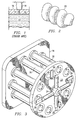
Figure 3 illustrates a perspective view of a device involving a number oftubes 30 attached to adie face 18. The exit end of eachtube 30 is attached to anextruder face 23. This arrangement then permits the attachment to theextruder face 23 of acircular cutting apparatus 24 having a number ofindividual cutting blades 26. Such all arrangement is shown with tentubes 30 connected to adie face 18. Although not shown inFigure 3 , thetube 30 andextruder face 23 configuration can be designed such that thedies 12 are allowed to vent until specific conditions are met (such as extrudate bulk density, specific mechanical energy, moisture content, screw speed, and die pressure), then thetube 30 can be rotated over thedies 12 by device of an additional rotatable plate (not shown) between thetubes 30 and thedies 12. - However, cutting the curly puff extrudate 20 at the end of the
tube 30 in amultiple tube 30 assembly is not preferable because thecutting blades 26 drag the curly puff extrudate 20 from onetube 30 to another which results in jagged and non-uniform ends of individual curly puff extrudate 20 pieces.Figure 4 is an example of a piece of curly puff extrudate 20 cut with a device similar to the one inFigure 3 . Additionally, when the curly puff extrudate 20 is produced in a multiple tube assembly, the tubes may not produce extrudate at the same rate, so a single cutter cutting multiple tubes will produce curly puff extrudate pieces of differing lengths. - This problem can be overcome by completely severing the extrudate at the die face when it is in the plastic melt state rather than the glass transition state. However, severing the extrudate at the die face disconnects the individual extrudate pieces and it is sometimes preferable to keep the extrudate connected for processing before separating the extrudate into individual extrudate pieces. Examples of processing include: conveying, seasoning, stretching, separating, or confining the extrudate in a containment vessel. Therefore, a need exists for an effective method of cutting the extrudate in the plastic melt state without completely separating the extrudate.
- Another problem with the apparatus in
figure 3 is that it does not allow for the release of steam and other hot gasses released from the expanding extrudate. The steam and other gasses promote surging and plugging within the tube. Therefore, a need also exists for an apparatus and method for venting steam and other hot gasses so they cannot enter the containment device. -
EP 022388d A1 -
GB 2,297,936 - An expandable cereal product, containing air, is supplied to the left hand end of the bore and air is supplied to the pipe through pressure regulator.
- On exiting from the die outlet air bubbles in the cereal product expand rapidly so as to thicken the wall of the cereal tube while the pressure differential between the inside and outside of the cereal tube results in inflation of the tube, thereby reducing the wall thickness of the cereal tube.
- It should be understood that while a need exist for an apparatus capable of cutting a curly puff extrudate without plugging a containment tube, the need is not limited to curly puff extrudate. A need also exists for an apparatus for cutting a sinusoidal puff extrudate as well as other types of linear and non-linear puffed extrudates.
- Consequently, a need exists for an apparatus and method of cutting the puff extrudate into smaller puff extrudate pieces that will create smooth cuts at each end of the individual pieces. A need also exists for an apparatus and method that will prevent plugging of the tube during start-up, operation, and shutdown of the extruder. A need further exists for a method of releasing steam from the expanding extrudate. Moreover, a need exists for an apparatus and method of controlling the length of the individually cut puff extrudate pieces in a configuration with multiple orifices for each die.
- The present invention provides a method of producing a plurality of extrudate pieces of puffed dough according to claim 1.
- The present invention also provides an apparatus for producing an extrudate according to claim 13.
- Preferred features are defined in the dependent claims.
- The present invention comprises a nicking blade apparatus that nicks the curly puff extrudate rather than cutting it. The nicks create a series of weak points in the curly puff extrudate. The weak points are strong enough to keep the curly puff extrudate connected during the conveying process. However, when the curly puff extrudate is further processed in an oven or fryer, the curly puff extrudate breaks at the nicks, separating the curly puff extrudate into individual pieces.
- In order to properly facilitate the nicking process while the extrudate is in the plastic melt state, the nicking should occur as close to the diehead as possible. The tube is separated from the diehead so that a blade may access the diehead orifice. The resulting separation also allows steam from the expanding extrudate to vent instead of proceeding through the tube. The release of steam allows the curly puff extrudate to flow more smoothly through the tube and helps prevent plugging and surging.
- The proposed invention also comprises a tube positioning device that positions the tube over the diehead orifice during operation, but removes the tube away from the diehead orifice start-up and shutdown. Removal of the tube from over the orifice is desired during start-up and shutdown because the extrudate tends to surge during these periods and plugs the tube. In order to facilitate nicks of different depths, a blade positioning device is also disclosed.
- The preferred embodiment of the present invention utilizes a nicking blade for every orifice. However, as some die configurations will not allow a nicking blade for every orifice, a central blade apparatus for nicking multiple orifices is also disclosed.
- The preferred embodiment of the present invention also utilizes an oven or fryer to separate the nicked curly puff extrudate. However, under certain circumstances, an oven or fryer is not preferable, so alternate separation devices are also disclosed. Alternative separation devices include a paddle wheel, a vibrating conveyer, and a tumbler.
- The above as well as additional features and advantages of the present invention will become apparent in the following written detailed description.
- The novel features believed characteristic of the invention are set forth in the appended claims. The invention itself, however, as well as a preferred mode of use, further objectives and advantages thereof, will be best understood by reference to the following detailed description of illustrative embodiments when read in conjunction with the accompanying drawings, wherein:
-
Figure 1 is a schematic cross-section of a prior art puff extrudate die; -
Figure 2 is a perspective view of a length of curly puff extrudate product; -
Figure 3 is a perspective view of a puff extrudate face cutter applied to the curly puff extrudate production apparatus as disclosed inU.S. Patent Application 09/952,574 ; -
Figure 4 is a perspective view of a piece of curly puff extrudate cut using a puff extrudate face cutter; -
Figure 5 is a side view in elevation of one embodiment of the present invention; -
Figures 6A-6C are side views in elevation of the positioning of the tube from start-up through operation for one embodiment of the present invention; -
Figure 7 is a plan view of one embodiment of the present invention incorporating a configuration utilizing a single blade for each orifice; -
Figures 8A-8C are side views of one embodiment of the present invention utilizing a single nicking blade for multiple orifices; -
Figure 9 is a perspective view of piece of curly puff extrudate cut with the present invention; and -
Figures 10A-10B are front views in elevation of the paddle wheel separator of the present invention. -
Figure 5 is an elevation view of one embodiment of the present invention. Identical reference numerals will be used to identify identical elements throughout all of the drawings, unless otherwise indicated. As with the prior art, theextrudate 16 exits anorifice 14 in thedie 12. The cross-sectional diameter of theorifice 14 is dependent on the specific dough formulation, throughput rate, and desired rod (or other shape) diameter, but is preferred in the range of 1 mm to 14 mm. (Theorifice 14 diameter is also dependent on the mean particle size of the corn meal or formula mix being extruded.) - If a
curly puff extrudate 20 is desired, atube 30 with aflapper 32 can be used. Aflapper 32 puts pressure on theextrudate 16 exiting theorifice 14 so that curls will form in theextrudate 16. Atube positioning device 34 is used to position thetube 30 in front of or away from theorifice 14. Thetube positioning device 34 is capable of moving thetube 30 in any direction relative to thedie 12. Examples of tube positioning devices are electrical servo motors, pneumatic actuators, hydraulic actuators, and mechanical screws. Atube blade 36 is also affixed to the end of thetube 30 closest to thedie 12. - A
nicking blade 40 is positioned flush with thedie face 18 and either rotates or oscillates about ashaft 44. Thenicking blade 40 and theshaft 44 are powered by amotor 42, which is connected to ablade positioning device 46. Theblade positioning device 46 is capable of moving themotor 42, theshaft 44, and thenicking blade 40 in any direction relative to thedie 12. Examples ofblade positioning devices 46 are electrical servo motors, pneumatic actuators, hydraulic actuators, and mechanical screws. In order to effectively nick theextrudate 16 exiting theorifice 14, thenicking blade 40 is positioned such that the end of thenicking blade 40 only partially covers theorifice 14 when passing in front of theorifice 14. Allowing thenicking blade 40 to completely cover theorifice 14 would completely sever theextrudate 16, which would not allow theextrudate 16 to remain connected for additional processing. It should be understood that the extent to which thenicking blade 40 covers theorifice 14 determines the depth of the nick in theextrudate 16. Deeper nicks will allow theextrudate 16 to break more easily, a property referred to here as breakability. Shallower nicks will allow theextrudate 16 to stay connected more easily, a property referred to here as connectivity. The amount of coverage over theorifice 14 is expressed as a coverage percentage that is equal to the length of thenicking blade 40 covering theorifice 14 divided by theorifice 14 cross-sectional diameter. The coverage percentage desired will depend on the type ofviscous melt 10 andorifice 14 size. Coverage percentages of eighty to ninety percent have generally been found to be an acceptable balance between breakability and connectivity for themelt 10 andorifice 14 size described herein. If desired, the rate at which thenicking blade 40 nicks theextrudate 16 can be increased such that thenicking blade 40 nicks theextrudate 16 faster than theextrudate 16 curls. When this is done and the nickedextrudate 16 is separated, smaller "C" shaped pieces of extrudate are formed. - Another factor affecting the nick size is the
nicking blade 40 tip shape. Whilepointed nicking blades 40 are capable of nicking theextrudate 16, square edged nicking blades 40 (i.e. where the edge of thenicking blade 40 contains two ninety degree angles) have proven more effective at creating uniform nicks in thecurly puff extrudate 20. - During start up, the
tube 30 is positioned away from theorifice 14 with thetube blade 36 placed firmly against thedie face 18. As the extruder starts and approaches operating parameters, it will extrudeundesirable extrudate 16. The extruder also extrudes an excess amount of hot gasses, such as steam, from theorifice 14 during start up. Steam and other hot gasses tend to cause plugging in thetube 30. Positioning thetube 30 away from theorifice 14 allows theundesired extrudate 16 to bypass thetube 30 and prevents theundesired extrudate 16, steam, and other hot gases from plugging thetube 30. Themotor 42 is generally not run during start up so that the start upextrudate 16 is not nicked. Alternatively, if themotor 42 is running, theblade positioning device 46 can position the movingnicking blade 40 such that theblade cutting radius 22 does not cover theorifice 14, and thenicking blade 40 will not nick theextrudate 16 nor interfere with the positioning of thetube 30. In this manner, themotor 42 and thenicking blade 40 can be brought up to operating speed without nicking theextrudate 16 or interfering with the positioning of thetube 30. If desired, thenicking blade 40 can be positioned by theblade positioning device 46 such that it completely cuts theextrudate 16 exiting theorifices 14. This method cuts theextrudate 16 into smaller pieces and eliminates the need for a separating device. -
Figures 6A-6C illustrate the process of starting up and operating one embodiment of the present invention. When the extruder reaches its operational parameters, thetube positioning device 34 positions thetube 30 so that thetube blade 36 is flush with the die face 18 (Seefigure 6A ). Thetube positioning device 34 then quickly slides thetube 30 across thedie face 18 until theorifice 14 is within the inside diameter of the tube 30 (Seefigure 6B ). When thetube blade 36 passes over theorifice 14, thetube blade 36 slices off theold extrudate 16 and allows theorifice 14 to extrude anew extrudate 16 into thetube 30, where theflapper 32 will contact theextrudate 16 and cause it to curl and form thecurly puff extrudate 20. - After the
tube positioning device 34 positions thetube 30 over theorifice 14, thetube positioning device 34 moves thetube 30 away from the die 12 (Seefigure 6C ). Separating thetube 30 from thedie face 18 creates agap 38. Thegap 38 allows gasses such as steam to escape from the expandingextrudate 16 and allows thenicking blade 40 to access theextrudate 16 as it exits theorifice 14. Gap distances of 4-8 millimeters have been found to be a good balance between containing the curling extrudate inside thetube 30, allowing thenicking blade 40 access to theextrudate 16, and allowing sufficient release of steam. It should be understood that thegap 38 may vary depending on the pressure and temperature of theextrudate 16, the back pressure created byflapper 32, and the thickness of thenicking blade 40. - It should also be understood that multiple embodiments of the
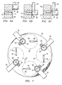
orifice 14, thenicking blade 40, and thetube 30 can be implemented on asingle die 12.Figure 7 is an illustration of a die 12 with four such embodiments. Theblade cutting radius 22 is defined by the outer reach of thenicking blade 40 and is shown only partially covering theorifice 14. The position of thenicking blade 40 shown infigure 7 is preferable to other configurations, such as one in which theshaft 44 is closer to the edge of thedie face 18, because theblade cutting radius 22 does not extend beyond the perimeter of thedie face 18. Keeping theblade cutting radius 22 within the perimeter of thedie face 18 helps prevent injury to people working in close proximity to the extruder and thedie 12. During operation of a die 12 withmultiple orifices 14, theextrudate 16 discharge rate may vary from oneorifice 14 to another. The embodiment utilizing onenicking blade 40 for everyorifice 14 is preferred because it allows an operator or automated controller to adjust thenicking blade 40 speed based on theextrudate 16 output rate and curling rate. By adjusting the speed of thenicking blade 40 to the output rate of theextrudate 16 of anindividual orifice 14, the distance between the nicks on the extrudate 16 from eachindividual orifice 14 can be precisely controlled and thus yieldcurly puff extrudate 20 pieces of uniform length. - In certain situations, an embodiment utilizing a
nicking blade 40 for everyorifice 14 may not be necessary or preferable. In these cases, acentral nicking apparatus 62, as shown infigures 8A, 8B , and8C , utilizing a central nicking apparatus positioning device (not shown), ablade positioning device 64, and at least oneblade 60 can be utilized. The central nicking apparatus positioning device can move thecentral nicking apparatus 62 in any direction relative to thedie 12. Examples of central nickingapparatus positioning devices 62 are electrical servo motors, pneumatic actuators, hydraulic actuators, and mechanical screws. Acentral nicking apparatus 62 like the one utilized infigures 8A-8C can be used to cut or nick a plurality oforifices 14.Figures 8A-8C are illustrations of the process of positioning thecentral nicking apparatus 62 into the center of thedie face 18 such that theblades 60 of thecentral nicking apparatus 62 are able to nickmultiple orifices 14. InFigure 8A , thecentral nicking apparatus 62 is positioned close to thedie face 18. A motor (not shown) powers thecentral nicking apparatus 62. As thecentral nicking device 62 begins to rotate, the centrifugal force, caused by the rotation of thecentral nicking apparatus 62, forces opens theblades 60. Theblade positioning device 64 guides theblades 60 into position such that they will be parallel with thedie face 18 when completely opened. Alternatively, theblade positioning device 64 can be actuated or otherwise controlled to force theblades 60 into position. InFigure 8B , the centrifugal force continues to expand theblades 60 and positions them adjacent to thedie face 18. The nickingapparatus 62 continues to rotate so that theblades 60 are moved into position and nick theextrudates 16 exiting the orifices 14 (Seefigure 8C ). Theblades 60 can also be extended far enough to completely sever theextrudates 16 exiting theorifices 14. - Referring back to
figure 5 , after exiting thetube 30, thecurly puff extrudate 20 is generally transported to an oven for baking or a fryer for frying. The nicks incurly puff extrudate 20 are weaker than the rest of thecurly puff extrudate 20 and, consequently, thecurly puff extrudate 20 breaks into individualcurly puff extrudate 20 pieces with little or no mechanical manipulation upon baking or frying.Figure 9 is an example of a nickedcurly puff extrudate 20 piece that has separated in a fryer. - In some applications, it may be desirable to separate the individual
curly puff extrudate 20 pieces prior to baking, frying, or some other processing. In that case, there are a variety of devices that can be used to separate the nickedcurly puff extrudate 20. One type of separation device is a paddle wheel.Figures 10A and 10B are illustrations of a paddle wheel. In the embodiment disclosed infigures 10A and 10B , thecurly puff extrudate 20 exits thetube 30 and travels along a conveyer belt, which is parallel to theshaft 70 of the paddle wheel. The view infigures 10A and 10B is that of thecurly puff extrudate 20 being conveyed out of the page towards the viewer. Each paddle wheel comprises ashaft 70 connected to a motor (not shown). A plurality ofpaddles 72 are connected to theshaft 70. When theshaft 70 rotates, thepaddles 72 come into contact the nicked curly puff extrudate 20 (Figure 10A ). By this point, thecurly puff extrudate 20 has cooled sufficiently to harden. When thepaddles 72 come into contact with thecurly puff extrudate 20, the nickedcurly puff extrudate 20 breaks at its weakest point, namely the nick. The individualcurly puff extrudate 20 pieces then fall into a capture bin underneath the paddle wheel (Figure 10B ). Aguide 74 keeps thecurly puff extrudate 20 from repositioning itself out of the reach of thepaddles 72. - It should be realized that a paddle wheel is not the only device for separating the individual
curly puff extrudate 20 pieces. A tumbler could be employed to tumble the unseparatedcurly puff extrudate 20 until thecurly puff extrudate 20 pieces break off. Thecurly puff extrudate 20 pieces could then be removed from the tumbler. Thecurly puff extrudate 20 can also be separated on a vibrating conveyer or a conveyer having steps or direction changes that facilitate product separation. Persons skilled in the art will also be aware of various other devices for separating nickedcurly puff extrudate 20. - While the present invention is disclosed in reference to
curly puff extrudate 20, it should be understood that the present invention could be employed with cylindrical, uniquely shaped, or any other type ofextrudate 16. Additionally, the present invention can be utilized any time there is an need for cutting or nicking of a quasi-solid effluent from any type of process. - It should further be understood that more than one die 12 could be routed into a
single tube 30. For example, atube 30 can receive the extrudate 16 from twonearby orifices 14. Further, dies 12 producing any number of shapes, such as a star or square cross section or more complex shapes, such as a cactus or pepper shape, can be used with the invention. - Any number of various types of extruders can be used with the invention, including twin screw and single screw extruders of any length and operating at a wide range of rotational speeds. Further, while the process has been described with regard to a corn-based product, it should be understood that the invention can be used with any puff extrudate, including products based primarily on wheat, rice, or other typical protein sources or mixes thereof. In fact, the invention could have applications in any field involving extrusion of a material that quickly goes through a glass transition stage after being extruded through a die orifice.
Claims (25)
- A method of producing a plurality of extrudate pieces wherein the extrudate (16) is a puffed dough, comprising:extruding an extrudate (16) such that said extrudate exits an extruder in a plastic melt stage;nicking the extrudate (16) while the extrudate is in the plastic melt stage with a nicking device;characterized by processing the extrudate; (16) wherein the extrudate (16) remains connected during processing, and wherein the processing comprises passing the extrudate (16) through a containment vessel and applying a resistance to the extrudate (16) to produce a non-linear extrudate (20); andseparating the extrudate (16) into pieces delineated by the area of the nicks in the extrudate using a separation device.
- The method of claim 1 wherein the nicking device is a blade (40).
- The method of claim 2 wherein the blade nicks the extrudate exiting an orifice (14) in a die (12).
- The method of claim 2 wherein the blade (40) nicks a plurality of extrudates exiting a plurality of orifices (14) in a die (12).
- The method of claim 1 wherein the nicking device accesses the extrudate (16) through a gap (38) in between a die (12) and the containment vessel.
- The method of claim 1 further comprising:positioning the containment vessel away from an orifice (14) in a die (12) such that the extrudate (16) does not pass through the containment vessel; andrepositioning the containment vessel in front of the orifice (14) such that the extrudate (16) passes through the containment vessel.
- The method of claim 1 further comprising:positioning the nicking device away from an orifice (14) in a die (12) of an extruder such that the nicking device does not nick the extrudate (16); andrepositioning the nicking device in front of the orifice (14) such that the nicking device nicks the extrudate (16).
- The method of claim 1 wherein the step of separating said extrudate (16) occurs during a baking step.
- The method of claim 1 wherein the step of separating said extrudate (16) occurs during a frying step.
- The method of claim 1 wherein the step of separating said extrudate (16) occurs during a conveying step with a paddle wheel.
- The method of claim 1 wherein the step of separating said extrudate (16) occurs during a tumbling step.
- The method of claim 1 wherein the step of separating said extrudate (16) occurs during a conveying step.
- An apparatus for producing an extrudate (16), wherein the extrudate (16) is a puffed dough, comprising:an extruder die comprising at least one orifice (14);a nicking device located in front of the die (12);wherein the nicking device is positioned to nick an extrudate (16) exiting the orifice in the die while said extrudate is in a plastic melt stage;
characterized by the apparatus further comprising: a processing device; wherein the processing device is a containment vessel located in front of the die (12) for applying a resistance to the extrudate (16) to produce a non-linear extrudate (20); and a separation device; wherein the separation device suited for separating the nicked extrudate (16) at the nicks. - The apparatus of claim 13 wherein the nicking device is a blade (40).
- The apparatus of claim 14 wherein the blade (40) nicks the extrudate (16) while the extrudate (16) is in a plastic melt stage.
- The apparatus of claim 14 wherein the blade (40) nicks the extrudate (16) from a plurality of the orifices (14).
- The apparatus of claim 13 wherein the nicking device accesses the extrudate (16) through a gap in between the die (12) and the containment vessel.
- The apparatus of claim 13 wherein the separation device is an oven.
- The apparatus of claim 13 wherein the separation device is a fryer.
- The apparatus of claim 13 wherein the separation device is a paddle wheel.
- The apparatus of claim 13 wherein the separation device is a tumbler.
- The apparatus of claim 13 wherein the separation device is a conveyer.
- The apparatus of anyone of claims 13 to 16 for producing a non-linear extrudate, wherein the extrudate (16) is a puffed dough, further comprising:a containment vessel positioning device connected to the containment vessel;a nicking device positioning device connected to the nicking device; wherein an extrudate (16) exits the orifice (14) in a plastic melt stage and passes through the containment device;and wherein the nicking device is positioned to access the extrudate (16) through a gap (38) in between the containment vessel and the die (12).
- The apparatus of claim 23 further comprising:wherein the containment vessel positioning device positions the containment vessel away from the orifice (14) such that the extrudate (16) does not pass through the containment vessel; andwherein the containment vessel positioning device repositions the containment vessel in front of the orifice (14) such that the extrudate (16) passes through the containment vessel.
- The apparatus of claim 23 further comprising:wherein the nicking device positioning device positions the nicking device away from the orifice (14) such that the nicking device does not nick the extrudate (16); andwherein the nicking device positioning device repositions the nicking device in front of the orifice (14) such that the nicking device nicks the extrudate (16).
Applications Claiming Priority (3)
| Application Number | Priority Date | Filing Date | Title |
|---|---|---|---|
| US270756 | 1981-06-05 | ||
| US10/270,756 US6797213B2 (en) | 2002-10-15 | 2002-10-15 | Method and apparatus for producing a curly puff extrudate |
| PCT/US2003/029780 WO2004035294A1 (en) | 2002-10-15 | 2003-09-18 | Improved method and apparatus for producing a curly puff extrudate |
Publications (3)
| Publication Number | Publication Date |
|---|---|
| EP1558436A1 EP1558436A1 (en) | 2005-08-03 |
| EP1558436A4 EP1558436A4 (en) | 2006-01-18 |
| EP1558436B1 true EP1558436B1 (en) | 2009-04-01 |
Family
ID=32068999
Family Applications (1)
| Application Number | Title | Priority Date | Filing Date |
|---|---|---|---|
| EP03752553A Expired - Lifetime EP1558436B1 (en) | 2002-10-15 | 2003-09-18 | Method and apparatus for producing a puffed dough extrudate |
Country Status (16)
| Country | Link |
|---|---|
| US (2) | US6797213B2 (en) |
| EP (1) | EP1558436B1 (en) |
| JP (1) | JP4324557B2 (en) |
| KR (1) | KR100715087B1 (en) |
| CN (1) | CN100522556C (en) |
| AR (1) | AR041533A1 (en) |
| AT (1) | ATE427204T1 (en) |
| AU (1) | AU2003270840B2 (en) |
| CA (1) | CA2501334C (en) |
| DE (1) | DE60326982D1 (en) |
| ES (1) | ES2325069T3 (en) |
| MX (1) | MXPA05004012A (en) |
| RU (1) | RU2297912C2 (en) |
| TW (1) | TWI228394B (en) |
| WO (1) | WO2004035294A1 (en) |
| ZA (1) | ZA200502952B (en) |
Families Citing this family (37)
| Publication number | Priority date | Publication date | Assignee | Title |
|---|---|---|---|---|
| US6722873B2 (en) * | 2001-09-10 | 2004-04-20 | Recot, Inc. | Apparatus for producing a curly puff extrudate |
| DE20301908U1 (en) * | 2003-02-07 | 2004-06-09 | Vemag Maschinenbau Gmbh | Portioning device for food |
| US8087921B2 (en) * | 2003-06-27 | 2012-01-03 | Biosphere Holdings Corporation | Extrusion mold and method of use |
| US8002534B2 (en) * | 2004-09-15 | 2011-08-23 | Lowry Stanley N | Methods and apparatuses for cutting dough utilizing a shaped opening |
| JP4318122B2 (en) * | 2005-05-24 | 2009-08-19 | トキワケミカル工業株式会社 | Synthetic resin core manufacturing method |
| US7612031B2 (en) * | 2005-12-15 | 2009-11-03 | Kimberly-Clark Worldwide, Inc. | Health-and-hygiene appliance comprising a dispersible component and a releasable component disposed adjacent or proximate to said dispersible component; and processes for making said appliance |
| US7883735B2 (en) | 2006-08-07 | 2011-02-08 | Kellogg Company | Apparatus and method for curled extrudate |
| US9247752B2 (en) * | 2006-08-07 | 2016-02-02 | Kellogg Company | Apparatus and method for curled extrudate |
| US20080248180A1 (en) * | 2007-04-03 | 2008-10-09 | Michelle Latrese Barnett | Extruded legume snack food |
| USD614831S1 (en) * | 2008-01-18 | 2010-05-04 | Barilla G. E R. Fratelli S.P.A. | Pasta |
| US20100123262A1 (en) * | 2008-11-18 | 2010-05-20 | Lewis Conrad Keller | Multi-orifice extrusion die and method for obtaining uniform flow |
| CN101991052B (en) * | 2009-08-20 | 2013-04-24 | 通用磨坊销售公司 | Method and equipment for preparing dumplings |
| USD636970S1 (en) * | 2010-06-30 | 2011-05-03 | Sargento Foods, Inc. | Cheese food product |
| USD636971S1 (en) * | 2010-08-16 | 2011-05-03 | Frito-Lay North America, Inc. | Corn-based, ready to eat snack piece |
| US9277753B2 (en) | 2010-08-20 | 2016-03-08 | Frito-Lay North America, Inc. | Synchronized cutting and injection system and method |
| MX339388B (en) * | 2011-03-14 | 2016-05-24 | Kellog Co | Apparatus for curled extruded food product. |
| USD713617S1 (en) * | 2012-11-07 | 2014-09-23 | Cj Cheiljedang Corp. | Snack food |
| USD716520S1 (en) * | 2013-03-15 | 2014-11-04 | J.R. Simplot Company | Spiral potato piece |
| USD716519S1 (en) * | 2013-03-15 | 2014-11-04 | J.R. Simplot Company | Spiral potato piece |
| USD716518S1 (en) * | 2013-03-15 | 2014-11-04 | J.R. Simplot Company | Spiral potato piece |
| USD723241S1 (en) * | 2013-03-15 | 2015-03-03 | J.R. Simplot Company | Spiral potato piece |
| USD723243S1 (en) * | 2013-03-15 | 2015-03-03 | J.R. Simplot Company | Spiral potato piece |
| USD723242S1 (en) * | 2013-03-15 | 2015-03-03 | J.R. Simplot Company | Spiral potato piece |
| USD716517S1 (en) * | 2013-03-15 | 2014-11-04 | J.R. Simplot Company | Spiral potato piece |
| USD712618S1 (en) * | 2013-05-30 | 2014-09-09 | Mccain Foods Limited | Root vegetable product |
| USD747841S1 (en) * | 2014-06-09 | 2016-01-26 | Royal Pet Incorporated | Pet treat |
| US20160218021A1 (en) * | 2015-01-27 | 2016-07-28 | Advanced Semiconductor Engineering, Inc. | Semiconductor package and method of manufacturing the same |
| US11089799B2 (en) | 2015-07-15 | 2021-08-17 | Poet Research, Inc. | Food products that contain zein, and related methods |
| BR112018013547B1 (en) * | 2016-01-18 | 2022-11-01 | Kellogg Company | APPARATUS AND METHOD FOR PRODUCING CEREAL IN THE FORM OF FLAKES WITHOUT THE USE OF A FLAKE FORMING MILL |
| US9750268B1 (en) * | 2016-04-19 | 2017-09-05 | Nationwide 5, Llc | Grain bulk densifying die apparatus and method |
| USD836283S1 (en) * | 2017-11-29 | 2018-12-25 | Eugenio Bortone | Spring coil puffed extrudate snack food |
| USD904726S1 (en) * | 2018-08-24 | 2020-12-15 | Brian Gold | Combination lollipop drinking straw |
| CN110802847B (en) * | 2019-11-04 | 2021-08-24 | 安徽杰蓝特新材料有限公司 | Processing device for PE solid-wall pipe |
| GB2598280B (en) * | 2020-06-25 | 2023-09-13 | Plant Meat Ltd | Retractable Guide |
| US11889851B2 (en) | 2021-02-01 | 2024-02-06 | Frito-Lay North America, Inc. | Method and composition of chickpea flour |
| JP7252272B2 (en) * | 2021-03-05 | 2023-04-04 | レオン自動機株式会社 | Molding method for twisted products |
| TWI845044B (en) * | 2022-12-01 | 2024-06-11 | 源創食品機械有限公司 | Puffing device for making twist roll food |
Family Cites Families (33)
| Publication number | Priority date | Publication date | Assignee | Title |
|---|---|---|---|---|
| GB882875A (en) * | 1959-09-23 | 1961-11-22 | Ici Ltd | Production of moulding compositions |
| US3215094A (en) * | 1964-07-13 | 1965-11-02 | Gen Foods Corp | Extrusion apparatus and process |
| US3444826A (en) * | 1967-03-29 | 1969-05-20 | Koninkl Vekade Fabrieken Nv | Method and apparatus for making a baked edible tubular product |
| LU64946A1 (en) * | 1971-03-26 | 1972-07-07 | ||
| US3847531A (en) * | 1973-08-29 | 1974-11-12 | K Mccomb | Die assembly for foodstuff extruder |
| IT1065137B (en) * | 1976-08-05 | 1985-02-25 | Sir Soc Italiana Resine Spa | MOLDING COMPOSITIONS INCLUDING A NOVOLACCA PHENOLIC RESIN AND PROCEDURE FOR THEIR PREPARATION |
| US4097213A (en) | 1977-02-28 | 1978-06-27 | Dorsey-Mccomb Distributors, Inc. | Mechanism for adjusting an extrusion die in cereal grain extruder apparatus |
| US4288463A (en) | 1979-01-25 | 1981-09-08 | Groff Edwin I | Method of making pretzels of selected spiral pitch |
| US4264635A (en) * | 1979-04-04 | 1981-04-28 | Wilde Stanley A | Automatic pasta perforator and method of making pasta |
| US4290989A (en) | 1979-12-10 | 1981-09-22 | Frito-Lay, Inc. | Method and apparatus for extruding a plurality of ribbons |
| US4353498A (en) * | 1981-01-05 | 1982-10-12 | Health-Ex Corporation | Multiple ply coextrusion |
| US4454804A (en) * | 1981-06-18 | 1984-06-19 | Carnation Company | Apparatus for incorporating additives in extruded foods |
| DE3515616A1 (en) * | 1985-04-30 | 1986-10-30 | Heinz Schaaf Nahrungsmittel-Extrusionstechnik, 6277 Bad Camberg | DEVICE FOR EXTRUDING FOOD |
| EP0223884A1 (en) * | 1985-10-24 | 1987-06-03 | Meiji Milk Products Company Limited | Bar-shaped ice cake product and method and apparatus for it's manufacture |
| US4803091A (en) | 1986-01-31 | 1989-02-07 | Borden, Inc. | Corn spirals and method of manufacture |
| US4698004A (en) | 1986-03-05 | 1987-10-06 | Nabisco Brands, Inc. | Nozzle for extrusion |
| US4888192A (en) | 1986-03-05 | 1989-12-19 | Nabisco Brands, Inc. | Method for extrusion of baked goods |
| DE3612211A1 (en) * | 1986-04-11 | 1987-10-15 | Basf Ag | CONTINUOUS TABLET METHOD |
| US5077074A (en) * | 1989-06-07 | 1991-12-31 | Nabisco Brands, Inc. | Preparation of cookie products involving extrusion heating and wire cutting |
| DE4115609C1 (en) * | 1991-05-14 | 1992-04-23 | Real Gmbh, 8717 Mainbernheim, De | |
| US5304055A (en) * | 1991-11-27 | 1994-04-19 | Nabisco, Inc. | Apparatus and methods for the production of three-dimensional food products |
| CN2166606Y (en) * | 1992-12-14 | 1994-06-01 | 桂恩亮 | Extruding machine for making dumpling food |
| US5637341A (en) * | 1993-11-03 | 1997-06-10 | Rivlin; Ram | Method and apparatus for producing braided baked products |
| DK0704158T3 (en) * | 1994-09-29 | 2001-09-24 | Nestle Sa | extruder |
| GB2297936A (en) * | 1995-02-15 | 1996-08-21 | Apv Corp Ltd | Extrusion and expansion of cereal products |
| US5641529A (en) | 1995-03-15 | 1997-06-24 | The Quaker Oats Company | Extrusion apparatus and method for producing three-dimensional shapes |
| DE19530270A1 (en) * | 1995-08-17 | 1997-02-20 | Meeth Ernst Josef | Process for the production of profile material for window and door production |
| ATE208254T1 (en) * | 1995-11-29 | 2001-11-15 | Nestle Sa | CUTTING DEVICE |
| EP0800772B1 (en) | 1996-04-12 | 2001-07-25 | Societe Des Produits Nestle S.A. | Process and apparatus for manufacturing extruded ice confection |
| US6086352A (en) | 1997-04-12 | 2000-07-11 | Mcfarland; Archie Rae | Apparatus for extruding products made up of composite materials |
| US6299774B1 (en) * | 2000-06-26 | 2001-10-09 | Jack L. Ainsworth | Anaerobic digester system |
| US6770233B2 (en) * | 2001-09-10 | 2004-08-03 | Frito-Lay North America, Inc. | Flapper assembly for producing a curly puff extrudate |
| US6607772B1 (en) * | 2002-02-08 | 2003-08-19 | Recot, Inc. | Method and apparatus for producing a braided puff extrudate |
-
2002
- 2002-10-15 US US10/270,756 patent/US6797213B2/en not_active Expired - Lifetime
-
2003
- 2003-09-18 JP JP2004544762A patent/JP4324557B2/en not_active Expired - Fee Related
- 2003-09-18 CA CA002501334A patent/CA2501334C/en not_active Expired - Fee Related
- 2003-09-18 DE DE60326982T patent/DE60326982D1/en not_active Expired - Fee Related
- 2003-09-18 CN CNB038243202A patent/CN100522556C/en not_active Expired - Fee Related
- 2003-09-18 AU AU2003270840A patent/AU2003270840B2/en not_active Ceased
- 2003-09-18 WO PCT/US2003/029780 patent/WO2004035294A1/en not_active Ceased
- 2003-09-18 ES ES03752553T patent/ES2325069T3/en not_active Expired - Lifetime
- 2003-09-18 AT AT03752553T patent/ATE427204T1/en not_active IP Right Cessation
- 2003-09-18 RU RU2005115445/12A patent/RU2297912C2/en not_active IP Right Cessation
- 2003-09-18 EP EP03752553A patent/EP1558436B1/en not_active Expired - Lifetime
- 2003-09-18 KR KR1020057006506A patent/KR100715087B1/en not_active Expired - Fee Related
- 2003-09-18 MX MXPA05004012A patent/MXPA05004012A/en active IP Right Grant
- 2003-10-03 TW TW092127517A patent/TWI228394B/en not_active IP Right Cessation
- 2003-10-07 AR ARP030103636A patent/AR041533A1/en active IP Right Grant
-
2004
- 2004-08-17 US US10/919,642 patent/US7293974B2/en not_active Expired - Fee Related
-
2005
- 2005-04-12 ZA ZA200502952A patent/ZA200502952B/en unknown
Also Published As
| Publication number | Publication date |
|---|---|
| CA2501334A1 (en) | 2004-04-29 |
| RU2005115445A (en) | 2005-10-10 |
| JP4324557B2 (en) | 2009-09-02 |
| US6797213B2 (en) | 2004-09-28 |
| ZA200502952B (en) | 2006-02-22 |
| US20040070103A1 (en) | 2004-04-15 |
| TW200405793A (en) | 2004-04-16 |
| TWI228394B (en) | 2005-03-01 |
| RU2297912C2 (en) | 2007-04-27 |
| AU2003270840B2 (en) | 2008-04-10 |
| MXPA05004012A (en) | 2005-06-08 |
| ATE427204T1 (en) | 2009-04-15 |
| CN100522556C (en) | 2009-08-05 |
| KR20050055019A (en) | 2005-06-10 |
| KR100715087B1 (en) | 2007-05-07 |
| ES2325069T3 (en) | 2009-08-25 |
| AR041533A1 (en) | 2005-05-18 |
| EP1558436A1 (en) | 2005-08-03 |
| EP1558436A4 (en) | 2006-01-18 |
| US20050019467A1 (en) | 2005-01-27 |
| US7293974B2 (en) | 2007-11-13 |
| DE60326982D1 (en) | 2009-05-14 |
| JP2006508822A (en) | 2006-03-16 |
| AU2003270840A1 (en) | 2004-05-04 |
| CA2501334C (en) | 2007-04-10 |
| CN1997500A (en) | 2007-07-11 |
| WO2004035294A1 (en) | 2004-04-29 |
Similar Documents
| Publication | Publication Date | Title |
|---|---|---|
| US6797213B2 (en) | Method and apparatus for producing a curly puff extrudate | |
| US20080054513A1 (en) | Method and Apparatus for Cutting a Curly Puff Extrudate | |
| AU2003207482B2 (en) | Method and apparatus for producing a braided puff extrudate | |
| US5149555A (en) | Method for forming an open textured product | |
| EP2061330B1 (en) | Production of edible wafers by extrusion | |
| CA2457795C (en) | Method and apparatus for producing a curly effect puff extrudate | |
| CA1329728C (en) | Method and apparatus for forming an open textured product | |
| Narayanan | Advances in auxiliary technologies for extrusion processing | |
| CN116686858A (en) | Fried dough twist production device | |
| HK1132884B (en) | Production of edible wafers by extrusion |
Legal Events
| Date | Code | Title | Description |
|---|---|---|---|
| PUAI | Public reference made under article 153(3) epc to a published international application that has entered the european phase |
Free format text: ORIGINAL CODE: 0009012 |
|
| 17P | Request for examination filed |
Effective date: 20050414 |
|
| AK | Designated contracting states |
Kind code of ref document: A1 Designated state(s): AT BE BG CH CY CZ DE DK EE ES FI FR GB GR HU IE IT LI LU MC NL PT RO SE SI SK TR |
|
| AX | Request for extension of the european patent |
Extension state: AL LT LV MK |
|
| A4 | Supplementary search report drawn up and despatched |
Effective date: 20051201 |
|
| RIC1 | Information provided on ipc code assigned before grant |
Ipc: B29C 47/00 19850101AFI20040504BHEP Ipc: B29C 69/02 19850101ALI20051125BHEP Ipc: B29C 69/00 19850101ALI20051125BHEP |
|
| DAX | Request for extension of the european patent (deleted) | ||
| RIN1 | Information on inventor provided before grant (corrected) |
Inventor name: ORR, DANIEL, EUGENE Inventor name: BORTONE, EUGENIO Inventor name: SUTARIA, DEVANG, JITENDRA |
|
| 17Q | First examination report despatched |
Effective date: 20060215 |
|
| GRAP | Despatch of communication of intention to grant a patent |
Free format text: ORIGINAL CODE: EPIDOSNIGR1 |
|
| RTI1 | Title (correction) |
Free format text: METHOD AND APPARATUS FOR PRODUCING A PUFFED DOUGH EXTRUDATE |
|
| GRAS | Grant fee paid |
Free format text: ORIGINAL CODE: EPIDOSNIGR3 |
|
| GRAA | (expected) grant |
Free format text: ORIGINAL CODE: 0009210 |
|
| AK | Designated contracting states |
Kind code of ref document: B1 Designated state(s): AT BE BG CH CY CZ DE DK EE ES FI FR GB GR HU IE IT LI LU MC NL PT RO SE SI SK TR |
|
| REG | Reference to a national code |
Ref country code: GB Ref legal event code: FG4D |
|
| REG | Reference to a national code |
Ref country code: CH Ref legal event code: EP |
|
| REG | Reference to a national code |
Ref country code: IE Ref legal event code: FG4D |
|
| REF | Corresponds to: |
Ref document number: 60326982 Country of ref document: DE Date of ref document: 20090514 Kind code of ref document: P |
|
| REG | Reference to a national code |
Ref country code: RO Ref legal event code: EPE |
|
| REG | Reference to a national code |
Ref country code: GR Ref legal event code: EP Ref document number: 20090401540 Country of ref document: GR |
|
| PG25 | Lapsed in a contracting state [announced via postgrant information from national office to epo] |
Ref country code: SI Free format text: LAPSE BECAUSE OF FAILURE TO SUBMIT A TRANSLATION OF THE DESCRIPTION OR TO PAY THE FEE WITHIN THE PRESCRIBED TIME-LIMIT Effective date: 20090401 |
|
| REG | Reference to a national code |
Ref country code: ES Ref legal event code: FG2A Ref document number: 2325069 Country of ref document: ES Kind code of ref document: T3 |
|
| NLV1 | Nl: lapsed or annulled due to failure to fulfill the requirements of art. 29p and 29m of the patents act | ||
| PG25 | Lapsed in a contracting state [announced via postgrant information from national office to epo] |
Ref country code: FI Free format text: LAPSE BECAUSE OF FAILURE TO SUBMIT A TRANSLATION OF THE DESCRIPTION OR TO PAY THE FEE WITHIN THE PRESCRIBED TIME-LIMIT Effective date: 20090401 Ref country code: PT Free format text: LAPSE BECAUSE OF FAILURE TO SUBMIT A TRANSLATION OF THE DESCRIPTION OR TO PAY THE FEE WITHIN THE PRESCRIBED TIME-LIMIT Effective date: 20090902 Ref country code: AT Free format text: LAPSE BECAUSE OF FAILURE TO SUBMIT A TRANSLATION OF THE DESCRIPTION OR TO PAY THE FEE WITHIN THE PRESCRIBED TIME-LIMIT Effective date: 20090401 Ref country code: EE Free format text: LAPSE BECAUSE OF FAILURE TO SUBMIT A TRANSLATION OF THE DESCRIPTION OR TO PAY THE FEE WITHIN THE PRESCRIBED TIME-LIMIT Effective date: 20090401 |
|
| PG25 | Lapsed in a contracting state [announced via postgrant information from national office to epo] |
Ref country code: SE Free format text: LAPSE BECAUSE OF FAILURE TO SUBMIT A TRANSLATION OF THE DESCRIPTION OR TO PAY THE FEE WITHIN THE PRESCRIBED TIME-LIMIT Effective date: 20090701 Ref country code: NL Free format text: LAPSE BECAUSE OF FAILURE TO SUBMIT A TRANSLATION OF THE DESCRIPTION OR TO PAY THE FEE WITHIN THE PRESCRIBED TIME-LIMIT Effective date: 20090401 |
|
| PG25 | Lapsed in a contracting state [announced via postgrant information from national office to epo] |
Ref country code: DK Free format text: LAPSE BECAUSE OF FAILURE TO SUBMIT A TRANSLATION OF THE DESCRIPTION OR TO PAY THE FEE WITHIN THE PRESCRIBED TIME-LIMIT Effective date: 20090401 Ref country code: CZ Free format text: LAPSE BECAUSE OF FAILURE TO SUBMIT A TRANSLATION OF THE DESCRIPTION OR TO PAY THE FEE WITHIN THE PRESCRIBED TIME-LIMIT Effective date: 20090401 |
|
| PLBE | No opposition filed within time limit |
Free format text: ORIGINAL CODE: 0009261 |
|
| STAA | Information on the status of an ep patent application or granted ep patent |
Free format text: STATUS: NO OPPOSITION FILED WITHIN TIME LIMIT |
|
| PG25 | Lapsed in a contracting state [announced via postgrant information from national office to epo] |
Ref country code: BE Free format text: LAPSE BECAUSE OF FAILURE TO SUBMIT A TRANSLATION OF THE DESCRIPTION OR TO PAY THE FEE WITHIN THE PRESCRIBED TIME-LIMIT Effective date: 20090401 Ref country code: SK Free format text: LAPSE BECAUSE OF FAILURE TO SUBMIT A TRANSLATION OF THE DESCRIPTION OR TO PAY THE FEE WITHIN THE PRESCRIBED TIME-LIMIT Effective date: 20090401 |
|
| 26N | No opposition filed |
Effective date: 20100105 |
|
| PG25 | Lapsed in a contracting state [announced via postgrant information from national office to epo] |
Ref country code: BG Free format text: LAPSE BECAUSE OF FAILURE TO SUBMIT A TRANSLATION OF THE DESCRIPTION OR TO PAY THE FEE WITHIN THE PRESCRIBED TIME-LIMIT Effective date: 20090701 |
|
| PG25 | Lapsed in a contracting state [announced via postgrant information from national office to epo] |
Ref country code: MC Free format text: LAPSE BECAUSE OF NON-PAYMENT OF DUE FEES Effective date: 20090930 |
|
| REG | Reference to a national code |
Ref country code: CH Ref legal event code: PL |
|
| REG | Reference to a national code |
Ref country code: FR Ref legal event code: ST Effective date: 20100531 |
|
| PG25 | Lapsed in a contracting state [announced via postgrant information from national office to epo] |
Ref country code: IE Free format text: LAPSE BECAUSE OF NON-PAYMENT OF DUE FEES Effective date: 20090918 Ref country code: DE Free format text: LAPSE BECAUSE OF NON-PAYMENT OF DUE FEES Effective date: 20100401 Ref country code: FR Free format text: LAPSE BECAUSE OF NON-PAYMENT OF DUE FEES Effective date: 20090930 |
|
| PG25 | Lapsed in a contracting state [announced via postgrant information from national office to epo] |
Ref country code: LI Free format text: LAPSE BECAUSE OF NON-PAYMENT OF DUE FEES Effective date: 20090930 Ref country code: CH Free format text: LAPSE BECAUSE OF NON-PAYMENT OF DUE FEES Effective date: 20090930 |
|
| PGFP | Annual fee paid to national office [announced via postgrant information from national office to epo] |
Ref country code: RO Payment date: 20100913 Year of fee payment: 8 |
|
| PGFP | Annual fee paid to national office [announced via postgrant information from national office to epo] |
Ref country code: GR Payment date: 20100929 Year of fee payment: 8 |
|
| PG25 | Lapsed in a contracting state [announced via postgrant information from national office to epo] |
Ref country code: IT Free format text: LAPSE BECAUSE OF FAILURE TO SUBMIT A TRANSLATION OF THE DESCRIPTION OR TO PAY THE FEE WITHIN THE PRESCRIBED TIME-LIMIT Effective date: 20090401 |
|
| PG25 | Lapsed in a contracting state [announced via postgrant information from national office to epo] |
Ref country code: LU Free format text: LAPSE BECAUSE OF NON-PAYMENT OF DUE FEES Effective date: 20090918 |
|
| PG25 | Lapsed in a contracting state [announced via postgrant information from national office to epo] |
Ref country code: HU Free format text: LAPSE BECAUSE OF FAILURE TO SUBMIT A TRANSLATION OF THE DESCRIPTION OR TO PAY THE FEE WITHIN THE PRESCRIBED TIME-LIMIT Effective date: 20091002 |
|
| PG25 | Lapsed in a contracting state [announced via postgrant information from national office to epo] |
Ref country code: CY Free format text: LAPSE BECAUSE OF FAILURE TO SUBMIT A TRANSLATION OF THE DESCRIPTION OR TO PAY THE FEE WITHIN THE PRESCRIBED TIME-LIMIT Effective date: 20090401 |
|
| REG | Reference to a national code |
Ref country code: GR Ref legal event code: ML Ref document number: 20090401540 Country of ref document: GR Effective date: 20120403 |
|
| PG25 | Lapsed in a contracting state [announced via postgrant information from national office to epo] |
Ref country code: RO Free format text: LAPSE BECAUSE OF NON-PAYMENT OF DUE FEES Effective date: 20110918 Ref country code: GR Free format text: LAPSE BECAUSE OF NON-PAYMENT OF DUE FEES Effective date: 20120403 |
|
| PGFP | Annual fee paid to national office [announced via postgrant information from national office to epo] |
Ref country code: TR Payment date: 20120910 Year of fee payment: 10 |
|
| PGFP | Annual fee paid to national office [announced via postgrant information from national office to epo] |
Ref country code: ES Payment date: 20120926 Year of fee payment: 10 |
|
| REG | Reference to a national code |
Ref country code: ES Ref legal event code: FD2A Effective date: 20141107 |
|
| PG25 | Lapsed in a contracting state [announced via postgrant information from national office to epo] |
Ref country code: ES Free format text: LAPSE BECAUSE OF NON-PAYMENT OF DUE FEES Effective date: 20130919 |
|
| PG25 | Lapsed in a contracting state [announced via postgrant information from national office to epo] |
Ref country code: TR Free format text: LAPSE BECAUSE OF NON-PAYMENT OF DUE FEES Effective date: 20130918 |
|
| PGFP | Annual fee paid to national office [announced via postgrant information from national office to epo] |
Ref country code: GB Payment date: 20150928 Year of fee payment: 13 |
|
| GBPC | Gb: european patent ceased through non-payment of renewal fee |
Effective date: 20160918 |
|
| PG25 | Lapsed in a contracting state [announced via postgrant information from national office to epo] |
Ref country code: GB Free format text: LAPSE BECAUSE OF NON-PAYMENT OF DUE FEES Effective date: 20160918 |