EP1557833B1 - Recording tape cartridge - Google Patents
Recording tape cartridge Download PDFInfo
- Publication number
- EP1557833B1 EP1557833B1 EP05001353A EP05001353A EP1557833B1 EP 1557833 B1 EP1557833 B1 EP 1557833B1 EP 05001353 A EP05001353 A EP 05001353A EP 05001353 A EP05001353 A EP 05001353A EP 1557833 B1 EP1557833 B1 EP 1557833B1
- Authority
- EP
- European Patent Office
- Prior art keywords
- door
- recording tape
- opening
- bent portion
- case
- Prior art date
- Legal status (The legal status is an assumption and is not a legal conclusion. Google has not performed a legal analysis and makes no representation as to the accuracy of the status listed.)
- Expired - Fee Related
Links
- 230000002093 peripheral effect Effects 0.000 description 8
- 229920005672 polyolefin resin Polymers 0.000 description 4
- 229920005989 resin Polymers 0.000 description 4
- 239000011347 resin Substances 0.000 description 4
- 238000004804 winding Methods 0.000 description 4
- 238000013459 approach Methods 0.000 description 2
- 239000000463 material Substances 0.000 description 2
- 206010067482 No adverse event Diseases 0.000 description 1
- 230000007547 defect Effects 0.000 description 1
- 230000005489 elastic deformation Effects 0.000 description 1
- 239000002184 metal Substances 0.000 description 1
- 230000001105 regulatory effect Effects 0.000 description 1
- 238000000926 separation method Methods 0.000 description 1
- 238000003466 welding Methods 0.000 description 1
Images


Classifications
-
- G—PHYSICS
- G11—INFORMATION STORAGE
- G11B—INFORMATION STORAGE BASED ON RELATIVE MOVEMENT BETWEEN RECORD CARRIER AND TRANSDUCER
- G11B23/00—Record carriers not specific to the method of recording or reproducing; Accessories, e.g. containers, specially adapted for co-operation with the recording or reproducing apparatus ; Intermediate mediums; Apparatus or processes specially adapted for their manufacture
- G11B23/02—Containers; Storing means both adapted to cooperate with the recording or reproducing means
- G11B23/04—Magazines; Cassettes for webs or filaments
- G11B23/08—Magazines; Cassettes for webs or filaments for housing webs or filaments having two distinct ends
- G11B23/107—Magazines; Cassettes for webs or filaments for housing webs or filaments having two distinct ends using one reel or core, one end of the record carrier coming out of the magazine or cassette
-
- G—PHYSICS
- G11—INFORMATION STORAGE
- G11B—INFORMATION STORAGE BASED ON RELATIVE MOVEMENT BETWEEN RECORD CARRIER AND TRANSDUCER
- G11B23/00—Record carriers not specific to the method of recording or reproducing; Accessories, e.g. containers, specially adapted for co-operation with the recording or reproducing apparatus ; Intermediate mediums; Apparatus or processes specially adapted for their manufacture
- G11B23/02—Containers; Storing means both adapted to cooperate with the recording or reproducing means
- G11B23/04—Magazines; Cassettes for webs or filaments
- G11B23/041—Details
- G11B23/045—Covers
Landscapes
- Packaging Of Annular Or Rod-Shaped Articles, Wearing Apparel, Cassettes, Or The Like (AREA)
Description
- The present invention relates to a recording tape cartridge in which a single reel is accommodated within a case, and a recording tape, such as a magnetic tape or the like, which is mainly used as a recording medium for a computer or the like, is wound around the reel.
- Conventionally, recording tape cartridges have been known in which a recording tape, such as a magnetic tape or the like, which is used as a data recording medium for a computer or the like, is wound around a single reel, and the reel is rotatably accommodated within a case. The case for such a recording tape cartridge is formed in the shape of a substantially rectangular box by an upper case and a lower case, respectively formed in a substantial tray shape, being joined together in a state in which peripheral walls thereof abut one another.
- In such a recording tape cartridge, a leader member such as a leader tape, a leader pin, a leader block or the like is attached to a distal end portion of the recording tape. A pull-out member (not shown) provided at a drive pulls out the leader member, and the recording tape attached to the leader member is pulled out of the case (see for example
US-A-2003 071 159 which forms the basis for the preamble of claim 1). - The pull-out member of the drive is often provided at a side portion of an opening for loading the recording tape cartridge. Accordingly, in the recording tape cartridge, an opening for pulling out the leader member of the recording tape is often provided at a corner portion of the case. Even if the opening is not provided at the corner portion, the corner portion sometimes has components which are important for the function of the recording tape cartridge, including a hinge of a door for the opening. (For example, see Japanese Patent Application Laid-Open (JP-A) No.
2000-11591 - The corner portion is most likely to receive concentrated stress when an impact is applied to the recording tape cartridge due to a fall or the like thereof. Such concentrated stress causes the corner portion to be locally deformed permanently (i.e., the corner portion becomes crushed, bent, broken or the like). Therefore, problems arise in that the recording tape cartridge cannot be loaded into the drive, the recording tape cannot be pulled out, the door for the opening cannot be opened or closed, and the like.
- Further, even if no permanent deformation is caused, deformation such as a temporary deflection, namely, elastic deformation, may be caused, resulting in separation of the peripheral wall of the upper case from the peripheral wall of the lower case. When such deflection deformation is caused, the leader member such as a leader tape may be dislodged from a portion in the case at which the leader member is held, or may be caught between the peripheral wall of the upper case and the peripheral wall of the lower case. Further, if the door is opened, the leader member may be thrown out of the case.
- In view of the aforementioned, the present invention provides a recording tape cartridge which has excellent impact resistance and in which trouble such as deformation is unlikely to occur even when an impact is applied to the recording tape cartridge due to a fall or the like thereof.
- An aspect of the present invention is a recording tape cartridge including: a case which accommodates a single reel, around which a recording tape is wound, such that the reel is rotatable; an opening formed at a corner portion extending between a front wall and a side wall of the case, the opening being for pulling-out of a leader member which is attached to a distal end portion of the recording tape; and a door which has a bent portion and which is integrally formed in a substantial L-shape in plan view, rotates around a shaft provided at the front wall side, and opens and closes the opening, wherein the plate thickness of the bent portion in a direction in which the door rotates is larger than that of the door, and a stepped portion is formed at the further end side from the bent portion of the door, wherein also the case includes a first abutting portion which abuts the door when the door closes the opening, and second abutting portions which abut the end surface of the bent portion at a door distal-end side thereof, and an inner surface of the bent portion, only while the door which has closed the opening is deflected in a direction of closing the opening.
- In this case, since the plate thickness of the bent portion in the rotation direction of the door (in the curvature radial direction), which is formed in a substantial L-shape in plan view, is larger than that of the door, even when an impact is applied to the corner portion of the case (the bent portion of the door) due to a fall or the like of the cartridge, permanent deformation or temporary deflection deformation of these portions of the case can be prevented. Further, when the door receives an impact due to a fall of the cartridge and is deflected in the direction of closing the opening, the end surface of the bent portion at a door distal-end side thereof and the inner surface of the bent portion abut the second abutting portions. Since the second abutting portions are formed separately from the first abutting portion, the impact can be received in a preferable manner. Thus, damage (such as permanent deformation) to the door can be prevented.
- The bent portion of the door may include a receiving portion which is provided at an inner surface thereof to receive a distal end portion of the leader member. Further, a predetermined clearance may be formed between the distal end portion of the leader member and the inner surface of the bent portion.
- The clearance may be formed so as to be larger than play of the door with respect to the case in the direction in which the door rotates.
- The receiving portion may have a guide portion, which is a tapered surface formed such that the inner surface of the bent portion becomes thicker toward a central portion of the bent portion in plan view. The guide portion may deflect the distal end portion of the leader member toward the central portion of the bent portion.
- A predetermined clearance may be formed between the second abutting portions and the portions of the door which abut the second abutting portions.
- Moreover, in the recording tape cartridge, a portion of the door which abuts the first abutting portion may be a distal-end-side end surface of a stepped portion of the door. The distal-end-side end surface of the stepped portion and a distal-end-side end surface of the bent portion may be inclined such that imaginary extensions thereof intersect each other at an inner side of the door in plan view.
- In this case, the distal-end-side end surface of the stepped portion which abuts the first abutting portion and the distal-end-side end surface of the bent portion which abuts the second abutting portion are inclined such that imaginary extensions thereof intersect each other at an inner side of the door in plan view. That is, the first abutting portion and the second abutting portion are also inclined such that imaginary extensions thereof intersect each other at an inner side of the door in plan view.
- Therefore, when the door receives an impact due to a fall or the like of the cartridge, the impact can be received first by the second abutting portions in a preferable manner. Then, the first abutting portion can deflect the distal end portion of the door such that the distal end portion escapes toward the outside. Thus, damage to the door or permanent deformation thereof can further be prevented.
- As described above, the present invention can provide a recording tape cartridge which has excellent impact resistance and in which trouble such as deformation is unlikely to occur even when an impact is applied to the recording tape cartridge due to a fall or the like thereof.
-
-
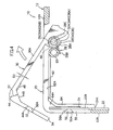
Fig. 1 is a schematic perspective view of a recording tape cartridge of an embodiment of the present invention. -
Fig. 2 is a schematic perspective view of the vicinity of an opening of the recording tape cartridge when the opening is closed. -
Fig. 3 is a schematic perspective view of the vicinity of the opening of the recording tape cartridge when the opening is opened. -
Fig. 4 is a schematic plan view of the vicinity of the opening of the recording tape cartridge when the opening is opened. -
Fig. 5 is a schematic plan view of the vicinity of the opening of the recording tape cartridge when the opening is closed. - Hereinafter, an embodiment of the present invention will be described in detail on the basis of the drawings. For convenience of explanation, the direction in which the recording tape cartridge is loaded into a drive (the direction of arrow A) is called the front direction", and the other directions, namely, rear, left (the direction of arrow B), right, top, and bottom will be specified and expressed on the basis of this front direction.
- As shown in
Fig. 1 , arecording tape cartridge 10 has acase 12, which is formed in the shape of a substantially rectangular box. Thecase 12 is formed by anupper case 14 and alower case 16, respectively formed from a resin material such as PC, being joined together by ultrasonic welding, screwing, or the like, in a state in whichperipheral walls - As shown in
Figs. 2 and3 , asingle reel 18, around which is wound a recording tape T such as a magnetic tape serving as an information recording medium, is rotatably accommodated in the interior of thecase 12. An annular reel gear (not shown) is provided on an under surface of thereel 18. The reel gear is exposed to the exterior through a gear opening (not shown) formed in thelower case 16. - An
opening 20 is formed at the front,left corner portion 12C of therecording tape cartridge 10. Thisopening 20 is provided for the pulling-out, to the exterior, of the recording tape T which is wound around thereel 18. The opening 20 is formed continuously from afront wall 12A and aleft wall 12B which are adjacent to thecorner portion 12C. Aleader tape 22, which is attached to the distal end portion of the recording tape T and is disposed along theleft wall 12B, is pulled out from the opening 20. - Note that the corner portion of the present invention refers to an edge formed at a portion where the
peripheral walls rectangular case 12 intersect at a substantially right angle or an obtuse angle in plan view. Thus, thecorner portion 12C in this case refers to an edge formed at a portion where thefront wall 12A and theleft wall 12B of the substantiallyrectangular case 12 intersect at a substantially right angle in plan view. The opening 20 may also be formed in the vicinity of a front,right corner portion 12D. - The
leader tape 22 is a pulled-out member which engages with a pull-out member (not shown) of the drive so that the recording tape T is pulled out. Anaperture 22A is formed near a distal end portion of theleader tape 22 with which the pull-out member engages. Juttedportions 22B are provided at upper and lower sides of theleader tape 22 at portions further toward the rear than a front end portion of theaperture 22A (i.e., in the vicinity of the distal end portion of the leader tape 22). The juttedportions 22B jut upward and downward from theleader tape 22. - The
leader tape 22 is held within thecase 12 by thejutted portions 22B being accommodated (inserted) in concave receivingportions 24 formed at inner surfaces of theupper case 14 and thelower case 16. Namely, as shown inFigs. 4 and5 , the concavereceiving portions 24 are formed along theleft wall 12B so as to be open toward theopening 20 at the front and closed by arear wall 24A at the rear. Therefore, theleader tape 22 is disposed along theleft wall 12B while the positions of the juttedportions 22B arc regulated by therear wall 24A. - As shown in the drawings, when the
recording tape cartridge 10 is not being used, theopening 20 is closed by adoor 30. The door is formed so as to be bent in a substantial L-shape in plan view and is substantially the same as theopening 20 in shape and size. Thedoor 30 is preferably formed by an olefin resin such as POM, but a resin material such as PC or a metal such as SUS may also be used. - A
shaft 26 which is the rotating axis of thedoor 30 is provided at thefront wall 12A side of theupper case 14 and thelower case 16. Theshaft 26 is formed as acylindrical boss 26A at theupper case 14 side and acylindrical boss 26B at thelower case 16 side thereof. An end (upper end) portion of theboss 26B at thelower case 16 side is placed within theboss 26A at theupper case 14 side to form theshaft 26. Thus, theboss 26B is slightly smaller in diameter than theboss 26A. - Plate-like rotating and sliding
portions portions door 30. The rotating and slidingportions holes shaft 26 is loosely fitted (seeFigs. 4 and5 ). Thedoor 30 is rotatably supported by theshaft 26 inserted in the throughholes - Annular projecting
portions 38 are provided around the throughholes portion 32 of the upper end portion and on the under surface of the rotating and slidingportion 34 of the lower end portion, respectively. The annular projectingportions 38 are brought into contact with theupper case 14 and thelower case 16 so that a clearance W of about 0.3 to 0.5 mm is formed between thetop end surface 30A of thedoor 30 and theupper case 14, and between thebottom end surface 30B of thedoor 30 and the lower case 16 (seeFig. 2 ). -
Elevated portions 40 are provided at an inner surface of thedoor 30 between the rotating and slidingportions shaft 26. - A winding
portion 28A of atorsion spring 28 is fitted onto theshaft 26. Thetorsion spring 28 constantly urges thedoor 30 in a direction in which thedoor 30 closes theopening 20. Namely, the windingportion 28A of thetorsion spring 28 is fitted onto theboss 26B, which is smaller in diameter than theboss 26A, while thetorsion spring 28 is held between of the rotating and slidingportion 34 at the lower end portion and therotation sliding portion 36 at the middle portion. Anend portion 28B of thetorsion spring 28 is anchored on a screw boss provided at thelower case 16 which forms thecase 12. Theother end portion 28C of thetorsion spring 28 is anchored on an edge portion of the right side of theelevated portion 40 between the rotating and slidingportions - As shown in
Fig. 5 , a pouch-like receiving portion 46 is provided at an inner surface of aportion 44, of thedoor 30, which is bent. (Thisportion 44 is thecorner portion 12C of thecase 12 and hereinafter referred to as the "bent portion 44"). When theopening 20 is closed, the distal end portion (i.e., a portion further forward than theaperture 22A) of theleader tape 22 enters the receivingportion 46. The receivingportion 46 has a guide portion 46A. As seen in plan view inFig. 5 , the left side inner surface of the guide portion 46A is formed as a thick tapered surface inclined slightly rightward at an angle θ. An inner surface of the receivingportion 46 which is the deepest (hereinafter referred to as the "deepest surface 46B") is formed as an arc surface forming an arc in plan view. - Thus, when the
opening 20 is closed, the left side surface of theleader tape 22 abuts the guide portion 46A, and the distal end portion of theleader tape 22 is slightly deflected so as to be away from theleft wall 12B. By providing such a guide portion 46A, the receivingportion 46 can be made relatively shallow. - Namely, as compared with a structure in which the left inner surface of the receiving portion is formed as a surface parallel to the
left wall 12B, i.e., a surface perpendicular to thefront wall 12A, the receivingportion 46 can be made shallow. As a result, a plate thickness D3 of the deepest surface 46B, which is the thinnest because of the receiving portion 46 (i.e., a thinnest plate thickness D3 of the door 30) may be 0.6 mm or more. In this case, the plate thickness D3 may be 0.6 to 0.9 mm, preferably 0.6 to 1.5 mm, and more preferably 0.6 to 2.0 mm. - The distal end surface 22C of the
leader tape 22 is structured so as not to be in contact with the deepest surface 46B of the receivingportion 46 when theopening 20 is closed. Namely, as shown inFig. 5 , a predetermined clearance C3 is constantly provided between the distal end surface 22C of theleader tape 22 and the deepest surface 46B of the receivingportion 46. The clearance C3 is 0.5 mm or more. Even if thedoor 30 receives an impact due to a fall or the like of the cartridge, the deepest surface 46B never interferes with (i.e., contacts) the distal end surface 22C of theleader tape 22. - Because the
door 30 closes theopening 20 with play of about 0.2 mm in a direction in which thedoor 30 rotates, when thedoor 30 receives an impact due to a fall or the like of the cartridge, thedoor 30 may rotate about 0.2 nun further in a direction in which thedoor 30 closes theopening 20. Thus, the clearance C3 between the distal end surface 22C of theleader tape 22 and the deepest surface 46B of thedoor 30 is formed to be 0.5 mm or more so that the deepest surface 46B of thedoor 30 does not interfere with or contact the distal end surface 22C of theleader tape 22 even in such a case. - At the inner surfaces of the upper and
lower cases opening 20, arib 62 of predetermined height is provided parallel to thefront wall 12A and extending from a front end portion of arib 64, which will be described later, and thescrew boss 60. Further, as shown inFig. 3 , aprojection 48 of predetermined height is provided at a top end portion and a bottom end portion of the inner surface of thedoor 30 at a portion further to the right (i.e., to thefront wall 12A side) than thebent portion 44. Thus, when thedoor 30 closes theopening 20, theprojection 48 provided at the inner surface of thedoor 30 abuts anouter surface 62A of therib 62. Theouter surface 62A of therib 62 corresponds to a first abutting portion in the present invention. - A
distal end portion 54 of thedoor 30 at theleft wall 12B side thereof is formed in the shape of a trapezoid in side view, and the width in the top and bottom direction thereof is formed smaller than that of thefront wall 12A side of thedoor 30. A steppedportion 52 is formed at the top and bottom end surfaces of thedoor 30 between thedistal end portion 54 and thebent portion 44, such that the width between the top and bottom steppedportions 52 is smaller than that of thebent portion 44 and wider than that of thedistal end portion 54. Thus, theleft wall 12B in which theopening 20 is formed also includes a steppedportion 56 of shape matching with the shape of the steppedportion 52. - As shown in
Figs. 4 and5 , anend surface 44A of thebent portion 44 at the distal-end-side thereof and anend surface 52A of the steppedportion 52 at the distal-end-side thereof are inclined such that imaginary extensions thereof intersect each other at an inner side of the door in plan view. Accordingly, corresponding end surfaces 56A, 58A are formed at steppedportions case 12 as well so as to be inclined such that imaginary extensions thereof intersect each other at an inner side of theleft wall 12B in plan view. Theend surface 56A of the steppedportion 56 corresponds to the first abutting portion, and theend surface 58A of the steppedportion 58 corresponds to the second abutting portion of the present invention. - In particular, when the
door 30 closes theopening 20, theend surface 52A of the steppedportion 52 abuts theend surface 56A of the steppedportion 56, but theend surface 44A of thebent portion 44 does not abut theend surface 58A of the steppedportion 58. That is, when thedoor 30 closes theopening 20, there is no clearance between theend surface 52A of the steppedportion 52 and theend surface 56A of the steppedportion 56, but a predetermined clearance C1 is ensured between theend surface 44A of thebent portion 44 and theend surface 58A of the steppedportion 58, as shown inFig. 5 . - An
inner surface 44B of the top and bottom end surfaces of thebent portion 44 is formed as an inclined surface in plan view, which is inclined at a predetermined angle with respect to an inner surface of thefront wall 12A and with respect to an inner surface of theleft wall 12B of thedoor 30. The plate thickness D1 of thedoor 30 in the direction in which thedoor 30 rotates is larger than a plate thickness D2 of thedoor 30 at thefront wall 12A side thereof (SeeFig. 4 ). In this way, by forming the top and bottom end surfaces of thebent portion 44 thick, thebent portion 44, which is made thinnest because of the receivingportion 46, can be reinforced. - When the
opening 20 is closed, theinner surface 44B of the top and bottom end surfaces of thebent portion 44 faces theouter surface 64A of therib 64 with a predetermined clearance C2 therebetween. Theouter surface 64A has a predetermined height and is provided at the right side of the receiving portion 24 (SeeFig. 5 ). Namely, a distal end portion of therib 64 is bent rightward at a predetermined angle so as to correspond to theinner surface 44B of thebent portion 44. Theouter surface 64A of the distal end portion of therib 64 which is bent at a predetermined angle corresponds to the second abutting portion of the present invention. Thus, when thedoor 30 closes theopening 20, theinner surface 44B of thebent portion 44 never abuts theouter surface 64A of therib 64. - The second abutting portions (the
end surface 58A and theouter surface 64A) respectively abut theend surface 44A and theinner surface 44B of thebent portion 44 of the door 30 (i.e., the clearances C1 and C2 become zero) only when thecase 12 receives an impact, due to a fall or the like of the cartridge, in the vicinity of thecorner portion 12C of the case formed by the upper andlower cases 14 and 16 (including thedoor 30 which has closed the opening 20) and thedoor 30 is deflected in the direction of closing theopening 20. The second abutting portions receive the impact force applied thereto due to a fall or the like of the cartridge. - Next, operation of the
recording tape cartridge 10 will be described. When therecording tape cartridge 10 is not being used (i.e., when therecording tape cartridge 10 is not loaded in a drive), theopening 20 is closed by thedoor 30. At this time, thedoor 30 abuts the first abutting portion. Namely, theprojections 48 of thedoor 30 abut theouter surface 62A of therib 62, and theend surface 52A of the steppedportion 52 abuts theend surface 56A of the steppedportion 56 of thecase 12. - Further, at this time, the
leader tape 22 is held within thecase 12 along theleft wall 12B with the juttedportions 22B being accommodated (inserted) in theconcave receiving portions 24. Further, the distal end portion of the leader tape 22 (the portion further toward the end than theaperture 22A) is slightly deflected by the guide portion 46A so as to be spaced away from theleft wall 12B. - Therefore, in plan view in
Fig. 5 , the guide portion 46A is formed to be thicker in the direction in which the distal end portion of theleader tape 22 is spaced away from theleft wall 12B. Namely, the left side of the inner surface of the receivingportion 46 is formed as a tapered surface inclined slightly rightward at the angle θ. Thus, the receivingportion 46 is made relatively shallow. As a result, the plate thickness D3 of the receivingportion 46 at the deepest surface 46B (i.e., the thinnest portion of the door 30) may be 0.6 mm or more. In this case, the thickness D3 may be 0.6 to 0.9 mm, preferably 0.6 to 1.5 mm, and more preferably 0.6 to 2.0 mm. Consequently, the strength of thedoor 30 is sufficiently ensured. - The predetermined clearance C3 is provided between the distal end surface 22C of the
leader tape 22 deflected by the guide portion 46A, and the deepest surface 46B of the receivingportion 46. Specifically, the clearance C3 is 0.5 mm or more. Even if thedoor 30 receives an impact due to a fall or the like of the cartridge, the distal end surface 22C of theleader tape 22 never interferes with (i.e., contacts) the deepest surface 46B of thedoor 30. - Because the play of the door 30 (in the direction in which the door rotates) with respect to the
case 12 is about 0.2 mm, even if thedoor 30 rotates further toward the direction of closing theopening 20 due to an impact, the deepest surface 46B comes closer to the distal end surface 22C of theleader tape 22 by a distance of only about 0.2 mm. Thus, the distal end surface 22C of theleader tape 22 never interferes with (or contacts) the deepest surface 46B. As a result, defects such as theleader tape 22 becoming caught between thedoor 30 and theconcave receiving portions 24 and being deformed are not caused. - When the
case 12 receives an impact, due to a fall or the like of the cartridge, in the vicinity of thecorner portion 12C of thecase 12, in particular, at thedoor 30 provided to extend over thecorner portion 12C and close theopening 20, thedoor 30 is slightly deflected and abuts the second abutting portions. Namely, theend surface 44A of thebent portion 44 of thedoor 30 abuts theend surface 58A of the steppedportion 58, and theinner surface 44B of the top and bottom surfaces of thebent portion 44 abuts theouter surface 64A of therib 64. - As described above, since the strength of the
bent portion 44 is ensured (i.e., thebent portion 44 is rigid) by making the top and bottom surfaces of thebent portion 44 thick in the direction in which thedoor 30 rotates, the impact force is received by the second abutting portions in a preferable manner. Further, since theend surface 44A of thebent portion 44 and theend surface 52A of the steppedportion 52 are inclined such that imaginary extensions thereof intersect each other at an inner side of the door in plan view, theend surface 52A of the steppedportion 52 slides along theend surface 56A of the steppedportion 56, and therefore, thedistal end portion 54 of thedoor 30 deflects toward the outside. In this way, damage to thedoor 30 or permanent deformation thereof can be prevented. - Further, when the
case 12 is dropped or the like and subjected to an impact in the vicinity of thecorner portion 12C thereof, the impact force is received by thescrew boss 60 as well. Since thescrew boss 60 is provided separately from theshaft 26 and positioned near theshaft 26, the impact force caused by a fall or the like of the cartridge can be received by thescrew boss 60, whereby the impact force is prevented from being directly transmitted to theshaft 26. Thus, damage to theshaft 26 or permanent deformation thereof can be prevented. - In the case of recording data on the recording tape T of the
recording tape cartridge 10 or reading data recorded thereon, therecording tape cartridge 10 is loaded into the drive (not shown). Namely, therecording tape cartridge 10 is inserted into a loading opening (not shown) of the drive from thefront wall 12A side thereof. - Accompanied with this loading, an opening/closing member (not shown) of the drive approaches, abuts and presses the right end portion of the
door 30. When the opening/closing member presses the right end portion of thedoor 30, thedoor 30 is rotated about theshaft 26 in a direction of an arrow inFig. 4 (i.e., a clockwise direction) against the urging force of thetorsion spring 28, whereby theopening 20 is opened. - At this time, because of the annular projecting
portions 38, the clearance W of about 0.3 to 0.5 mm is formed between thetop end surface 30A of the door and theupper case 14, and between thebottom end surface 30B of thedoor 30 and thelower case 16. Thus, thedoor 30 contacts the upper andlower cases portions 38, and thedoor 30 can be rotated with small sliding resistance. - It is preferable that at least the rotating and sliding
portions portions 38 of thedoor 30 are formed by an olefin resin such as POM. If these parts are formed by an olefin resin, sliding resistance against the upper andlower cases shaft 26 can also be reduced. - The winding
portion 28A of thetorsion spring 28 is positioned between the rotating and slidingportions portions portions case 12 formed of the resin such as PC. Namely, when thedoor 30 is rotated and the windingportion 28A of thetorsion spring 28 slidingly contacts thedoor 30, debris caused by friction is less likely to be generated. Thus, there are no adverse effects on the recording tape T. - In any case, when the
door 30 is rotated to open theopening 20, the distal end portion (i.e., the left side surface) of theleader tape 22 is spaced away from the guide portion 46A. Subsequently, the distal end portion is restored to its original straight state due to the elasticity of theleader tape 22 itself. Then, the pull-out member (not shown) of the drive approaches theleader tape 22 from theleft wall 12B side and engages with theaperture 22A of theleader tape 22. - At this time, since the rear side of the
leader tape 22 including theaperture 22A is on standby at a position extremely close to theleft wall 12B, the pull-out member can reliably engage with theaperture 22A. Namely, since the distal end portion of theleader tape 22 that is deflected by the guide portion 46A is a portion further toward the front than theaperture 22A, the pull-out member never inaccurately engages with theaperture 22A. - Once the pull-out member engages with the
aperture 22A, the pull-out member is moved away from theopening 20 so that theleader tape 22 is pulled out of thecase 12. Theleader tape 22 pulled out of thecase 12 is wound around a take-up reel (not shown) of the drive. - A driving gear (not shown) of the drive enters the
recording tape cartridge 10 through a gear opening (not shown) thereof and meshes with a reel gear (not shown) of thereel 18. When the take-up reel and thereel 18 rotate synchronously, the recording tape is sequentially fed to the drive. Data is recorded onto the recording tape T or data recorded therein is read by a read/write head (not shown) of the drive. - When the
recording tape cartridge 10 is removed from the drive, thereel 18 is rewound, and theleader tape 22 is removed from the take-up reel and then returned to thecase 12 through theopening 20. The juttedportions 22B are accommodated (inserted) in theconcave receiving portions 24 and held at predetermined positions within thecase 12. After the engagement between the reel gear and the driving gear is released, therecording tape cartridge 10 is ejected from the loading opening. Accompanying the ejection, the opening/closing member is separated from the right end portion of thedoor 30. - Then, the
door 30 is rotated, due to the urging force of thetorsion spring 28, in the direction opposite to the direction of the arrow inFig. 4 (i.e., the counterclockwise direction) about theshaft 26 so as to close theopening 20. Subsequently, the distal end portion of theleader tape 22 enters the receivingportion 46, theprojection 48 of thedoor 30 abuts theouter surface 62A of therib 62, and the end surfaces 52A of the steppedportions 52 abut the end surfaces 56A of the steppedportions 56. In this way, theopening 20 is closed by thedoor 30, and therecording tape cartridge 10 is ejected from the drive. - Since the
door 30 and thecase 12 in the vicinity of theopening 20 are structured as described above, if the region near thecorner portion 12C at which thedoor 30 is provided receives an impact due to a fall or the like of the cartridge, occurrence of trouble such as deformation of thecase 12 at the region and thedoor 30 can be reduced. Thus, with this structure, a recording tape cartridge having excellent impact resistance can be obtained.
Claims (6)
- Recording tape cartridge (10) comprising:a case (12) which accommodates a single reel (18), around which a recording tape is wound, such that the reel (18) is rotatable;an opening (20) formed at a corner portion (12c) extending between a front wall (12A) and a side wall (12B) of the case (12), the opening (20) being for pulling-out of a leader member which is attached to a distal end portion of the recording tape;characterized by
a door (30) which has a bent portion (44) and which is integrally formed in a substantial L-shape in plan view, rotates around a shaft (26) provided at the front wall side (12A), and opens and closes the opening (20),
wherein the plate thickness (D1) of the bent portion (44) in a direction, in which the door (20) rotates, is larger than that of the door (20), and a stepped portion (52) is formed at the further end side from the bent portion of the door,
and wherein the case further comprises,
a first abutting portion (56A,62A) which abuts the door (30) when the door closes the opening (20), and
second abutting portions (58A,64A), which abut an end surface (44A) of the bent portion (44) at a door distal-end side thereof, and an inner surface (44B) of the bent portion (44), only while the door (20) which has closed the opening (20) is deflected in a direction of closing the opening (30). - Recording tape cartridge according to claim 1, characterized in that the bent portion (44) comprises a receiving portion (46) provided at an inner surface thereof to receive a distal end portion of the leader member (22), and a predetermined clearance (C3) is formed between the distal end portion of the leader member (22) and the inner surface of the bent portion (44) when the door is closed.
- Recording tape cartridge according to claim 2, characterized in that the door (30) has play with respect to the case when the door (30) is closed, and the clearance (C3) between the distal portion of the leader member (22) and the inner surface of the bent portion (44) is larger than the play.
- Recording tape cartridge according to claim 2 or 3, characterized in that the receiving portion (46) has a guide portion (46A) which is a tapered surface formed such that the inner surface (44B) of the bent portion (44) becomes thicker toward a central portion of the bent portion (44) in plan view, the guide portion (46A) deflecting the distal end portion of the leader member (22) toward the central portion of the bent portion (44).
- Recording tape cartridge according to one of the claims 1 to 4, characterized in that a predetermined clearance (C1, C2) is formed between the second abutting portion (58A,64A) and the portions (44A,44B) of the door (30), which abut the second abutting portions (58A,64A), when the door is closed.
- Recording tape cartridge according to one of claims 1 to 5, characterized in that a portion (52A) of the door (30) which abuts the first abutting portion (56A) is a distal-end-side end surface of the stepped portion (52) of the door (30), and the distal-end-side end surface of the stepped portion (52) and distal-end-side end surface of the bent portion (44) are inclined such that imaginary extensions thereof intersect each other at an inner side of the door (30) in plan view.
Applications Claiming Priority (2)
| Application Number | Priority Date | Filing Date | Title |
|---|---|---|---|
| JP2004014173 | 2004-01-22 | ||
| JP2004014173 | 2004-01-22 |
Publications (3)
| Publication Number | Publication Date |
|---|---|
| EP1557833A2 EP1557833A2 (en) | 2005-07-27 |
| EP1557833A3 EP1557833A3 (en) | 2006-08-23 |
| EP1557833B1 true EP1557833B1 (en) | 2008-05-21 |
Family
ID=34631923
Family Applications (1)
| Application Number | Title | Priority Date | Filing Date |
|---|---|---|---|
| EP05001353A Expired - Fee Related EP1557833B1 (en) | 2004-01-22 | 2005-01-24 | Recording tape cartridge |
Country Status (3)
| Country | Link |
|---|---|
| US (1) | US7306182B2 (en) |
| EP (1) | EP1557833B1 (en) |
| DE (1) | DE602005006856D1 (en) |
Families Citing this family (2)
| Publication number | Priority date | Publication date | Assignee | Title |
|---|---|---|---|---|
| EP1557835B1 (en) * | 2004-01-21 | 2009-06-24 | FUJIFILM Corporation | Recording tape cartridge |
| JP2006244619A (en) * | 2005-03-03 | 2006-09-14 | Fuji Photo Film Co Ltd | Recording tape cartridge |
Family Cites Families (8)
| Publication number | Priority date | Publication date | Assignee | Title |
|---|---|---|---|---|
| US4555077A (en) | 1983-11-25 | 1985-11-26 | Electronic Processors, Inc. | Tape cartridge |
| JP3517729B2 (en) | 1997-06-13 | 2004-04-12 | 日立マクセル株式会社 | Single reel type magnetic tape cartridge |
| US5868333A (en) | 1997-07-25 | 1999-02-09 | Seagate Technology, Inc. | Tape media cartridge system and components thereof and methods of making and using the same |
| JP4001419B2 (en) | 1998-06-18 | 2007-10-31 | 富士フイルム株式会社 | Manufacturing method of magnetic tape cartridge |
| JP2003123431A (en) | 2001-10-15 | 2003-04-25 | Fuji Photo Film Co Ltd | Recording tape cartridge |
| JP3710414B2 (en) | 2001-11-20 | 2005-10-26 | 富士写真フイルム株式会社 | Recording tape cartridge |
| US7077353B1 (en) * | 2003-11-05 | 2006-07-18 | Storage Technology Corporation | Tape cartridge with movable access door |
| EP1557835B1 (en) | 2004-01-21 | 2009-06-24 | FUJIFILM Corporation | Recording tape cartridge |
-
2005
- 2005-01-24 DE DE602005006856T patent/DE602005006856D1/en active Active
- 2005-01-24 EP EP05001353A patent/EP1557833B1/en not_active Expired - Fee Related
- 2005-01-24 US US11/039,957 patent/US7306182B2/en not_active Expired - Fee Related
Also Published As
| Publication number | Publication date |
|---|---|
| US20050161547A1 (en) | 2005-07-28 |
| EP1557833A3 (en) | 2006-08-23 |
| DE602005006856D1 (en) | 2008-07-03 |
| EP1557833A2 (en) | 2005-07-27 |
| US7306182B2 (en) | 2007-12-11 |
Similar Documents
| Publication | Publication Date | Title |
|---|---|---|
| US7204447B2 (en) | Recording tape cartridge | |
| US6739539B2 (en) | Recording tape cartridge | |
| US7021579B2 (en) | Recording tape cartridge | |
| EP1557833B1 (en) | Recording tape cartridge | |
| JP2008204543A (en) | Recording tape cartridge | |
| US6023398A (en) | Disk cartridge with rotatable cartridge door | |
| US7004418B2 (en) | Recording tape cartridge | |
| US7316367B2 (en) | Recording tape cartridge | |
| US6857592B2 (en) | Recording tape cartridge | |
| US5708546A (en) | Tape cartridge | |
| EP1557835B1 (en) | Recording tape cartridge | |
| US5170962A (en) | Tape cassette with lid assembly which, in a closed position, protects front and rear surfaces of a tape run extending across a recess at the front of the cassette | |
| US7055773B2 (en) | Recording tape cartridge | |
| JP4160958B2 (en) | Recording tape cartridge | |
| US6843441B2 (en) | Recording tape cartridge | |
| JP2005235370A (en) | Recording tape cartridge | |
| US6854680B2 (en) | Recording tape cartridge | |
| JP2006134548A (en) | Recording tape cartridge | |
| JP4264402B2 (en) | Recording medium mounting device | |
| US6886768B2 (en) | Recording tape cartridge | |
| US7483241B2 (en) | Recording tape cartridge | |
| US20040041052A1 (en) | Recording tape cartridge | |
| JPH09171668A (en) | Cartridge | |
| JPH08335382A (en) | Cartridge | |
| JP2010027171A (en) | Recording tape cartridge |
Legal Events
| Date | Code | Title | Description |
|---|---|---|---|
| PUAI | Public reference made under article 153(3) epc to a published international application that has entered the european phase |
Free format text: ORIGINAL CODE: 0009012 |
|
| AK | Designated contracting states |
Kind code of ref document: A2 Designated state(s): AT BE BG CH CY CZ DE DK EE ES FI FR GB GR HU IE IS IT LI LT LU MC NL PL PT RO SE SI SK TR |
|
| AX | Request for extension of the european patent |
Extension state: AL BA HR LV MK YU |
|
| PUAL | Search report despatched |
Free format text: ORIGINAL CODE: 0009013 |
|
| AK | Designated contracting states |
Kind code of ref document: A3 Designated state(s): AT BE BG CH CY CZ DE DK EE ES FI FR GB GR HU IE IS IT LI LT LU MC NL PL PT RO SE SI SK TR |
|
| AX | Request for extension of the european patent |
Extension state: AL BA HR LV MK YU |
|
| RIC1 | Information provided on ipc code assigned before grant |
Ipc: G11B 23/04 20060101AFI20060719BHEP Ipc: G11B 23/107 20060101ALI20060719BHEP |
|
| 17P | Request for examination filed |
Effective date: 20070124 |
|
| RAP1 | Party data changed (applicant data changed or rights of an application transferred) |
Owner name: FUJIFILM CORPORATION |
|
| 17Q | First examination report despatched |
Effective date: 20070302 |
|
| AKX | Designation fees paid |
Designated state(s): DE FR GB |
|
| GRAP | Despatch of communication of intention to grant a patent |
Free format text: ORIGINAL CODE: EPIDOSNIGR1 |
|
| GRAS | Grant fee paid |
Free format text: ORIGINAL CODE: EPIDOSNIGR3 |
|
| GRAA | (expected) grant |
Free format text: ORIGINAL CODE: 0009210 |
|
| RIN1 | Information on inventor provided before grant (corrected) |
Inventor name: HIRAGUCHI, KAZUO,C/O FUJIFILM CORPORATION |
|
| AK | Designated contracting states |
Kind code of ref document: B1 Designated state(s): DE FR GB |
|
| REG | Reference to a national code |
Ref country code: GB Ref legal event code: FG4D |
|
| REF | Corresponds to: |
Ref document number: 602005006856 Country of ref document: DE Date of ref document: 20080703 Kind code of ref document: P |
|
| PLBE | No opposition filed within time limit |
Free format text: ORIGINAL CODE: 0009261 |
|
| STAA | Information on the status of an ep patent application or granted ep patent |
Free format text: STATUS: NO OPPOSITION FILED WITHIN TIME LIMIT |
|
| 26N | No opposition filed |
Effective date: 20090224 |
|
| PGFP | Annual fee paid to national office [announced via postgrant information from national office to epo] |
Ref country code: FR Payment date: 20100208 Year of fee payment: 6 |
|
| PGFP | Annual fee paid to national office [announced via postgrant information from national office to epo] |
Ref country code: DE Payment date: 20091231 Year of fee payment: 6 Ref country code: GB Payment date: 20100120 Year of fee payment: 6 |
|
| GBPC | Gb: european patent ceased through non-payment of renewal fee |
Effective date: 20110124 |
|
| REG | Reference to a national code |
Ref country code: FR Ref legal event code: ST Effective date: 20110930 |
|
| PG25 | Lapsed in a contracting state [announced via postgrant information from national office to epo] |
Ref country code: FR Free format text: LAPSE BECAUSE OF NON-PAYMENT OF DUE FEES Effective date: 20110131 |
|
| PG25 | Lapsed in a contracting state [announced via postgrant information from national office to epo] |
Ref country code: GB Free format text: LAPSE BECAUSE OF NON-PAYMENT OF DUE FEES Effective date: 20110124 |
|
| REG | Reference to a national code |
Ref country code: DE Ref legal event code: R119 Ref document number: 602005006856 Country of ref document: DE Effective date: 20110802 |
|
| PG25 | Lapsed in a contracting state [announced via postgrant information from national office to epo] |
Ref country code: DE Free format text: LAPSE BECAUSE OF NON-PAYMENT OF DUE FEES Effective date: 20110802 |