EP1557829A2 - Optical pickup and recording/reproducing apparatus - Google Patents
Optical pickup and recording/reproducing apparatus Download PDFInfo
- Publication number
- EP1557829A2 EP1557829A2 EP05001116A EP05001116A EP1557829A2 EP 1557829 A2 EP1557829 A2 EP 1557829A2 EP 05001116 A EP05001116 A EP 05001116A EP 05001116 A EP05001116 A EP 05001116A EP 1557829 A2 EP1557829 A2 EP 1557829A2
- Authority
- EP
- European Patent Office
- Prior art keywords
- light beam
- optical
- object lens
- optical element
- recording
- Prior art date
- Legal status (The legal status is an assumption and is not a legal conclusion. Google has not performed a legal analysis and makes no representation as to the accuracy of the status listed.)
- Withdrawn
Links
- 230000003287 optical effect Effects 0.000 title claims abstract description 307
- 238000009826 distribution Methods 0.000 claims abstract description 36
- 230000004075 alteration Effects 0.000 description 29
- 239000004065 semiconductor Substances 0.000 description 15
- 238000011282 treatment Methods 0.000 description 11
- 230000000630 rising effect Effects 0.000 description 8
- 238000000034 method Methods 0.000 description 7
- 238000001514 detection method Methods 0.000 description 4
- 230000007246 mechanism Effects 0.000 description 4
- 230000010287 polarization Effects 0.000 description 4
- 230000008859 change Effects 0.000 description 3
- 238000010586 diagram Methods 0.000 description 3
- 238000006243 chemical reaction Methods 0.000 description 2
- 238000010276 construction Methods 0.000 description 2
- 239000011521 glass Substances 0.000 description 2
- 239000000463 material Substances 0.000 description 2
- 230000008569 process Effects 0.000 description 2
- 239000000758 substrate Substances 0.000 description 2
- 239000000470 constituent Substances 0.000 description 1
- 230000001678 irradiating effect Effects 0.000 description 1
- 239000004973 liquid crystal related substance Substances 0.000 description 1
- 238000002834 transmittance Methods 0.000 description 1
Images

Classifications
-
- G—PHYSICS
- G11—INFORMATION STORAGE
- G11B—INFORMATION STORAGE BASED ON RELATIVE MOVEMENT BETWEEN RECORD CARRIER AND TRANSDUCER
- G11B7/00—Recording or reproducing by optical means, e.g. recording using a thermal beam of optical radiation by modifying optical properties or the physical structure, reproducing using an optical beam at lower power by sensing optical properties; Record carriers therefor
- G11B7/12—Heads, e.g. forming of the optical beam spot or modulation of the optical beam
- G11B7/135—Means for guiding the beam from the source to the record carrier or from the record carrier to the detector
- G11B7/1365—Separate or integrated refractive elements, e.g. wave plates
- G11B7/1367—Stepped phase plates
-
- G—PHYSICS
- G11—INFORMATION STORAGE
- G11B—INFORMATION STORAGE BASED ON RELATIVE MOVEMENT BETWEEN RECORD CARRIER AND TRANSDUCER
- G11B7/00—Recording or reproducing by optical means, e.g. recording using a thermal beam of optical radiation by modifying optical properties or the physical structure, reproducing using an optical beam at lower power by sensing optical properties; Record carriers therefor
- G11B7/12—Heads, e.g. forming of the optical beam spot or modulation of the optical beam
- G11B7/125—Optical beam sources therefor, e.g. laser control circuitry specially adapted for optical storage devices; Modulators, e.g. means for controlling the size or intensity of optical spots or optical traces
- G11B7/127—Lasers; Multiple laser arrays
- G11B7/1275—Two or more lasers having different wavelengths
-
- G—PHYSICS
- G11—INFORMATION STORAGE
- G11B—INFORMATION STORAGE BASED ON RELATIVE MOVEMENT BETWEEN RECORD CARRIER AND TRANSDUCER
- G11B7/00—Recording or reproducing by optical means, e.g. recording using a thermal beam of optical radiation by modifying optical properties or the physical structure, reproducing using an optical beam at lower power by sensing optical properties; Record carriers therefor
- G11B7/12—Heads, e.g. forming of the optical beam spot or modulation of the optical beam
- G11B7/135—Means for guiding the beam from the source to the record carrier or from the record carrier to the detector
- G11B7/1372—Lenses
- G11B7/1374—Objective lenses
-
- G—PHYSICS
- G11—INFORMATION STORAGE
- G11B—INFORMATION STORAGE BASED ON RELATIVE MOVEMENT BETWEEN RECORD CARRIER AND TRANSDUCER
- G11B7/00—Recording or reproducing by optical means, e.g. recording using a thermal beam of optical radiation by modifying optical properties or the physical structure, reproducing using an optical beam at lower power by sensing optical properties; Record carriers therefor
- G11B7/12—Heads, e.g. forming of the optical beam spot or modulation of the optical beam
- G11B7/135—Means for guiding the beam from the source to the record carrier or from the record carrier to the detector
- G11B7/139—Numerical aperture control means
-
- G—PHYSICS
- G11—INFORMATION STORAGE
- G11B—INFORMATION STORAGE BASED ON RELATIVE MOVEMENT BETWEEN RECORD CARRIER AND TRANSDUCER
- G11B7/00—Recording or reproducing by optical means, e.g. recording using a thermal beam of optical radiation by modifying optical properties or the physical structure, reproducing using an optical beam at lower power by sensing optical properties; Record carriers therefor
- G11B7/12—Heads, e.g. forming of the optical beam spot or modulation of the optical beam
- G11B7/135—Means for guiding the beam from the source to the record carrier or from the record carrier to the detector
- G11B7/1392—Means for controlling the beam wavefront, e.g. for correction of aberration
- G11B7/13922—Means for controlling the beam wavefront, e.g. for correction of aberration passive
-
- G—PHYSICS
- G11—INFORMATION STORAGE
- G11B—INFORMATION STORAGE BASED ON RELATIVE MOVEMENT BETWEEN RECORD CARRIER AND TRANSDUCER
- G11B7/00—Recording or reproducing by optical means, e.g. recording using a thermal beam of optical radiation by modifying optical properties or the physical structure, reproducing using an optical beam at lower power by sensing optical properties; Record carriers therefor
- G11B2007/0003—Recording, reproducing or erasing systems characterised by the structure or type of the carrier
- G11B2007/0006—Recording, reproducing or erasing systems characterised by the structure or type of the carrier adapted for scanning different types of carrier, e.g. CD & DVD
Definitions
- the present invention relates to an optical pickup for recording or reproducing information with respect to a recording medium, such as an optical disk, as well as a recording / reproducing apparatus.
- a CD Compact Disc
- DVD Digital Disc
- recording apparatus or a reproducing apparatus which can record or reproduce the information with respect to both the CD and the DVD.
- Such an apparatus is generically referred to as a "multi drive”.
- the multi drive as in a general disc drive, has an optical pickup provided with an optical system, which includes a semiconductor laser, a collimator lens, an object lens, and the like.
- an optical system which includes a semiconductor laser, a collimator lens, an object lens, and the like.
- NA numerical aperture
- the compatible object lens unit is provided with: an object lens; and an optical element.
- the object lens is designed not to cause spherical aberration, mainly in irradiating a recording surface of the DVD with a light beam for the DVD.
- the optical element is unified with the object lens, and placed in the middle of an optical path of the light beam as well as the object lens.
- the optical element is designed not to generate a phase difference distribution with respect to the light beam for the DVD but to generate a phase difference distribution with respect to a light beam for the CD.
- a plurality of circular steps are formed on a surface of the optical element, and the size of each step is designed to generate an optical path difference which is an integral multiple of the wavelength of the light beam for the DVD. Moreover, the plurality of steps are designed to generate the phase difference distribution in the light beam for the CD, to thereby appropriately correct spherical aberration caused when the light beam for the CD reaches to the recording surface of the CD only through the object lens designed for the DVD.
- the compatible object lens unit basically has a function of selecting either one of the two types of light beams by using the fact that the two types of light beams have mutually different wavelengths, and a function of performing a particular optical treatment with respect to the selected type of light beam.
- an compatible object lens described in Japanese Patent Application Laying Open NO. 1999-287948 realizes the above-described function by forming a concavo-convex shape on a surface of the object lens itself.
- an optical system described in Japanese Patent Application Laying Open NO. Hei 09-128785 realizes the above-described function by using a liquid crystal panel.
- next-generation recording media following the DVD have been now developed.
- a Blu-ray Disc has been already being marketed as the next-generation recording media.
- a High Definition-DVD HD-DVD
- next-generation recording media are under development. According to the circumstances of development of such next-generation recording media, it is expected to market a plurality of types of next-generation recording media having individual different standards, in the near future. For example, in comparing the Blu-ray Disc standard and the HD-DVD standard, the both standards have a common point in using a blue laser with a wavelength of approximately 405 nm, but have a different point in the thickness of the cover layer (or substrate).
- next-generation recording media In the case where these next-generation recording media are widespread, if one multi drive can record or reproduce the information, with respect to not only the CD and the DVD, but also the next-generation recording media, that is useful. In order to realize this, it is desirable to unify the optical system for the CD, the optical system for the DVD, an optical system for the Blu-ray Disc, and an optical system for the HD-DVD, for example. It is also desirable to (i) select a light beam with an appropriate wavelength, depending on the type of the recording medium on which the information is to be recorded and reproduced, (ii) perform an appropriate optical treatment with respect to the selected light beam, and (iii) correct spherical aberration caused by the difference in the thickness of the cover layer among the recording media.
- the above-described compatible object lens unit or compatible object lens selects a particular light beam, by using the fact that a plurality of types of light beams have mutually different wavelengths, and performs a certain optical treatment with respect to the selected light beam. If the wavelengths of light beams for a plurality of recording media are the same as each other, this compatible object lens unit or compatible object lens cannot select a particular light beam.
- the wavelength of a light beam for the Blu-ray Disc is equal to that of a light beam for the HD-DVD. Therefore, the compatible object lens unit or compatible object lens cannot select a particular light beam from between the light beam for the Blu-ray Disc and the light beam for the HD-DVD. Hence, it is hardly possible to correct spherical aberration caused on both the Blu-ray Disc and the HD-DVD, by using one compatible object lens unit or compatible object lens.
- the unification of the four or more types of optical systems may increase the size of the multi drive or the size of the optical pickup for the multi drive, greatly increase the number of parts, or reduce record and reproduction abilities of the information with respect to the individual recording media.
- the optical pickup of the present invention is an optical pickup for reproducing and recording information with respect to a plurality of types of recording media.
- the optical pickup of the present invention is provided with: a first light source for outputting a first light beam of a first wavelength; a second light source for outputting a second light beam of a second wavelength; a third light source for outputting a third light beam of a third wavelength; a first object lens and a second object lens, having mutually different optical properties; a first optical element, unified with the first object lens, for transmitting either one of the first light beam and the third light beam without changing its optical property, and changing the other's optical property; and a second optical element, unified with the second object lens, for transmitting either one of the second light beam and the third light beam without changing its optical property, and changing the other's optical property.
- the above-described objects can be achieved by a recording / reproducing apparatus of the present invention.
- the recording / reproducing apparatus of the present invention is an apparatus for reproducing or recording information with respect to a plurality of types of recording media.
- the recording / reproducing apparatus includes the above-described optical pickup of the present invention.
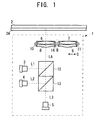
- FIG. 1 shows an optical pickup with a recording medium in the embodiment of the present invention.
- an optical pickup 1 reproduces or records information with respect to a plurality of types of recording media (2).
- the types of the recording media on which the information can be recorded or reproduced by the optical pickup of the present invention There is no limitation in the types of the recording media on which the information can be recorded or reproduced by the optical pickup of the present invention. Since it is required to selectively record and reproduce the information by using one optical pickup, a certain degree of commonness is required for the plurality of types of recording media.
- the recording media is optical recording media in which recording or reproduction of information is carried out by an optical device, that there is identity or similarity in the external shape of the recording media, and the like.
- the optical pickup 1 which can record or reproduce the information with respect to four types in total of the recording media, which are the CD, the DVD, the Blu-ray Disc, and the HD-DVD.
- the wavelength of a light beam used for the CD is 780 nm
- the numerical aperture (NA) to be set for an object lens is 0.45
- the thickness of a cover layer (2A) is 1.2 mm
- its track pitch is 1.6 ⁇ m.
- the wavelength of a light beam used for the DVD is 650 nm
- the NA to be set for an object lens is 0.6
- the thickness of a cover layer is 0.6 mm
- its track pitch is 0.74 ⁇ m.
- the wavelength of a light beam used for the Blu-ray Disc is 405 nm
- the NA to be set for an object lens is 0.85
- the thickness of a cover layer is 0.1 mm
- its track pitch is 0.32 ⁇ m.
- the wavelength of the light beam, the NA, the thickness of the cover layer and the track pitch with respect to these recording media are determined as the standard.
- the wavelength of a light beam used for the HD-DVD is 405 nm
- the NA to be set for an object lens is 0.6
- the thickness of a cover layer is 0.65 mm
- its track pitch is 0.34 ⁇ m. Comparing the Blu-ray Disc and the HD-DVD, the wavelengths of the light beams are equal. However, the thicknesses of their cover layers are mutually different.
- the optical pickup 1 is provided with: a light source 3 for outputting a light beam L1 of a wavelength of 780 nm; a light source 4 for outputting a light beam L2 of a wavelength of 650 nm; and a light source 5 for outputting a light beam L3 of a wavelength of 405 nm.
- a light source 3 for outputting a light beam L1 of a wavelength of 780 nm
- a light source 4 for outputting a light beam L2 of a wavelength of 650 nm
- a light source 5 for outputting a light beam L3 of a wavelength of 405 nm.
- the optical pickup 1 is provided with the three light sources 3, 4, and 5.
- the number of light sources may be equal to or greater than four, in the optical pickup of the present invention. Namely, if there are five or more types of recording media that are record and reproduction objects and there are four or more types of wavelengths in the light beam, it is possible to increase the number of light sources, depending on the
- the optical pickup 1 is provided with object lenses 6 and 7 which have mutually different optical properties.
- object lens 6 such an optical property that is appropriate for record or reproduction of the information with respect to the Blu-ray Disc by using the light beam L3 is set.
- the optical property of the object lens 6 is set not to cause spherical aberration when the light beam L3 is converged on a recording surface of the Blu-ray Disc by the object lens 6.
- object lens 7 such an optical property that is appropriate for record or reproduction of the information with respect to the HD-DVD by using the light beam L3 is set.
- the optical property of the object lens 7 is set not to cause spherical aberration when the light beam L3 is converged on a recording surface of the HD-DVD by the object lens 7.
- the above-described optical properties are set for the object lenses 6 and 7, however, the present invention is not limited to this embodiment.
- the optical properties to be set for the two object lenses can be set in accordance with the types and combination of the recording media on which the information is to be recorded or reproduced by using the optical pickup.
- the optical pickup 1 is provided with optical elements 8 and 9.
- the optical element 8 is unified with the object lens 6, and has such an optical property that a phase difference distribution is given to the light beam L2 but not to given to the light beam L3.
- the optical element 9 is unified with the object lens 7, and has such an optical property that a phase difference distribution is given to the light beam L1 but not to given to the light beam L3.
- the above-described optical properties are set for the optical elements 8 and 9, however, the present invention is not limited to this embodiment.
- the optical element 8 it is possible to set such an optical property that a phase difference distribution is given to the light beam L3 but not to given to the light beam L2.
- optical element 9 it is possible to set such an optical property that a phase difference distribution is given to the light beam L3 but not to given to the light beam L1. It is also possible to set such an optical property that phase different distributions, which are mutually different, are given to both the light beams L1 and L3.
- the optical properties of the optical elements 8 and 9 are not limited to such a property that a phase difference distribution is given to a particular light beam, but may be such a property that another optical change is given to a particular light beam. For example, it may be such a property that a part of light is shielded to perform aperture limitation, or that a transmittance distribution is changed for an intensity distribution change.
- FIG. 2 shows a condition in which the optical element 8 and the object lens 6 are connected by a support member 10.
- the optical element 8 is an optical member different from the object lens 6.
- the optical element 8 is made of a light transmitting material, such as glass and plastic, for example.
- the optical element 8 is connected to the object lens 6 via the support member 10.
- the optical element 9 is an optical member different from the object lens 7, and is made of a light transmitting material, such as glass and plastic, for example.
- the optical element 9 is connected to the object lens 7 via a support member 11.
- each optical element in the optical pickup of the present invention is not limited to the structure shown in FIG. 2.
- FIG. 4 shows magnified one portion of the optical element 8.
- a plurality of steps 8A, 8B, ... are formed.
- the steps 8A, 8B, ... individually have a circular external shape, and are placed concentrically on the basis of the central portion of the optical element 8 through which the common optical axis LA (cf. FIG. 1) passes.
- a height H of each step 8A, 8B, .... is set to generate an optical path length difference which is an integral multiple of the wavelength of the light beam L3.
- the optical element 8 transmits the light beam L3 without giving a phase difference distribution.
- each step is designed to give a phase difference distribution to the light beam L2 and correct spherical aberration caused when the light beam L2 is converged on the recording surface of the DVD only by the object lens 6.
- the optical element 9 a plurality of steps are formed, as in the optical element 8.
- a height of each step is set to generate an optical path length difference which is an integral multiple of the wavelength of the light beam L3.
- the height, other shapes and placement of each step of the optical element 9 are designed to give a phase difference distribution to the light beam L1 and correct spherical aberration caused when the light beam L1 is converged on the recording surface of the CD only by the object lens 7.
- the method of realizing the optical property in each optical element is not limited to the above-described circular steps.
- the basic function required for the optical element is to select one type of light beam out of two or more types of light beams, by using the fact that the two or more types of light beams have mutually different wavelengths, and to perform a particular optical treatment with respect to the selected type of light beam. If capable of realizing such a function, the method using a hologram in another form, wavelength-selective aperture limitation, a diffraction granting, or the like may be adopted.
- the optical pickup 1 is further provided with dichroic prisms 12 and 13.
- the dichroic prism 12 reflects the light beam L1 and transmits the light beams L2 and L3.
- the dichroic prism 13 reflects the light beam L2 and transmits the light beam L3.
- the dichroic prisms 12 and 13 are optical axis converting devices for converting the optical axis of each of the light beams L1, L2, and L3 to one common optical axis LA.
- the optical axis converting device is not limited to the dichroic prism, and various prisms or mirrors can be used.
- the optical pickup 1 is provided with an object lens changing device 14.
- the object lens changing device 14 is a changing device for changing the placement of the object lenses 6 and 7 so as to place either the object lens 6 or the object lens 7 at a predetermined position through which the common optical axis LA passes.
- the optical element 8 and the object lens 6 are connected with each other and form a single-piece construction, as the object lens 6 is placed by the object lens changing device 14 at a predetermined position through which the common optical axis LA passes, the optical element 8 is also placed at a predetermined position through which the common optical axis LA passes.
- the optical element 9 and the object lens 7 are connected with each other and form a single piece construction, as the object lens 7 is placed by the object lens changing device 14 at a predetermined position through which the common optical axis LA passes, the optical element 9 is also placed at a predetermined position through which the common optical axis LA passes.
- the operation of the optical pickup 1 will be explained below.
- the object lens 6 and the optical element 8 are placed by the object lens changing device 14 at predetermined positions through which the common optical axis LA passes.
- the light source 4 is driven, to output the light beam L2 from the light source 4.
- the light axis of the light beam L2 is set to the common light axis LA by the dichroic prism 13.
- the light beam L2 is transmitted through the dichroic prism 12, the optical element 8, and the object lens 6 in order, and reaches to the recording surface of the DVD (the recording medium 2).
- the object lens 6 such an optical property that is appropriate for record or reproduction of the information with respect to the Blu-ray Disc by using the light beam L3 is set.
- the light beam L2 is transmitted only through the object lens 6 and reaches to the recording surface of the DVD, spherical aberration occurs on the recording surface of the DVD.
- the light beam L2 is transmitted through the optical element 8 and then the object lens 6, and reaches to the recording surface of the DVD.
- a phase difference distribution is given to the light beam L2 by the optical element 8.
- the spherical aberration on the recording surface of the DVD is corrected to be in a range appropriate for record or reproduction of the information with respect to the DVD.
- the object lens 6 and the optical element 8 are placed by the object lens changing device 14 at predetermined positions through which the common optical axis LA passes. Then, the light source 5 is driven, to output the light beam L3 from the light source 5. By this, the light beam L3 is transmitted through the dichroic prisms 12 and 13, and consequently, the light axis of the light beam L3 matches the common light axis LA. Then, the light beam L3 is transmitted through the optical element 8 and the object lens 6 in order, and reaches to the recording surface of the Blu-ray Disc (the recording medium 2). The optical element 8 transmits the light beam L3 without giving a phase difference distribution.
- the object lens 6 such an optical property that is appropriate for record or reproduction of the information with respect to the Blu-ray Disc by using the light beam L3 is set.
- the light beam L3 appropriately converges on the recording surface of the Blu-ray Disc.
- the object lens 7 and the optical element 9 are placed by the object lens changing device 14 at predetermined positions through which the common optical axis LA passes. Then, the light source 3 is driven, to output the light beam L1 from the light source 3. By this, the light axis of the light beam L1 is set to the common light axis LA by the dichroic prism 12. The light beam L1 is transmitted through the optical element 9 and the object lens 7 in order, and reaches to the recording surface of the CD (the recording medium 2). For the object lens 7, such an optical property that is appropriate for record or reproduction of the information with respect to the HD-DVD by using the light beam L3 is set.
- the light beam L1 is transmitted only through the object lens 7 and reaches to the recording surface of the CD, spherical aberration occurs on the recording surface of the CD.
- the light beam L1 is transmitted through the optical element 9 and then the object lens 7, and reaches to the recording surface of the CD.
- a phase difference distribution is given to the light beam L1 by the optical element 9.
- the spherical aberration on the recording surface of the CD is corrected to be in a range appropriate for record or reproduction of the information with respect to the CD.
- the object lens 7 and the optical element 9 are placed by the object lens changing device 14 at predetermined positions through which the common optical axis LA passes. Then, the light source 5 is driven, to output the light beam L3 from the light source 5. By this, the light beam L3 is transmitted through the dichroic prisms 12 and 13, and consequently, the light axis of the light beam L3 matches the common light axis LA. Then, the light beam L3 is transmitted through the optical element 9 and the object lens 7 in order, and reaches to the recording surface of the HD-DVD (the recording medium 2). The optical element 9 transmits the light beam L3 without giving a phase difference distribution. For the object lens 7, such an optical property that is appropriate for record or reproduction of the information with respect to the HD-DVD by using the light beam L3 is set. As a result, the light beam L3 appropriately converges on the recording surface of the HD-DVD.
- the optical pickup 1 it is possible to appropriately converge the light beam L2 on the recording surface of the DVD, and appropriately converge the light beam L3 on the recording surface of the Blu-ray Disc, by using the object lens 6 and the optical element 8. Moreover, it is possible to appropriately converge the light beam L1 on the recording surface of the CD, and appropriately converge the light beam L3 on the recording surface of the HD-DVD, by using the object lens 7 and the optical element 9. Then, it is possible to record or reproduce the information with respect to the four types of recording media, by using the three types of light beams, by changing the combination of the object lens 6 and the optical element 8 and the combination of the object lens 7 and the optical element 9.
- this type of optical element is provided with a function of selecting one type of light beam, out of two or more types of light beams, by using the fact that the two or more types of light beams have mutually different wavelengths, and a function of performing a particular optical treatment with respect to the selected type of light beam.
- the Blu-ray Disc and the HD-DVD if the information is recorded or reproduced with respect to the two or more types of recording media which have the cover layers of different thicknesses while the light beams to be used have the same wavelength, it is difficult to correct all of the spherical aberration caused on the recording surface of each recording medium, by using a single optical element. Namely, as in the Blu-ray Disc and the HD-DVD, if the wavelengths of the light beams are equal (405 nm) but the thicknesses of the cover layers are mutually different (0.1 mm, 0.65 mm), the spherical aberration on the recording surface varies in the two types of recording media.
- optical treatments for the two types of recording media (i.e. to change the optical property of the light beam between two types of recording media).
- “to perform different optical treatments” includes such a case that the optical treatment is performed with respect to the light beam for one type of recording medium, while the optical treatment is not performed with respect to the light beam for the other type of recording medium.
- the wavelengths of the light beams are equal, it is hardly possible to perform the different optical treatments with respect to the light beams in the two types of recording media, by using a single optical element.
- the optical pickup 1 in the embodiment of the present invention is provided with: the two object lenses 6 and 7; and the two optical elements 8 and 9.
- the optical pickup 1 in the embodiment of the present invention is provided with: the two object lenses 6 and 7; and the two optical elements 8 and 9.
- the optical pickup 1 in the embodiment of the present invention can realize the record or reproduction of the information with respect to the four types of recording media, by changing the two object lenses 6 and 7 (and the two optical elements 8 and 9). By this, it is possible to reduce the size, weight, and number of parts of the optical pickup for the multi drive, which can handle the four types of recording media.
- the object lens 6 and the optical element 8 are assigned to the DVD and the Blu-ray Disc
- the object lens 7 and the optical element 9 are assigned to the CD and the HD-DVD.
- a proper hologram or diffraction granting such as steps, is formed on the optical element.
- a difference in the thickness of the cover layer between the two types of recording media becomes smaller, it is easier to form the hologram or diffraction granting.
- a difference in the thickness of the cover layer between the two types of recording media becomes smaller, it is possible to reduce the height of each step more greatly.
- Ease to form the hologram or diffraction granting increases reliability of highly accurate correction of spherical aberration. Therefore, in the two types of recording media to be assigned to one optical element, it is desirable that a difference in the thickness of the cover layer between them is small.
- a difference in the thickness of the cover layer between the DVD and the Blu-ray Disc is 0.5 mm, which is relatively small.
- a difference in the thickness of the cover layer between the CD and the HD-DVD is 0.55 mm, which is relatively small.
- a difference in the thickness of the cover layer between the Blu-ray Disc and the CD is 1.1 mm, which is relatively large.
- the assignment method of assigning the optical elements 8 and 9 is considered so as to satisfy the following two conditions: (1) different optical elements are to be assigned to the Blu-ray Disc and the HD-DVD because the light beams to be used have the same wavelength; and (2) a difference in the thickness of the cover layer is desirably small between two types of recording media which are to be assigned to one optical element. It is desirable, as in the embodiment of the present invention, that the optical element 8 is assigned to the DVD and the Blu-ray Disc and that the optical element 9 is assigned to the CD and the HD-DVD.
- the technological idea of the present invention can be embodied as the optical pickup 1 as described above, but can be embodied as a recording / reproducing apparatus equipped with such an optical pickup.
- the "recording / reproducing apparatus” indicates an apparatus having a function of recording information onto a recording medium, an apparatus having a function of reproducing the information recorded on the recording medium, or an apparatus having a function of recording and reproducing the information with respect to the recording medium.
- the recording / reproducing apparatus in which the technological idea of the present invention is embodied, it is possible to realize record or reproduction of the information with respect to a plurality of types of recording media by using one recording / reproducing apparatus. Moreover, by using two or more object lenses and two or more optical elements, it is possible to appropriately record or reproduce the information with respect to various recording media, even if several types of recording media that are record objects or reproduction objects include two or more types of recording media which have different optical properties such as different thicknesses of cover layers while the light beams to be used for them have the same wavelength.
- the information can be recorded or reproduced with respect to four or more types of recording media by changing the two ore more object lenses, it is possible to reduce the size, weight, and number of parts of the recording / reproducing apparatus. Moreover, if one optical element is assigned to the DVD and the Blu-ray Disc, and if the other optical element is assigned to the CD and the HD-DVD, it is possible to improve the record and reproduction abilities of the information with respect to the individual recording media.
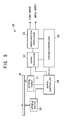
- FIG. 5 shows a multi disk player in the example of the present invention.
- a multi disk player 50 has a function of reproducing information recorded on the four types of recording media, such as the CD, the DVD, the Blu-ray Disc, and the HD-DVD.
- the multi disk player 50 is provided with: an optical pickup 51; a signal processor 52; a reproduction processor 53; a servo controller 54; a spindle motor 55; and a system controller 56.
- the optical pickup 51 reads the information recorded on the CD, the DVD, the Blu-ray Disc, or the HD-DVD (a recording medium 30 in FIG. 5), and outputs a read signal corresponding to the read information, to the signal processor 52.
- the signal processor 52 On the basis of the read signal outputted from the optical pickup 51, the signal processor 52 generates a Radio Frequency (RF) signal and a servo control signal.
- RF Radio Frequency
- the reproduction processor 53 reproduces the information recorded on the CD, the DVD, the Blu-ray Disc, or the HD-DVD.
- the servo controller 54 performs tracking servo and focus servo in the optical pitkup 51, and performs rotation control of the spindle motor 55.
- the spindle motor 55 controls a rotational speed of the recording medium 30, under the control of the servo controller 54.
- the system controller 56 performs overall control of the multi disk player 50. In particular, the system controller 56 detects the type of the recording medium 30 mounted on a disk mount (not-illustrated), controls an object lens changing mechanism 73 (refer to FIG. 6) in accordance with the type of the recording medium 30, and controls a changeover between an object lens 69 and an object lens 70.
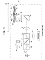
- FIG. 6 shows the internal structure of the optical pickup 51.
- the optical pickup 51 is provided with: three semiconductor lasers 61, 62, and 63; two dichroic prisms 64 and 65; a collimator lens 66; a rising mirror 67; a broadband quarter-wavelength plate 68; the two object lenses 69 and 70; two optical elements 71 and 72; the object lens changing mechanism 73; a deflection beam splitter 74; a detection lens 75; and a photodetector 76.
- the semiconductor laser 61 outputs a light beam L11 of a wavelength of 780 nm. This is a light beam used for reproduction of the information recorded on the CD.
- the semiconductor laser 62 outputs a light beam L12 of a wavelength of 650 nm. This is a light beam used for reproduction of the information recorded on the DVD.
- the semiconductor laser 63 outputs a light beam L13 of a wavelength of 405 nm. This is a light beam used for reproduction of the information recorded on the Blu-ray Disc or the HD-DVD.
- the dichroic prism 64 reflects the light beam L11 and transmits the light beams L12 and L13.
- the dichroic prism 65 reflects the light beam L12 and transmits the light beam L13.
- the collimator lens 66 produces a parallel bundle of rays from the light beam L11, L12, or L13.
- the rising mirror 67 leads the light beam L11, L12, or L13, which is transmitted through the collimator lens 66, to the object lens 69 or 70 side, and leads reflected light to the deflection beam splitter 74 side.
- the broadband quarter-wavelength plate 68 functions as a quarter-wavelength plate throughout a broadband from wavelengths of 405 to 780 nm. Namely, the broadband quarter-wavelength plate 68 performs a process of converting linear polarization to circular polarization on the light beams L11, L12, and L13, which is outputted from the semiconductor laser 61, 62, and 63, respectively. Moreover, the broadband quarter-wavelength plate 68 performs a process of converting circular polarization to linear polarization on the reflected light.
- the object lens 69 is used in reproduction of the information recorded on the DVD or the Blu-ray Disc.
- the optical property of the object lens 69 is set not to cause spherical aberration when the light beam L13 is converted on the recording surface of the Blu-ray Disc by the object lens 69.
- the object lens 70 is used in reproduction of the information recorded on the CD or the HD-DVD.
- the optical property of the object lens 70 is set not to cause spherical aberration when the light beam L13 is converted on the recording surface of the HD-DVD by the object lens 70.
- the optical element 71 is unified with the object lens 69, and has such an optical property that a phase difference distribution is given to the light beam L12 but not given to the light beam L13. Specifically, a plurality of circular steps are formed on a surface of the optical element 71, to transmit the light beam L13 without giving a phase difference distribution thereto, give a phase difference distribution to the light beam L12, and correct spherical aberration caused when the light beam L12 is converged on the recording surface of the DVD only by the object lens 69. Moreover, the optical element 71 is connected and fixed to the object lens 69 via a support member 77.
- the optical element 72 is unified with the object lens 70, and has such an optical property that a phase difference distribution is given to the light beam L11 but not given to the light beam L13. Specifically, a plurality of circular steps are formed on a surface of the optical element 72, to transmit the light beam L13 without giving a phase difference distribution thereto, give a phase difference distribution to the light beam L11, and correct spherical aberration caused when the light beam L11 is converged on the recording surface of the CD only by the object lens 70. Moreover, the optical element 72 is connected and fixed to the object lens 70 via a support member 78.
- the object lens changing mechanism 73 changes the placement of the object lenses 69 and 70 so as to place either the object lens 69 or the object lens 70 at a predetermined position through which the common optical axis LA1 passes. By rotating around a rotation axis B1, the object lens changing mechanism 73 changes the placement of the object lenses 69 and 70.
- the deflection beam splitter 74 transmits the light beam L1, L2, and L3, outputted from the semiconductor laser 61, 62, and 63, respectively, to the object lens 69 or 70 side. At the same time, the deflection beam splitter 74 leads the reflected light, which is obtained by reflection of the light beam on the recording surface of the recording medium 30, to the photodetector 76 side.
- the photodetector 76 is provided with a four division light receiving element, for example, and outputs an electric signal corresponding to an intensity distribution of the reflected light inputted through the detection lens 75, as a read signal.
- the object lens changing device 73 is driven, to place the object lens 69 and the optical element 71 at predetermined positions through which the common optical axis LA1 passes.
- the semiconductor laser 62 is driven, to output the light beam L12 from semiconductor laser 62.
- the direction of the light beam L12 is changed by the dichroic prism 65.
- the light beam L12 is transmitted through the dichroic prism 64, the deflection beam splitter 74, and collimator lens 66.
- the direction of the light beam L12 is changed by the rising mirror 67.
- the optical axis of the light beam L12 matches the common optical axis LA1.
- the light beam L12 is transmitted through the broadband quarter-wavelength plate 68, the optical element 71, and the object lens 69 in order, and reaches to the recording surface of the DVD (the recording medium 30).
- the optical property of the object lens 69 is set not to cause spherical aberration when the light beam L13 is converged on the recording surface of the Blu-ray Disc.
- the plurality of circular steps are formed on the surface of the optical element 71, to give a phase difference distribution to the light beam L12, and correct the spherical aberration caused when the light beam L12 is converged on the recording surface of the DVD only by the object lens 69.
- the light beam L12 which is transmitted through the optical element 71 and the object lens 69 and reaches to the recording surface to the DVD, can be appropriately converged on the recording surface of the DVD, and the spherical aberration can be controlled in a range appropriate for reproduction of the information recorded on the recording surface of the DVD.
- the light beam L12 converged on the recording surface of the DVD is reflected by this recording surface. Then, the reflected light of the light beam L12 is transmitted through the object lens 69, the optical element 71, the broadband quarter-wavelength plate 68, and the like, and reaches to the deflection beam splitter 74. Then, the reflected light is transmitted from the deflection beam splitter 74 to the detection lens 75, inputted to the photodetector 76, and converted to a read signal by the photodetector 76. Then, the read signal is supplied to the signal processor 52.
- the object lens changing device 73 is driven, to place the object lens 69 and the optical element 71 at predetermined positions through which the common optical axis LA1 passes.
- the semiconductor laser 63 is driven, to output the light beam L13 from semiconductor laser 63.
- the light beam L13 is transmitted through the dichroic prisms 65 and 64, the deflection beam splitter 74, and collimator lens 66.
- the direction of the light beam L13 is changed by the rising mirror 67.
- the optical axis of the light beam L13 matches the common optical axis LA1.
- the light beam L13 is transmitted through the broadband quarter-wavelength plate 68, the optical element 71, and the object lens 69 in order, and reaches to the recording surface of the Blu-ray Disc (the recording medium 30).
- the optical property of the object lens 69 is set not to cause spherical aberration when the light beam L13 is converged on the recording surface of the Blu-ray Disc.
- the optical element 71 transmits the light beam L13 without phase conversion. As a result, the light beam L13, which is transmitted through the optical element 71 and the object lens 69 and reaches to the recording surface to the Blu-ray Disc, can be appropriately converged on the recording surface of the Blu-ray Disc.
- the light beam L13 converged on the recording surface of the Blu-ray Disc is reflected by this recording surface. Then, the reflected light of the light beam L13 is inputted to the photodetector 76 through the same route as that in the reflected light of the light beam L12, and converted to a read signal by the photodetector 76. Then, the read signal is supplied to the signal processor 52.
- the object lens changing device 73 is driven, to place the object lens 70 and the optical element 72 at predetermined positions through which the common optical axis LA1 passes.
- the semiconductor laser 61 is driven, to output the light beam L11 from semiconductor laser 61.
- the direction of the light beam L11 is changed by the dichroic prism 64.
- the light beam L11 is transmitted through the deflection beam splitter 74 and collimator lens 66.
- the direction of the light beam L11 is changed by the rising mirror 67.
- the optical axis of the light beam L11 matches the common optical axis LA1.
- the light beam L11 is transmitted through the broadband quarter-wavelength plate 68, the optical element 72, and the object lens 70 in order, and reaches to the recording surface of the CD (the recording medium 30).
- the optical property of the object lens 70 is set not to cause spherical aberration when the light beam L13 is converged on the recording surface of the HD-DVD.
- the plurality of circular steps are formed on the surface of the optical element 72, to give a phase difference distribution to the light beam L11, and correct the spherical aberration caused when the light beam L11 is converged on the recording surface of the CD only by the object lens 70.
- the light beam L11 which is transmitted through the optical element 72 and the object lens 70 and reaches to the recording surface to the CD, can be appropriately converged on the recording surface of the CD, and the spherical aberration can be controlled in a range appropriate for reproduction of the information recorded on the recording surface of the CD.
- the light beam L11 converged on the recording surface of the CD is reflected by this recording surface. Then, the reflected light of the light beam L11 is transmitted through the object lens 70, the optical element 72, the broadband quarter-wavelength plate 68, and the like, and reaches to the deflection beam splitter 74. Then, the reflected light is transmitted from the deflection beam splitter 74 to the detection lens 75, inputted to the photodetector 76, and converted to a read signal by the photodetector 76. Then, the read signal is supplied to the signal processor 52.
- the object lens changing device 73 is driven, to place the object lens 70 and the optical element 72 at predetermined positions through which the common optical axis LA1 passes.
- the semiconductor laser 63 is driven, to output the light beam L13 from semiconductor laser 63.
- the light beam L13 is transmitted through the dichroic prisms 65 and 64, the deflection beam splitter 74, and collimator lens 66.
- the direction of the light beam L13 is changed by the rising mirror 67.
- the optical axis of the light beam L13 matches the common optical axis LA1.
- the light beam L13 is transmitted through the broadband quarter-wavelength plate 68, the optical element 72, and the object lens 70 in order, and reaches to the recording surface of the HD-DVD (the recording medium 30).
- the optical property of the object lens 70 is set not to cause spherical aberration when the light beam L13 is converged on the recording surface of the HD-DVD.
- the optical element 72 transmits the light beam L13 without phase conversion. As a result, the light beam L13, which is transmitted through the optical element 72 and the object lens 70 and reaches to the recording surface to the HD-DVD, can be appropriately converged on the recording surface of the HD-DVD.
- the light beam L13 converged on the recording surface of the HD-DVD is reflected by this recording surface.
- the reflected light of the light beam L13 is inputted to the photodetector 76 through the same route as that in the reflected light of the light beam L11, and converted to a read signal by the photodetector 76. Then, the read signal is supplied to the signal processor 52.
- the multi disk player 50 it is possible to appropriately converge the light beam L12 on the recording surface of the DVD, and appropriately converge the light beam L13 on the recording surface of the Blu-ray Disc, by using the object lens 69 and the optical element 71 of the optical pickup 51. Moreover, it is possible to appropriately converge the light beam L11 on the recording surface of the CD, and appropriately converge the light beam L13 on the recording surface of the HD-DVD, by using the object lens 70 and the optical element 72. Then, it is possible to record or reproduce the information with respect to the four types of recording media, by using the three types of light beams, by changing the combination of the object lens 69 and the optical element 71 and the combination of the object lens 70 and the optical element 72.
Landscapes
- Physics & Mathematics (AREA)
- Optics & Photonics (AREA)
- Optical Head (AREA)
Abstract
Description
Claims (15)
- An optical pickup (1, 51) for reproducing or recording information with respect to a plurality of types of recording media (2), characterized in that said optical pickup comprises:a first light source (3, 61) for outputting a first light beam (L1) of a first wavelength;a second light source (4, 62) for outputting a second light beam (L2) of a second wavelength;a third light source (4, 63) for outputting a third light beam (L3) of a third wavelength;a first object lens (6, 69) and a second object lens (7, 70), having mutually different optical properties;a first optical element (8, 71), unified with said first object lens, for transmitting either one of said first light beam and said third light beam without changing its optical property, and changing the other's optical property; anda second optical element (9, 72), unified with said second object lens, for transmitting either one of said second light beam and said third light beam without changing its optical property, and changing the other's optical property.
- The optical pickup (1, 51) according to claim 1 characterized in that said first optical element (8, 71) does not give a phase difference distribution to either one of said first light beam (L1) and said third light beam (L3), but gives a phase difference distribution to the other.
- The optical pickup (1, 51) according to claim 1 characterized in that said first optical element (8, 71) is a hologram element.
- The optical pickup (1, 51) according to claim 1 characterized in that said first optical element (8, 71) is a wavelength-selective aperture limitation element.
- The optical pickup (1, 51) according to any one of claims 1 to 4 characterized in that said first optical element (8, 71) is an optical member different from said first object lens (6, 69) and is connected to said first object lens via a first support member (10, 77).
- The optical pickup (1, 51) according to any one of claims 1 to 4 characterized in that said first optical element (22) is formed on said first object lens (21).
- The optical pickup (1, 51) according to any one of claims 1 to 6 characterized in that said second optical element (9, 72) does not give a phase difference distribution to either one of said second light beam (L2) and said third light beam (L3), but gives a phase difference distribution to the other.
- The optical pickup (1, 51) according to any one of claims 1 to 6 characterized in that said second optical element (9, 72) is a hologram element.
- The optical pickup (1, 51) according to any one of claims 1 to 6 characterized in that said second optical element (9, 72) is a wavelength-selective aperture limitation element.
- The optical pickup (1, 51) according to any one of claims 1 to 9 characterized in that said second optical element (9, 72) is an optical member different from said second object lens (7, 70) and is connected to said second object lens via a second support member (11, 78).
- The optical pickup (1, 51) according to any one of claims 1 to 9 characterized in that said second optical element (22) is formed on said second object lens (21).
- The optical pickup (1, 51) according to any one of claims 1 to 11 characterized in that said optical pickup further comprises:an optical axis converting device (12, 13, 65, 64) for converting an optical axis of each of said first light beam (L1), said second light beam (L2), and third light beam (L3), to one common optical axis (LA, LA1); anda changing device (14, 73) for changing placement of said first object lens (6, 69) and said second object lens (7, 70) so as to place either one of said first object lens and said second object lens at a predetermined position through which the common optical axis passes.
- The optical pickup (1, 51) according to any one of claims 1 to 12 characterized in thatthe first wavelength of said first light beam (L1) is appropriate for record or reproduction of the information, with respect to a first recording medium having a cover layer of a thickness of T1 and a track pitch of P1,the second wavelength of said second light beam (L2) is appropriate for record or reproduction of the information, with respect to a second recording medium having a cover layer of a thickness of T2 (T2 < T1) and a track pitch of P2, andthe third wavelength of said third light beam (L3) is appropriate for record or reproduction of the information, with respect to a third recording medium having a cover layer of a thickness of T3 (T3 < T2) and a track pitch of P3 and a fourth recording medium having a cover layer of a thickness of T2 and a track pitch of P4.
- The optical pickup (1, 51) according to claim 13 characterized in thatthe first recording medium is a compact disc,the second recording medium is a DVD, andthe third recording medium is a blu-ray disc.
- A recording / reproducing apparatus (50) for reproducing or recording information with respect to a plurality of types of recording media (2), characterized in that said recording / reproducing apparatus comprises an optical pickup (1, 51) for reproducing or recording the information with respect to the plurality of types of recording media (2), and
said optical pickup comprises:a first light source (3, 61) for outputting a first light beam (L1) of a first wavelength;a second light source (4, 62) for outputting a second light beam (L2) of a second wavelength;a third light source (4, 63) for outputting a third light beam (L3) of a third wavelength;a first object lens (6, 69) and a second object lens (7, 70), having mutually different optical properties;a first optical element (8, 71), unified with said first object lens, for transmitting either one of said first light beam and said third light beam without changing its optical property, and changing the other's optical property; anda second optical element (9, 72), unified with said second object lens, for transmitting either one of said second light beam and said third light beam without changing its optical property, and changing the other's optical property.
Applications Claiming Priority (2)
| Application Number | Priority Date | Filing Date | Title |
|---|---|---|---|
| JP2004015884A JP2005209299A (en) | 2004-01-23 | 2004-01-23 | Optical pickup and recording reproducing device |
| JP2004015884 | 2004-01-23 |
Publications (2)
| Publication Number | Publication Date |
|---|---|
| EP1557829A2 true EP1557829A2 (en) | 2005-07-27 |
| EP1557829A3 EP1557829A3 (en) | 2007-01-10 |
Family
ID=34631952
Family Applications (1)
| Application Number | Title | Priority Date | Filing Date |
|---|---|---|---|
| EP05001116A Withdrawn EP1557829A3 (en) | 2004-01-23 | 2005-01-20 | Optical pickup and recording/reproducing apparatus |
Country Status (4)
| Country | Link |
|---|---|
| US (1) | US20050163015A1 (en) |
| EP (1) | EP1557829A3 (en) |
| JP (1) | JP2005209299A (en) |
| CN (1) | CN1649006A (en) |
Cited By (1)
| Publication number | Priority date | Publication date | Assignee | Title |
|---|---|---|---|---|
| EP1761922B1 (en) * | 2004-06-18 | 2009-03-04 | Koninklijke Philips Electronics N.V. | System and method of objective lens selection in a multiple lens actuator |
Families Citing this family (20)
| Publication number | Priority date | Publication date | Assignee | Title |
|---|---|---|---|---|
| JP2007128654A (en) * | 2004-04-08 | 2007-05-24 | Konica Minolta Opto Inc | Multi-focal object lens, optical pickup device and optical information recording/reproducing device |
| JP4437731B2 (en) * | 2004-10-08 | 2010-03-24 | フジノン株式会社 | Optical pickup optical system and optical pickup device using the same |
| JP2006202416A (en) * | 2005-01-20 | 2006-08-03 | Konica Minolta Opto Inc | Optical pickup device |
| KR100694097B1 (en) * | 2005-04-01 | 2007-03-12 | 삼성전자주식회사 | Optical pickup and optical recording and / or reproducing apparatus using the same, and tracking error signal detection method |
| US7352517B2 (en) * | 2005-05-09 | 2008-04-01 | Konica Minolta Opto, Inc. | Optical pickup apparatus |
| KR20080056716A (en) * | 2005-09-27 | 2008-06-23 | 코니카 미놀타 옵토 인코포레이티드 | Optical pickup device and optical information recording medium recording and reproducing device |
| JP4785861B2 (en) * | 2005-10-18 | 2011-10-05 | 三菱電機株式会社 | Optical head device and optical disk device |
| JP3972959B2 (en) * | 2005-11-08 | 2007-09-05 | コニカミノルタオプト株式会社 | Optical pickup device |
| KR20080066009A (en) * | 2005-11-08 | 2008-07-15 | 코니카 미놀타 옵토 인코포레이티드 | Optical pickup |
| WO2007080925A1 (en) * | 2006-01-12 | 2007-07-19 | Matsushita Electric Industrial Co., Ltd. | Optical pickup device and information processor provided with such optical pickup device |
| JP4499671B2 (en) * | 2006-02-17 | 2010-07-07 | シャープ株式会社 | Optical pickup device |
| KR101055342B1 (en) | 2006-04-26 | 2011-08-09 | 가부시키가이샤 리코 | Optical pickup and optical information processing device |
| US20070297313A1 (en) * | 2006-06-23 | 2007-12-27 | Nobuhiro Konuma | Optical pickup |
| US20080019232A1 (en) * | 2006-07-21 | 2008-01-24 | Samsung Electronics Co., Ltd. | Object lens and optical pick-up device having the same |
| KR100903143B1 (en) * | 2006-07-21 | 2009-06-16 | 삼성전자주식회사 | Object lens and optical pick-up apparatus having the same |
| KR20080017807A (en) * | 2006-08-22 | 2008-02-27 | 삼성전자주식회사 | Optical pickup |
| US8385169B2 (en) * | 2006-12-29 | 2013-02-26 | Panasonic Corporation | Optical disc drive and optical information system |
| JP2008217882A (en) * | 2007-03-02 | 2008-09-18 | Matsushita Electric Ind Co Ltd | Optical pickup and optical disc apparatus, computer, optical disc player, optical disc recorder |
| JP2010061764A (en) | 2008-09-05 | 2010-03-18 | Ricoh Co Ltd | Optical element |
| CN101807425B (en) * | 2010-03-25 | 2013-01-09 | 清华大学深圳研究生院 | Blue light optical head |
Family Cites Families (6)
| Publication number | Priority date | Publication date | Assignee | Title |
|---|---|---|---|---|
| US6304540B1 (en) * | 1998-03-30 | 2001-10-16 | Samsung Electronics Co., Ltd. | Optical pickup compatible with a digital versatile disk and a recordable compact disk using a holographic ring lens |
| US6343058B1 (en) * | 1997-10-30 | 2002-01-29 | Ricoh Company, Ltd. | Optical pickup device applicable to two kinds of recording media with minimized deterioration of a beam spot |
| KR19990074812A (en) * | 1998-03-14 | 1999-10-05 | 윤종용 | Compatible optical pickup device |
| JP3827860B2 (en) * | 1998-03-31 | 2006-09-27 | パイオニア株式会社 | Objective lens and optical pickup device |
| EP1647016A2 (en) * | 2003-07-07 | 2006-04-19 | Matsushita Electric Industrial Co., Ltd. | Objective lens, optical pick-up device, and optical disk device |
| JP2005071462A (en) * | 2003-08-22 | 2005-03-17 | Victor Co Of Japan Ltd | Optical pickup device |
-
2004
- 2004-01-23 JP JP2004015884A patent/JP2005209299A/en active Pending
-
2005
- 2005-01-20 EP EP05001116A patent/EP1557829A3/en not_active Withdrawn
- 2005-01-21 US US11/038,418 patent/US20050163015A1/en not_active Abandoned
- 2005-01-21 CN CNA2005100046896A patent/CN1649006A/en active Pending
Cited By (1)
| Publication number | Priority date | Publication date | Assignee | Title |
|---|---|---|---|---|
| EP1761922B1 (en) * | 2004-06-18 | 2009-03-04 | Koninklijke Philips Electronics N.V. | System and method of objective lens selection in a multiple lens actuator |
Also Published As
| Publication number | Publication date |
|---|---|
| US20050163015A1 (en) | 2005-07-28 |
| CN1649006A (en) | 2005-08-03 |
| EP1557829A3 (en) | 2007-01-10 |
| JP2005209299A (en) | 2005-08-04 |
Similar Documents
| Publication | Publication Date | Title |
|---|---|---|
| EP1557829A2 (en) | Optical pickup and recording/reproducing apparatus | |
| EP1187116B1 (en) | Multi-layer information scanning apparatus | |
| US6498330B1 (en) | Spherical aberration detector and optical pickup device | |
| US6822771B2 (en) | Optical pickup unit and optical disk drive for accurate and stable information recording and reproduction | |
| JP2000131603A (en) | Optical head and recording / reproducing device | |
| KR100931278B1 (en) | Optical head and optical device | |
| JP2002237076A (en) | Aberration correcting device | |
| KR19980042630A (en) | Objective lens and optical head and optical disk device using it | |
| JPH10188320A (en) | Optical disc recording / reproducing apparatus and method | |
| WO2007099947A1 (en) | Optical head device, optical information device, optical disc player, car navigation system, optical disc recorder and optical disc server | |
| US6577581B2 (en) | Variable recording layer disk image pickup device | |
| JPH0944885A (en) | Optical pickup and playback device | |
| US20060136951A1 (en) | Optical head capable of recording and reproducing information on any one of a plurality of kinds of optical information recording medium and optical information recording and reproducing apparatus using the same | |
| JP2005293707A (en) | Optical pickup device | |
| US8144564B2 (en) | Optical head and optical information device | |
| US20070053274A1 (en) | Compatible optical pickup and optical recording and/or reproducing apparatus employing the same | |
| CN101165792A (en) | Optical pickup device and optical disc device provided with same | |
| JP3270363B2 (en) | Optical pickup device | |
| JP2007293963A (en) | Optical information recording / reproducing apparatus | |
| US8339922B2 (en) | Optical pickup apparatus | |
| JP2004158102A (en) | Optical head device and optical recording/reproducing device | |
| KR20060047830A (en) | Optical pickup, optical disk unit, and optical scaling method | |
| JP4329566B2 (en) | Aberration compensation apparatus and aberration compensation method | |
| JPS63231738A (en) | optical recording and reproducing device | |
| US20060140104A1 (en) | Optical pickup and optical disk apparatus |
Legal Events
| Date | Code | Title | Description |
|---|---|---|---|
| PUAI | Public reference made under article 153(3) epc to a published international application that has entered the european phase |
Free format text: ORIGINAL CODE: 0009012 |
|
| AK | Designated contracting states |
Kind code of ref document: A2 Designated state(s): AT BE BG CH CY CZ DE DK EE ES FI FR GB GR HU IE IS IT LI LT LU MC NL PL PT RO SE SI SK TR |
|
| AX | Request for extension of the european patent |
Extension state: AL BA HR LV MK YU |
|
| PUAL | Search report despatched |
Free format text: ORIGINAL CODE: 0009013 |
|
| AK | Designated contracting states |
Kind code of ref document: A3 Designated state(s): AT BE BG CH CY CZ DE DK EE ES FI FR GB GR HU IE IS IT LI LT LU MC NL PL PT RO SE SI SK TR |
|
| AX | Request for extension of the european patent |
Extension state: AL BA HR LV MK YU |
|
| 17P | Request for examination filed |
Effective date: 20070315 |
|
| 17Q | First examination report despatched |
Effective date: 20070503 |
|
| AKX | Designation fees paid |
Designated state(s): DE FR GB |
|
| STAA | Information on the status of an ep patent application or granted ep patent |
Free format text: STATUS: THE APPLICATION IS DEEMED TO BE WITHDRAWN |
|
| 18D | Application deemed to be withdrawn |
Effective date: 20070914 |