EP1557645A1 - Encodeur relatif rotatif et tableau de commande de véhicule automobile muni d'un tel encodeur - Google Patents
Encodeur relatif rotatif et tableau de commande de véhicule automobile muni d'un tel encodeur Download PDFInfo
- Publication number
- EP1557645A1 EP1557645A1 EP05001087A EP05001087A EP1557645A1 EP 1557645 A1 EP1557645 A1 EP 1557645A1 EP 05001087 A EP05001087 A EP 05001087A EP 05001087 A EP05001087 A EP 05001087A EP 1557645 A1 EP1557645 A1 EP 1557645A1
- Authority
- EP
- European Patent Office
- Prior art keywords
- track
- sub
- segments
- encoder according
- common
- Prior art date
- Legal status (The legal status is an assumption and is not a legal conclusion. Google has not performed a legal analysis and makes no representation as to the accuracy of the status listed.)
- Granted
Links
- 238000004378 air conditioning Methods 0.000 claims abstract description 9
- 238000010438 heat treatment Methods 0.000 claims abstract description 8
- 238000009423 ventilation Methods 0.000 claims abstract description 8
- 239000004020 conductor Substances 0.000 abstract description 6
- 229910052802 copper Inorganic materials 0.000 description 6
- 239000010949 copper Substances 0.000 description 6
- RYGMFSIKBFXOCR-UHFFFAOYSA-N Copper Chemical compound [Cu] RYGMFSIKBFXOCR-UHFFFAOYSA-N 0.000 description 5
- 239000002184 metal Substances 0.000 description 3
- 229910052751 metal Inorganic materials 0.000 description 3
- 238000005259 measurement Methods 0.000 description 2
- 238000000034 method Methods 0.000 description 2
- 230000003287 optical effect Effects 0.000 description 2
- 238000010200 validation analysis Methods 0.000 description 2
- 150000001879 copper Chemical class 0.000 description 1
- 239000008188 pellet Substances 0.000 description 1
- 238000003825 pressing Methods 0.000 description 1
- 238000003466 welding Methods 0.000 description 1
Images



Classifications
-
- H—ELECTRICITY
- H01—ELECTRIC ELEMENTS
- H01H—ELECTRIC SWITCHES; RELAYS; SELECTORS; EMERGENCY PROTECTIVE DEVICES
- H01H19/00—Switches operated by an operating part which is rotatable about a longitudinal axis thereof and which is acted upon directly by a solid body external to the switch, e.g. by a hand
- H01H19/54—Switches operated by an operating part which is rotatable about a longitudinal axis thereof and which is acted upon directly by a solid body external to the switch, e.g. by a hand the operating part having at least five or an unspecified number of operative positions
- H01H19/56—Angularly-movable actuating part carrying contacts, e.g. drum switch
- H01H19/58—Angularly-movable actuating part carrying contacts, e.g. drum switch having only axial contact pressure, e.g. disc switch, wafer switch
- H01H19/585—Angularly-movable actuating part carrying contacts, e.g. drum switch having only axial contact pressure, e.g. disc switch, wafer switch provided with printed circuit contacts
-
- G—PHYSICS
- G01—MEASURING; TESTING
- G01D—MEASURING NOT SPECIALLY ADAPTED FOR A SPECIFIC VARIABLE; ARRANGEMENTS FOR MEASURING TWO OR MORE VARIABLES NOT COVERED IN A SINGLE OTHER SUBCLASS; TARIFF METERING APPARATUS; MEASURING OR TESTING NOT OTHERWISE PROVIDED FOR
- G01D5/00—Mechanical means for transferring the output of a sensing member; Means for converting the output of a sensing member to another variable where the form or nature of the sensing member does not constrain the means for converting; Transducers not specially adapted for a specific variable
- G01D5/12—Mechanical means for transferring the output of a sensing member; Means for converting the output of a sensing member to another variable where the form or nature of the sensing member does not constrain the means for converting; Transducers not specially adapted for a specific variable using electric or magnetic means
- G01D5/25—Selecting one or more conductors or channels from a plurality of conductors or channels, e.g. by closing contacts
- G01D5/252—Selecting one or more conductors or channels from a plurality of conductors or channels, e.g. by closing contacts a combination of conductors or channels
Definitions
- the invention relates to a rotary relative encoder of the type mechanical system, and a control panel for a motor vehicle equipped with a such encoder.
- rotary encoders There are different types of rotary encoders which are divided into in two broad categories: relative encoders, which give the number of increments the encoder travels when it rotates, and the absolute encoders, which can be determined at any time, even after a power failure, the exact angular position of the encoder.
- each category it may in particular be appealed to an optical technique, with incident beam and reflected to a sensor optical through a reflective track provided for example with a succession of Radial "notches” arranged on one or more concentric rings. he there is also a mechanical technique, with one or more tracks electrically conductive and metal contactors rubbing on said tracks.
- a disadvantage of relative encoders is that they present several concentric tracks to help determine the meaning of rotation and incrementing the number of steps taken by the encoder. it causes significant congestion, more specifically at the level of encoder diameter, friction noises more frequent because of the number of tracks and contactors, an imbalance of the moving part of the encoder around its axis of rotation because this moving part does not present only one contactor per track, and more false contacts causing measurement error.
- the invention proposes to realize a rotary relative encoder of mechanical type whose size is lower than the relative encoders of the prior art.
- the subject of the invention is a relative encoder rotary apparatus comprising a fixed part and a moving part and at least one contactor positioned opposite an electrically conductive track, the contactor belonging to the moving part and the conductive track belonging to the fixed part or vice versa, said encoder comprising at least one contactor and at least one sub-track each comprising at least one segment, segments of the same sub-track being separated from each other others by a segment of another sub-track, so the track conductor has an alternation of segments of sub-tracks arranged on the same circumference.
- the invention also relates to a control panel, for example for heating, ventilation and / or air conditioning of a motor vehicle equipped with an absolute rotary encoder of the mechanical type as defined above.
- FIG. 1 illustrates, using an exploded perspective view, a rotary relative encoder of mechanical type 10 according to the present invention.
- This relative encoder 10 mainly comprises a fixed part 20, materialized here by a printed circuit board, and a moving part 30 rotation via a control member 31, such as a button, accessible on a control panel, including a ventilation, heating and / or air conditioning of a motor vehicle.
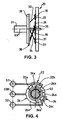
- the fixed portion 20 includes an electrically planar track conductive 21 for example made of metal such as copper. Runway 21 is shown in more detail in FIGS. 2 and 4. This track 21 is in fact consists of three sub-tracks 22, 24 and 26 which are interspersed alternately between each other so these three subtracks are arranged on the same circumference. In other words, and as this is described below in more detail, contrary to the prior art where the different tracks are concentric and therefore occupy a radial space important, the sub-tracks forming track 21 in accordance with this invention are of the same radial width and are arranged substantially on the same diameter.
- each sub-track has several segments conductors connected together by a conductive filament forming a terminal connection.
- the first sub-track 22 has two segments 22a and 22b of similar dimensions, that is, describing an angular sector equal and having an identical radial width. These segments 22a and 22b are interconnected by a first filament S1 outside the diameter of the segments 22a and 22b and forming a conductive connection terminal.
- the second sub-track 24 has two segments 24a and 24b, also of similar dimensions, interconnected by a second external filament S2 to the common diameter of the segments 24a and 24b and forming a second conductive connection terminal.
- the third sub-track 26 comprises four segments 26a, 26b, 26c and 26d of different circumferential dimensions interconnected by a third filament referenced COM outside the diameter of segments 26a to 26d, and forming a conductive connection terminal.
- An orifice 40 is made in the center of the conductive track 21 to lighten the structure or leave the place a device for rotating the movable part such as a tree rotary.
- the positioning of the segments of the different sub-tracks, on a complete turn and in the direction of clockwise is as follows: first segment 22a of the first sub-track 22, first segment 26a of the common sub-track 26, second segment 22b of the first sub-track 22, second segment 26b of the sub-track common track 26, first segment 24a of the second sub-track 24, third segment 26c of the common sub-track 26, second segment 24b of the second sub-track and fourth segment 26c of the common sub-track 26.
- the moving part 30 is controlled by the control member 31 manipulated by a user such as the driver or the front passenger of a vehicle, and includes in particular two rings 30a and 30b and three contactors 32, 34 and 36 made of electrically conductive metal such as copper.
- the contactors 32, 34 and 36 are each formed a flexible blade to the free end of which are bulging protuberances 33, 35 and 37 acting as contact.
- the three contactors 32, 34 and 36 are solidary of a ring 39 to form a wiper, and are arranged in such a way that said bulging protuberances are placed at 120 ° from each other on a common circumference, according to the exemplary embodiment.
- the protuberances 33, 35, and 37 are in front and in contact with the track conductor 21.
- Space saving also makes it possible to use the center of the encoder for example to place an additional button or pictograms.
- This encoder is inexpensive because it does not have welding or assembly binding and expensive and uses primary parts independent easy to achieve.
- a electrically conductive element 31 ' such as a copper pellet, is arranged under the central control knob 31 for controlling the mobile part 30.
- This electrically conductive element 31 ' is adapted to cooperate, by support substantially axially on said button 31 according to the arrow F, with a contactor electrical 22 'of the conductive track 21, for example under the form of a copper portion connected to the track 21.
- the device then performs both the rotary encoder function and validation of a transmitted data item, the validation taking place by pressing the button 31 of a precise position of the corresponding encoder, in example to a setting of the air conditioning unit to which it belongs. This can further reduce the size of the encoder on the board of control, and improves its ergonomics for the user.
- the relative rotary encoder 10 of the present invention comprises a track 21 copper and four electrical contactors 32, 34, 36 and 38.
- the track 21 has a first sub-track 22 provided with two segments identical 22a and 22b, a second sub-track 24 provided with two segments identical 24a and 24b, and a common sub-track 26 provided with twelve identical segments 26a to 26l.
- the positioning of the segments of the different sub-tracks, on a complete turn and in the direction counter clockwise is as follows: first and second segments 22a and 22b of the first sub-track 22, first to third segments 26a, 26b and 26c of the common sub-track 26, first and second segments 24a and 24b of the second sub-track 24 and finally, fourth to twelfth segments 26d, 26e, 26f, 26g, 26h, 26i, 26j, 26k and 26l of the sub-track ses 26.
- the contactors 32, 34, 36 and 38 are similar to those of first embodiment in that they consist of a flexible blade made of copper provided, at their free end, a sliding contact protrusion.
- the encoder has been carried out a rotation with respect to the initial position of a sixteenth of a turn in the anticlockwise along the arrow R.
- the contactor 32 is in electrical contact with the first sub-track 22 via the segment 22a, and the other contactors 34, 36 and 38 are in contact with the common sub-track 26, respectively via the segments 26c, 26th and 26th.
- An output binary signal "10" is output.
- the encoder has been carried out a rotation from the previous position of a sixteenth of a turn in the counter-clockwise along arrow R.
- Both contactors 32 and 34 are in contact with the first and second sub-tracks 22 and 24, respectively via the segments 22b and 24a, and the two other contactors 36 and 38 are in contact with the common sub-track 26, respectively through segments 26f and 26j.
- a signal output binary "11" is issued.
- the encoder has been carried out a rotation from the previous position of a sixteenth of a turn in the counter clockwise along arrow R.
- the contactor 34 is in electrical contact with the second sub-track 24 via of the segment 24b, and the other contactors 32, 36 and 38 are in contact with the common sub-track 26, respectively via the segments 26a, 26g and 26k.
- An output binary signal "01" is output.
- contactors 32, 34, 36 and 38 are arranged at 90 ° from each other on the same circumference, these four binary values are obtained over a quarter turn (or four sixteenth) and are again transmitted by the rotary encoder 10 according to the exactly same sequence if the rotation of said encoder is continued in the same meaning, the contactors simply performing a permutation circular with respect to the fixed segments.
- the number n of sub-tracks and contactors may be greater than three depending on the parameter to set of the ventilation device, heating and / or air conditioning.
- sub-tracks 1, 2 and 3 000, 001, 010, 011, 100, 101, 110 and 111. It can be for example eight intermediate positions of location of expelled air.
- the rotation of the encoder is preferably performed over 360 °, or on a number X turns, the number of possible values for the setting of a parameter of the airflow being equal to X times the number of segments. So with four binary values and three blades, it is possible to have 12 increments different in a small footprint.
- the blades extend radially and also axially with respect to the axis of rotation of the encoder, and thus has a certain axial elasticity allowing always keep in touch with the track.
Landscapes
- Physics & Mathematics (AREA)
- General Physics & Mathematics (AREA)
- Transmission And Conversion Of Sensor Element Output (AREA)
- Rotary Switch, Piano Key Switch, And Lever Switch (AREA)
- Switches With Compound Operations (AREA)
- Ultra Sonic Daignosis Equipment (AREA)
- Air-Conditioning For Vehicles (AREA)
- Power-Operated Mechanisms For Wings (AREA)
- Control Of Electric Motors In General (AREA)
Abstract
Description
- chaque contacteur présente une protubérance ayant une forme sensiblement bombée ;
- chaque contacteur comporte une lame flexible munie à son extrémité libre de ladite protubérance bombée ;
- la lame flexible de chaque contacteur s'étend au moins axialement par rapport à une couronne centrale de support, ou bien essentiellement radialement, dans le plan de ladite couronne, pour former un frotteur ;
- les contacteurs sont répartis de manière régulière,
- l'encodeur comporte trois contacteurs répartis sur une première circonférence commune et disposés sensiblement à 120° les uns des autres ;
- l'ordre des segments des sous-pistes sur une circonférence complète, et dans le sens des aiguilles d'une montre, est le suivant : premier segment d'une première sous-piste, premier segment d'une sous-piste commune, second segment de la première sous-piste, deuxième segment de la sous piste commune, premier segment d'une deuxième sous-piste, troisième segment de la sous-piste commune, second segment de la deuxième sous-piste et quatrième segment de la sous-piste commune ;
- lorsque tous les contacteurs sont en contact électrique avec la sous-piste commune, un signal binaire de sortie « 00 » est émis ;
- lorsqu'un contacteur est en contact électrique avec la deuxième sous-piste et que les autres contacteurs sont en contact avec la sous-piste commune, un signal binaire de sortie « 01 » est émis ;
- lorsqu'un contacteur est en contact électrique avec la première sous-piste et que les autres contacteurs sont en contact avec la sous-piste commune, un signal binaire de sortie « 10 » est émis ; et,
- lorsque deux contacteurs sont en contact avec les première et seconde sous-pistes et que le troisième contacteur est en contact avec la sous-piste commune, un signal binaire de sortie « 11 » est émis.
- l'encodeur comporte quatre contacteurs répartis sur une circonférence commune et disposés sensiblement à 90° les uns des autres ;
- une première sous-piste comporte deux segments, une seconde sous-piste comporte deux segments et une sous-piste commune comporte douze segments disposés en alternance avec les segments des première et seconde sous-pistes ;
- l'ordre des segments de sous-pistes, sur une circonférence complète et dans le sens inverse des aiguilles d'une montre, est le suivant : premier et second segments de la première sous-piste, premier à troisième segments de la sous-piste commune, premier et second segments de la deuxième sous-piste, quatrième à douzième segments de la sous-piste commune ;
- lorsque tous les contacteurs sont en contact électrique avec la sous-piste commune, un signal binaire de sortie « 00 » est émis ;
- lorsqu'un contacteur est en contact électrique avec la première sous-piste et que les autres contacteurs sont en contact avec la sous-piste commune, un signal binaire de sortie « 10 » est émis ;
- lorsque deux contacteurs sont en contact avec les première et seconde sous-pistes et que les deux autres contacteurs sont en contact avec la sous-piste commune, un signal binaire de sortie « 11 » est émis ; et
- lorsqu'un contacteur est en contact électrique avec la deuxième sous-piste et que les autres contacteurs sont en contact avec la sous-piste commune, un signal binaire de sortie « 01 » est émis.
- les secteurs angulaires décris par les segments des première et/ou deuxième sous-pistes sont identiques ;
- les secteurs angulaires décrits par les segments de toutes les sous pistes sous-pistes sont identiques ;
- les segments appartenant respectivement à une sous-piste sont reliés entre eux par au moins un filament commun, lesdits filaments étant disposés sur au moins une deuxième circonférence ;
- un orifice est aménagé au centre de la piste ;
- la partie mobile de l'encodeur comprend un bouton central de commande sous lequel se trouve un élément électriquement conducteur coopérant, par appui sensiblement axial sur le dit bouton, avec un contacteur électrique de la partie fixe, notamment pour valider une position prise par l'encodeur rotatif.
- la figure 1, une vue en perspective éclatée d'un encodeur relatif rotatif conforme à la présente invention,
- la figure 2, une vue de détail en perspective éclatée des parties fixe et mobile de l'encodeur qui sont en contact,
- la figure 3, une vue en coupe de l'encodeur,
- la figure 4, une vue de face d'une piste appartenant à la partie fixe de l'encodeur,
- les figures 5 à 8, des vues de face illustrant chacune une position prise par les parties fixe et mobile l'une par rapport à l'autre,
- la figure 9, une vie en perspective éclatée d'une variante de réalisation de la figure 2 illustrant un second mode de réalisation de l'invention, et
- les figures 10 à 13, des vues de face illustrant chacune une position différente prise par les parties fixe et mobile d'un troisième mode de réalisation de l'encodeur relatif comportant quatre contacteurs.
- lorsque les protubérances bombées 33, 35 et 37 des contacteurs 32, 34 et 36 sont en contact électrique avec la sous-piste commune 26 (voir figure 5), un signal binaire de sortie « 00 » est émis par l'encodeur,
- lorsque la protubérance bombée d'un contacteur par exemple la protubérance 37 du contacteur 36, est en contact électrique avec la deuxième sous-piste 24, par exemple avec le segment 24b, et que les protubérances bombées 33 et 35 des contacteurs 32 et 34 sont en contact avec la sous-piste commune 26 (voir figure 6), un signal binaire de sortie « 01 » est émis par l'encodeur,
- lorsque deux protubérances bombées de deux contacteurs, par exemple les protubérances 35 et 37 des contacteurs 34 et 36, sont en contact avec les première et seconde sous-pistes 22 et 24, par exemple avec les segments 22b et 24b, et que la protubérance 33 du contacteur 32 est en contact avec la sous-piste commune 26 (voir figure 7), un signal binaire de sortie « 11 » est émis par l'encodeur,
- lorsque la protubérance bombée d'un contacteur, par exemple la protubérance 35 du contacteur 34, est en contact électrique avec la première sous-piste 22, par exemple avec le segment 22b, et que les protubérances bombées 33 et 37 des contacteurs 32 et 36 sont en contact avec la sous-piste commune 26 (voir figure 8), un signal binaire de sortie « 10 » est émis par l'encodeur.
Claims (26)
- Encodeur relatif rotatif (10) comprenant une partie fixe (20) et une partie mobile (30) et au moins un contacteur (32 ; 34 ; 36 ; 38) positionné en regard d'une piste électriquement conductrice (21), le contacteur (32 ; 34 ; 36 ; 38) appartenant à la partie mobile (30) et la piste conductrice (21) appartenant à la partie fixe (20) ou inversement, caractérisé en ce qu'il comprend au moins un contacteur (32 ; 34 ; 36, 38) et au moins une sous-piste (22 ; 24 ; 26) comportant chacune au moins un segment (22a, 22b ; 24a, 24b ; 26a - 26l), les segments (22a, 22b ; 24a, 24b ; 26a - 26l) d'une même sous-piste (22 ; 24 ; 26) étant séparés les uns des autres par un segment d'une autre sous-piste, de sorte que la piste conductrice (21) présente une alternance de segments (22a, 22b ; 24a, 24b ; 26a - 26l) de sous-pistes (22, 24, 26) disposés sur une même circonférence.
- Encodeur selon la revendication 1, dans lequel chaque contacteur (32 ; 34 ; 36 ; 38) présent une protubérance (33 ; 35 ; 37) ayant une forme sensiblement bombée.
- Encodeur selon la revendication 2, dans lequel chaque contacteur (32 ; 34 ; 36 ; 38) comporte une lame flexible munie à son extrémité libre de ladite protubérance bombée (33 ; 35 ; 37).
- Encodeur selon la revendication 3, dans lequel chaque lame flexible de chaque contacteur (32 ; 34 ; 36 ; 38) s'étend radialement par rapport à une couronne (39) centrale de support pour former un frotteur.
- Encodeur selon la revendication la revendication 3 ou 4, dans lequel chaque lame flexible de chaque contacteur (32 ; 34 ; 36 ; 38) s'étend axialement par rapport à une couronne centrale (39) de support pour former un frotteur.
- Encodeur selon l'une quelconque des revendications précédentes, caractérisé en ce que les contacteurs (32, 34, 36, 38) sont répartis de manière régulière.
- Encodeur selon l'une quelconque des revendications précédentes, caractérisé en ce qu'il comporte trois contacteurs (32, 34, 36) répartis sur une circonférence commune et disposés sensiblement à 120° les uns des autres.
- Encodeur selon l'une quelconque des revendications précédentes, dans lequel une première sous-piste comporte (22) deux segments (22a, 22b), une seconde sous-piste (24) comporte deux segments (24a, 24b) et une sous-piste commune (26) comporte quatre segments (26a, 26b, 26c, 26d) disposés en alternance avec les segments (22a, 22b ; 24a, 24b) des première et seconde sous-pistes (22, 24).
- Encodeur selon la revendication 8, dans lequel l'ordre des segments (22a, 22b ; 24a, 24b ; 26a, 26b, 26c, 26d) de sous-pistes (22, 24, 26), sur une circonférence complète et dans le sens des aiguilles d'une montre, est le suivant : premier segment (22a) d'une première sous-piste (22), premier segment (26a) d'une sous-piste commune (26), second segment (22b) de la première sous-piste(22), deuxième segment (26b) de la sous piste commune (26), premier segment (24a) d'une deuxième sous-piste (24), troisième segment (26c) de la sous-piste commune (26), second segment (24b) de la deuxième sous-piste (24) et quatrième segment (26d) de la sous-piste commune (26).
- Encodeur selon la revendication 8 ou 9, dans lequel, lorsque tous les contacteurs (32, 34, 36) sont en contact électrique avec la sous-piste commune (26), un signal binaire de sortie « 00 » est émis.
- Encodeur selon la revendication 8 ou 9, dans lequel, lorsqu'un contacteur (32 ; 34 ; 36) est en contact électrique avec la deuxième sous-piste (2) et que les autres contacteurs (34, 36 ; 32, 36 ; 32, 34) sont en contact avec la sous-piste commune (26), un signal binaire de sortie « 01 » est émis.
- Encodeur selon la revendication 8 ou 9, dans lequel, lorsqu'un contacteur (32 ; 34 ; 36) est en contact électrique avec la première sous-piste (22) et que les autres contacteurs (34, 36 ; 32, 36 ; 32, 34) sont en contact avec la sous-piste commune (26), un signal binaire de sortie « 10 » est émis.
- Encodeur selon la revendication 8 ou 9, dans lequel, lorsque deux contacteurs (32, 34 ; 34, 36 ; 32, 36) sont en contact avec les première et seconde sous-pistes (22, 24) et que le troisième contacteur (32 ; 34 ; 36) est en contact avec la sous-piste commune (26), un signal binaire de sortie « 11 » est émis.
- Encodeur selon l'une quelconque des revendications 1 à 6, caractérisé en ce qu'il comporte quatre contacteurs (32, 34, 36, 38) répartis sur une circonférence commune et disposés sensiblement à 90° les uns des autres.
- Encodeur selon la revendication 14, dans lequel une première sous-piste (22) comporte deux segments (22a, 22b), une seconde sous-piste (24) comporte deux segments (24a, 24b) et une sous-piste commune (26) comporte douze segments (26a - 26l) disposés en alternance avec les segments (22a, 22b ; 24a, 24b) des première et seconde sous-pistes (22, 24).
- Encodeur selon la revendication 15, dans lequel l'ordre des segments (22a, 22b ; 24a, 24b ; 26a - 26l) de sous-pistes (22, 24, 26), sur une circonférence complète et dans le sens inverse des aiguilles d'une montre, est le suivant : premier et second segments (22a, 22b) de la première sous-piste (22), premier à troisième segments (26a, 26b, 26c) de la sous-piste commune (26), premier et second segments (24a, 24b) de la deuxième sous-piste (24), quatrième à douzième segments (26d, 26e, 26f, 26g, 26h, 26i, 26j, 26k, 26l) de la sous-piste commune (26).
- Encodeur selon la revendication 15 ou 16, dans lequel, lorsque tous les contacteurs (32, 34, 36, 38) sont en contact électrique avec la sous-piste commune (26), un signal binaire de sortie « 00 » est émis.
- Encodeur selon la revendication 15 ou 16, dans lequel, lorsqu'un contacteur (32 ; 34 ; 36 ; 38) est en contact électrique avec la première sous-piste (22) et que les autres contacteurs (34, 36, 38 ; 32, 36, 38 ; 32, 34, 38 ; 32, 34, 36) sont en contact avec la sous-piste commune (26), un signal binaire de sortie « 10 » est émis.
- Encodeur selon la revendication 15 ou 16, dans lequel, lorsque deux contacteurs (32, 34 ; 34, 36 ; 36, 38 ; 38, 32) sont en contact avec les première et seconde sous-pistes (22, 24) et que les deux autres contacteurs (36, 38 ; 32, 38 ; 32, 34 ; 34, 36) sont en contact avec la sous-piste commune (26), un signal binaire de sortie « 11 » est émis.
- Encodeur selon la revendication 15 ou 16, dans lequel, lorsqu'un contacteur (32 ; 34 ; 36 ; 38) est en contact électrique avec la deuxième sous-piste (24) et que les autres contacteurs (34, 36, 38 ; 32, 36, 38 ; 32, 34 ; 38 ; 32, 34, 36) sont en contact avec la sous-piste commune (26), un signal binaire de sortie « 01 » est émis.
- Encodeur selon l'une quelconque des revendications précédentes, dans lequel les secteurs angulaires décrits par les segments (22a, 22b ; 24a, 24b) des première et/ou deuxième sous-pistes (22, 24) sont identiques.
- Encodeur selon l'une quelconque des revendications 14 à 21, dans lequel les secteurs angulaires (22a, 22b ; 24a, 24b ; 26a - 26l) décrits par les segments de toutes les sous-pistes (22, 24, 26) sont identiques.
- Encodeur selon l'une quelconque des revendications précédentes, dans lequel tous les segments (22a, 22b ; 24a, 24b ; 26a - 26l) appartenant respectivement à une sous-piste (22 ; 24 ; 26) sont reliés entre eux par au moins un filament commun (S1 ; S2, COM), lesdits filaments étant disposés sur au moins une deuxième circonférence.
- Encodeur selon l'une quelconque des revendications précédentes, caractérisé en ce qu'un orifice (40) est aménagé au centre de la piste (21).
- Encodeur selon l'une quelconque des revendications précédentes, caractérisé en ce que la partie mobile (30) comprend un bouton central (31) de commande sous lequel se trouve un élément électriquement conducteur (31') coopérant, par appui sensiblement axial sur le dit bouton (31), avec un contacteur électrique (22') de la partie fixe (20), notamment pour valider une position prise par l'encodeur rotatif.
- Tableau de commande (12), par exemple pour appareil de chauffage, de ventilation et/ou de climatisation de véhicule automobile, muni d'un encodeur relatif (10) selon l'une quelconque des revendications précédentes.
Applications Claiming Priority (2)
| Application Number | Priority Date | Filing Date | Title |
|---|---|---|---|
| FR0400567A FR2865274B1 (fr) | 2004-01-21 | 2004-01-21 | Encodeur relatif rotatif, et tableau de commande de vehicule automobile muni d'un tel encodeur. |
| FR0400567 | 2004-01-21 |
Publications (2)
| Publication Number | Publication Date |
|---|---|
| EP1557645A1 true EP1557645A1 (fr) | 2005-07-27 |
| EP1557645B1 EP1557645B1 (fr) | 2009-02-04 |
Family
ID=34630661
Family Applications (1)
| Application Number | Title | Priority Date | Filing Date |
|---|---|---|---|
| EP05001087A Expired - Lifetime EP1557645B1 (fr) | 2004-01-21 | 2005-01-20 | Encodeur relatif rotatif et tableau de commande de véhicule automobile muni d'un tel encodeur |
Country Status (5)
| Country | Link |
|---|---|
| EP (1) | EP1557645B1 (fr) |
| AT (1) | ATE422234T1 (fr) |
| DE (1) | DE602005012610D1 (fr) |
| ES (1) | ES2321949T3 (fr) |
| FR (1) | FR2865274B1 (fr) |
Cited By (1)
| Publication number | Priority date | Publication date | Assignee | Title |
|---|---|---|---|---|
| CN115493628A (zh) * | 2022-11-16 | 2022-12-20 | 惠州市正牌科电有限公司 | 一种码盘、格雷码编码器及其编码方法 |
Citations (4)
| Publication number | Priority date | Publication date | Assignee | Title |
|---|---|---|---|---|
| US3398245A (en) * | 1966-09-13 | 1968-08-20 | United Carr Inc | Printed circuit switch |
| US4345240A (en) * | 1979-02-08 | 1982-08-17 | Aisin Seiki Kabushiki Kaisha | Throttle opening sensor |
| DE3136045A1 (de) * | 1981-09-11 | 1983-03-31 | Fritz Hartmann Gerätebau GmbH, 8581 Eckersdorf | Codierdrehschalter |
| WO1996019872A1 (fr) * | 1994-12-20 | 1996-06-27 | Bourns Inc. | Dispositif numerique d'entree et de commande |
-
2004
- 2004-01-21 FR FR0400567A patent/FR2865274B1/fr not_active Expired - Lifetime
-
2005
- 2005-01-20 AT AT05001087T patent/ATE422234T1/de not_active IP Right Cessation
- 2005-01-20 ES ES05001087T patent/ES2321949T3/es not_active Expired - Lifetime
- 2005-01-20 DE DE602005012610T patent/DE602005012610D1/de not_active Expired - Lifetime
- 2005-01-20 EP EP05001087A patent/EP1557645B1/fr not_active Expired - Lifetime
Patent Citations (4)
| Publication number | Priority date | Publication date | Assignee | Title |
|---|---|---|---|---|
| US3398245A (en) * | 1966-09-13 | 1968-08-20 | United Carr Inc | Printed circuit switch |
| US4345240A (en) * | 1979-02-08 | 1982-08-17 | Aisin Seiki Kabushiki Kaisha | Throttle opening sensor |
| DE3136045A1 (de) * | 1981-09-11 | 1983-03-31 | Fritz Hartmann Gerätebau GmbH, 8581 Eckersdorf | Codierdrehschalter |
| WO1996019872A1 (fr) * | 1994-12-20 | 1996-06-27 | Bourns Inc. | Dispositif numerique d'entree et de commande |
Cited By (2)
| Publication number | Priority date | Publication date | Assignee | Title |
|---|---|---|---|---|
| CN115493628A (zh) * | 2022-11-16 | 2022-12-20 | 惠州市正牌科电有限公司 | 一种码盘、格雷码编码器及其编码方法 |
| CN115493628B (zh) * | 2022-11-16 | 2023-04-07 | 惠州市正牌科电有限公司 | 一种码盘、格雷码编码器及其编码方法 |
Also Published As
| Publication number | Publication date |
|---|---|
| FR2865274A1 (fr) | 2005-07-22 |
| DE602005012610D1 (de) | 2009-03-19 |
| ES2321949T3 (es) | 2009-06-15 |
| FR2865274B1 (fr) | 2006-04-28 |
| EP1557645B1 (fr) | 2009-02-04 |
| ATE422234T1 (de) | 2009-02-15 |
Similar Documents
| Publication | Publication Date | Title |
|---|---|---|
| WO2015033033A1 (fr) | Interface de commande à retour haptique | |
| EP1881514A1 (fr) | Dispositif de commande à détection de position | |
| FR2950166A1 (fr) | Dispositif de commande rotatif a retour haptique | |
| EP3013649B1 (fr) | Contacteur tournant pour une colonne de direction de vehicule automobile | |
| WO2007147791A1 (fr) | Dispositif de commande electrique | |
| WO2012101122A1 (fr) | Dispositif d'actionnement d'un equipement pilotable automatiquement ou manuellement avec detection de la reprise du pilotage manuel | |
| FR3056474A1 (fr) | Interface pour vehicule automobile | |
| FR3079179A1 (fr) | Interface pour vehicule automobile | |
| EP1557645B1 (fr) | Encodeur relatif rotatif et tableau de commande de véhicule automobile muni d'un tel encodeur | |
| WO2012085363A1 (fr) | Bouton et dispositif de commande multifonction | |
| FR2842766A1 (fr) | Dispositif de commande de fonctions muni d'un selecteur et planche de bord de vehicule automobile equipee d'un tel dispositif | |
| EP0823347B1 (fr) | Dispositif de commande d'appareils par exemple dans un véhicule automobile | |
| WO2007010109A1 (fr) | Unite d'indexage et un dispositif de commande comprenant une telle unite d'indexage | |
| EP4279872B1 (fr) | Codeur magnétique incrémental | |
| FR3102433A1 (fr) | Interface et organe de commande de véhicule automobile | |
| FR2878369A1 (fr) | Bouton de commande a encodeur mecanique | |
| EP1300861B1 (fr) | Commande monobouton | |
| FR2706690A1 (fr) | Contacteur électrique tournant. | |
| FR2783483A1 (fr) | Systeme a capteur d'angle, notamment pour colonne de direction de vehicule automobile | |
| EP4280463B1 (fr) | Bouton poussoir magnétique | |
| FR2998414A1 (fr) | "dispositif perfectionne de commande a tambour et a voies de commutation multiples" | |
| EP2151842A1 (fr) | Commutateur comprenant un système d'indexation ayant une came en V et un index à embout hémisphérique | |
| EP1607268B1 (fr) | Système d'indexage mécanique, notamment pour commutateur électrique | |
| WO2025099050A1 (fr) | Périphérique haptique motorisé | |
| EP1798524B1 (fr) | Capteur de position angulaire |
Legal Events
| Date | Code | Title | Description |
|---|---|---|---|
| PUAI | Public reference made under article 153(3) epc to a published international application that has entered the european phase |
Free format text: ORIGINAL CODE: 0009012 |
|
| AK | Designated contracting states |
Kind code of ref document: A1 Designated state(s): AT BE BG CH CY CZ DE DK EE ES FI FR GB GR HU IE IS IT LI LT LU MC NL PL PT RO SE SI SK TR |
|
| AX | Request for extension of the european patent |
Extension state: AL BA HR LV MK YU |
|
| 17P | Request for examination filed |
Effective date: 20051205 |
|
| AKX | Designation fees paid |
Designated state(s): AT BE BG CH CY CZ DE DK EE ES FI FR GB GR HU IE IS IT LI LT LU MC NL PL PT RO SE SI SK TR |
|
| 17Q | First examination report despatched |
Effective date: 20060804 |
|
| 17Q | First examination report despatched |
Effective date: 20060804 |
|
| GRAP | Despatch of communication of intention to grant a patent |
Free format text: ORIGINAL CODE: EPIDOSNIGR1 |
|
| GRAS | Grant fee paid |
Free format text: ORIGINAL CODE: EPIDOSNIGR3 |
|
| GRAA | (expected) grant |
Free format text: ORIGINAL CODE: 0009210 |
|
| AK | Designated contracting states |
Kind code of ref document: B1 Designated state(s): AT BE BG CH CY CZ DE DK EE ES FI FR GB GR HU IE IS IT LI LT LU MC NL PL PT RO SE SI SK TR |
|
| REG | Reference to a national code |
Ref country code: GB Ref legal event code: FG4D Free format text: NOT ENGLISH |
|
| REG | Reference to a national code |
Ref country code: CH Ref legal event code: EP |
|
| REG | Reference to a national code |
Ref country code: IE Ref legal event code: FG4D Free format text: LANGUAGE OF EP DOCUMENT: FRENCH |
|
| REF | Corresponds to: |
Ref document number: 602005012610 Country of ref document: DE Date of ref document: 20090319 Kind code of ref document: P |
|
| REG | Reference to a national code |
Ref country code: ES Ref legal event code: FG2A Ref document number: 2321949 Country of ref document: ES Kind code of ref document: T3 |
|
| NLV1 | Nl: lapsed or annulled due to failure to fulfill the requirements of art. 29p and 29m of the patents act | ||
| PG25 | Lapsed in a contracting state [announced via postgrant information from national office to epo] |
Ref country code: LT Free format text: LAPSE BECAUSE OF FAILURE TO SUBMIT A TRANSLATION OF THE DESCRIPTION OR TO PAY THE FEE WITHIN THE PRESCRIBED TIME-LIMIT Effective date: 20090204 Ref country code: FI Free format text: LAPSE BECAUSE OF FAILURE TO SUBMIT A TRANSLATION OF THE DESCRIPTION OR TO PAY THE FEE WITHIN THE PRESCRIBED TIME-LIMIT Effective date: 20090204 Ref country code: NL Free format text: LAPSE BECAUSE OF FAILURE TO SUBMIT A TRANSLATION OF THE DESCRIPTION OR TO PAY THE FEE WITHIN THE PRESCRIBED TIME-LIMIT Effective date: 20090204 Ref country code: SI Free format text: LAPSE BECAUSE OF FAILURE TO SUBMIT A TRANSLATION OF THE DESCRIPTION OR TO PAY THE FEE WITHIN THE PRESCRIBED TIME-LIMIT Effective date: 20090204 |
|
| PG25 | Lapsed in a contracting state [announced via postgrant information from national office to epo] |
Ref country code: SE Free format text: LAPSE BECAUSE OF FAILURE TO SUBMIT A TRANSLATION OF THE DESCRIPTION OR TO PAY THE FEE WITHIN THE PRESCRIBED TIME-LIMIT Effective date: 20090504 Ref country code: AT Free format text: LAPSE BECAUSE OF FAILURE TO SUBMIT A TRANSLATION OF THE DESCRIPTION OR TO PAY THE FEE WITHIN THE PRESCRIBED TIME-LIMIT Effective date: 20090204 Ref country code: IS Free format text: LAPSE BECAUSE OF FAILURE TO SUBMIT A TRANSLATION OF THE DESCRIPTION OR TO PAY THE FEE WITHIN THE PRESCRIBED TIME-LIMIT Effective date: 20090604 Ref country code: PL Free format text: LAPSE BECAUSE OF FAILURE TO SUBMIT A TRANSLATION OF THE DESCRIPTION OR TO PAY THE FEE WITHIN THE PRESCRIBED TIME-LIMIT Effective date: 20090204 |
|
| REG | Reference to a national code |
Ref country code: IE Ref legal event code: FD4D |
|
| PG25 | Lapsed in a contracting state [announced via postgrant information from national office to epo] |
Ref country code: IE Free format text: LAPSE BECAUSE OF FAILURE TO SUBMIT A TRANSLATION OF THE DESCRIPTION OR TO PAY THE FEE WITHIN THE PRESCRIBED TIME-LIMIT Effective date: 20090204 Ref country code: EE Free format text: LAPSE BECAUSE OF FAILURE TO SUBMIT A TRANSLATION OF THE DESCRIPTION OR TO PAY THE FEE WITHIN THE PRESCRIBED TIME-LIMIT Effective date: 20090204 Ref country code: DK Free format text: LAPSE BECAUSE OF FAILURE TO SUBMIT A TRANSLATION OF THE DESCRIPTION OR TO PAY THE FEE WITHIN THE PRESCRIBED TIME-LIMIT Effective date: 20090204 Ref country code: PT Free format text: LAPSE BECAUSE OF FAILURE TO SUBMIT A TRANSLATION OF THE DESCRIPTION OR TO PAY THE FEE WITHIN THE PRESCRIBED TIME-LIMIT Effective date: 20090706 |
|
| PG25 | Lapsed in a contracting state [announced via postgrant information from national office to epo] |
Ref country code: RO Free format text: LAPSE BECAUSE OF FAILURE TO SUBMIT A TRANSLATION OF THE DESCRIPTION OR TO PAY THE FEE WITHIN THE PRESCRIBED TIME-LIMIT Effective date: 20090204 |
|
| PLBE | No opposition filed within time limit |
Free format text: ORIGINAL CODE: 0009261 |
|
| STAA | Information on the status of an ep patent application or granted ep patent |
Free format text: STATUS: NO OPPOSITION FILED WITHIN TIME LIMIT |
|
| 26N | No opposition filed |
Effective date: 20091105 |
|
| PG25 | Lapsed in a contracting state [announced via postgrant information from national office to epo] |
Ref country code: BG Free format text: LAPSE BECAUSE OF FAILURE TO SUBMIT A TRANSLATION OF THE DESCRIPTION OR TO PAY THE FEE WITHIN THE PRESCRIBED TIME-LIMIT Effective date: 20090504 |
|
| BERE | Be: lapsed |
Owner name: VALEO SYSTEMES THERMIQUES Effective date: 20100131 |
|
| PG25 | Lapsed in a contracting state [announced via postgrant information from national office to epo] |
Ref country code: MC Free format text: LAPSE BECAUSE OF NON-PAYMENT OF DUE FEES Effective date: 20100131 |
|
| REG | Reference to a national code |
Ref country code: CH Ref legal event code: PL |
|
| PG25 | Lapsed in a contracting state [announced via postgrant information from national office to epo] |
Ref country code: CH Free format text: LAPSE BECAUSE OF NON-PAYMENT OF DUE FEES Effective date: 20100131 Ref country code: LI Free format text: LAPSE BECAUSE OF NON-PAYMENT OF DUE FEES Effective date: 20100131 Ref country code: GR Free format text: LAPSE BECAUSE OF FAILURE TO SUBMIT A TRANSLATION OF THE DESCRIPTION OR TO PAY THE FEE WITHIN THE PRESCRIBED TIME-LIMIT Effective date: 20090505 |
|
| PG25 | Lapsed in a contracting state [announced via postgrant information from national office to epo] |
Ref country code: BE Free format text: LAPSE BECAUSE OF NON-PAYMENT OF DUE FEES Effective date: 20100131 |
|
| PG25 | Lapsed in a contracting state [announced via postgrant information from national office to epo] |
Ref country code: CY Free format text: LAPSE BECAUSE OF FAILURE TO SUBMIT A TRANSLATION OF THE DESCRIPTION OR TO PAY THE FEE WITHIN THE PRESCRIBED TIME-LIMIT Effective date: 20090204 |
|
| PG25 | Lapsed in a contracting state [announced via postgrant information from national office to epo] |
Ref country code: LU Free format text: LAPSE BECAUSE OF NON-PAYMENT OF DUE FEES Effective date: 20100120 Ref country code: HU Free format text: LAPSE BECAUSE OF FAILURE TO SUBMIT A TRANSLATION OF THE DESCRIPTION OR TO PAY THE FEE WITHIN THE PRESCRIBED TIME-LIMIT Effective date: 20090805 |
|
| PG25 | Lapsed in a contracting state [announced via postgrant information from national office to epo] |
Ref country code: TR Free format text: LAPSE BECAUSE OF FAILURE TO SUBMIT A TRANSLATION OF THE DESCRIPTION OR TO PAY THE FEE WITHIN THE PRESCRIBED TIME-LIMIT Effective date: 20090204 |
|
| REG | Reference to a national code |
Ref country code: FR Ref legal event code: PLFP Year of fee payment: 12 |
|
| PGFP | Annual fee paid to national office [announced via postgrant information from national office to epo] |
Ref country code: CZ Payment date: 20161219 Year of fee payment: 13 Ref country code: SK Payment date: 20161216 Year of fee payment: 13 |
|
| REG | Reference to a national code |
Ref country code: FR Ref legal event code: PLFP Year of fee payment: 13 |
|
| PGFP | Annual fee paid to national office [announced via postgrant information from national office to epo] |
Ref country code: FR Payment date: 20170131 Year of fee payment: 13 |
|
| PGFP | Annual fee paid to national office [announced via postgrant information from national office to epo] |
Ref country code: GB Payment date: 20170120 Year of fee payment: 13 |
|
| PGFP | Annual fee paid to national office [announced via postgrant information from national office to epo] |
Ref country code: ES Payment date: 20170131 Year of fee payment: 13 Ref country code: IT Payment date: 20170113 Year of fee payment: 13 |
|
| GBPC | Gb: european patent ceased through non-payment of renewal fee |
Effective date: 20180120 |
|
| REG | Reference to a national code |
Ref country code: SK Ref legal event code: MM4A Ref document number: E 5691 Country of ref document: SK Effective date: 20180120 |
|
| PG25 | Lapsed in a contracting state [announced via postgrant information from national office to epo] |
Ref country code: FR Free format text: LAPSE BECAUSE OF NON-PAYMENT OF DUE FEES Effective date: 20180131 |
|
| REG | Reference to a national code |
Ref country code: FR Ref legal event code: ST Effective date: 20180928 |
|
| PG25 | Lapsed in a contracting state [announced via postgrant information from national office to epo] |
Ref country code: SK Free format text: LAPSE BECAUSE OF NON-PAYMENT OF DUE FEES Effective date: 20180120 Ref country code: CZ Free format text: LAPSE BECAUSE OF NON-PAYMENT OF DUE FEES Effective date: 20180120 Ref country code: GB Free format text: LAPSE BECAUSE OF NON-PAYMENT OF DUE FEES Effective date: 20180120 |
|
| PG25 | Lapsed in a contracting state [announced via postgrant information from national office to epo] |
Ref country code: IT Free format text: LAPSE BECAUSE OF NON-PAYMENT OF DUE FEES Effective date: 20180120 |
|
| REG | Reference to a national code |
Ref country code: ES Ref legal event code: FD2A Effective date: 20190731 |
|
| PG25 | Lapsed in a contracting state [announced via postgrant information from national office to epo] |
Ref country code: ES Free format text: LAPSE BECAUSE OF NON-PAYMENT OF DUE FEES Effective date: 20180121 |
|
| PGFP | Annual fee paid to national office [announced via postgrant information from national office to epo] |
Ref country code: DE Payment date: 20230112 Year of fee payment: 19 |
|
| P01 | Opt-out of the competence of the unified patent court (upc) registered |
Effective date: 20230528 |
|
| REG | Reference to a national code |
Ref country code: DE Ref legal event code: R119 Ref document number: 602005012610 Country of ref document: DE |
|
| PG25 | Lapsed in a contracting state [announced via postgrant information from national office to epo] |
Ref country code: DE Free format text: LAPSE BECAUSE OF NON-PAYMENT OF DUE FEES Effective date: 20240801 |
|
| PG25 | Lapsed in a contracting state [announced via postgrant information from national office to epo] |
Ref country code: DE Free format text: LAPSE BECAUSE OF NON-PAYMENT OF DUE FEES Effective date: 20240801 |